

Page 1
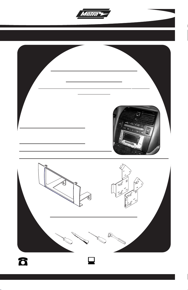
INSTALLATION INSTRUCTIONS FOR PART 95-8153
APPLICATIONS
LEXUS LS SERIES
1995-2000
NOT FOR USE IN VEHICLES WITH FACTORY
NAVIGATION
95-8153
KIT FEATURES
• Double DIN Radio Provision
• Stacked ISO Mount Units Provision
KIT COMPONENTS
A) Double DIN Radio Housing B) Double DIN Brackets
A
TOOLS REQUIRED:
Small Flat Blade Screwdriver/ Panel Removal Tool
• Phillips Screwdriver • Socket Set
1-800-221-0932
© COPYRIGHT 2008 METRA ELECTRONICS CORPORA
B
www.metr
aonline.com
TION
Page 2

95-8153
TABLE OF CONTENTS
Dash Disassembly
-
Lexus LS Series 1995-2000 . . . . . . . . . . . . . . . . . . . . . . . . . . . .
1
Kit Assembly
- Double DIN Radio Provision . . . . . . . . . . . . . . . . . . . . . . . . . . . . . . . . 2
- Stacked ISO Mount Units Provision . . . . . . . . . . . . . . . . . . . . . . . . . . 2
Assembly . . . . . . . . . . . . . . . . . . . . . . . . . . . . . . . . . . . . . . . . . . . 3
Final
*Note:
Refer also to the instructions included with the aftermarket radio.
Page 3

95-8153 DASH DISASSEMBLY
1
2
3
4
5
6
SCAN P.SCAN
TUNE
SEEK
TRACK
BASS
MID
TREBLE BALANCE FADER
AM
FM1/2
TAPE
CD
TEMP
TEMP
FRONT
REAR
A/C
OFF
AUTO
MODE
DUAL
PASSENGER
1
2
3
4
5
6
SCAN P.SCAN
TUNE
SEEK
TRACK
B
ASS
MID
TREBLE BALANCE FADER
A
M
F
M1/2
TAPE
C
D
TEMP
TEMP
F
RONT
REAR
A/C
OFF
A
UTO
MODE
DUAL
PASSENGER
ONE SCREW
ON EACH
SIDE
LEXUS LS SERIES 1995-2000
Disconnect the negative battery ter-
1
minal to prevent an accidental short
circuit.
Starting at rear of panel surrounding
2
the shifter carefully pry up and out to
remove entire panel including ashtray.
(
Figure A)
Using a panel removal tool or small
3
flat blade screwdriver gently pry out
on the top of the A/C vent assembly
(including clock) and remove.
(Figure B)
Remove (4) screws securing the fac-
4
tory radio/climate control assembly.
Unplug and remove the assembly.
(Figure C)
Remove (2) screws securing factory
5
climate control to the assembly.
Remove the climate control from the
assembly and retain it for re-use during kit assembly. (
Figure D)
A
B
Continue to kit assembly.
D
C
1
Page 4

95-8153 KIT ASSEMBLY
LEXUS LS SERIES 1995-2000
DOUBLE DIN RADIO
STACKED ISO MOUNT UNITS PROVISON
Note: Refer also to the instructions included with the aftermarket radio.
Snap the Double DIN Brackets onto
1
the Double DIN Radio Housing.
(Figure A)
Slide the factory climate controls into
2
the Bracket/Radio Housing assembly
aligning the top of the assembly with
alignment pins in the bottom of the
climate controls and secure using the
factory hardware.
Slide the Double DIN or stacked ISO
3
mount units into the bracket/radio
housing assembly and secure the
Double DIN or stacked ISO mount
units to the assembly using the
screws supplied with the Double DIN
or stacked ISO mount units.
(Figure B)
(Figure C)
A
B
Continue to final assembly.
C
2
Page 5

95-8153 FINAL ASSEMBLY
FINAL ASSEMBLY
A
(A) Strip wire ends back 1/2"
B
B) Twist ends together
C) Solder
C
D
Locate the factory wiring harness in the dash. Metra recommends using the
1
proper mating adapter and making connections as shown. (Isolate and individually tape off the ends of any unused wires to prevent electrical short circuit.)
Re-connect the negative battery terminal and test the unit for proper operation.
2
Reassemble radio and dash assemblies in reverse order of disassembly.
3
D) Tape
FINAL WIRING CONNECTIONS
Make wiring connections using the EIA color code chart shown below and the instructions included with the
head unit. Metra recommends making connections as shown below; Strip, Splice, Solder, Tape. Isolate and
individually tape off ends of any unused wires to prevent electrical short circuit.
METRA / EIA WIRING CODE
12V Ignition / Acc . . . . . . . . . . Red
12V Batt / Memory. . . . . . . . . Yellow
Ground. . . . . . . . . . . . . . . . . . Black*
Power Antenna. . . . . . . . . . . . Blue
Amp Turn-On . . . . . . . . . . . . . Blue / White
Amp Ground. . . . . . . . . . . . . . Black / White
. . . . . . . . . . . . . .
tion
Illumina
Dimmer . . . . . . . . . . . . . . . . . Orange / White
Orange
Right Front (+) . . . . . . . . . . . . Gray
Right Front (-). . . . . . . . . . . . . Gray/ Black
Left Front (+) . . . . . . . . . . . . . White
Left Front (-). . . . . . . . . . . . . . White / Black
Right Rear (+) . . . . . . . . . . . . Violet
Right Rear (-) . . . . . . . . . . . . . Violet / Black
Left Rear (+)
Left Rear (-) . . . . . . . . . . . . . . Green / Black
. . . . . . . . . . . . .
Green
*NOTE: When a Black wire is not present, ground radio to vehicle chassis.
All colors may not be present on all leads due to manufacturer’s specifications.
3
Page 6

95-8153
NOTES
4
Page 7

95-8153
NOTES
5
Page 8

95-8153 INSTRUCTIONS
1-800-221-0932
REV. 04/29/08 © COPYRIGHT 2008 METRA ELECTRONICS CORPORATION INST95-8153
www.metraonline.com
 Loading...