

Page 1
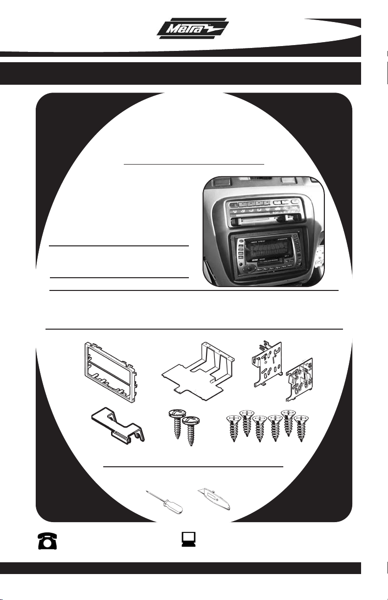
INSTALLATION INSTRUCTIONS FOR PART 95-7801
APPLICATIONS
See Application List Inside
95-7801
KIT FEATURES
• Double DIN Radio Provision
• Stacked ISO Units Provision
KIT COMPONENTS
• A) Radio Housing • B) Rear Support Tray • C) ISO Brackets
• D) Mounting Bracket (Acura legend) • E) (2) #8 x 1/2” Phillips Pan Head Screws
• F) (6) #6 x 1/4” Phillips Flat Head Screws
A
D
1-800-221-0932
© COPYRIGHT 2001-2008 METRA ELECTRONICS CORPORA
B
E
TOOLS REQUIRED:
• Phillips Screwdriver • Cutting Tool
F
www.metr
C
aonline.com
TION
Page 2

95-7801
TABLE OF CONTENTS
Dash Disassembly / Kit Preparation
- ACURA
- CL 1997-99 . . . . . . . . . .
- Integra 1990-93 . . . . . . .
- Integra 1994-01 . . . . . . . . . . . . . . . . .
-
Legend 1990-96 ..............................
- TL 1996-98 . . . . . . . . . .
- Vigor 1992-94 . . . . . . . . .
- HONDA
- Accord 1990-93 . . . . . . . . . . . . . . . . .
- Accord 1994-97 . . . . . . . . . . . . . . . . .
- Accord 1998-02 . . . . . . . . . . . . . . . . .
- Civic 1999-00 . . . . . . . . . . . . . . . . . . .
- CRV 1997-01... . . . . . . . . . . . . . . . .
- CRV 2002-06 . . . . . . . . . . . . . . . . . . . .
- Odyssey 1995-99 . . . . . . . . . . . . . . . .
- Odyssey 1999-04 . . . . . . . . . . . . . . . .
- Prelude 1992-96 . . . . . . . . . . . . . . . . .
- Prelude 1997-01 . . . . . . . . . . . . . . . . .
- ISUZU
- Oasis 1996-99 . . . . . . . . . . . . . . . . . .
. .........................
.........................
................
..........................
.........................
................
................
. . . .............
................
................
................
. . . . ............
. . ..............
................
................
................
. . . . ..1
. . . . . . 1
. . . . . . 2
. . . . . . 2
. . . . . . 3
. . . . . . 3
. . . . . . 4
. . . . . . 4
. . . . . .5
. . . . . . 5
. . . . . . 6
. . . . . . 6
. . . . . . 7
. . . . ..7
. . . . . . 8
. . . . . . 8
. . . . . . 7
Kit Assembly
- Kit Assembly Preparation . . . . . . . . . . . . . . . . . . . . . . . . . . . . . . . . . . .9
- DIN Radio with Pocket Provision . . . . . . . . . . . . . . . . . . . . . . . . . . . . 10
- ISO Mount Radio with Pocket Provision . . . . . . . . . . . . . . . . . . . . . . . 10
Final Assembly . . . . . . . . . . . . . . . . . . . . . . . . . . . . . . . . . . . . . . . . . .11
*Note:
Refer also to the instructions included with the aftermarket radio.
Page 3
95-7801 DASH DISASSEMBLY
"A"
"A"
"H"
"H"
2
"C"
"C"
"H"
"H"
Fig. A
Fig. B
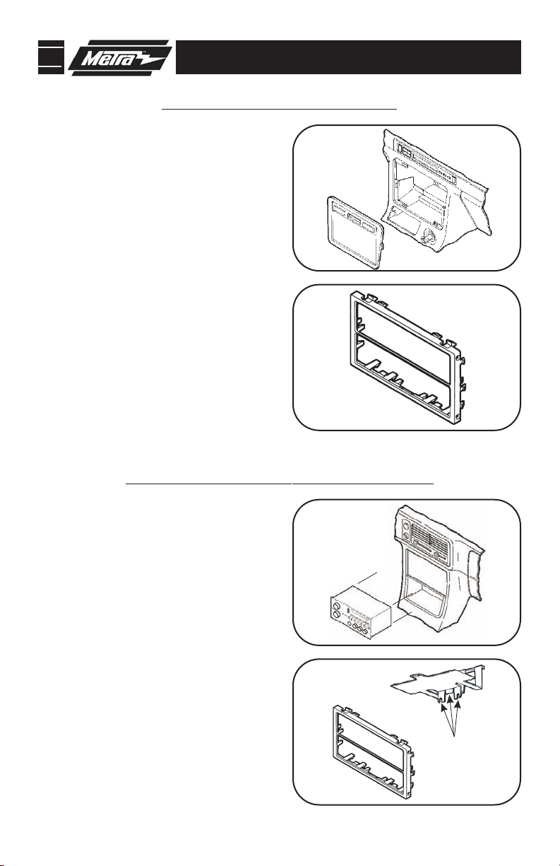
ACURA CL 1997-1999
1
Disconnect the negative battery terminal to prevent an accidental short circuit.
Unclip the radio trim bezel and disconnect the
2
clock and climate control wiring. Remove (2)
8mm hex-head screws securing the factory
head unit and disconnect the wiring. (Fig. A)
Cut and remove all mounting clips on the Radio
3
Housing EXCEPT clips "A" and "H". (Fig. B)
Skip to step #3b on Page 10.
CURA INTEGRA 1990-1993
A
1
Disconnect the negative battery terminal to prevent an accidental short circuit.
Remove (3) screws from each side of the center
2
console and remove the console. Remove (2)
screws securing the factory head unit to the
sub-dash support bracket. Slide the head
unit/pocket assembly out and disconnect the
wiring. (Fig. A)
3
Cut and remove the mounting tabs from the bottom of the Rear Support Tray (Fig. A). Cut and
remove all mounting clips on the
Housing EXCEPT clips "C" and "H" (Fig
Skip to step #3b on Page 10.
Radio
. B).
A
B
A
B
1
Page 4
95-7801 DASH DISASSEMBLY
2
"C"
"C"
Fig. A
Fig. B
"H"
"H"
"E"
"E"
"J"
"J"
Fig. A
Fig. B
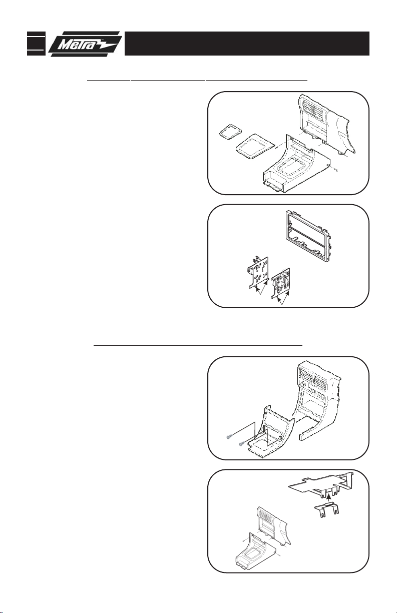
ACURA INTEGRA 1994-2001
1
Disconnect the negative battery terminal to prevent an accidental short circuit.
Remove the cover cap located under the emer-
2
gency brake and remove (2) screws exposed.
Remove (2) screws from the rear corners of the
lower dash trim bezel and remove. Remove the
ashtray and (2) screws exposed. Unsnap the
ashtray housing and disconnect the cigarette
lighter harness. Remove the gear shifter knob
and unsnap the shifter trim. Remove (2) screws
below the radio opening and remove the upper
dash trim bezel. Remove (2) 8mm screws securing the factory head unit and disconnect the
wiring. (Fig. A)
3
Cut and remo
ve all mounting clips on the
Housing EXCEPT clips "C" and "H" (Fig. A). Cut
and remove the slots on the bottom of the ISO
Brackets
WILL NOT BE USED).
(Fig. B). (THE REAR SUPPORT TRAY
(Fig. B)
Skip to step #3b on Page 10.
Radio
A
B
ACURA LEGEND 1990-1996
1
Disconnect the negative battery terminal to pre-
A
vent an accidental short circuit.
Remove (2) screws below the ashtray.
2
Unclip the dash trim bezel. Disconnect the
cigarette lighter wiring and remove the
bezel. Remove (2) bolts securing the rear
of the factory head unit and disconnect the
(Fig. A)
wiring.
3
Attach the Mounting Bracket to the bottom of
the Rear Support Tray (Fig. A). Cut and remove
all mounting clips on the
Radio Housing
B
EXCEPT clips "E" and "J". (Fig. B)
Skip to step #3b on Page 10.
2
Page 5

95-7801 DASH DISASSEMBLY
"B"
"B"
Fig. B
Fig. C
F
ig. A
"K"
"K"
"A"
"H"
"H"
Fig. B
"A"
ACURA TL 1996-1998
1
Disconnect the negative battery terminal to prevent an accidental short circuit.
Using a small screwdriver, unclip the perimeter
2
of the radio trim bezel. Disconnect the climate
control and rear defroster wiring and remove
the bezel. Remove (4) Phillips screws securing
the factory head unit/trim bezel assembly.
Loosen (2) Phillips screws securing the back of
the head unit to the metal housing and slide the
unit out. (It is NOT necessary to remove the
screws securing the metal housing to the
bezel). Disconnect the wiring. (Fig. A)
3
Cut and remove the mounting tabs (Fig. B) from
the bottom of the Rear Support Tray (Fig. A).
Cut and remove all mounting clips on the
Housing EXCEPT clips "B" and "K" (Fig. B). Cut
and remove the slots on the bottom of the ISO
Brackets (Fig. C).
Skip to step #3b on Page 10.
Radio
A
B
ACURA VIGOR 1992-1994
1
Disconnect the negative battery terminal to prevent an accidental short circuit.
Remove the access cap from the climate control
2
cluster and (1) screw exposed. Unclip the cluster and remove (2) screws exposed. Remove the
ashtray and (2) Phillips screws exposed.
Remove the cover caps from each front corner of
the center console and the screws exposed.
Open the storage compartment, lift up the carpet
and remove (2) screws exposed. Lift up on the
center console and remove. Unclip the radio trim
bezel and disconnect the wiring. Remove (2)
bolts from the back of the factory head unit and
disconnect the wiring. (Fig. A)
emove the mounting tabs from the bot-
Cut and r
3
tom of the Rear Support Tray (Fig. A). Cut and
ve all mounting clips on the
emo
r
EXCEPT clips "A" and "H" (Fig
Skip to step #3b on Page 10.
Radio Housing
. B).
3
A
B
Page 6

95-7801 DASH DISASSEMBLY
"C"
"
C"
Fig. A
Fig. B
"
H"
"
H"
"A"
"A"
"H"
"H"
HONDA ACCORD 1990-1993
Disconnect the negative battery terminal
1
to prevent an accidental short circuit.
2
Remove (4) screws from the lower portion
of the center console. Remove the gear
shifter knob and lift the console out.
Remove the ashtray and ashtray bracket.
Remove (2) screws from the bottom of the
head unit support, slide the unit out and
disconnect the wiring.
Cut and remove all mounting clips on the
3
Radio Housing EXCEPT clips "C" and "H"
(Fig. A). Cut and remove the slots on the
bottom of the ISO Brackets (Fig. B). (THE
REAR SUPPORT TRAY WILL NOT BE
USED).
(Fig. B)
Skip to step #3b on Page 10.
(Fig. A)
A
B
HOND
Disconnect the negative battery terminal
1
A ACCORD 1994-1997
to prevent an accidental short circuit.
Remove the ashtray and (1) 3/4" #8 Phillips
2
screw exposed. Open the storage compartment and remove (2) #8 Phillips screws
exposed. Remove the cupholder tray and
(3) #8 Phillips screws inside. Lift the center console out and remove (2) Phillips
screws exposed at the base of the dash
trim bezel. Unclip the bezel and remove.
Remove (2) hex-head screws securing the
factory head unit and disconnect the
A)
.
(Fig
.
wiring
Cut and remove all mounting clips on the
3
Radio Housing EXCEPT clips "A" and
. B)
(Fig
Skip to step #3b on Page 10.
"H".
A
B
4
Page 7

95-7801 DASH DISASSEMBLY
"
A"
Fig. B
Fig. C
Fig. A
"B"
"B"
"H"
"H"
HONDA ACCORD 1998-2002
Disconnect the negative battery terminal to pre-
1
vent an accidental short circuit.
Unsnap the clock panel, disconnect the wiring
2
and remove. Remove (1) Phillips screw exposed
in the clock cavity. Remove (2) Phillips screws
below the factory head unit. Unclip the radio
trim bezel and disconnect the wiring. Remove
(4) Phillips screws securing the factory head
unit assembly and disconnect the wiring.
Remove (2) screws securing the factory pocket
to the assembly.
Cut and remove the mounting tabs from the bot-
3
tom of the Rear Support Tray (Fig. A). Cut and
remove the slots on the bottom of the ISO
Brackets (Fig. B). Locate tabs "A" on the ISO
Brackets for mounting, cut and remove tabs
"B"(Fig. C). Cut and remove all mounting clips
on the Radio Housing.
Skip to step #3b on Page 10.
(Fig. A)
(Fig. B)
A
B
HONDA CIVIC 1999-2000
Disconnect the negative battery terminal to pre-
1
vent an accidental short circuit.
Remove (2) Phillips screws from the bottom
2
edge of the glove box door and remove the door.
Remove (3) Phillips screws from the lower steering column panel. Pull straight down on the
lower steering column panel and remove the
panel. Remove (2) Phillips screws under the climate controls. Remove (4) Phillips screws from
the lower dash location. Remove (4) Phillips
screws securing the bottom of the dash trim
bezel/head unit assembly and pull the assembly
out as far as possible. Cut the zip ties securing
the head unit and climate control wires, slide
dash trim bezel/head unit assembly from the the
dash cavity and disconnect the wiring.
Cut and remove all mounting clips on the Radio
3
Housing
EXCEPT clips "B" and "H".
Skip to step #3a on Page 9.
(Fig. A)
(Fig
A
B
. B)
5
Page 8

95-7801 DASH DISASSEMBLY
"B"
"B"
"
H"
"H"
Fig. B
Fig. A
"C"
"C"
"H"
"H"
HONDA CRV 1997-2001
Disconnect the negative battery terminal to pre-
1
vent an accidental short circuit.
Open the glove box, squeeze the retaining clips
2
and remove the stoppers. Lower the glove box
and remove (2) Phillips screws from the left
edge. Remove (2) Phillips screws from the lower
steering column panel and remove. Unclip the
lower console cover (below the ashtray and
pocket) and remove. Remove (2) Phillips screws
from the base of the center console, open the
console pocket and remove the (4) outer screws
exposed. Unclip the center console and remove.
Remove (2) Phillips screws securing the radio
trim bezel, disconnect the wiring, and remove
the trim bezel/head unit assembly. Remove (4)
Phillips screws securing the head unit to the
bezel and remove.
Cut and remove all mounting clips on the Radio
3
Housing EXCEPT clips "B" and "H" (Fig. A). Cut
and remove the slots on the bottom of the ISO
Brackets
(Fig. A)
(Fig. B). Skip to step #3a on Page 9.
A
B
HOND
Disconnect the negative battery terminal to pre-
1
vent an accidental short circuit.
Remove (2) Phillips from the bottom edge of the
2
radio trim bezel. Unclip the trim bezel and
remove. Remove (4) Phillips screws securing
the factory head unit and disconnect the wiring.
(Fig. A)
Cut and remove all mounting clips on the Radio
3
Housing
EXCEPT clips "C" and "H".
Skip to step #3a on Page 9.
A CRV 2002-2006
A
(Fig. B)
B
6
Page 9

95-7801 DASH DISASSEMBLY
1
2
"D"
"D"
Fig. B
F
ig. A
"H"
"H"
"B"
Fig. B
Fig. C
Fig. A
HONDA ODYSSEY 1995-1998
ISUZU OASIS 1996-1999
Disconnect the negative battery terminal
1
to prevent an accidental short circuit.
2
Lower the glove box assembly. Remove (2)
Phillips screws exposed on the right side of
the underdash. Remove (2) Phillips screws
from the driver's side knee bolster and (1)
Phillips screw in the coin pocket. Remove
(5) Phillips screws from the underdash
panel and remove the panel. Remove (4)
Phillips screws from the cupholder assembly and remove. Remove (2) Phillips screws
securing the factory head unit and disconnect the wiring.
3
Cut and remove all mounting clips on the
Radio Housing EXCEPT clips "D" and "H"
(Fig. A). Cut and remove the slots on the
bottom of the
REAR SUPPORT TRAY WILL NOT BE
.
USED)
10.
(Fig. A)
ISO Brackets (Fig. B). (THE
(Fig. B)
Skip to step #3b on Page
HOND
A ODYSSEY 1999-2004
A
B
Disconnect the negative battery terminal
1
A
to prevent an accidental short circuit.
Unclip the radio trim bezel (including the
2
climate control panel) and remove).
Remove (4) Phillips screws securing the
factory head unit and disconnect the
(Fig. A)
wiring.
Cut and remove the mounting tabs from
3
the bottom of the
A). Cut and remove the slots on the bottom
ISO Brackets (Fig. B). Locate tabs
of the
Rear Support Tray (Fig.
B
"B" on the ISO Brackets for mounting, cut
and remove tabs
ve all mounting clips on the
emo
r
Housing.
Skip to step #3b on Page 10.
(Fig. B)
"A" (Fig. C). Cut and
Radio
7
Page 10

95-7801 DASH DISASSEMBLY
2
"F"
"F"
F
ig. B
Fig. C
"H"
"H"
"A"
"A"
"G"
"G"
HONDA PRELUDE 1992-1996
1
Disconnect the negative battery terminal
to prevent an accidental short circuit.
2
Remove (2) screws from the top of the console trim bezel. Slide the front seats back
and remove (4) Phillips screws from each
side of the bezel. Pull up on the console
trim bezel and remove. Using an angled
screwdriver, remove (2) screws securing
the gear shifter bracket to the bezel.
Remove (4) screws from the radio trim
bezel, remove the factory head unit assembly and disconnect the wiring.
3
Cut and remove the mounting tabs from
the bottom of the
Rear Support Tray (Fig.
B). Cut and remove all mounting clips on
Radio Housing EXCEPT clips “F” and
the
"H" (Fig. B). Cut and remove the slots on
the bottom of the ISO Brackets (Fig. C).
Skip to step #3b on Page 10.
(Fig. A)
A
B
HONDA PRELUDE 1997-2001
1
Disconnect the negative battery terminal
to prevent an accidental short circuit.
2
Using a panel removal tool, unclip the radio
trim bezel and remove (some force may be
required). Remove (4) Phillips screws
securing the factory head unit/bracket
housing assembly and disconnect the
wiring. Remove (4) Phillips screws securing the factory head unit to the bracket
housing and remove.
Cut and remove all mounting clips on the
3
(Fig. A)
Radio Housing EXCEPT clips "A" and
"G".
. B)
(Fig
Skip to step #3a on Page 9.
8
A
B
Page 11

95-7801 KIT PREPARATION
3
CRV:DOUBLE DIN HEAD UNITS: Slide the head unit into the factory bracket assembly. Align
the holes in the brackets with the holes in the head unit and secure with the screws included with
the unit. Cut and remove the dividing rib from the
opening (Fig. A).Skip to step #4 on Page 11.
ISO STACK HEAD UNITS: Slide the aftermarket head unit (and digital sound processor, equalizer, etc.) into the
ed with the unit. Slide the units into the factory bracket assembly. Align the holes in the brackets
with the holes in the upper unit and secure with the screws included with the unit. Snap the Radio
Housing into the radio opening (Fig. B).
PRELUDE 1997-01: DOUBLE DIN HEAD UNITS: Slide the head unit into the factory bracket
assembly. Align the holes in the brackets with the holes in the head unit and secure with the
screws included with the unit. Cut and remove the dividing rib from the
the Housing into the opening (Fig. C). Skip to step #4 on Page 11. ISO STACK HEAD UNITS:
Slide the aftermarket head unit (and digital sound processor, equalizer, etc.) into the factory
bracket assembly. Align the holes in the brackets with the holes in the units and secure with the
screws included with the units. Snap the
step #4 on Page 1
factory bracket assembly. Align the holes in the brackets with the holes in the head unit and
secure with the screws included with the unit.Cut and remove the dividing rib from the
Housing
STACK HEAD UNITS: Slide the aftermarket head unit (and digital sound processor, equalizer,
etc.) into the factory bracket assembly. Align the holes in the brackets with the holes in the units
and secure with the screws included with the units. Snap the
ing (Fig. F). Skip to step #4 on Page 1
ISO Brackets and mount the lower unit to the Brackets with the screws includ-
Skip to step #4 on Page 11.
CIVIC 1999-00:
1.
and snap the Housing into the opening (Fig. E). Skip to step #4 on Page 11.ISO
DOUBLE DIN HEAD UNITS: Slide the head unit into the
1.
Radio Housing and snap the Housing into the
Radio Housing and snap
Radio Housing into the radio opening (Fig. D). Skip to
Radio Housing into the radio open-
9
Radio
Page 12
95-7801 KIT ASSEMBLY
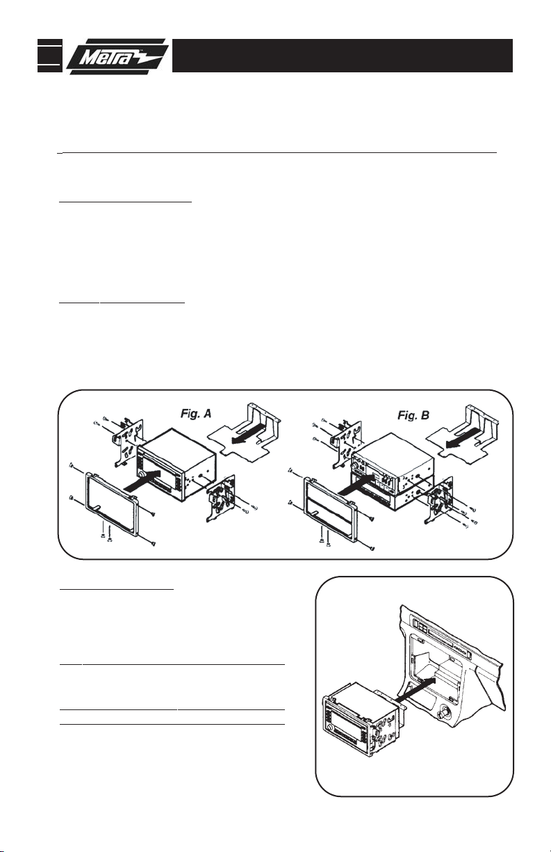
3b
DOUBLE DIN RADIO PROVISION
STACKED ISO UNITS PROVISION
*Note: Refer also to the instructions included with the aftermarket radio.
1
Disconnect the negative battery terminal to prevent an accidental short circuit.
DOUBLE-DIN HEAD UNITS: Cut and remove the dividing rib from the radio opening. Cut and
2
remove all mounting tabs on the ISO Brackets, align the holes in the Brackets with the holes
in the head unit and secure with the screws included with the unit. Slide the Rear Support
under the unit. Position the Radio Housing over the unit and mount to the ISO Brackets
Tra y
with (4) #6 x 1/4" Flat-head Screws supplied and to the Rear Support Tray with (2) #6 x
1/4" Flat-head Screws supplied (Fig. A). Skip to Final Assembly on page 11 for Step 4.
ACK HEAD UNITS:
ISO ST
3
holes in the Brackets with the holes in the head units and secure with the screws included with
the units. Slide the
units and mount to the ISO Brackets with (4) #6 x 1/4" Flat-head Screws supplied and to the
Rear Support Tray with (2) #6 x 1/4" Flat-head Screws supplied (Fig. B). Skip to Final
Assembly on page 11 for Step 4.
3b
Cut and remove all mounting tabs on the ISO Brackets, align the
Rear Support Tray under the units. Position the Radio Housing over the
CCORD 1994-97, CL:
A
Bracket (mounted to the bottom of the Rear
Support Tray) to the rear support provision in
the sub-dash with (2) bolts previously
removed. (
CRV
Snap the head unit/trim bezel assembly into
the sub- dash. (
CCORD 1990-93,
A
LUDE 1992-96, INTEGRA, OASIS, VIGOR, TL:
Snap the head unit/kit assembly into the subdash.
Mount the head unit/kit assembly to the subdash with (4) screws previously removed in
step #1. (
Skip to Final Assembly on page 11.)
, PRELUDE 1997-01, CIVIC 1999-00:
Skip to Final Assembly on page 11.)
ACCORD 1998-02,
Skip to Final Assembly on page 11.)
Secure the Mounting
ODYSSEY 1995-98, PRE-
YSSEY 1999-02:
OD
10
5
Page 13

95-7801 FINAL ASSEMBLY
Step 4.
FINAL ASSEMBLY
A
(A) Strip wire ends back 1/2"
B
B) Twist ends together
C) Solder
C
D
Locate the factory wiring harness in the dash. Metra recommends using the
1
proper mating adapter and making connections as shown. (Isolate and individually tape off the ends of any unused wires to prevent electrical short circuit.)
Re-connect the negative battery terminal and test the unit for proper operation.
2
Reassemble radio and dash assemblies in reverse order of disassembly.
3
D) Tape
FINAL WIRING CONNECTIONS
Make wiring connections using the EIA color code chart shown below and the instructions included with the
head unit. Metra recommends making connections as shown below; Strip, Splice, Solder, Tape. Isolate and
individually tape off ends of any unused wires to prevent electrical short circuit.
METRA / EIA WIRING CODE
12V Ignition / Acc. . . . . . . . . . Red
12V Batt / Memory. . . . . . . . . Yellow
Ground. . . . . . . . . . . . . . . . . . Black*
Power Antenna. . . . . . . . . . . . Blue
Amp Turn-On . . . . . . . . . . . . . Blue / White
Amp Ground. . . . . . . . . . . . . . Black / White
Illumination . . . . . . . . . . . . . . Orange
. . . . . . . . . . . . . . . . . Orange / White
Dimmer
Right Front (+) . . . . . . . . . . . . Gray
Right Front (-). . . . . . . . . . . . . Gray/ Black
Left Front (+) . . . . . . . . . . . . . White
Left Front (-). . . . . . . . . . . . . . White / Black
Right Rear (+) . . . . . . . . . . . . Violet
Right Rear (-) . . . . . . . . . . . . . Violet / Black
Left Rear (+) . . . . . . . . . . . . . Green
Left Rear (-) . . . . . . . . . . . . . . Green / Black
*NOTE: When a Black wire is not present, ground radio to vehicle chassis.
All colors may not be present on all leads due to manufacturer’s specifications.
11
Page 14

95-7801
NOTES
12
Page 15

95-7801
NOTES
13
Page 16

95-7801 INSTRUCTIONS
1-800-221-0932
. 04/21/08 © COPYRIGHT 2001-2008 METRA ELECTRONICS CORPORA
REV
www.metraonline.com
TION INST95-7801
 Loading...