

Page 1
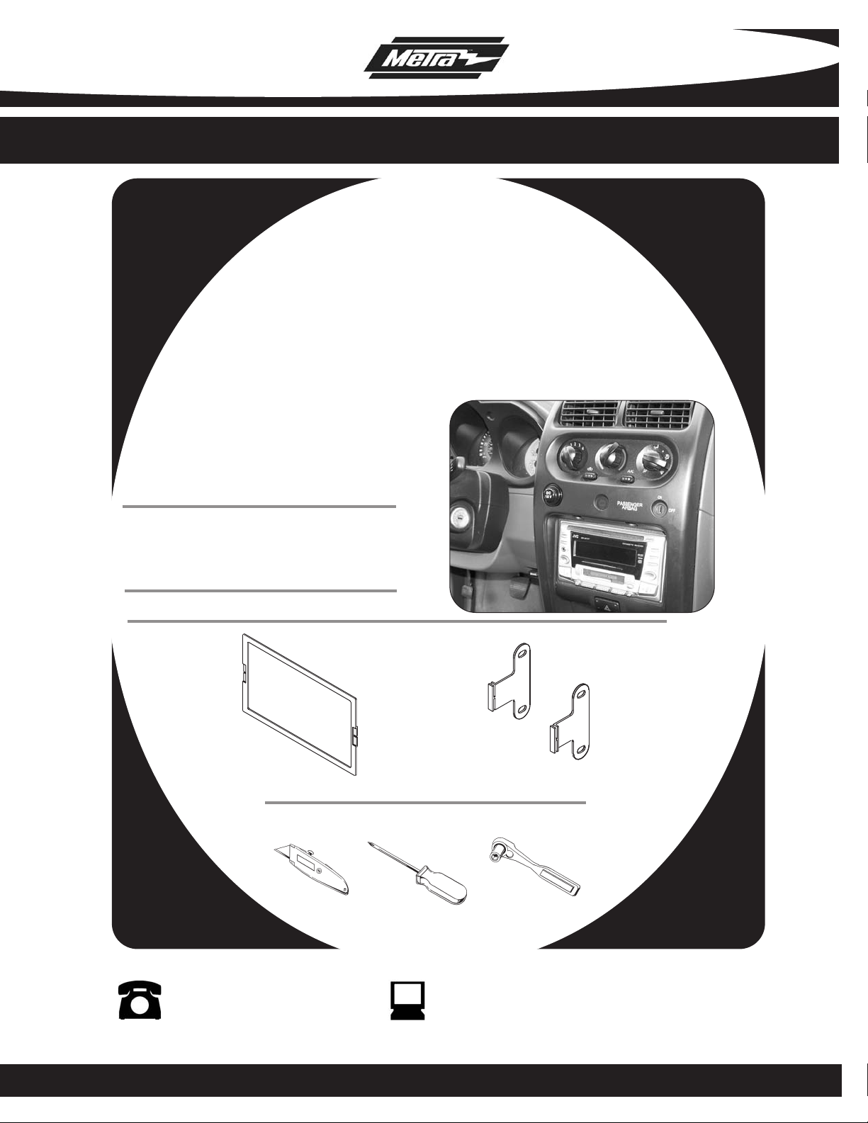
INSTALLATION INSTRUCTIONS FOR PART 95-7417
APPLICA TIONS
INFINITI 1996-1999 I-30
MERCURY 1993-2002 Villager
NISSAN 1995-1998 200SX/240SX
1998-2001 Altima / 1998-2004 Frontier
1995-2003 Maxima / 1996-2004 Pathfinder/QX4 1997-2000
1993-2003 Quest / 1995-1999 Sentra
2000-2004 Xterra
95-7417
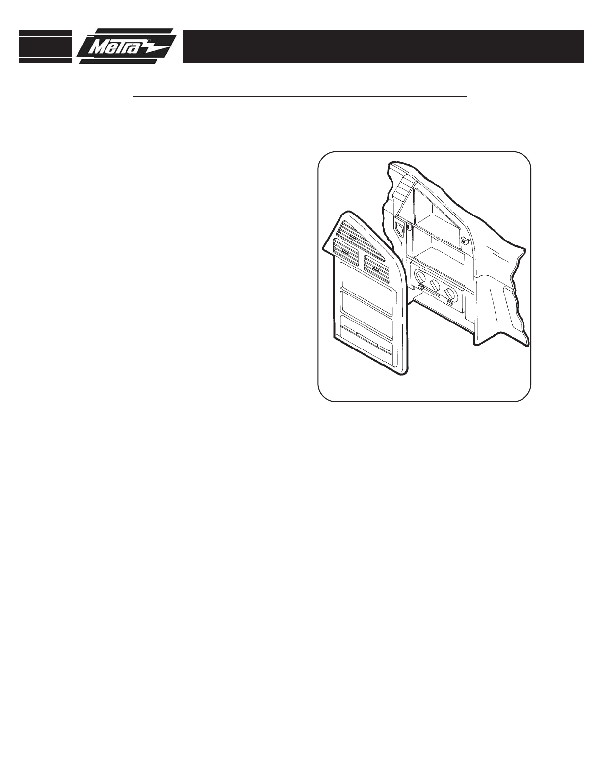
KIT FEATURES
• DDIN Head Unit Provision
• Stacked ISO DIN Head Unit Provision
KIT COMPONENTS
A) DDIN Trim plate B) DDIN Brackets
A
Cutting Tool • Phillips Screwdriver • Socket Wrench
B
TOOLS REQUIRED:
1-800-221-0932 www.metraonline.com
© COPYRIGHT 2004-2009 METRA ELECTRONICS CORPORATION
Page 2
95-7417
K
NOWLEDGE IS POWER
Enhance your installation and fabrication skills
by enrolling in the most recognized and respected
mobile electronics school in our industry.
Log onto www.installerinstitute.com
or call 800-354-6782 for more information
and take steps toward a better tomorrow.
TABLE OF CONTENTS
Dash Disassembly
1996-1999 Infiniti I-30 ................................................................. 1
1993-1995 Mercury Villager /1993-1995 Nissan Quest............... 2
1996-1998 Mercury Villager/ 1996-1998 Nissan Quest............... 3
1999-2002 Mercury Villager /1999-2003 Nissan Quest................4
1995-1999 Nissan Sentra /1995-1998 200 SX............................. 5
1995-1998 Nissan 240 SX............................................................ 6
1998-2001 Nissan Altima............................................................. 7
1998-2001 Nissan Frontier/2000-2001 Nissan Xterra ................. 8
2002-2004 Nissan Frontier/2002-2004 Nissan Xterra ................. 9
1995-1999 Nissan Maxima......................................................... 10
2000-2003 Nissan Maxima......................................................... 11
*
1996-2000 Nissan Pathfinder/QX4 1997-2000........................... 12
2001-2004 Nissan Pathfinder..................................................... 13
Fits all models EXCEPT the Bose and Comfort & Convenience pkgs.
*
Assembly
Kit
Double DIN Head Unit Provision.................................................. 14
Stacked ISO DIN Head Unit Provision ......................................... 15
Final
Assembly ............................................................................16
CAUTION:
Do not cycle the key when removing a dash with passenger
airbag ON/OFF switch.
Page 3
95-7417
1996-1999 INFINITI I-30
Disconnect the negative battery
1
terminal to prevent an accidental
short circuit.
2
Unclip and remove the shift lever
trim panel and remove the (2)
screws exposed.
Remove (1) screw to the left of the
3
ashtray then unclip and remove the
ashtray assembly.
DASH DISASSEMBLY
Unclip and remove the clock/vent
4
assembly.
Remove (4) screws securing the
5
radio.
1
Page 4
95-7417
1993-1995 MERCURY VILLAGER
1993-1995 NISSAN QUEST
1
Disconnect the negative battery
terminal to prevent an accidental
short circuit.
Remove (1) screw above the climate
2
controls.
Unclip and remove the radio trim
3
panel.
Remove (4) screws securing the
4
radio.
DASH DISASSEMBLY
2
Page 5

95-7417
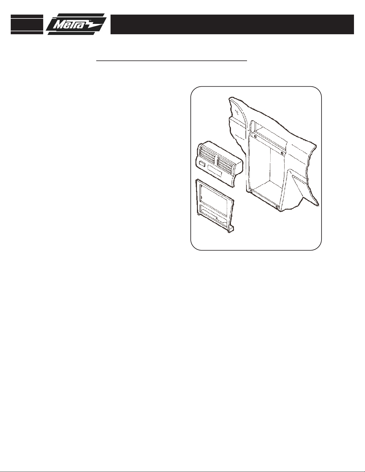
1996-1998 MERCURY VILLAGER
1996-1998 NISSAN QUEST
Disconnect the negative battery
1
terminal to prevent an accidental
short circuit.
Remove (4) plastic screws and
2
screw anchors from the base of the
storage compartment then remove
the compartment.
Remove (2) Phillips screws from the
3
base of the radio trim panel.
DASH DISASSEMBLY
Remove (2) Phillips screws from
4
above the radio opening.
Remove the ashtray.
5
Remove (4) screws securing the
6
radio.
3
Page 6
95-7417
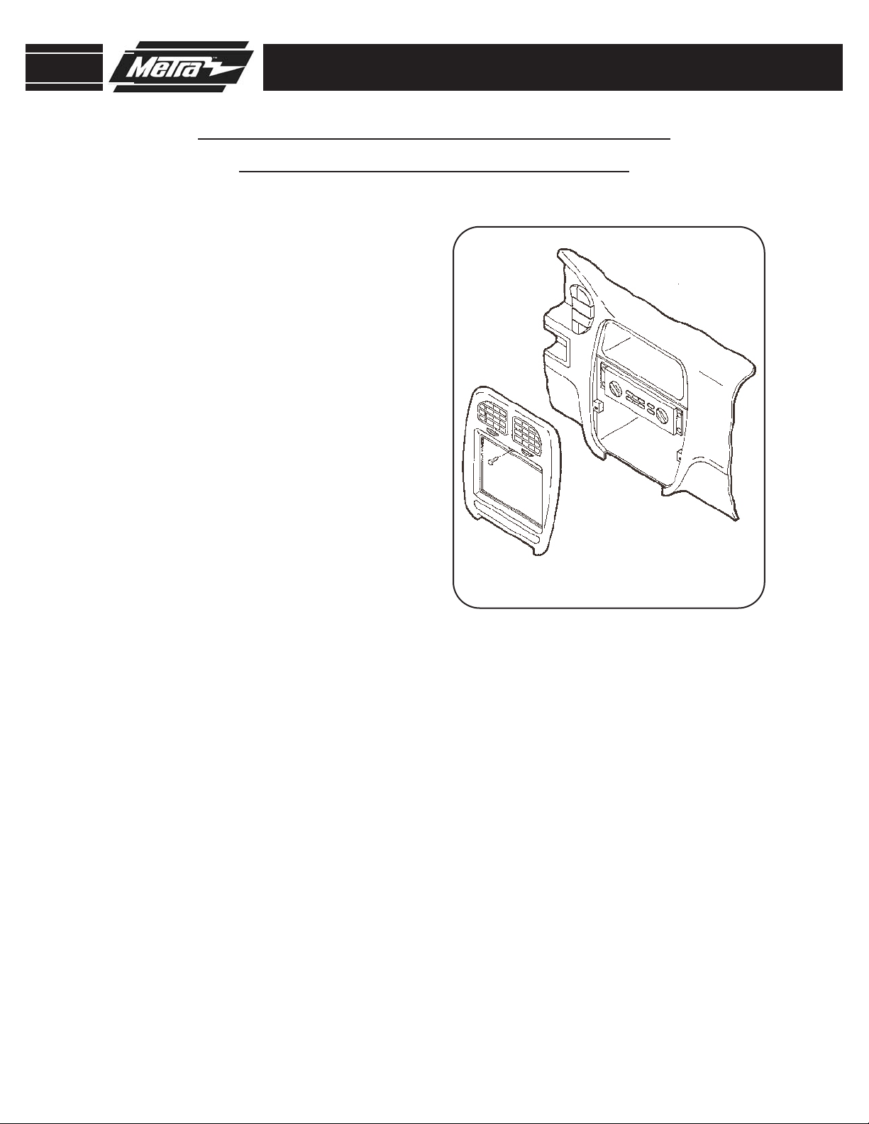
1999-2002 MERCURY VILLAGER
1999-2003 NISSAN QUEST
Disconnect the negative battery
1
terminal to prevent an accidental
short circuit.
Open the ashtray/cupholder assem-
2
bly and depress the retaining clips
on each side to remove.
3
Remove (2) Phillips screws from
each side of the ashtray/cupholder.
DASH DISASSEMBLY
4
Remove (4) plastic rivets from the
lower pocket and slide the pocket
back. Note: It is not necessary to
fully remove the pocket.
5
Unclip the dash trim panel and
remove.
6
Remove (4) Phillips screws securing
the radio.
4
Page 7

95-7417
1995-1999 NISSAN SENTRA
1995-1998 200 SX
Disconnect the negative battery
1
terminal to prevent an accidental
short circuit.
Unclip and remove the dummy plate
2
above the climate controls.
Remove (1) Phillips screw from
3
behind dummy plate.
4
Unclip and remove radio trim panel.
DASH DISASSEMBLY
Remove (4) Phillips screws securing
5
radio.
5
Page 8

95-7417
1995-1998 NISSAN 240 SX
Disconnect the negative battery ter-
1
minal to prevent an accidental short
circuit.
Unclip and remove the climate con-
2
trol trim panel and remove the (2)
exposed behind.
Unclip and remove the shift lever
3
trim panel and remove the (2) screws
exposed behind.
DASH DISASSEMBLY
Remove the ashtray and (1) Phillips
4
screw exposed in the ashtray cavity.
5
Unclip and remove the radio trim
panel, factory radio and pocket
assembly.
6
Page 9

95-7417
1998-2001 NISSAN ALTIMA
Disconnect the negative battery terminal
1
to prevent an accidental short circuit.
Unclip the shift lever trim panel and
2
remove (2) Phillips screws at the base
of the radio trim panel.
3
Remove (2) Phillips screws above the
radio opening.
4
Unclip and remove the radio trim panel.
5
Remove (4) Phillips screws securing the
radio.
DASH DISASSEMBLY
1
7
Page 10

95-7417
1998-2001 NISSAN FRONTIER
2000-2001 NISSAN XTERRA
Disconnect the negative battery terminal
1
to prevent an accidental short circuit.
Remove the ashtray and the (2) Phillips
2
screws exposed in the ashtray cavity.
3
Unclip and remove the radio trim panel.
4
Remove (4) Phillips screws securing the
radio.
DASH DISASSEMBLY
8
Page 11

95-7417
2002-2004 NISSAN FRONTIER
2002-2004 NISSAN XTERRA
Disconnect the negative battery terminal
1
to prevent an accidental short circuit.
Unclip and remove the shift lever trim
2
panel.
3
Remove (2) Phillips screws exposed in
the shift lever cavity.
4
Remove (2) Phillips screws under the
climate control.
DASH DISASSEMBLY
5
Unclip and remove the radio trim panel.
6
Remove (4) Phillips screws securing the
radio.
9
Page 12

95-7417
1995-1999 NISSAN MAXIMA
Disconnect the negative battery terminal
1
to prevent an accidental short circuit.
Unclip the shift lever trim panel.
2
3
Remove the (2) Phillips screws at the
base of the radio trim panel.
4
Remove (1) Phillips screw to the left of
the ashtray and unclip the ashtray
assembly.
DASH DISASSEMBLY
5
Unclip and remove the clock/vent
assembly.
6
Remove (4) Phillips screws securing the
radio.
10
Page 13

95-7417
2
4
5
5
5
5
2000-2003 NISSAN MAXIMA
Disconnect the negative battery terminal
1
to prevent an accidental short circuit.
Unclip and remove the vent/radio trim
2
panel.
assembly will be removed without the
trim panel.
3
Remove the ashtray insert and (1)
Phillips screw exposed behind.
Note: For Bose systems the vent
DASH DISASSEMBLY
4
Unclip and remove the shift lever/ashtray trim panel.
5
Remove (2) Phillips screws above the
radio and (2) Phillips screws below the
climate control panel then remove the
radio/climate control assembly.
11
Page 14

95-7417
DASH DISASSEMBLY
1996-2000 NISSAN PATHFINDER/QX4 1997-2000
Disconnect the negative battery terminal
1
to prevent an accidental short circuit.
Remove (2) Phillips screws from the
2
base of the radio trim panel.
3
Unclip and remove the radio trim panel.
4
Remove (4) Phillips screws securing
radio.
12
Page 15

95-7417
2001-2003 NISSAN PATHFINDER
Disconnect the negative battery terminal
1
to prevent an accidental short circuit.
Unclip and remove the vent/clock
2
assembly.
3
Remove (2) Phillips screws from the top
of the radio trim panel then remove the
panel.
4
Remove (4) Phillips screws securing
radio.
(Figure A)
(Figure B)
(Figure C)
DASH DISASSEMBLY
A
B
C
13
Page 16

95-7417
DOUBLE DIN HEAD UNIT PROVISION
Slide the appropriate bracket into
1
the trim plate aligning the holes in
the trim plate to the clips on the
bracket. (
Attach the factory mounting brackets
2
and the 95-7417 DDIN trim
plate/bracket assembly to the DDIN
head unit with the screws supplied
with the unit. (
Figure A)
Figure B)
KIT ASSEMBLY
A
B
14
Page 17

95-7417
KIT ASSEMBLY
STACKED ISO DIN HEAD UNIT PROVISION
A
Slide the appropriate bracket into
1
the trim plate aligning the holes in
the trim plate to the clips on the
bracket. (
Attach the factory mounting brackets
2
and the 95-7417 DDIN trim
plate/bracket assembly to the
stacked ISO DIN head units with the
screws supplied with the units.
Figure B)
(
Figure A)
B
15
Page 18

95-7417
FINAL ASSEMBLY
FINAL ASSEMBLY
Locate the factory wiring harness in the dash and make the connection as shown.
1
Metra recomends using the proper mating adapter and making the connections as
shown. (Isolate and individually tape off the ends of any unused wires to prevent
electrical short circuit.)
Re-connect the negative battery terminal and test the unit for proper operation.
2
3
Reassemble radio and dash assemblies in reverse order of disassembly.
FINAL WIRING CONNECTIONS
Make wiring connections using the EIA color code chart shown below and the instructions included with the head
unit. Metra recommends making connections as shown below; Strip, Splice, Solder, Tape. Isolate and individually
tape off ends of any unused wires to prevent electrical short circuit.
A
B
C
D
A) Strip wire ends back 1/2"
B) Twist ends together
C) Solder
D) Tape
METRA / EIA WIRING CODE
12V Ignition / Acc . . . Red
12V Batt / Memory . . Yellow
Ground . . . . . . . . . . . Black*
Power Antenna . . . . . Blue
Amp Turn-On . . . . . . Blue / White
Amp Ground . . . . . . . Black / White
Illumination. . . . . . . . Orange
Right Front (+) . . . . . Gray
Right Front (-) . . . . . . Gray / Black
Left Front (+) . . . . . . White
Left Front (-) . . . . . . . White / Black
Right Rear (+). . . . . . Violet
Right Rear (-) . . . . . . Violet / Black
Left Rear (+). . . . . . . Green
Dimmer . . . . . . . . . . Orange / White
*NOTE: When Black a wire is not present, ground radio to vehicle chassis.
All colors may not be present on all leads due to manufacturer’s specifications.
Left Rear (-) . . . . . . . Green / Black
16
Page 19

95-7417
NOTES
17
Page 20

95-7417 INSTRUCTIONS
1-800-221-0932 www.metraonline.com
REV. 07/28/09 © COPYRIGHT 2004-2009 METRA ELECTRONICS CORPORATION INST95-7417
 Loading...