

Page 1
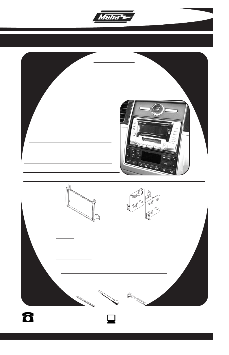
INSTALLATION INSTRUCTIONS FOR PART 95-5810
APPLICATIONS
LINCOLN Town Car
2003-2011
95-5810
KIT FEATURES
• Double DIN Radio Provision
• Stacked ISO Mount Units Provision
KIT COMPONENTS
A) Double DIN Trim Plate B) Double DIN Brackets
A
WIRING AND ANTENNA CONNECTIONS (Sold Separately)
Harness:
• 70-5520 - Ford harness 2003-up
• 70-5521 - Ford amp harness 2003-up
Antenna Adapter:
• Not required
TOOLS REQUIRED:
Small Flat Blade Screwdriver/ Panel Removal Tool
• Socket Set
1-800-221-0932
© COPYRIGHT 2007-2009 METRA ELECTRONICS CORPORATION
B
www.metraonline.com
Page 2
95-5810
TABLE OF CONTENTS
Dash Disassembly
- LINCOLN Town Car 2003-2011 . . . . . . . . . . . . . . . . . . . . . . . . . . . . . . . . . . . . . 1
Kit Assembly
- Double DIN Radio Provision . . . . . . . . . . . . . . . . . . . . . . . . . . . . . . . . . . . . . . . 2
- Stacked ISO Mount Units Provision . . . . . . . . . . . . . . . . . . . . . . . . . . . . . . . . . 3
Final Assembly
*Note:
Refer also to the instructions included with the aftermarket radio.
. . . . . . . . . . . . . . . . . . . . . . . . . . . . . . . . . . . . . . . . . . 4
KNOWLEDGE IS POWER
Enhance your installation and fabrication skills by
enrolling in the most recognized and respected
mobile electronics school in our industry.
Log onto www.installerinstitute.com or call
800-354-6782 for more information and take
steps toward a better tomorrow.
Page 3
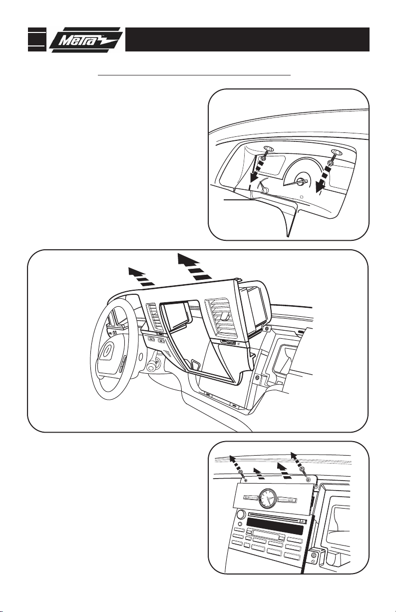
95-5810 DASH DISASSEMBLY
10
0
20
30
40
50
60
70
80
90
100
100
60
20
140
180
110
120
P
C
H
R
N
2
1
MPH
0.0
MILES
LINCOLN
LINCOLN TOWN CAR 2003-2011
1
Disconnect the negative battery ter-
minal to prevent an accidental short
circuit.
2
Remove (2) 7mm bolts facing upward
above instrument cluster/gauges.
(Figure A)
3
Carefully unsnap and remove dash
panel surrounding radio and instrument cluster/gauges.
B
(Figure B)
A
4
Remove (2) 7mm bolts above clock
panel and remove panel).
5
Remove (4) 7mm bolts securing radio.
(Figure C)
Continue to kit assembly.
C
1
Page 4

95-5810 KIT ASSEMBLY
DOUBLE DIN RADIO PROVISION
*Note: Refer also to the instructions included with the aftermarket radio.
A
1
Attach the Double DIN brackets to the
aftermarket radio using the screws
supplied with the radio.
2
Place the Double DIN trim plate over
the radio face then secure the entire
assembly into the sub dash.
Continue to final assembly.
(Figure A)
(Figure B)
B
2
Page 5

95-5810 KIT ASSEMBLY
STACKED ISO MOUNT UNITS PROVISION
*Note: Refer also to the instructions included with the aftermarket radio.
A
1
Attach the Double DIN brackets to the
aftermarket units using the screws
supplied with the units.
2
Place the Double DIN trim plate over
the unit faces then secure the entire
assembly into the sub dash.
Continue to final assembly.
(Figure A)
(Figure B)
B
3
Page 6
95-5810 FINAL ASSEMBLY
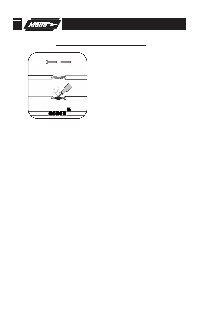
FINAL ASSEMBLY
A
(A) Strip wire ends back 1/2"
B
B) Twist ends together
C) Solder
C
D
Locate the factory wiring harness in the dash. Metra recommends using the
1
proper mating adapter and making connections as shown. (Isolate and individually tape off the ends of any unused wires to prevent electrical short circuit.)
2
Re-connect the negative battery terminal and test the unit for proper operation.
Reassemble radio and dash assemblies in reverse order of disassembly.
3
D) Tape
FINAL WIRING CONNECTIONS
Make wiring connections using the EIA color code chart shown below and the instructions included with the
head unit. Metra recommends making connections as shown below; Strip, Splice, Solder, Tape. Isolate and
individually tape off ends of any unused wires to prevent electrical short circuit.
METRA / EIA WIRING CODE
12V Ignition / Acc . . . . . . . . . . Red
12V Batt / Memory. . . . . . . . . Yellow
Ground. . . . . . . . . . . . . . . . . . Black*
Power Antenna. . . . . . . . . . . . Blue
Amp Turn-On . . . . . . . . . . . . . Blue / White
Amp Ground. . . . . . . . . . . . . . Black / White
Illumination . . . . . . . . . . . . . . Orange
Dimmer . . . . . . . . . . . . . . . . . Orange / White
Right Front (+) . . . . . . . . . . . . Gray
Right Front (-). . . . . . . . . . . . . Gray/ Black
Left Front (+) . . . . . . . . . . . . . White
Left Front (-). . . . . . . . . . . . . . White / Black
Right Rear (+) . . . . . . . . . . . . Violet
Right Rear (-) . . . . . . . . . . . . . Violet / Black
Left Rear (+) . . . . . . . . . . . . . Green
*NOTE: When a Black wire is not present, ground radio to vehicle chassis.
All colors may not be present on all leads due to manufacturer’s specifications.
4
Page 7

95-5810
NOTES
5
Page 8

95-5810 INSTRUCTIONS
1-800-221-0932
REV. 11/18/10 © COPYRIGHT 2007-2009 METRA ELECTRONICS CORPORATION INST95-5810
www.metraonline.com
 Loading...