

Metra 99-5857B Instructions
INSTALLATION INSTRUCTIONS
99-585 7B
Ford Ranger † 2019-Up
Visit MetraOnline.com for more detailed information about the product and up-to-date vehicle
specific applications
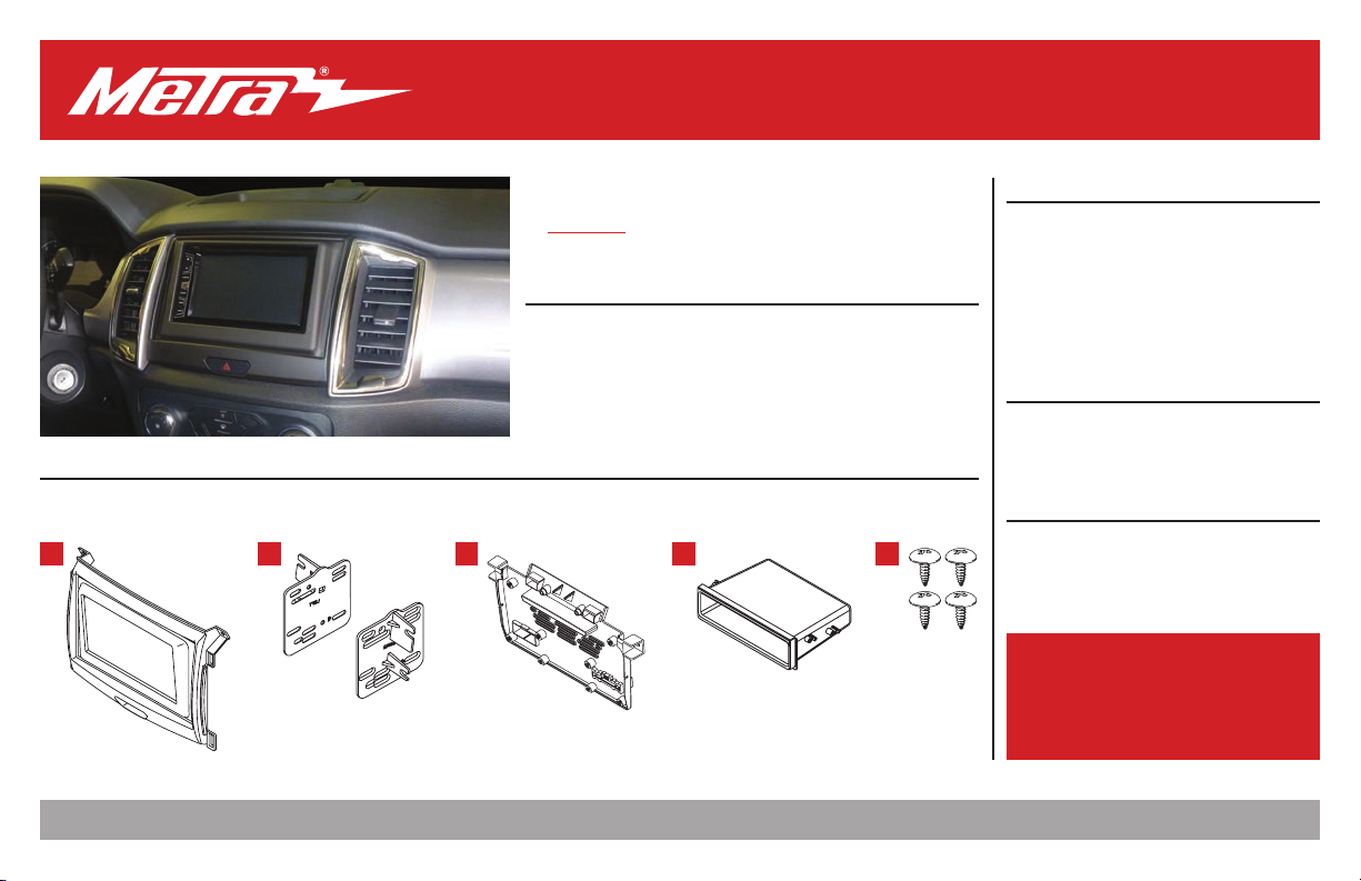
KIT FEATURES
• ISO DIN radio provision with pocket
• ISO DDIN radio provision
• Painted scratch-resistant matte black
† With 4.2-inch display screen
KIT COMPONENTS
• A) Radio bezel (with trim) • B) Radio brackets • C) Back panel • D) Pocket • E) Phillips screws (4)
A B C D E
®
Metra. The World’s Best Kits.
MetraOnline.com © COPYRIGHT 2020 METRA ELECTRONICS CORPORATION REV. 3/12/20 INST99-5857B
TABLE OF CONTENTS
Dash Disassembly ...............................................2-3
Kit Preparation ...................................................4-5
Kit Assembly
–ISO DIN radio provision with pocket ..................6
–ISO DDIN radio provision .....................................7
WIRING & ANTENNA CONNECTIONS (sold separately)
Wire harness: • AXTC-FD2
Antenna adapter: • 40-EU10
TOOLS REQUIRED
• 9/32” socket wrench • Panel removal tool
• Phillips screwdriver
• T-6 & T-8 Torx screwdriver
Attention! Let the vehicle sit with the key
out of the ignition for a few minutes before
removing the factory radio. When testing the
aftermarket equipment, ensure that all factory
equipment is connected before cycling the
key to ignition.
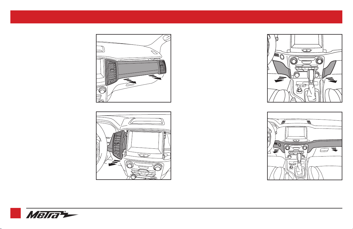
DASH DISASSEMBLY
Note: Figures A-F show the 8” display model
radio for illustration purposes only.
1. Unclip and remove the passenger side
a/c vent & dash panel assembly.
(Figure A)
2. Unclip and remove the a/c vent to the
left of the radio. (Figure B)
3. Unclip and remove the lower trim panels
to the left and right of the climate
controls. (Figure C)
4. Unclip and remove the lower dash panel.
(Figure D)
Continued on the next page
(Figure A) (Figure C)
(Figure B)
(Figure D)
2
386.257.1187 | MetraOnline.com

DASH DISASSEMBLY
(CON T.)
5. Remove (2) 9/32” screws securing the
power port panel, then unclip, unplug,
and remove the panel. (Figure E)
6. Remove (6) 9/32” screws securing the
radio & climate control panel, then
unplug and remove. (Figure F)
7. Remove (4) 9/32” screws securing the
radio display, then unplug and remove.
(Figure G)
8. Remove (4) 9/32” screws securing the
radio chassis. Slide the chassis out, then
unplug and remove. (Figure H)
Continue to Kit Preparation
(Figure G)(Figure E)
(Figure H)(Figure F)
REV. 3/12/2020 INST99-5857B
3
 Loading...