

Metra 99*5853CH Installation Manual
99-5853CH
INSTALLATION INSTRUCTIONS
Ford Mustang (†) 2010-2014
With single zone, manual climate control
†
Visit MetraOnline.com for more detailed information about the product and up-to-date vehicle
specific applications
KIT FEATURES
• ISO DIN radio provision with pocket
• ISO DDIN radio provision
• Included interface for climate and steering wheel functions
• Painted charcoal with a matte black center
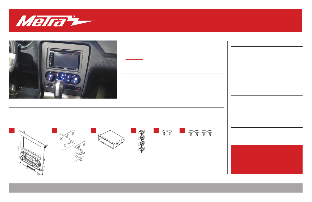
KIT COMPONENTS
• A) Radio trim panel • B) Radio brackets
• F) (4) #8 x 3/8” Phillips truss-head screws • G) Wiring harness (not shown) • H) Antenna adapter (not shown)
A B C
Metra. The World’s Best Kits.
•C) Pocket • D) (4) Panel clips • E) (2) #8 x 3/8” Phillips pan-head screws
ED
®
MetraOnline.com © COPYRIGHT 2019 METRA ELECTRONICS CORPORATION REV. 12/6/19 INST99-5853CH
TABLE OF CONTENTS
Dash Disassembly ..................................................2
Kit Assembly
–ISO DIN radio provision with pocket .................. 3
–ISO DDIN radio provision .....................................4
Axxess Interface Installation .............................5-11
Final Assembly .......................................................9
WIRING & ANTENNA CONNECTIONS
Wiring Harness: Axxess interface built into kit
Antenna Adapter: Included with kit
Steering wheel control interface: Included with kit
TOOLS REQUIRED
F
• Panel removal tool • Phillips screwdriver
• 9/32” socket wrench
Attention! Let the vehicle sit with the key
out of the ignition for a few minutes before
removing the factory radio. When testing the
aftermarket equipment, ensure that all factory
equipment is connected before cycling the
key to ignition.
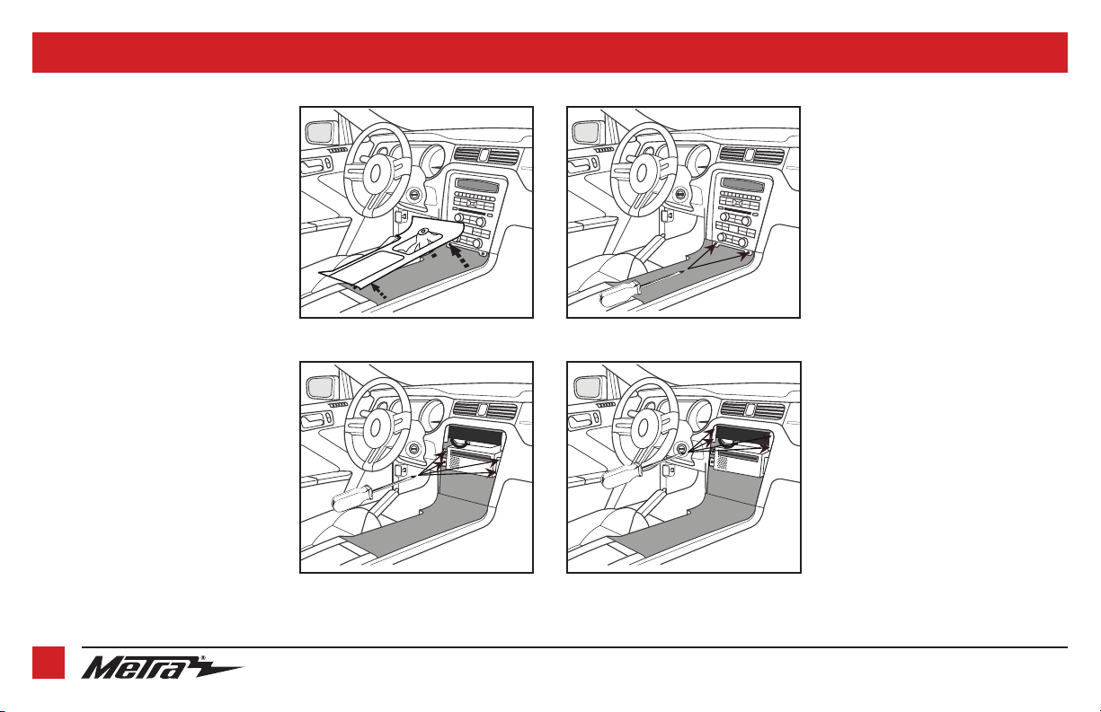
1. Unclip and remove the trim panel
surrounding the shifter, including the
cup holders. (Figure A)
2. Remove (2) 9/32” screws from the
bottom of the radio/climate control
panel, then unclip and remove the
panel. (Figure B)
3. Remove (4) Phillips screws securing the
radio chassis to the vehicle. Slide the
chassis out, then unplug and remove.
(Figure C)
4. Remove (4) Phillips screws securing the
radio display to the vehicle. Slide the
display out, then unplug and remove.
(Figure D)
Continue to Kit Assembly
DASH DISASSEMBLY
(Figure B)(Figure A)
(Figure C) (Figure D)
2
1.800.221.0932 | MetraOnline.com
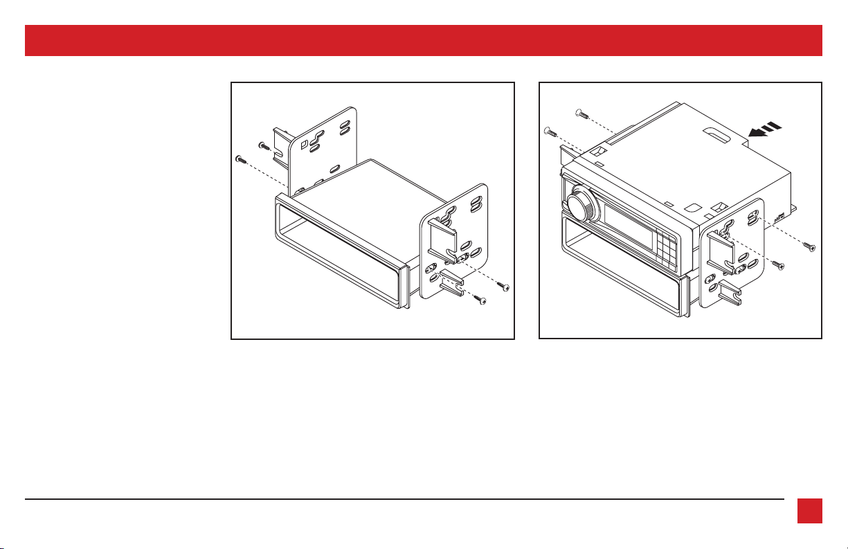
ISO DIN radio provision with pocket
1. Attach the pocket to the radio brackets
using (4) #8 x 3/8” Phillips truss-head
screws provided. (Figure A)
2. Remove the metal DIN sleeve and trim
ring from the aftermarket radio.
3. Slide the radio into the bracket/pocket
assembly, then secure it using screws
supplied with the radio. (Figure B)
Continue to Axxess
Interface Installation
KIT ASSEMBLY
(Figure A) (Figure B)
REV. 12/6/2019 INST99-5853CH
3
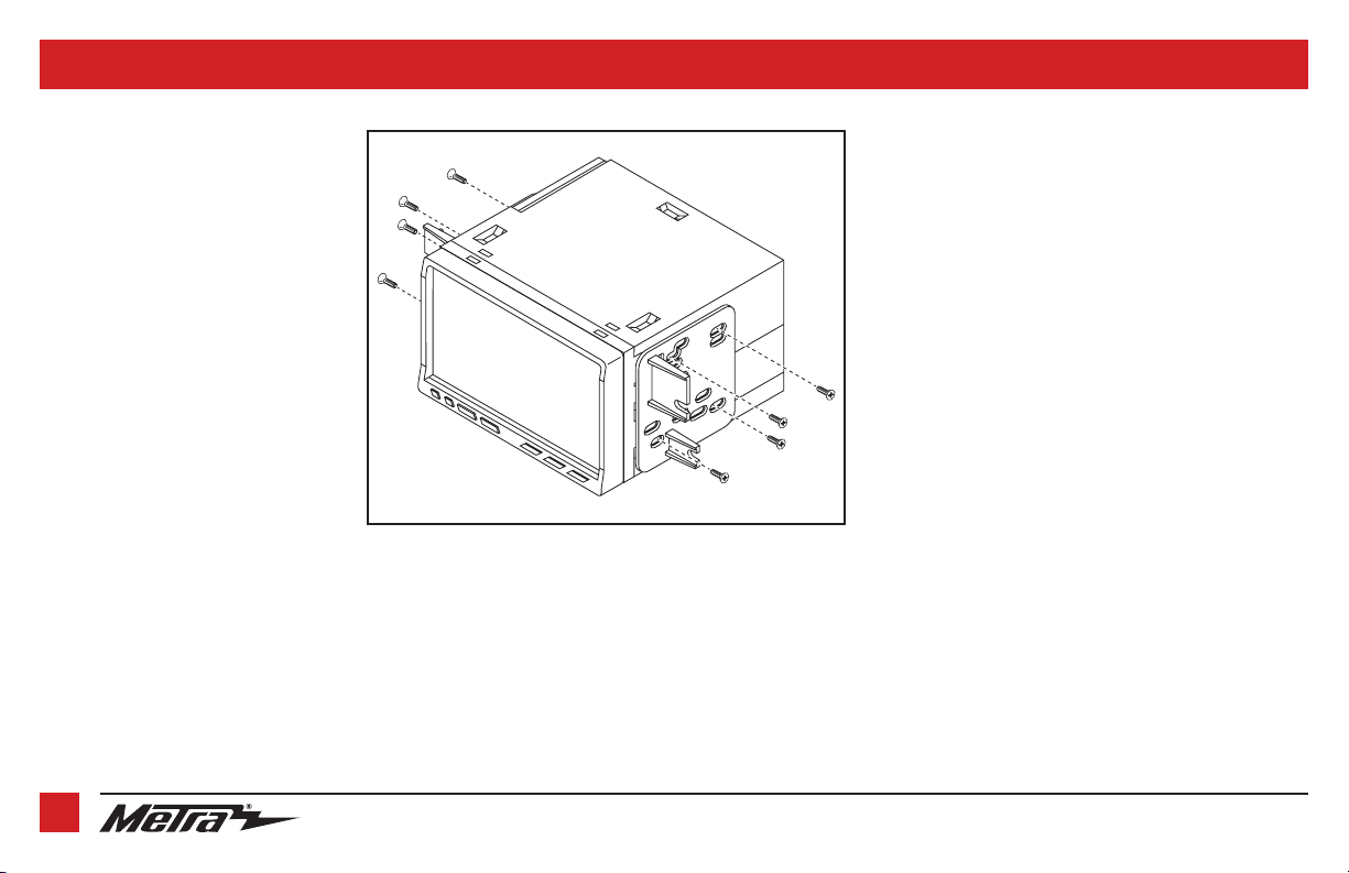
ISO DDIN radio provision
1. Attach the radio brackets to the radio
using screws supplied with the radio.
(Figure A)
Continue to Axxess
Interface Installation
KIT ASSEMBLY
(Figure A)
4
1.800.221.0932 | MetraOnline.com

AXXESS INTERFACE INSTALLATION
INTERFACE FEATURES
• Provides accessory power (12-volt 10-amp)
• Retains R.A.P. (retained accessory power)
• Provides illumination, parking brake, reverse, and speed sense outputs
• Retains audio controls on the steering wheel
• Can be used in both amplified and non-amplified models
• Retains balance and fade
• Micro-B USB updatable
INTERFACE COMPONENTS
• Axxess interface (built into kit)
• 5853 harness
• 16-pin harness
• 3.5mm adapter
TABLE OF CONTENTS
Connections ...........................................................................................................................................6 -7
Installation ...............................................................................................................................................8
Programming ........................................................................................................................................... 8
Configuration menu ............................................................................................................................9-11
TOOLS REQUIRED
• Crimping tool and connectors, or solder gun, solder, and heat shrink
• Tape • Wire cutter • Zip ties
REV. 12/6/2019 INST99-5853CH
5
CONNECTIONS
From the 16-pin harness to the aftermarket radio, connect the:
• Red wire to the accessory wire.
•
Blue/White wire to the amp turn on wire, if the vehicle is equipped with a Shaker/Shaker-Pro
sound system
• Orange/White to the illumination wire (if applicable).
• Gray wire to the right front positive speaker output.
• Gray/Black wire to the right front negative speaker output.
• White wire to the left front positive speaker output.
• White/Black wire to the left front negative speaker output.
The following (3) wires are only for multimedia/navigation radios that require these wires.
• Blue/Pink wire to the VSS/speed sense wire.
• Green/Purple wire to the reverse wire.
• Light Green wire to the parking brake wire
• Tape off and disregard the following (5) wires, they will not be used in this application:
Brown, Green, Green/Black, Purple, Purple/Black
.
From the 5853 harness to the aftermarket radio, connect the:
• Black wire to the ground wire.
• Yellow wire to the battery wire.
• Green wire to the left rear positive speaker output.
• Green/Black wire to the left rear negative speaker output.
• Purple wire to the right rear positive speaker output.
• Purple/Black wire to the right rear negative output.
• Disregard the Red and White RCA jacks labeled “RSE/SYNC®/SAT”, they will not be used in
this application.
• Disregard the Red and White RCA jacks labeled “FROM 3.5”, they will not be used in this
application.
• Tape off and disregard the following (3) wires, they will not be used in this application:
Blue, Blue/White, Red.
• Disregard the DIN jack, it will not be used in this application.
Continued on the next page
6
1.800.221.0932 | MetraOnline.com

CONNECTIONS (CONT.)
For models
with
a Shaker system:
• Connect the White RCA jack labeled “SUBWOOFER”, to the subwoofer out jack.
• Disregard the Red RCA jack labeled “CENTER CHANNEL”, it will not be used in this
application.
For models
with
a Shaker Pro system:
• Connect the Red RCA jack labeled “CENTER CHANNEL”, to the subwoofer out jack.
• Disregard the White RCA jack labeled “SUBWOOFER”, it will not be used in this
application.
3.5mm jack - steering wheel control retention:
The 3.5mm jack is to be used to retain audio controls on the steering wheel control.
• For the radios listed below: Connect the 3.5mm adapter, to the male 3.5mm SWC jack from the 5853
harness. Any remaining wires tape off and disregard.
•
Eclipse: Connect the steering wheel control wire, normally Brown, to the Brown/White wire of
the connector. Then connect the remaining steering wheel control wire, normally Brown/White,
to the Brown wire of the connector
Metra OE:
•
•
•
•
•
• For all other radios: Connect the 3.5mm jack into the port on the radio designated for an external
steering wheel control interface. Refer to the manual provided with the radio if in doubt as to where the
3.5mm jack goes to.
Connect the steering wheel control Key 1 wire
Kenwood or select JVC with a steering wheel control wire:
Brown
wire.
Note:
If your
Kenwood
See the instructions under changing radio type.
XITE:
Connect the steering wheel control SWC-2 wire from the radio to the
Parrot Asteroid Smart or Tablet:
and then connect the 4-pin connector from the AX-SWC-PARROT into the radio
Note:
The radio must be updated to rev. 2.1.4 or higher software.
Universal “2 or 3 wire” radio:
SWC-1, to the
referred to as Key-B or SWC-2, to the
third wire for ground, disregard this wire
Note:
After the interface has been programmed to the vehicle, refer to the manual provided with
the radio for assigning the SWC buttons. Contact the radio manufacturer for more information.
radio auto detects as a
Brown
wire of the connector. Then connect the remaining steering wheel control wire,
.
(Gray)
to the
Brown
wire.
Connect the
JVC
, manually set the radio type to
Connect the 3.5mm jack into the AX-SWC-PARROT (sold separately),
Connect the steering wheel control wire, referred to as Key-A or
Brown/White
wire of the connector. If the radio comes with a
.
Blue/Yellow
Kenwood
Brown
wire.
.
wire to the
.
REV. 12/6/2019 INST99-5853CH
7
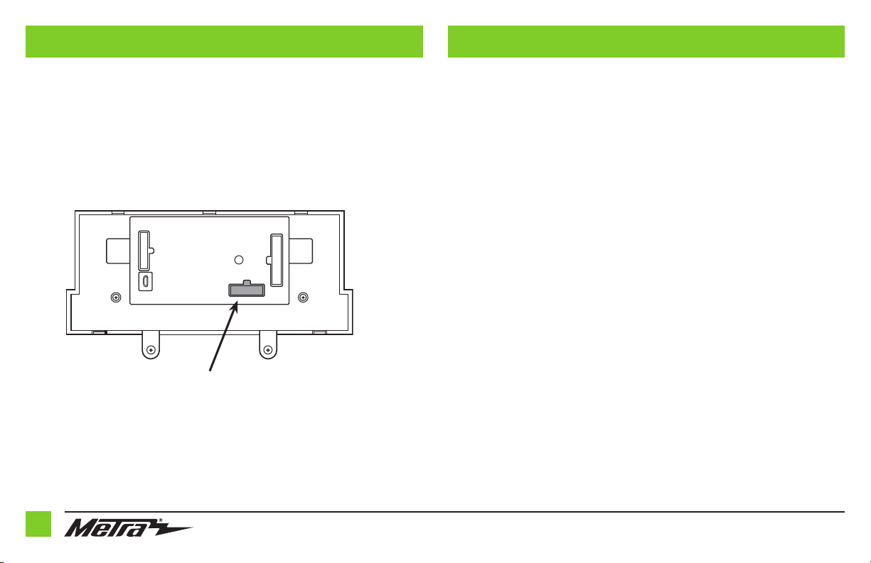
INSTALLATION PROGRAMMING
1. Connect the 16-pin harness into port A.
2. Disregard port B, it will not be used in this application..
3. Connect the 5853 harness into port C, and then to the wiring harnesses in the vehicle.
4. Port D is a Micro-B USB input for updating the interface.
A
D
Note: DO NOT CONNECT!
C
B
1. Open the driver’s door, and keep open during the programming process.
2. Cycle the ignition on and wait until the climate control lights turn blue.
Note: If the lights don’t turn blue, unplug port C from the touchscreen for a few seconds,
then try again.
3. Test all functions of the installation for proper operation, before reassembling the dash.
8
1.800.221.0932 | MetraOnline.com
 Loading...