


POTWASHER WITH GRANULATE
WD-90GR FLEX & WD-90GR HC
(translation of the original documentation)
Service manual
S/N: Valid from: 15. 05. 2011 Rev.: 2.0
4246124, 4246125


WD-90GR Rev.
1. Safety instructions ........................................................................... 1
1.1 General information ......................................................................................... 1
1.2 Transport .......................................................................................................... 1
1.3 Installation ........................................................................................................ 2
1.4 Detergent and drying agent ............................................................................. 2
1.5 Operation ......................................................................................................... 2
1.5.1 Hot water .................................................................................................. 2
1.5.2 Crushing risk ............................................................................................. 2
1.5.3 Risk of slipping .......................................................................................... 2
1.6 Cleaning ........................................................................................................... 3
1.6.1 Pressure washing ..................................................................................... 3
1.6.2 The outside of the machine ...................................................................... 3
1.6.3 Cleaning the floor ...................................................................................... 3
1.7 Repairing and servicing the dishwasher .......................................................... 4
1.7.1 Safety instructions if the machine is not functioning ................................. 4
1.8 Recycling the machine ..................................................................................... 4
2. Operational description ................................................................... 5
2.1 General information ......................................................................................... 5
2.2 Design .............................................................................................................. 6
2.3 Control panel .................................................................................................... 8
2.4 Operating principle ......................................................................................... 10
2.4.1 Starting the machine ............................................................................... 10
2.4.2 Filling the chemical wash tank ................................................................ 10
2.4.3 Heating the tank ...................................................................................... 10
2.4.4 Wash phase ............................................................................................ 10
2.4.5 Wash cycle for programmes P1, P2 and P3 ........................................... 12
2.4.6 Wash cycle for programmes P4, P5 and P6 ........................................... 12
2.4.7 Guaranteed final rinse ............................................................................ 12
2.5 Controlling the washing process .................................................................... 13
2.6 Display messages .......................................................................................... 13

WD-90GR Rev.
3. Adjustment instructions ................................................................ 14
3.1 Diagnostics function ....................................................................................... 14
3.2 Activating and using the diagnostics function ................................................ 15
3.2.1 REFERENCE VALUES .......................................................................... 16
3.2.2 Other information from the diagnostics system ...................................... 18
3.2.3 DIAGNOSIS ............................................................................................ 18
3.2.4 RELAY TEST .......................................................................................... 18
3.2.5 STATISTICS ........................................................................................... 18
3.2.6 TIME & DATE ......................................................................................... 18
3.2.7 LANGUAGE ............................................................................................ 19
3.2.8 OTHER ................................................................................................... 19
3.2.9 Resetting the filling memory ................................................................... 19
3.3 Setting up the frequency converter ................................................................ 20
3.3.1 Checking and setting the reference values ............................................. 21
3.3.2 Alarm codes frequency converter ........................................................... 22
3.3.3 Changing the frequency converter .......................................................... 22
4. Service ............................................................................................ 23
4.1 Repairs and machine maintenance ............................................................... 23
4.1.1 Periodic maintenance ............................................................................. 23
4.1.2 Machine damage .................................................................................... 23
4.2 Drive motor .................................................................................................... 24
4.2.1 Assembly ................................................................................................ 24
4.2.2 Service .................................................................................................... 24
5. Troubleshooting ............................................................................. 25
5.1 General information ....................................................................................... 25
5.2 Troubleshooting ............................................................................................. 26
5.3 Error messages .............................................................................................. 30

Safety instructions
1. Safety instructions
1.1 General information
The machine is CE marked, which means that it complies with the requirements
of the EU machinery directive with regard to product safety. Product safety means
that the design of the machine will prevent personal injury or damage to property.
Modifying the equipment without the approval of the manufacturer invalidates the
manufacturer’s product liability.
To further improve safety during installation, operation and servicing, the operator
and the personnel responsible for installing and servicing the machine should
read the safety instructions carefully.
WD-90GR Rev. 2.0 (20110515)
1.2 Transport
Switch off the machine immediately in the event of a fault or malfunction. The machine must only be serviced by trained engineers. The regular checks described
in the manual must be carried out in accordance with the instructions. The machine must be serviced by a person authorised to do so by the manufacturer. Use
original spare parts. Contact an authorised service company to draw up a programme of preventative maintenance. Dangerous situations may arise if the instructions above are not followed.
Before using the machine, ensure that personnel are given the necessary training
in operating and maintaining the machine.
Handle the machine with care during unloading and transport to avoid the risk of
it tipping over. Never lift or move the machine without using the wooden packaging to support the stand.
1

Safety instructions
1.3 Installation
This symbol on a component is a warning of electrical equipment. The machine
is sensitive to electrostatic discharge (ESD), which is why a static electricity wristband must be used when handling the electronics.
Water and steam pipes must only be connected by authorised personnel.
Water pipes must be connected in a way that complies with the current regulations of the local water supply authority. Check that the water and steam connections are tight before operating the machine.
Make sure that the mains voltage is the same as that indicated on the machine's
rating plate. The machine should be connected to a lockable mains switch.
1.4 Detergent and drying agent
Only detergent and drying agent intended for industrial dishwashing machines
must be used. Ordinary washing-up liquid must not be used in the machine or for
soaking. Contact your detergent supplier regarding the choice of a suitable detergent.
WD-90GR Rev. 2.0 (20110515)
Be aware of the risk of handling washing and drying agents. Protective gloves and
safety glasses should be used when handling dishwasher detergent. Read the
warning text on the detergent and drying agent containers as well as the detergent supplier's regulations.
1.5 Operation
1.5.1 Hot water
The temperature of the wash and rinse water is 58°C and 85°C. Do not open the
door until the wash and rinse phases have finished.
1.5.2 Crushing risk
Take care when opening and closing the door as there is a risk of body parts being crushed between the door and the tank, and at the top of the machine between the door and the cover plate.
1.5.3 Risk of slipping
In order to prevent the risk of people slipping if granulate has been spilled on the
floor, this must be regularly swept up. Keep the floor dry and mop up any water
which has been spilled.
2

Safety instructions
1.6 Cleaning
The temperature of the water in the tank is approx. 58°C and contains detergent.
Be careful when draining and cleaning the tank. Use protective gloves.
1.6.1 Pressure washing
The machine must not be cleaned with a pressure washer. If pressurised water is
directed at the electrical cabinet, the water may penetrate the cabinet and damage the electrical equipment, which may affect the safety of the machine.
In order to satisfy current requirements, electrical components of approved enclosure classes are used. There is no enclosure class capable of withstanding high
pressure.
1.6.2 The outside of the machine
WD-90GR Rev. 2.0 (20110515)
Pressure washers and hoses must not be used to wash the outside of the machine. Water can penetrate into the electrical cabinet and the control panel and
damage the equipment, which may affect the safety of the machine.
1.6.3 Cleaning the floor
When the floor is being cleaned using a pressure washer, water can splash up
under the machine and damage the components. These have not been designed
to withstand being washed with water. Never use a pressure washer to clean the
floor within 1 metre of the dishwasher without the special protective covers that
are available to prevent splashing. Problems with splashing can also occur when
using ordinary hoses.
3

WD-90GR Rev. 2.0 (20110515)
Safety instructions
1.7 Repairing and servicing the dishwasher
Disconnect the power supply before opening the electrical cabinet. Avoid touching hot pipes and the booster heater.
1.7.1 Safety instructions if the machine is not functioning
Check the following:
• Has the machine been used according to the instructions?
• Are all the removable parts in the correct place?
• Is the mains switch in the ON position?
• Are the fuses in the electrical cabinet undamaged? Ask the service personnel to check the fuses.
If this does not solve the problem, ask authorised service personnel to check the
machine.
1.8 Recycling the machine
When the dishwasher has reached the end of its service life, it must be recycled
in accordance with current regulations. Contact professionals who specialise in
recycling.
4

WD-90GR Rev. 2.0 (20110515)
Operational description
2. Operational description
2.1 General information
The WD-90GR FLEX / WD-90GR HC is a potwasher with granulate primarily intended for washing heavily soiled items which are used for preparing and storing
food.
The machine comes as standard with electric heating but is also available with
steam heating.
The items to be washed can be placed in the cassette which is pulled out through
the door. It is also possible to use two trolleys and two cassettes in order to use
the full capacity of the machine. If a sorting bench is used for scraping off food
residues, the efficiency of the dishwasher can be increased even further.
The cassette is designed to hold items which are the same size as gastronorm
containers. There is a range of accessories for washing other types of items.
The plastic granulate in the washing water subjects the items to a mechanical
cleaning process.
1
2
1
54
3
90_02
1. Dishwasher
2. Sorting bench
3. Trolley
4. Trolley for dirty items
5. Trolley for clean items
5

Operational description
2.2 Design
The machine is manufactured entirely from non-corrosive materials. The bottom
frame has adjustable feet and attachments for pumps.
The electrical cabinet is at the top edge of the machine and the incoming components are clearly labelled. The position of the cabinet helps to prevent water from
penetrating.
The entire machine is insulated against noise and heat and the housing of the machine is made of polished sheet metal.
WD-90GR Rev. 2.0 (20110515)
The machine’s design
90_03
6

Operational description
1. Hot water
2. Cold water
3. Cold water nozzle for steam reduction
4. Drive motor
5. Ventilation duct
6. Washer arms
7. Circular table
8. Granulate valve
9. Granulate wash pump
10. Wash pump
11. Wash tank
12. Wash tank with granulate
13. Drive arm
14. Rinse pipe for final rinse
15. Booster heater
The lower part of the machine contains the pumps and tanks. The wash tank with
granulate (12) is designed to hold water mixed with detergent for chemical washing with granulate. The wash tank without granulate (11) is designed to hold water
mixed with detergent for chemical washing without granulate. The tank contains
a heating element, level sensor and level pipe. Both tanks have a shared filter for
collecting impurities.
WD-90GR Rev. 2.0 (20110515)
The granulate wash pump (9) is connected to the wash tank with granulate (12)
and operates during the first part of the wash programme, if a programme for
washing with granulate has been chosen. The chemical wash pump (10) takes
water from the wash tank without granulate (11) and is in operation during a later
stage of the washing process when granulate is not being used or if a programme
for washing without granulate has been chosen. The outlet side of the pumps is
connected to a valve (12) which opens and closes depending on whether the
dishwasher is washing with or without granulate.
The central part of the machine consists of a dishwashing compartment which contains the washer arms, the rinse pipe and the main part of the drive mechanism.
The washing system includes two washer arms (6) in a vertical position at the
back of the machine. The washer arms can be removed for easy cleaning. During
the final rinse phase the items are rinsed from above and from the side by the
rinse pipe (14).
The cassette rotates during the washing process. The cassette is positioned on a
circular, rotating table (7). The circular table (7) is connected to the drive motor
(4) at the top of the machine via the drive arm (13). During the different phases of
the wash programme the table rotates at different speeds. The rotation speed is
controlled by a frequency converter. The rotating table has a rotation monitor.
This is an inductive sensor which senses the rotating motion of the table at different speeds. If the table is prevented from rotating by an object of some kind, the
machine stops.
The door switch stops the pumps (9, 10) and the circular table (7), if the door is
opened while the machine is operating. When the door is closed, the programme
starts again. This door switch also affects the filling of the machine. The machine
cannot be filled with the door open.
In the top part of the machine are water and steam connections, solenoids, the
drive motor and the booster heater, amongst other things.
7

Operational description
The hot water, which is connected to (1), is used for filling the tank and for rinsing
the items during the final rinse stage. The final rinse water is heated to rinsing
temperature in the booster heater.
The cold water is connected to (2) and is used to cool the rear panel of the machine after the wash cycle, to reduce the amount of steam released when the door
is opened.
The machine comes ready for the installation of a detergent and drying agent system. The hot water connection is fitted with a water outlet for detergent dosing.
The detergent hose is fitted to the back of the machine and connected to the
tanks. There is a connection for drying agent near the booster heater. For the
electrical connection of the equipment there is a separate junction box with connectors in the lower part of the machine.
2.3 Control panel
WD-90GR Rev. 2.0 (20110515)
WD-90GR
1
P1
2
3
4
5
1. Display
2. LEDs which indicate the choice of programme
3. LED which indicates that the diagnostics function is activated
4.
LED for the alarm function (flashes in the case of an alarm that can be reset)
5. LED which lights when the power is switched on.
6. On/Off
7. Button for resetting alarm
8. Button for switching between diagnostic messages
9. Button for diagnostic messages
10. Buttons for selecting the programme
11. Control button for starting the wash programme
P2
P3
10
9
8
7
6
27310
11
8

Operational description
The control panel has a display (1) which shows a variety of text messages. You
can see, for example, a description of the sequence of events when the machine
is started up, alarm messages, diagnostic messages, temperatures, reference
values and the current wash programme etc. The messages can be displayed in
different languages by changing the language on the language menu.
The LEDs indicate which functions are active. The current wash programme is indicated by the fact that one of LEDs (2) is lit. The LED (3) shows that the diagnostics function is activated. If an alarm can be reset, the LED (4) flashes.
Button (6) is used to turn the power supply to the machine on or off. When the
power is on, LED (5) is lit.
When the machine is ready to wash and a wash programme has been selected,
the button (11) is also used to start the programme.
Some alarms are indicated by a flashing LED (4). Once the cause of the alarm
has been rectified, the alarm can be reset with button (7).
Alarms that are indicated by an LED (4) which is lit but does not flash cannot be
reset.
WD-90GR Rev. 2.0 (20110515)
The diagnostics function is activated by pressing and holding button (9) for approximately 3 seconds. When the diagnostics function is activated, you can access the main menu. Here you can check and amend the values for the different
functions and display the current temperatures and water flow. The machine also
displays a number of messages during operation. To move forwards through the
messages, press button (8). To move backwards through the messages, press
button (9).
The machine has six wash programmes (P1-P6) which can be selected using the
three programme selection buttons (10) P1, P2 and P3. Each programme button
can be used to select two programmes. By pressing a programme button repeatedly, you can switch between the two wash programmes and pause mode. The
LED (2) above the button is lit if the programme has been selected. If the LED is
not lit, the machine is in pause mode.
The programme buttons correspond to the following wash programmes:
• P1=Wash programmes P1 and P4
• P2=Wash programmes P2 and P5
• P3=Wash programmes P3 and P6
The machine is supplied with the spin cycle enabled. If you need a programme
without a spin cycle, you must change the setting in the machine's software.
9

Operational description
2.4 Operating principle
2.4.1 Starting the machine
• Press button (6).
• The printed circuit board is live.
• The booster heater starts to heat up (E41=1) and remains on until a temperature of 80°C has been reached.
• The level pipe and filter are put in position.
• The door switch is open, B1=0. This is checked with the door open.
• Close the door.
• The door switch is closed, B1=1.
2.4.2 Filling the chemical wash tank
• The door is closed, B1=1.
• Y02 opens when the booster heater has reached 80°C and closes when
the tank is full, B3=1.
• The E42 heat is on constantly.
WD-90GR Rev. 2.0 (20110515)
2.4.3 Heating the tank
• When the water level in the chemical tank is high, the level sensor is B3=1.
• The heat in the booster heater is on and remains on until the temperature
• When the temperature is below 50°C, the display on the panel flashes.
2.4.4 Wash phase
P0 is pause mode and is used for longer breaks between wash cycles. The door
must be closed. The machine cannot be started in P0 mode.
• Select the programme.
• The door opens, a basket is pushed into the machine and the door closes.
• Press button (11). The rotating table and the granulate pump will start if
• The programme time countdown starts.
• Once the specified operating time for the granulate pump is over, the
• The booster heater provides heat only when it is required to reach the set
has reached 85°C. After this the heat in the tank is on, E21=1. The heating
remains on until the temperature has reached the reference value for the
tank.
programme P1-P3 has been selected.
chemical pump starts and runs for a preset time.
reference value during this period.
10

Operational description
Intermediate spin cycle
• Once the chemical pump stops, the intermediate spin cycle starts and runs
Final rinse
• When the intermediate spin cycle is finished, valve Y02 opens and the final
• The final rinse time varies depending on the pressure of the incoming wa-
• In a machine with a cold water connection, the opening time is automatical-
Final spin cycle
• Once valve Y02 closes, the final spin starts in order to get the items drip-
• Once the preset spin time is over, the rotating table slows to search speed
• The rear panel is cooled with cold water via Y05 in around 45 seconds.
• The circular table is controlled by a sensor which stops it in the correct po-
• The door is opened.
• The wash counter increases by 1.
WD-90GR Rev. 2.0 (20110515)
for a preset time.
rinse starts. It continues until a preset amount of water has been used to
rinse the items, regardless of the current water pressure.
ter. The final rinse continues until a preset amount of water has been used
to rinse the items.
ly delayed until the level in the chemical wash tank is high (B3=1).
dry.
to find the position sensor for the start position.
sition when the door is opened.
Finishing and draining the machine
• One of the P4, P5 or P6 programmes must be run first.
• During these programmes, granulate collects in the correct tank.
• This reduces the consumption of granulate.
• On machines with a drain pump, press P1 to start the drain pump. The display shows a countdown of the remaining time.
• Press button (6) to finish and drain the machine.
• The total number of washes is displayed.
11

WD-90GR Rev. 2.0 (20110515)
Operational description
2.4.5 Wash cycle for programmes P1, P2 and P3
• The granulate pumps and the rotating table start. The granulate valve is in
the position for washing with granulate.
• When the granulate pump stops, the granulate valve switches to the position for washing without granulate. The chemical washing pump starts.
• The chemical wash pump stops and the speed of the rotating table increases for the spin cycle.
• When the spin cycle is completed, the items in the dishwasher undergo a
final rinse with fresh rinsing water from the booster heater and then the spin
cycle starts again.
• The rotating table is controlled by a sensor which stops it in the correct position when the wash programme finishes. The rotating table stops. Before
the final spin cycle ends, cold water is used to cool the rear panel of the
machine to reduce the amount of steam released when the door is.
2.4.6 Wash cycle for programmes P4, P5 and P6
• The chemical wash pump and the rotating table start. The granulate valve
is in the position for washing without granulate.
• The chemical wash pump stops and the speed of the rotating table increases for the spin cycle.
• When the spin cycle is completed, the items in the dishwasher undergo a
final rinse with fresh rinsing water from the booster heater and then the spin
cycle starts again.
• The rotating table is controlled by a sensor which stops it in the correct position when the wash programme finishes. The rotating table stops. Before
the final spin cycle ends, cold water is used to cool the rear panel of the
machine to reduce the amount of steam released when the door is.
2.4.7 Guaranteed final rinse
The temperature of the final rinse water is always correct and the right amount of
rinse water is always used.
If the rinse temperature is too low when the final rinse phase is due to start, an
alarm is displayed on the control panel. However, the alarm can be reset with button (7) on the panel. If extending the wash time by 2 minutes is not enough to
reach the right temperature, an HACCP alarm is triggered. The wash programme
continues, but the machine will then rinse at a lower temperature. The abovementioned alarm can also be set to stop the machine, as an additional HACCP
alarm. The setting must be changed in the machine's software.
If the alarm for a low flow during the final rinse has been triggered 3 times, it is
automatically converted to an HACCP alarm. In the case of low flow, the options
are an alarm or an alarm which stops the machine. The factory setting is an alarm
which does not stop the machine. If you need an alarm which stops the machine,
the setting must be changed in the machine's software.
12

WD-90GR Rev. 2.0 (20110515)
Operational description
2.5 Controlling the washing process
WD9_18
1
1. Circuit board
2. Buttons for changing reference values
The various machine functions are controlled by a microcomputer. The circuit
board (1) is located in the electrical cabinet.
The machine has three different authorisation levels.
• OP=Operator. The operator can only see all the reference values on the
display. Only people with authorisation level S1 or S2 can change the values.
• S1=Non-authorised service personnel. Service engineers use button (9) on
the panel to select service mode. People with authorisation level S1 cannot
change all the values. The values are changed using the + and - buttons
on the circuit board.
• S2=Authorised service personnel. People with authorisation level S2 connect the machine to a computer and use a web browser (Internet Explorer)
to access service mode and change the values. People with authorisation
level S2 are authorised to change all the values.
The values in different areas can be changed depending upon the authorisation
level involved.
2
The process of selecting service mode and setting the different values is described in more detail in the ADJUSTMENT INSTRUCTIONS.
2.6 Display messages
Text messages appear on the machine's display which indicate what the machine
is doing. The machine's reference values, which can be changed, and alarms of
different types also appear on the display.
13

WD-90GR Rev. 2.0 (20110515)
Adjustment instructions
3. Adjustment instructions
The machine is equipped with WEB Tool, which allows you to connect to the machine's website. This is described in a separate manual.
This symbol on a machine component is a warning of electrical equipment. The
component may only be removed by a qualified electrician. The machine is sensitive to electrostatic discharge (ESD), which is why a static electricity wristband
must be used when handling the electronics.
3.1 Diagnostics function
The reference values can be checked and adjusted and different diagnostic messages displayed using the diagnostics function. The function can be used when the
machine has been started and the tanks are full or when the tanks are empty. If the
machine is to be in operation, start it up by following the INSTRUCTIONS FOR USE.
If the diagnostics function is to be used without starting the machine, the doors
must be open. The FU/M circuit breaker in the electrical cabinet must be switched
on. Switch on the power by pressing button (5) on the panel.
The diagnostics function involves the use of the following functions on the control
panel and circuit board:
WD-90GR
1
7
P1
P2
2
P3
3
4
89
10
5
6
90_01
Functions on the control panel and circuit board for activating and using the
diagnostics function.
14

Adjustment instructions
1. Display for messages.
2. LED which lights when the diagnostics function is activated.
3. Button for activating the diagnostics function.
4. Button for switching between diagnostic messages.
5. On/Off
6. LED which lights when the power is switched on.
7. I/O board
8. Contact for Ethernet connection
9. Plus and minus buttons for changing values.
10. CPU board
There are two authorisation levels, S1 and S2, for changing values.
S1=Non-authorised service personnel. People with authorisation level S1 cannot
reset all the values.
S2=Authorised service personnel. Personnel trained by the manufacturer and
with access to passwords can change all the values by using a computer connected to the dishwasher. The computer is connected to the Ethernet contact (8) on
the CPU board. People with authorisation level S2 should refer to the WEB Tool
manual which describes how to connect to the machine's website and change the
values.
WD-90GR Rev. 2.0 (20110515)
3.2 Activating and using the diagnostics function
• The diagnostics function is activated by pressing and holding button (3) until a menu with the following groups appears on the display: SETPOINTS DIAGNOSIS - RELAY TEST - STATISTICS - TIME & DATE - LANGUAGE
- OTHER.
• Select one of the groups by pressing button (3).
• Press button (4) to display the first message.
• Scroll forwards through the messages by pressing button (4).
• Scroll backwards through the messages by pressing button (3).
• Change the values by pressing the plus and minus buttons (9) on the circuit
board.
• When you exit from the diagnostics function, the changes you have made
are saved.
• Exit the diagnostics function by pressing button (3). Press and hold the button until the normal information appears on the display.
15

WD-90GR Rev. 2.0 (20110515)
Adjustment instructions
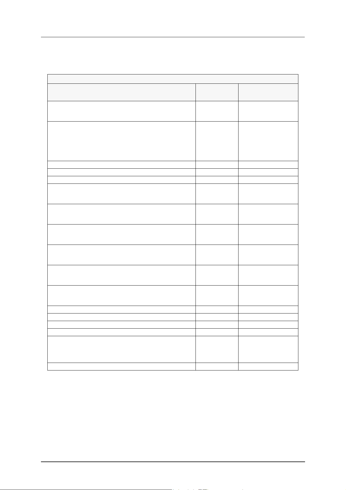
3.2.1 REFERENCE VALUES
The table shows the normal factory settings.
Reference values. Authorisation levels S1 and S2
Text in display (1) Reference
Comment
value
(1) TEMPERATURE TANK 58°C
(2) GRANULE WASHTIME P1 3.2 minutes
(3) GRANULE WASHTIME P2 6.2 minutes
(4) GRANULE WASHTIME P3 9.0 minutes
(5) CHEMICAL WASHTIME P1 1.0 minutes
(6) CHEMICAL WASHTIME P2 1.0 minutes
(7) CHEMICAL WASHTIME P3 1.0 minutes
(8) CHEMICAL WASHTIME P4 1.5 minutes
(9) CHEMICAL WASHTIME P5 3.0 minutes
(10) CHEMICAL WASHTIME P6 6.0 minutes
(12) TEMP BOILER FINAL RINSE P1/P4 85°C
(13) TEMP BOILER FINAL RINSE P2/P5 85°C
(14) TEMP BOILER FINAL RINSE P3/P6 85°C
(15) AMOUNT OF WATER FOR FINALRINSE P1/P4 5 litres
(16) AMOUNT OF WATER FOR FINALRINSE P2/P5 5 litres
(17) AMOUNT OF WATER FOR FINALRINSE P3/P6 5 litres
(18) TIME FOR SPIN DRY P1/P4 20 seconds
(19) TIME FOR SPIN DRY P2/P5 20 seconds
(20) TIME FOR SPIN DRY P3/P6 20 seconds
(23) FREQUENCY DURING WASHING 15 Hz
(24) FREQUENCY DURING SPIN DRY AFTER WASH 100 Hz
(25) FREQUENCY DURING FINAL RINSE 15 Hz
(26) FREQUENCY DURING SPIN DRY AFTER FINAL RINSE 100 Hz
(27) ACTIVATION TIME FOR DRAINING PUMP 0.0 minutes Option
(31) TIMEOUT WHEN FILLING 30 minutes
(32) TIMEOUT DURING HEATING OF TANK 15 minutes
(33) TIMEOUT DURING FINAL RINSE 30 seconds
(34) DURATION TIME FOR DETERGENT MIXING 30 seconds
(35) DURATION TIME FOR OPEN COOLING VALVE 45 seconds
(39) ALARM WHEN LOW TEMPERATURE IN TANK 45°C
(40) ALARM WHEN LOW FLOW DURING FINALRINSE 4 litres/min.
(41) MACHINE LOCKED WHEN LOW FLOW DURING FINAL RINSE YES NO No Option
(42) NUMBER OF WASHES BEFORE WATER CHANGE ALARM 25 washes Option
(43) MACHINE LOCKED WHEN WATER CHANGE ALARM YES NO No Option
(44) NUMBER OF WASHES BEFORE CONTROL OFGRANULE LEVEL 200 washes
(45) DURATION TIME FOR OUTPUT OF ALARM H20 60 seconds
(47) CONFIGURED CARD YES NO Yes
(48) FILLED BOILER YES NO No
(49) PERFORMED MAINTENANCE SERVICE YES NO No
(50) BRIGHTNESS 100
(51) CONTRAST 85
(52) LANGUAGE 0 0=Swedish, 1=English
2=German, 3=French,
4=Italian, 5=Dutch,
6=Danish, 7=Finnish,
8=Spanish
16
WD-90GR Rev. 2.0 (20110515)
Adjustment instructions
A computer must be connected to the machine for people with authorisation level
S2 to be able to change the following reference values. You connect to the machine's website and log in with a password to use WEB Tool to change the values.
Reference values. Authorisation level S2
Text in display (1) Reference
Comment
value
(101-S2) MACHINE TYPE 0 The machine must be
restarted for this to
take effect.
(105-S2) EXPO MODE NO, YES, NO WATER, YES WITH
WATER
(106-S2) CONNECTED TO POWER GUARD YES NO No Option
(108-S2) USE TIMER START YES NO No Option
(115-S2) HACCP ALARMS YES NO No Option
(116-S2) STOP IF LOW TEMPERATURE IN TANK YES NO No Option. Accessible
(117-S2) STOP IF LOW TEMP FINAL RINSE YES NO No Option. Accessible
(118-S2) STOP IF ALARM FOR OVERLOAD PUMPS YES NONo Option. Accessible
(119-S2) STOP IF DETERGENT ALARM YES NO No Option. Accessible
(120-S2) FLOW SENSOR BV02 PULSES 70 pulses The machine must be
(121-S2) FLOW SENSOR BV05 PULSES 0 pulses Option. The machine
(123-S2) ADDED OFFSET FOR TANK NAFEM 0°C Option
(124-S2) SUBTRACTED OFFSET FOR TANK NAFEM 0°C Option
(125-S2) ADDED OFFSET FOR BOILER NAFEM 0°C Option
(126-S2) SUBTRACTED OFFSET FOR BOILER NAFEM 0°C Option
(130-S2) ALARM FOR MAINTENANCE SERVICE ENABLED
YES NO
(170-S2) POWER METER PULSES 10 Option
No Option. 0=No, 1=Yes
without water & without
rotation, 2=Yes without
water & with rotation,
3=Yes with water &
with rotation
only if HACCP alarm is
selected.
only if HACCP alarm is
selected.
only if HACCP alarm is
selected.
only if HACCP alarm is
selected.
restarted for this to
take effect.
must be restarted for
this to take effect.
No Option. Alarm for main-
tenance service after
15000 dishes or ones a
year.
17

WD-90GR Rev. 2.0 (20110515)
Adjustment instructions
3.2.2 Other information from the diagnostics system
In addition to the setting options for reference values, the diagnostics system can
display other information. It is also possible to check the operation of the various
components of the machine.
In addition to the SETPOINTS group, there are also the following groups DIAGNOSIS – RELAY TEST - STATISTICS - TIME & DATE - LANGUAGE - OTHER.
3.2.3 DIAGNOSIS
In this group, the current tank temperatures, flows, water levels, information about
the motor safety cut-out for the pumps etc. are shown
3.2.4 RELAY TEST
Here, it is possible to check the operation of the various components of the machine. Scroll through until the relevant text appears on the display.
For example: RE01 CARD1 M1 CHEMICAL WASH PUMP (+) ON (-) OFF appears
on the display. Close the doors. Press the plus button (9) on the circuit board to
check the operation of the pump. Stop the pump using the minus button (9).
The door must be closed. In this mode the pumps function even when the doors
are open.
3.2.5 STATISTICS
The STATISTICS group shows the total number of washes since the machine
was first started and the highest and lowest water flows during filling and final
rinse.
3.2.6 TIME & DATE
• When the diagnostics function has been activated with button (3), select
• Press button (4). The date and time are displayed and the year flashes.
• Press button (3) to increase the value and button (4) to decrease it.
• To move to the month, press and hold button (4) until the month flashes.
• Press and hold button (4) to move to the day and time. Change them as
• Exit the diagnostics function by pressing and holding button (3).
the TIME & DATE group by pressing the same button.
Change the month in the same way using buttons (3) and (4)
necessary.
18

Adjustment instructions
3.2.7 LANGUAGE
• When the diagnostics function has been activated with button (3), select
the LANGUAGE group by pressing the same button.
• Press button (4) to display the language options.
• Choose the language by pressing the plus and minus buttons (9) on the circuit board.
• When you have chosen the language you want, press button (4).
• Exit the diagnostics function by pressing and holding button (3).
3.2.8 OTHER
The messages and functions which do not belong in any of the other groups have
been included in the OTHER group. The content of the group varies depending
on the type of machine.
3.2.9 Resetting the filling memory
WD-90GR Rev. 2.0 (20110515)
If the booster heater is emptied of water, the filling memory must be reset.
• When the diagnostics function has been activated with button (3), select
the SETPOINTS group by pressing the same button.
• Press button (4) to display the first message.
• Scroll down using button (4) until the text FILLED BOILER YES NO appears on the display.
• Choose NO by pressing the plus or minus buttons (9).
• Exit the diagnostics function by pressing and holding button (3).
• The next time the machine fills, a message indicating that the booster heater has been filled will appear automatically.
19

WD-90GR Rev. 2.0 (20110515)
Adjustment instructions
3.3 Setting up the frequency converter
1
2
3
4
Enter
5
90_16
Frequency converter
1. Display
2. Memory module
3. Button for switching between codes and adjusting values
4. Button for switching between codes and adjusting values
5. Enter button
20

WD-90GR Rev. 2.0 (20110515)
Adjustment instructions
3.3.1 Checking and setting the reference values
• When checking and setting the reference values for the frequency converter, the FU/M circuit breakers for the operating voltage and FU16 for the
drive motor must be switched on.
• Switch on the power by pressing button 0/1 on the control panel. The message STP appears on the frequency converter display (1).
• Press ENTER. A code appears on the display. Press button (3) or (4) to select the code in accordance with Table 1.
• Press ENTER to show the current value.
• Increase or decrease the value by pressing buttons (3) and (4). To change
the value quickly, press and hold the button.
• Press ENTER to save the value. The current code is shown on the display.
• The message STP will appear approximately 40 seconds after you have
checked and adjusted the values.
Table 1 – Setting up the frequency converter
Code Relates to Value
C01 Control option 3
C11 Max. frequency 150 Hz
C12 Acceleration time 6 seconds
C13 Retardation time 6 seconds
C36 DC brake 4 %
h46 Monitoring period between monitoring messages 2000 ms
h47 Consequence of timeout of monitoring period 2
h50 CAN address 2
h51 CAN data speed 4
h52 Automatic restart after power fault 1
h56 Monitoring period for communication error 1000 ms
h84 Time between status messages 500 ms
21

WD-90GR Rev. 2.0 (20110515)
Adjustment instructions
3.3.2 Alarm codes frequency converter
Alarm Cause Action
cF / CF / GF Memory failure in frequency converter. Reset the frequency converter (C02=2).Re-
move the short-circuit between 20 and 28 on
the freq. Converter. The ext "OFF" must be displayed.Note ! All values must be restored after
resetting the freq. Converter.
F1 Memory error in module. Turn off and change the memory module .
FC5 / FC3 Can communication error. Check the CAN commucation cable between
CPU and Freq.converter.
OC1 Shortcircuit or overload. Check motor and motor cable for short cir-
cuit.Check during operation that the motor is
running smoothly.Increase acceleration time
(C12).
OC2 Earth fault. Check cable to the motor for earth leak-
age.Check the wirings of the motor.
OC6 Motor overload. Check the ambient temperature for the mo-
tor.Check during operation that the motor is
running smoothly.
OH Freq.converter overheated. Check ambient temperature for the freq. Con-
verter.
dEC Intermittent overvoltage on DC-bus dur-
ing braking.If dEC is active for or then 1
second the OU-alarm will be displayed
instead.
OU Overvoltage on DC-bus during braking. Check the main power supply.Increase the val-
Increase the retardation time (C13).
ue for (C13) .Check the motor cable for damag-
es (earth leakage).
3.3.3 Changing the frequency converter
Before removing the old frequency converter, the current reference values as
shown in Table 1 must be checked and recorded.
• Use the method described in “Checking and setting the reference values”
to select the codes as shown in Table 1 and to display the current value for
each code.
• Read off the value and record it. When you have read off a value, press ENTER to return to the code display. Go on to the next code.
• When all the values shown in Table 1 have been recorded, turn off the power to the old frequency converter using the FU16 circuit breaker.
• Use needle-nose pliers to move the memory module (2) to the new frequency converter.
• Remove the old frequency converter.
• Fit the new frequency converter. Turn on the FU16 circuit breaker. Check
that the values correspond to the ones you recorded.
If a problem occurs, remove the CAN cable from the CPU board and restart the
machine. Check all the reference values and replace the CAN cable.
22
WD-90GR Rev. 2.0 (20110515)
Service
4. Service
The machine must be serviced after around 15,000 washes or once per year.
Read the SAFETY INSTRUCTIONS chapter carefully before starting work.
4.1 Repairs and machine maintenance
Switch off the power supply at the mains switch before working on the machine.
The electrical cabinet may only be opened by a qualified electrician or trained personnel.
Close all the stopcocks for incoming water and steam and reduce the pressure in
all the valves before servicing the machine. Do not start work until all the connections have been correctly shut off.
Allow the machine to cool down before starting work. The water and steam pipes,
pumps, booster heater and valves become very hot when the machine is in operation.
Use protective gloves and goggles when working on the detergent equipment.
There may be detergent in the pipes, container and other equipment.
4.1.1 Periodic maintenance
The rubber hoses on the pressure and suction side of the pumps can be affected by
hot water, vibration and detergent. The hoses must be replaced every five years.
The detergent and drying agent hoses must be replaced every two years.
4.1.2 Machine damage
The equipment must be fitted and the necessary adjustments carried out only by
authorised personnel.
To ensure that the machine can operate safely and reliably, regular, scheduled
maintenance must be carried out and the maintenance procedures must be followed carefully.
Static electricity can cause damage to sensitive equipment. Always use an
earthed static electricity wristband when handling printed circuit boards and
EPROMs.
23

Service
4.2 Drive motor
4.2.1 Assembly
The machine has a worm gear to drive the circular table.
Fitting
When fitting the worm gear, it is important that no stresses are applied to the gear
housing when it is bolted in position. Therefore you must ensure that the base of
the gear is level and stable. If the gear is incorrectly fitted, it may not function correctly and its service life can be reduced.
Fitting the disks and couplings
The wheel, disks and couplings which are fitted on the shaft journal must NOT
be fitted using hard blows. Use a rubber mallet or heat the components to a temperature of 80-100°C, depending on the tightness of the fit.
WD-90GR Rev. 2.0 (20110515)
4.2.2 Service
In the case of gears with a hollow shaft (shaft-mounted gears), it is important that
the force needed to fit them is applied to the shaft and not to the gear housing.
Electric motor
Check carefully that the motor voltage is correct.
Lubricants
Before starting the machine, check that the gear is lubricated and, if a bleed screw
is used, that it is at the top of the gear housing.
Running in
Ensure that you “run in” the motor carefully. It should only be subjected to a 50%
load initially. This should gradually be increased to 100% when it has been run in
for an hour.
The gear is supplied filled with oil. This should not need to be replaced during normal operation. If it needs to be filled with oil for some reason, different types of
oils must on no account be mixed together.
24

Troubleshooting
5. Troubleshooting
5.1 General information
The electrical cabinet may only be opened by a qualified electrician or trained personnel.
NOTE: Read the SAFETY INSTRUCTIONS before attempting any form of troubleshooting and repair work.
All work involving the dismantling of equipment must be carried out by authorised
service personnel.
WD-90GR Rev. 2.0 (20110515)
The tables describe a number of common faults, together with the components
and functions which should be checked.
In addition to the faults described in the tables, other kinds of problems could also
affect the functioning of the machine. The authorised service engineers should
therefore be familiar with the machine and use the relevant flowcharts and wiring
diagrams when troubleshooting.
To check the functioning of the different components, use the functions in the machine's software. Various values can be checked and set using the software from
the machine’s control panel. This is described in ADJUSTMENT INSTRUCTIONS.
25

WD-90GR Rev. 2.0 (20110515)
Troubleshooting
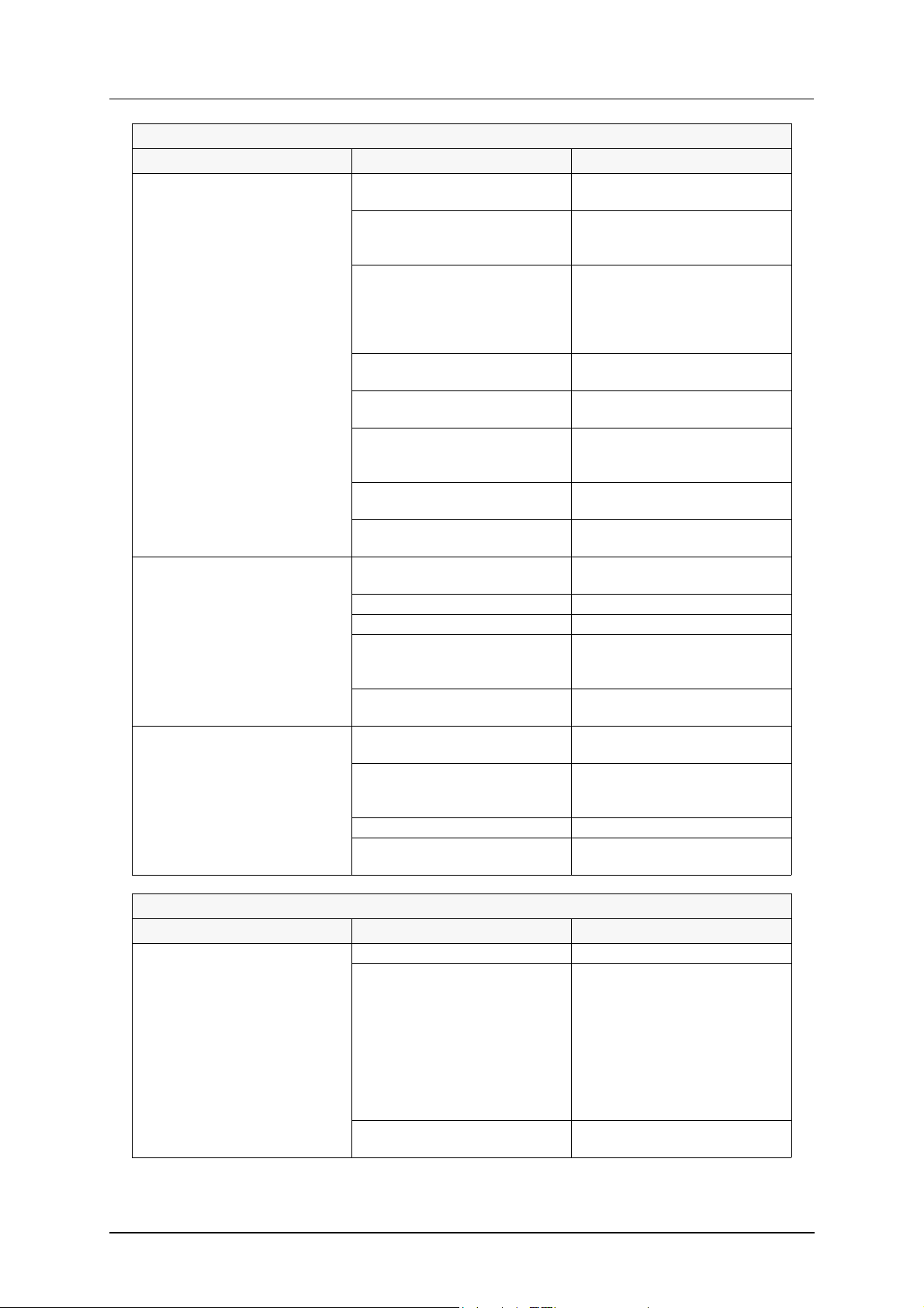
5.2 Troubleshooting
STARTING THE MACHINE
PROBLEM CAUSE ACTION
No indication on the control panel display when the control button is pressed.
FILLING
PROBLEM CAUSE ACTION
The machine does not fill with
water.
The tanks overfill. The solenoid is dirty. Clean the solenoid.
The machine fills slowly. The filter in the incoming water
No power supply to the machine. Check the fuses and the incom-
ing power cable.
The mains switch is off. Turn on the mains switch.
The circuit breaker has tripped. Reset the circuit breaker.
The stopcock on the incoming
water supply is closed.
The doors are open. Close the doors.
The solenoid switch for one of
the doors is not functioning.
The solenoid coil is defective. Replace the coil.
Fault in the level sensor. Check and, if necessary, replace
The solenoid membrane is broken.
Fault in the level sensor. Check and, if necessary, replace
The level pipe is not in place. Fit the level pipe.
The level pipe's rubber sleeve is
not sealing against the bottom
plate.
supply pipe is blocked.
The incoming water pressure is
too low.
The solenoid for the tanks is de-
fective. The solenoid is dirty.
Open the stopcock.
Check the solenoid switch.
the level sensor.
Replace the solenoid.
the level sensor.
Check that the level pipe is
closed. Change the rubber
sleeve if it is damaged.
Clean the filter.
Check the water pressure.
Check and, if necessary, clean
the solenoid. Replace damaged
parts or the entire valve.
26

WD-90GR Rev. 2.0 (20110515)
Troubleshooting
TEMPERATURES
PROBLEM CAUSE ACTION
The tank temperature is too low. The heating element in the tank
is defective. (Electrically-heated
machine).
The relay is not working. (Electrically-heated machine).
The circuit breaker has tripped.
(Electrically-heated machine).
Incorrect reference value. Check and adjust the reference
The filter in the incoming steam
pipe is blocked. (Steam-heated
machine).
The steam valve on the tank is
defective. (Steam-heated machine).
The steam pressure is too low.
(Steam-heated machine).
The steam trap is defective.
(Steam-heated machine).
The final rinse temperature
is too low.
The element in one of the booster heaters is defective. (Electrically-heated machine).
The relay is not working. (Electrically-heated machine).
The circuit breaker has tripped.
(Electrically-heated machine).
Incorrect reference value. Check and adjust the reference
The filter in the incoming steam
pipe is blocked. (Steam-heated
machine).
The steam valve on the booster
heaters is defective. (Steamheated machine).
The steam pressure is too low.
(Steam-heated machine).
The steam trap is defective.
(Steam-heated machine).
Replace the element.
Check and, if necessary, replace
the relay.
Check the power supply and re-
set the circuit breaker.
value.
Clean the filter.
Check and, if necessary, clean
the steam valve. Replace dam-
aged parts or the entire valve.
Check the steam pressure.
Check the operation of the steam
trap. Replace the steam trap if
necessary.
27

WD-90GR Rev. 2.0 (20110515)
Troubleshooting
STARTING THE WASH PROGRAMME, WASHING
PROBLEM CAUSE ACTION
The machine does not start
washing.
One of the pumps will not start. The water level in the tanks is too
The motor safety cut-out has
tripped.
Noise from the wash pump. Incorrect direction of rotation. Check that the direction of rota-
Final rinse with fresh water does
not start/stop.
The doors are not closed. Close the doors.
One of the doors’ solenoid
switches is not working.
The motor safety cut-out has
tripped.
The drive motor has burnt out. Replace the drive motor.
The relay is not working. Check and, if necessary, replace
low.
Fault in the sensor. Check and, if necessary, replace
The motor safety cut-out has
tripped.
The pump motor has burnt out. Replace the pump.
The relay is not working. Check and, if necessary, replace
The motor safety cut-out is incorrectly set.
Fault in the motor. Check the motor power supply.
Phase drop-off. Check the incoming power sup-
The motor safety cut-out has
failed.
Dirt in the pump housing. Dismantle and clean the pump
Bearing fault. Replace the bearing and the en-
Low water level. Foam in the
tank.
The solenoid is not functioning. Check the membrane and the
Check and, if necessary, replace
the solenoid switch.
See “The motor safety cut-out
has tripped”.
the relay.
Check that the level pipe's rub-
ber sleeve forms a seal against
the bottom plate.
the level sensor.
See “The motor safety cut-out
has tripped”.
the relay.
Check and set the correct value.
ply.
Replace the motor safety cut-
out.
tion matches the arrow on the
pump. Replace two of the incom-
ing phases.
housing.
tire pump, if necessary.
Check the level. Change the wa-
ter.
coil. Replace the solenoid, if nec-
essary.
28
WD-90GR Rev. 2.0 (20110515)
Troubleshooting
WASHING RESULTS
PROBLEM CAUSE ACTION
The machine is not cleaning
properly.
Granulate sticks to the washed
items.
The granulate is in the wrong
tank.
The rinsing and washing nozzles
are clogged with dirt.
There is too little detergent. Check that there is sufficient de-
The wash or rinse temperature is
too low.
The wrong wash programme. Choose a programme with a
The water in the tanks is too
dirty.
Foam is forming in the tanks. Check that the wash tempera-
One of the pumps is not working. Check the pump, motor safety
There is too little granulate in the
tank.
The wash pump is not functioning.
The granulate valve is broken. Replace the valve.
The rinse nozzles are blocked. Clean the nozzles.
There is too much foam in the
machine.
The washing time is too short. Adjust the reference value for the
The wrong type of granulate is
being used.
There is too much foam in the
machine.
The wash water is too dirty. Change the water.
The wash pump is not function-
ing.
Check and clean the nozzles.
tergent and that the detergent
dosage is correctly set.
Check: The operation of the ele-
ments in the tanks and booster
heater. Relays and circuit break-
ers. Setting of the reference val-
ues.
longer washing time.
Change the water.
ture is not too low and that the
correct detergent is being used.
cut-out and relay.
Check the amount of granulate
and add more if necessary.
Check the functioning of the
wash pump.
Check the temperatures, deter-
gent and cleanliness of the wash
water.
washing time without granulate.
Use only the original granulate.
Check the temperatures, deter-
gent and cleanliness of the wash
water.
Check the functioning of the
wash pump.
DRYING RESULTS
PROBLEM CAUSE ACTION
The washed items do not dry. The rinse nozzles are blocked. Check and clean the nozzles.
The final rinse temperature
is too low.
Incorrect dosage of drying agent. Check and adjust the dosage
29
Check: The function of the boost-
er heater elements. (Electrically-
heated machine). Relays and cir-
cuit breakers for the elements.
Operation of the solenoids. The
steam valves and steam traps for
the booster heaters. (Steam-
heated machine). The reference
values for the final rinse.
equipment.

WD-90GR Rev. 2.0 (20110515)
Troubleshooting
5.3 Error messages
Machine faults and user faults are indicated with messages on the display (1).
In addition to the alarms described in the INSTRUCTIONS FOR USE, there are
also the following alarms:
ALARM TEXT CAUSE ACTION
(63) POWER SUPPLY
FAILURE
CHECK THE
EMERGENCY SWITCH
(98) HARDWARE ERROR
POWER ON FUNCTION
DEFECT
CALL SERVICE
(3) NOMINAL VALUES
CORRUPTED IN MEMORY
CALL SERVICE
(99) THE MACHINE TYPE
HAS BEEN CHANGED
VERIFY THIS
(2) INPUT FAILURE ON
DIGITAL INPUTS
CALL SERVICE
(4) COMMUNICATION ERROR
BETWEEN CPU BOARD
AND I/O BOARD1
CALL SERVICE
(5) COMMUNICATION ERROR
BETWEEN CPU BOARD
AND I/O BOARD2
CALL SERVICE
(6) COMMUNICATION ERROR
BETWEEN CPU BOARD
AND EXTRA BOARD
CALL SERVICE
COMMUNICATION ERROR Check the CAN cabling between the panel
(9) OVERLOAD PUMPS
ACTIVATED
CALL SERVICE
(11) HACCP ALARM
PUMP DEFECT
MACHINE LOCKED
CALL SERVICE
(20) FREQUENCY INVERTER
ERROR
CALL SERVICE
(16) COMMUNICATION ERROR
FREQUENCY CONVERTER
CALL SERVICE
(18) OVERTEMPERATURE
FREQUENCY INVERTER
CALL SERVICE
(19) DC BUS OVERVOLTAGE
FREQUENCY INVERTER
CALL SERVICE
Reset the emergency stop
switch.
Relay 0 is not working. Switch the power to the machine off and on. If
Input with short-circuit. Check which input is causing the problem by re-
The motor safety cut-out for one
of the pumps has triggered.
Switch the power to the machine off and on.
the problem continues, replace the board.
Can be reset by a service engineer with authorisation level S2.
Can be reset by a service engineer with authorisation level S2.
moving one cable at a time.
Check that the CPU board is properly connected
to I/O board 1. If necessary, change the board.
Check the CAN cabling between I/O board 1
and I/O board 2. If necessary, change the board.
Check the CAN cabling between I/O board 1
and I/O board 2. If necessary, change the board.
board and the I/O board.
Check that there is 230V on all the phases to the
safety cut-out. Reset the safety cut-out and
check the voltage and amperage to the pumps.
OPTION
Check the reference values for the frequency
converter. Adjust the ramp-up times for C12,
C13.
Check that the CAN cabling between the frequency converter and the CPU board is correct.
Check the reference values for the frequency
converter. Adjust the ramp-up times for C12,
C13.
Check the reference values for FQ. Adjust C12,
C13.
30

WD-90GR Rev. 2.0 (20110515)
Troubleshooting
ALARM TEXT CAUSE ACTION
(31) TEMPERATURE
SENSOR ERROR
TANK B21
CALL SERVICE
(32) TEMPERATURE
SENSOR ERROR
BOILER B41
CALL SERVICE
(33) TEMPERATURE SENSOR
ERROR B42
CALL SERVICE
(34) TEMPERATURE SENSOR
ERROR B43
CALL SERVICE
(35) TEMPERATURE SENSOR
ERROR CONDENSOR B05
CALL SERVICE
(41) HACCP ALARM
HEATING OF TANK
DEFECT. MACHINE
LOCKED. CALL SERVICE
(62) HACCP ALARM
NO FLOW DURING
FINAL RINSE
MACHINE LOCKED
(39) FINAL RINSE ERROR
SENSOR ERROR
FLOW METER BV02
CALL SERVICE
(46) HACCP ALARM HEATING
OF TANK DEFECT. MACHINE
LOCKED. CALL SERVICE
(47) LOW TEMPERATURE
BEFORE FINALRINSE
EXTENDED CHEMICAL
WASH
(49) HACCP ALARM
HEATING OF BOILER
DEFECT. MACHINE
LOCKED. CALL SERVICE
(50) WASHING DETERGENT
ALARM ACTIVE
CHECK DETERGENT
DEVICE
(52) HACCP ALARM
WASHING DETERGENT
DEFECT. MACHINE
LOCKED. CALL SERVICE
(59) TIME TO CHANGE
WATER IN TANK
MACHINE LOCKED
(64) TIME FOR MAINTANANCE
CONTACT YOUR
MAINTANANCE
SUPPLIER
The temperature sensor has
registered either a failure or a
short-circuit in the sensor.
The temperature sensor has
registered either a failure or a
short-circuit in the sensor.
The temperature sensor has
registered either a failure or a
short-circuit in the sensor.
The temperature sensor has
registered either a failure or a
short-circuit in the sensor.
The temperature sensor has
registered either a failure or a
short-circuit in the sensor.
Check that the stopcocks on the
incoming water supply are open.
Check that the stopcocks on the
incoming water supply are open.
The sensor on the flow meter is
not sending any signals.
Check the temperature of the incoming water.
Check the detergent supply. Fill or replace the detergent.
Replace the sensor.
Replace the sensor.
Replace the sensor.
Replace the sensor.
Replace the sensor.
Reset the alarm by pressing button (7).
Reset the alarm by pressing button (7).
Check that the flow meter is functioning.
Change the flow meter or the sensor, if necessary.
OPTION
If possible, raise the temperature of the incoming water.
OPTION
OPTION
OPTION
OPTION
31
 Loading...