


GAS GRIDDLE
OFTG 40B
OFTG 40BLC
OFTG 60B
OFTG 60BLC
Installation and Operation Manual

10/31 Gas heated Fry-Tops and sloped Grillplates (FTG/BIG)
GB
INDEX
INSTALLATION INSTRUCTIONS -----------------------------------------------------------------------page ---11
WARNINGS ---------------------------------------------------------------------------------------------------------- page --- 11
INSTALLATION ------------------------------------------------------------------------------------------------------page ---11
Positioning
Assembly
In line union of the 600
Connection to gas piping
CONVERSION TO ANOTHER TYPE OF GAS ------------------------------------------------------------------------ page --- 11
Replacement of burner nozzle
Burner primary air adjustment
Replacement of minimum adjustment screw
Replacement of pilot burner nozzle
Replacement of gas preset adhesive label
START-UP ------------------------------------------------------------------------------------------------------------page --- 11
Function check
Nominal heat input check
Inlet pressure check
ANALYSIS OF SEVERAL FAILURES ---------------------------------------------------------------------------------page --- 11
Difficult or lacking pilot ignition
Extinction of pilot burner flame during operation
Extinction of main burner flame during operation
Difficult or lacking burner ignition
Difficult or lacking temperature adjustment
REPLACEMENT OF PARTS SUBJECT TO CHANGE -----------------------------------------------------------------page --- 12
Burner, Pilotburner, Thermocouple, Ignition spark plug, Safety thermostat
Gas valve, Piezoelectric igniter
USE AND MAINTENANCE ----------------------------------------------------------------------------------page ---12
WARNINGS -----------------------------------------------------------------------------------------------------------page --- 12
Additional safety device
USE ------------------------------------------------------------------------------------------------------------------ page --- 12
Burner ignition on appliances with firm splashguard
Burner ignition on appliances with removable splashguard
Burner extinction
CLEANING AND MAINTENANCE ------------------------------------------------------------------------------------page ---13
LIST OF PARTS SUBJECT TO CHANGE -----------------------------------------------------------------------------page --- 13

Gas heated Fry-Tops and sloped Grillplates (FTG/BIG) 11/31
– Screw down fixing screws and seal them with
red paint.
Replacement of gas cock minimum adjustment
screw (Fig. 1-2)
– Remove control panel of appliance.
– Unscrew the minimum adjustment screw and
replace it with the proper one indicated Table T1.
Replacement of pilot burner nozzle (Fig. 4)
– Remove control panel of appliance.
– Remove the pilot burner support plate SP, loosen
the two screws fastening the plate at the front.
– Unscrew pipe fitting R and replace nozzle B with
the proper one indicated in Table T1.
– Screw down pipe fitting R.
Replacement of gas preset adhesive label
– Apply the correct adhesive label which indicates
the new type of gas for which the appliance is
now set.
START-UP
Function check
– Start-up the appliance according to instructions
for use and check the regularity of the burner
ignition, the absence of gas leaks and the efficiency
of the burnt gas exhaust system.
– If necessary consult paragraph “Analysis of
several failures”.
Nominal heat input check
– After installation or adjustment to another type
of gas and at each maintenance intervention
check the heat input of the appliance.
– The nominal heat input is stated in the “Technical
data” table.
– The appliance operates at the nominal heat
input when the nozzles assembled are suitable
for the type of gas used and the inlet pressure is
the one indicated in Table T1.
– For the measurement of the inlet pressure read
paragrah “Inlet pressure check”.
Inlet pressure check
– For the measurement of the inlet pressure use a
gauge having a minimum definition of 0.2 mbar.
– Remove front panel of appliance, remove seal
screw C from upstream pressure tapping and
connect the gauge pipe.
– Carry out the measurement with appliance on.
– If the value is not within the limits indicated in
Table T3, interrupt the operation of the appliance
and contact the gas delivery body.
– Disconnect the gauge pipe and screw down seal
screw C.
ANALYSIS OF SEVERAL FAILURES
Difficult or lacking pilot ignition
– Insufficient gas inlet pressure.
– Obstructed nozzle or main.
– Defective gas cock.
INSTALLATION INSTRUCTIONS
WARNINGS
Installation, adjustments and maintenance of the
appliances must be done by authorized installers,
in accordance with the safety standards in force.
The manufacturer declines any responsibility
if such obligation is not observed.
INSTALLATION
Positioning
– The overall/connection dimensions and the tech-
nical data are stated in the pages in the appendix.
– Install the appliances only in sufficiently aired
rooms.
– Fry-tops are type “A” appliances and for this
reason the rooms must be ventilated in
accordance with the technical standards in force.
– Position appliances at least 10 cm from the
nearby walls. Such distance can be less when
the walls are incombustible or protected by a
thermal insulator.
– The appliances are not suitable for built-in
installation.
Assembly
– Remove the film which protects the external
panels. Any glue remaining on these is to be
removed with a suitable solvent.
In line union of the 600 series appliances
– Put the appliances next to eachother and level
them at the same height.
– Unite the appliances using the special union
joint-coverings supplied upon request.
Connection to the gas piping
– Before carrying out the connection consult the
gas delivery body.
– Install a fast-closing cut-off cock upstream from
the appliance in an easily accessible place.
– Check if the appliance is set for the type of gas
with which it will be fed. If it is not, read
paragraph “Adaptation to another type of gas”.
– Check for any leaks in the connection points.
CONVERSION TO ANOTHER TYPE OF GAS
To adapt appliances to work with other tyes of gas
carry out all the operations stated below.
Nozzles, minimum adjustment screws and adhesive
labels are in the bag supplied with the appliance.
Replacement of burner nozzles (Fig. 3)
– Remove front panel of appliance.
– Remove the nozzle-support manifold RU.
– Unscrew nozzles and change them with the
proper ones according to Table T1.
Burner primary air adjustment (Fig. 3)
– Remove front panel of appliance.
– Operating on the shutters adjust primary air inlet
at the distance “A” indicated on Table T1.

12/31 Gas heated Fry-Tops and sloped Grillplates (FTG/BIG)
– Defective piezoelectric igniter, ignition spark
plug or cable.
Extinction of pilot burner flame during operation
– Gas inlet pressure drop
– Defective or insufficiently heated thermocouple,
or poorly connected to the gas cock.
– Defective gas cock.
– Defective or intervention of safety thermostat
(models with chromed plate).
Extinction of main burner flame during operation
– Gas inlet pressure drop
– Defective or insufficiently heated thermocouple,
or poorly connected to the gas cock.
– Defective gas cock.
– Defective or intervention of safety thermostat
(models with chromed plate).
Difficult or lacking burner ignition
– Insufficinet gas inlet pressure.
– Obstructed nozzle.
– Defective or intervention of safety thermostat
(models with chromed plate).
– Defective gas cock.
Difficult or lacking temperature adjustment
– Defective gas cock.
REPLACEMENT OF PARTS SUBJECT TO CHANGE
Sealed components must not be tampered
with.
After each intervention, if necessary, check
for the absence of gas leaks.
Burner, Pilotburner, Thermocouple, Ignition spark
plug, Safety thermostat
– Remove control panel of appliance and replace
the component.
Gas cock, Piezoelectric igniter
– Remove control panel of appliance and replace
the component.
USE AND MAINTENANCE
WARNINGS
The appliance is for professional use and must be
used by trained personnel. The appliance has to be
used only for direct cooking of food, laying the food
to be cooked (meat, hamburger, fish, vegetables,
etc.) directly on the hot surface of the plate. Any
other use of the appliance is considered improper.
It is absolutely forbidden to use the plate for
indirect cooking of food, laying pots casseroles
or pans containing food on the plate.
The installation and adaptation to other types of gas
must be done by qualified and authorized installers.
In case of breakdown close the gas cut-off cock
upstream from the appliance.
Sealed components must not be tampered with.
For repairs consult only authorized service centres
and ask for original spare parts only.
The manufacturer declines any responsability
if such obligations are not observed.
Carefully read this booklet and keep it in a safe place.
Before using the appliance carefully clean all the
surfaces that will come in contact with food.
Additional safety device
Appliances with chromed plate are provided with
an additional safety thermostat which operates
shutting off the outflow of gas when, for any
failure, the cooking plate exceeds maximum temperature allowed. If this event occurs close the gas
cut-off cock and call for a authorized technician.
USE
Burner ignition on appliances with firm splashguard
(Mod. BIG-40/60)
The gas cock knob has following references
● off
pilotburner
maximum flame
minimum flame
– Push down the knob and turn it to position .
– Maintain the knob pushed down and operate on
piezoelectric igniter push-button to light the
flame. Hold knob in for about 20 seconds then
release it and check that the flame stays alight
(if the pilot flame turns off repeat the operation).
– Turn the knob to the desired cooking tempera-
ture.
– The burner flame can be seen through the peep
hole on the front panel.
Burner ignition on appliances with removable
splashguard and appliances with chromed plate
(Mod. FTG-40B/60B/60BR/80B/80BR/40BLC/
60BLC)
The thermostatic gas cock knob has following
references
● off
pilotburner
1 Minimum temperature
2 - 6 Intermediate temperature
7 Maximum temperature
– Push down the knob and turn it to position .
– Maintain the knob pushed down and operate on
piezoelectric igniter push-button to light the

Gas heated Fry-Tops and sloped Grillplates (FTG/BIG) 13/31
flame. Hold knob in for about 20 seconds then
release it and check that the flame stays alight
(if the pilot flame turns off repeat the operation).
– Turn the knob to the desired cooking tempera-
ture.
– The burner flame can be seen through the peep
hole on the front panel.
Burner extinction
– Turn knob to position .
– To extinguish pilot burner turn it to position ●.
CLEANING AND MAINTENANCE
– Before any cleaning operation disconnect the
electrical supply (if present).
– Clean stainless steel surfaces daily with water
and non abrasive common detergents, rinse
well and dry thoroughly.
– Do not use iron scouring pads or chlorate
products.
– Do not use sharp objects which can scratch and
ruin the steel surface.
– Do not use corrosive products to clean the floor
under the appliance.
– Do not wash the appliance with water jets.
– Before a long period of inactivity close the gas
cut-off cock upstream from the appliance.
Proceed to its thorough cleaning.
– At least twice a year, ask for the intervention of
an authorized technician authorized for checking
the appliance and the cleaning of the burnt gas
discharge duct. It is advisable in any case to
stipulate a maintenance contract.
LIST OF PARTS SUBJECT TO REPLACEMENT
– Gas cock
– Thermostatic gas cock
– Main burner
– Pilot burner
– Thermocouple
– Pilot ignition spark plug
– Safety thermostat (on models with chromed
plate)


TECHNICAL DATA
T1
GAS
P
mbar
OFTG-40B.. OFTG-60B..
G20
G20+G25
20
20/25
ugelli bruciatore •
2x120 4x120
ugelli pilota ▲
4 2x4
A = mm
3 3
vite minimo**
100 100
G25
20
ugelli bruciatore •
2x135 4x135
ugelli pilota ▲
4 2x4
A = mm
3 3
vite minimo**
100 100
G25
25
ugelli bruciatore •
2x120 4x120
ugelli pilota ▲
4 2x4
A = mm
3 3
vite minimo**
100 100
G30+G31
G30 G31
29/37
29 29
ugelli bruciatore •
2x80 4x80
ugelli pilota ▲
3 2x3
A = mm
4 4
vite minimo**
70 70
G30
G3
1
50
50
ugelli bruciatore •
2x70 4x70
ugelli pilota ▲
2 2x2
A = mm
4 4
vite minimo**
70 70
G110
8
ugelli bruciatore •
2x290 4x290
ugelli pilota ▲
1 2x1
A = mm
35 35
vite minimo**
REG. • • REG. ••
G120
8
ugelli bruciatore •
2x230 4x230
ugelli pilota ▲
1 2x1
A = mm
35 35
vite minimo**
REG. • • REG. ••
G20
25
ugelli bruciatore •
2x115 4x115
ugelli pilota ▲
4 2x4
A = mm
3 3
vite minimo**
100 100
G25.1
25
ugelli bruciatore •
2x130 4x130
ugelli pilota ▲
4 2x4
A = mm
3 3
vite minimo**
100 100
• Burner nozzle
▲ Pilot burner nozzle
** Minimum adjusting screw
• • Adjustable

29/37
20
20/25
29/37
29
29
20
8
20
8
20
50
50
25
50
50
20
20
29
29
29
29
20
8
8
29
29
25
30
30
25
50
50
20
28-30/37
G30+G31
G20
G20+G25
G30+G31
G30
G31
G20
G110
G20
G110
G20+G25
G30
G31
G25
G30
G31
G20
G20
G30
G31
G30
G31
G20
G110
G120
G30
G31
G20/G25.1
G30
G31
G20/G25.1
G30
G31
G20
G30+G31
Category
II 2H 3+
II 2E+ 3+
III 1a 2H 3B/P
II 1a 2H
II 2ELL 3B/P
I 2L
II 2H 3B/P
II 2H 3B/P
III 1ab 2H 3B/P
I 3B/P
II2HS3B/P
II2HS3B/P
I2E
I3+
Country
IT GR
IE SK
PT
ES
GB
FR
BE
DK
ES IT
CH
DE
NL
AT
CH
FI BG
EE LV
SI LT
CZ
SE
NO CY
MT NL
HU
HU
LU
LU
T4
GAS P mbar
TECHNICAL DATA

T3
P mbar
G20
G25.1
G20 G25 G25 G30 G31
G30-G31 G110 G120
nom.
25 25 20 20 25
29 37
50
8
8
min 18
18 17 18
20 25 30
42,5
6
6
max 33 33 25 25 30 35
45
57,5
15 15
T5
OFTG-40B.. OFTG-60B. .
MAX. MIN. MAX. MIN.
G20 25 mbar k W
5 1,75 10 3,5
G25.1 25 mbar k W
5 1,5 10 3
Qn kW
G20
20 mbar kW
5 1,75 10 3,5
G25 (NL) 25 mbar kW 4,75
1,75 9,5 3,5
G25 (DE) 20 mbar kW
5 1,5 10 3
G30 29 mbar k W
5 1,9 10 3,8
G30 50 mbar k W
5 2,3 10 4,6
G110 8 mbar k W
5 2,1 10 4,2
G120 8 mbar k W
5 2,3 10 4,6
G20 2 5 mbar m3/h 0,5 3
0,18
1,06 0,37
G25.1 25 mbar m3/h 0,61
0,18
1,23 0,37
Kaasun
G20
20 mbar m3/h
0,53
0,18
1,06 0,37
kulutus G2 5 (NL) 25 mbar m3/h 0,58
0,22
1,17 0,43
G25 (DE) 20 mbar m3/h 0,62
0,18
1,23 0,37
G30 29 mbar k g/h 0,39
0,15
0,79 0,30
G30 50 mbar k g/h 0,39
0,18
0,79 0,36
G110 8 mbar m3/h 1,29
0,54
2,58 1,08
G120 8 mbar m3/h 1,15
0,53
2,29 1,06
Gas
consumption
GAS
60
3,6 3,6
G
G
60
G
40
40
3,6 3,6
G
5,3
60
5,4
G
5,92
1142,5
6,5
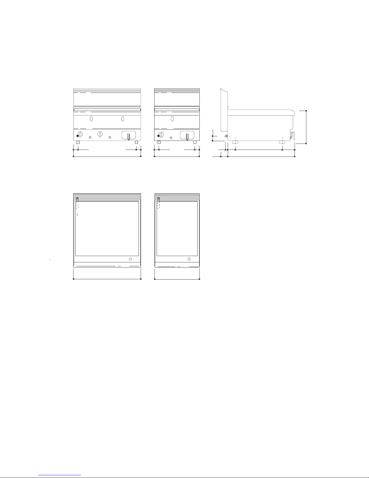
2
OFTG-40B... OFTG-60B...
ASENNUSKUVA - INSTALLATIONSBILD - INSTALLATION DIAGRAM
(Mitat cm - Mått cm - Measurements cm)
G Kaasuliitäntä - Gasanslutning - Gas connection ISO 7/1 R1/2
OFTG-60B.. OFTG-40B..
 Loading...