

Page 1
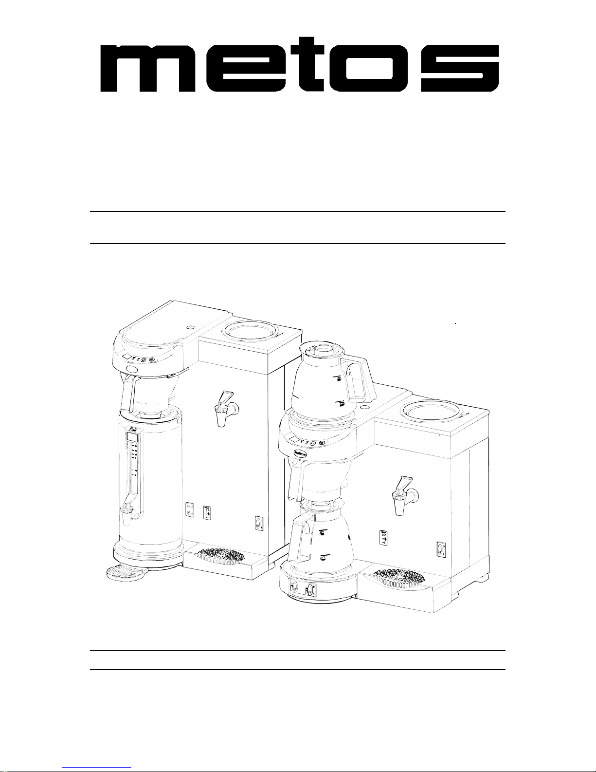
COFFEE MAKER
M-Series
TYPE: M200W, M202W, MT200W, MT202W
Installation and Operation Manual
m
e
t
o
s
m
e
t
S/N: Rev.: 2.1
Page 2

Page 3

8.5.2008 Rev. 2.1
1
Dear C us tom e r ,
Congratulatio ns on deciding to choose a Metos app liance for y our kitchen a ctivities. You
made an excellent choice. We will do our best to make you a satisfied Metos customer
like thousands of customers we have around the world.
Please read this manual carefully. You will learn correct, safe and efficien t working methods in order to get the best possibl e benefit from the applia nce. Th e instr uctions and hints
in this manual will give you a quick and easy start, and you will soon note how nice it is
to use the Metos equipment.
All rights are reserved for technical changes.
You will find the main te chnical da ta on the rating plate fixed to the equipment . When you
need service or technical help, please let us know the serial number shown on the rating
plate. This will make it easier to provide you with correct service.
For your convenienc e, spa ce is pro vide d below f or you to r ecord you r lo cal Me tos s ervic e
contact informati on.
METOS TEAM
Metos service phone number:...............................................................................................
Contact person:....................................................................................................................
Page 4

8.5.2008 Rev. 2.1
2
Page 5

8.5.2008 Rev.
1
1. General ...... .. ....................................................................................... ........... 1
1.1 Symb o l s us e d i n th e manual ...... ........ .............. ............... .............. .............. .............. ..... 1
1.2 Symb o l s us e d o n the ap p liance .............. .............. ............... .............. .............. .............. . 1
1.3 Chec k i n g the relation o f t h e ap p l iance and the manual .... .............. .............. .............. ... 1
2. Safety in st ructions ............................................................... ......................... 2
2.1 General .......................................................................................................................... 2
2.1.1 In structio n s for use ............... .................... ............... .............. .............. .............. ..... 2
2.1.2 Installation ............................................................................................................. 2
2.1.3 Usage ..................................................................................................................... 2
2.1.4 Maintenance and troubleshooting .......................................................................... 3
2.2 Safeg u a rd s .......... ........................................................................................................... 3
2.2.1 Dry-boil protection (14) ......................................................................................... 3
2.2.2 On/off switch (1+13) ............................................................................................. 3
2.2.3 Sta r t/stop b u t ton (5.5) ................ .................... ............... .............. .............. ............. 4
2.2.4 Ju g de t e c t o r ( 1 0 ) .................... .............. ..................... .............. .............. .............. ... 4
2.2.5 Ov e rf low safeg u ard .... ........ .............. .............. ............... .............. .............. ............. 4
2.3 Appliances and the environment ................................................................................... 4
2.3.1 Th e p a ck ing mate ri al ............... .............. ............... .............. .............. .............. ....... 4
2.3.2 Discardin g the a p p l i a n ce .... .............. .............. ............... .............. .............. ............. 4
3. Functional description .................................................................................. 5
3.1 Use of the appliance ...................................................................................................... 5
3.1.1 Other use .............. .............. .............. .............. ............... .................... .............. ...... . 5
3.2 Construction .................................................................................................................. 6
3.3 Control panel of the coffee making section ................................................................... 7
3.3.1 Display (5.1) ........ .............. .............. .............. ..................... .............. .............. ....... 8
3.3.2 De sc ale indic at ion light (5 .2) ..... .............. ............... .................... .............. ............. 8
3.3.3 Br e w i n g pr o ce ss indica t o r l ight (5.3) ................. .............. .............. .............. ......... 8
3.3.4 Sound signals ......................................................................................................... 9
3.3.5 Selection button (5.4) ............................................................................................. 9
3.3.6 Sta r t/stop b u t ton (5.5) ................ .................... ............... .............. .............. ............. 9
3.4 Indi c a t o r p an e l o f t h e water boiler ......... .............. ............... .............. .............. .............. . 9
3.4.1 Refill indi c a t o r light (12.1 ) ........ ........ ..................... .............. .............. .............. ..... 9
3.4.2 Temperature ok indicator light (12.2) .................................................................. 10
3.4.3 Tem p e rature a d juster water boile r (1 2 .3) ..................... .............. .............. ........... 10
4. Operation instructions ............................................................................... 11
4.1 First time use .................................................... ......... .. .......... .......... .......... .......... ........ 11
4.1.1 Da i l y us e .. .................... .............. .............. ............... .............. .............. .............. ... 12
4.2 Operation procedures ................................................................................................... 13
Page 6

8.5.2008 Rev.
2
4.2.1 Mak i n g c o ffee ................ .............. .............. ............... .............. .................... ......... 1 3
4.2.2 Water boiler ......................................................................................................... 13
4.2.3 Potentials of the water boiler ............................................................................... 14
4.2.4 Settings ................................................................................................................. 14
4.3 Maintenance ................................................................................................................ 17
4.3.1 Cleaning of the appliance and accessories ....... ........... .... ...... .... ...... .... ...... .... ...... . 17
4.3.2 Removing coffee deposits from glass jug and filter ............................................ 17
4.3.3 Rem o v ing coffe e d ep o sits from t hermos jug ................ .............. .............. ........... 17
4.3.4 Descaling ............................................................................................................. 18
4.3.5 Swi t c h i n g -off the des c a l e indicat o r l i g h t ....... ............... .................... .............. ..... 18
4.3.6 De sc aling the w ater boile r ....... ........ .............. ............... .............. .................... ..... 19
5. Install a ti o n .................................................. ................................................. 20
5.1 General ........................................................................................................................ 20
5.1.1 Un p a c k i n g .......... .............. .............. .............. ............... .................... .............. ....... 20
5.2 Installatio n .......... ......................................................................................................... 21
5.2.1 Preparation for positioning the appliance ............................................................ 21
5.2.2 El ec t rical co n n ec t i o n s ............ .............. ............... .............. .............. .............. ....... 21
5.2.3 Co n n ec t i o n to the water m a i n s ....... .............. ..................... .............. .............. ....... 21
5.2.4 Wa t e r dr a i n ag e ......... .............. .............. ..................... .............. .............. .............. . 21
5.2.5 Setting th e des c ale indic ator .... .............. ............... .............. .............. .............. ..... 22
5.2.6 Resetting the descale indicator light .................................................................... 22
6. Service .................................................. ........................................................ 23
7. Troublesh o oti ng .......................................................................................... 25
9. Technical specifications .............................................................................. 47
Page 7
8.5.2008 Rev. 2.1
General
1
1. General
Carefully read the instructions in this manual as they contain important information regarding proper, efficient and safe installation, use and maintenance of the appliance .
Keep this manual in a safe place for eventual use by other operators of the appliance.
The installation of this appliance must be carried out in accordance with the manufacturer’s instructions and following local regulations. The connection of the appliance to the
electric and water supply must be carried out by quali fied persons only.
Persons using this appliance should be spe cifically trained in its operation.
Switch off the appliance in the case of failure or malfunction. The periodical function
checks requested in the manua l must be carried out a ccording to the instructions . Have the
appliance serviced by a technically qualified person authorized by the manufacturer and
using original spar e part s.
Not complying with the above may put the safety of the appliance in danger.
1.1 Symbols used in the manual
This symbol in forms about a sit uation whe re a saf ety ri sk m ight be at h and. Give n i nstructions are mandatory in order to prevent injury.
This symbol informs about th e rig ht way to per form in orde r to preve nt bad resul ts, a ppliance damages or hazardous situations.
This symbol informs about recom me ndations and hints that hel p to get the best performance out of the appliance.
1.2 Symbols used on the ap pliance
This symbol on a part informs about electrical terminals behind the part. The removal of
the part must be carried out by qual ified persons only.
1.3 Checking the relation of the appliance and the manual
The rating plate of the appliance indi cates the serial num ber of the appliance. If the manuals are missing, it is possible to order new ones from the manufacturer or the local representative. When ordering new manuals it is essential to quote the serial number shown
on the rating plate.
Page 8

8.5.2008 Rev. 2.1
Safety instructions
2
2. Safety instructions
2.1 General
This appliance meets the m andat ory sa fety regulat ion s. I nexpert use can r esult in pe rsona l
injury and material damage. The following warnings and safety instructions must be observed bef o re using the coffee maker.
2.1.1 Instructions for use
Read these instructions for use carefully, before using this appliance. This will protect
your safety and prevent damage being caused to the appliance. Perform the various actions in the order given. Always keep this manual in the vicinity of the appliance.
2.1.2 Installation
• Place the appliance at buffet height and on a firm, level base, in such a way that it
can be connected to the water and power supply.
• Connect the appliance to an earthed wall socket.
• Position the appliance in such a way that no da ma ge can be caused if it leak s.
• Do not tilt the appliance, always position and move the appliance upright.
• The coffee make r is fi tte d with a n overflo w devi ce tha t dis charges at the bot tom of
the appliance - take this into account when positioning the appliance.
• Water always remains in the heating system: for this reason the appliance must not
be placed in an area where the temperature can fall below freezing point.
• When installing the appliance, always observe the local rules and use approved
materials and parts.
• The ‘Installation’ chapter must again be followed when repositioning the appliance.
• Connect the appliance to the cold water mains.
2.1.3 Usage
• Inspect the appl iance before using it and ch eck it for damage.
• Never submerge or spray the appliance.
• Do not press the buttons with a sharp object.
• Protect the cont r o ls again st dirt and grease.
• It is advisable to take the plug out of the socket and close the water tap, if the appliance will not be used for longer periods of time.
Page 9

8.5.2008 Rev. 2.1
Safety instructions
3
2.1.4 Maintenance and troubleshooting
• Observe the descaling intervals indicated by the descaling indicator light.
• Overdue maintenance to the heating system can result in high repair c osts and annulment of the guarantee.
• Always follow the manufacturer’s instruc tions when using the descali ng agent.
• Do not leave the appliance unattended when maintenance is being performed.
• When descaling the appliance, it is advisable to wear s afety glasses and protective
gloves.
• Flush th e ap p l ia nce at least tw ice after de s ca li ng it.
• Wash your hands thoroughly after descaling the appliance.
• Always have repairs carried out by a qualified servic e engi neer.
• The plug must be taken out of the socket if the appliance has to be opened for
cleaning or repairs .
The manufacturer cannot be held liable for losses caused as a result of failure to observe
these safety ins tructions.
2.2 Safeguards
The appliance is fitted with the following safeguards:
2.2.1 Dry-boil protection (14)
This application is equipped with two dry-boil protection on the back. The protector on
the left (21) is that of the water boiler. On the right (20) is the one of the coffee making
section.
These protectors trigger if the heating element overheats owing to a fault. Once the fault
has been resolved, the dry-boil protection can be reset at the back of the appliance. The
most common cause of the dry- boil prot ecti on b ein g tr iggere d is n ot d escali ng the heati ng
system in time.
If the heating system does not switch back on, proceed as follows:
• Allow the applia nce to cool down.
• Unscrew the protective cap, which can be foun d on the ba ck of the appliance.
• Press the button whic h is now visible and f irm ly screw the protective ca p back on.
If the dry-boil protec tion triggers owing to increas ed scale depo sits, descale the applian ce.
Consult your deale r if t he fault was caused by a probl em o ther t han t he dry-boil prot ecti on
being triggered.
2.2.2 On/off switch (1+13)
Each appliance is switched on/off separat ely through the on/off swit ch (1+13). Remembe r
that the appliance can st ill be live after swi tching it off! For thi s reas on you should al ways
remove the plug from the socket to render the appliance voltage-free.
Page 10

8.5.2008 Rev. 2.1
Safety instructions
4
2.2.3 Start/stop button (5.5)
The coffee making process can be interrupted at any point using the Start/stop button located on the control panel.
2.2.4 Jug detector (10)
This appliance is fitte d wit h a jug de tect or that op erate s the l eak stop unde r the fil te r. This
jug detector also ensures that the appliance only makes coffee if there is a jug under the
filter. If the jug is removed during the coffee brewing process, the process will be interrupted and the leak stop in the filter will prevent coffee dripping on the hot plate.
2.2.5 Overflow safeguard
The amount of water required is regu lated and monitored by flow and le vel sensors.
• Coffee making sec tion: If one of the two sensors detect s an irregularit y, the appliance switches off and both indicator lights will flicker.
• Water boiler : If the wa ter le vel of t he water boi ler re aches t he maximum l evel sensor, the machine will shut off and both indicator lights (12.1+12.2) will start to
flicker.
2.3 Appliances and the environment
2.3.1 The packing material
Your new coffee maker has been carefully packaged to protect it against damage.
The packing is not harmful to the environment and consists of the following materials:
• corrugated cardboard
• filler eleme nts made of polyurethane foam <PUR> cover ed with a polythene film
(>PE-HD<). The wast e pr ocess ing pla nt in you r munic ip ality wil l be pleas ed t o i nform you about where you can dispose of the materials.
2.3.2 Discarding the appliance
No appliance lasts forev er. When the time comes to discard your appliance it will usually
be possible to return it to your dealer. If this is not the case, ask your municipal council
about the alterna tives for recycling the material s. All plastic parts have been g iven standard codes. The parts of the appliance such a s the printed circ uit board and accompanying
parts form electrical and electronic waste. The metal body is made of stainless steel and
can be completely dismantled.
Page 11

8.5.2008 Rev. 2.1
Functional description
5
3. Func tional descri ption
3.1 Use of the appliance
The sole use of this appliance is to make coffee and/or tea, and to warm water.
3.1.1 Other use
The use of the appliance for other purposes is not permitted and may be hazardous. The
manufacturer cannot be held liable for losses caused by using the appliance for purposes
other than those indicated here or by incorrect use.
Page 12
8.5.2008 Rev. 2.1
Functional description
6
3.2 Construction
m
e
t
o
s
Page 13

8.5.2008 Rev. 2.1
Functional description
7
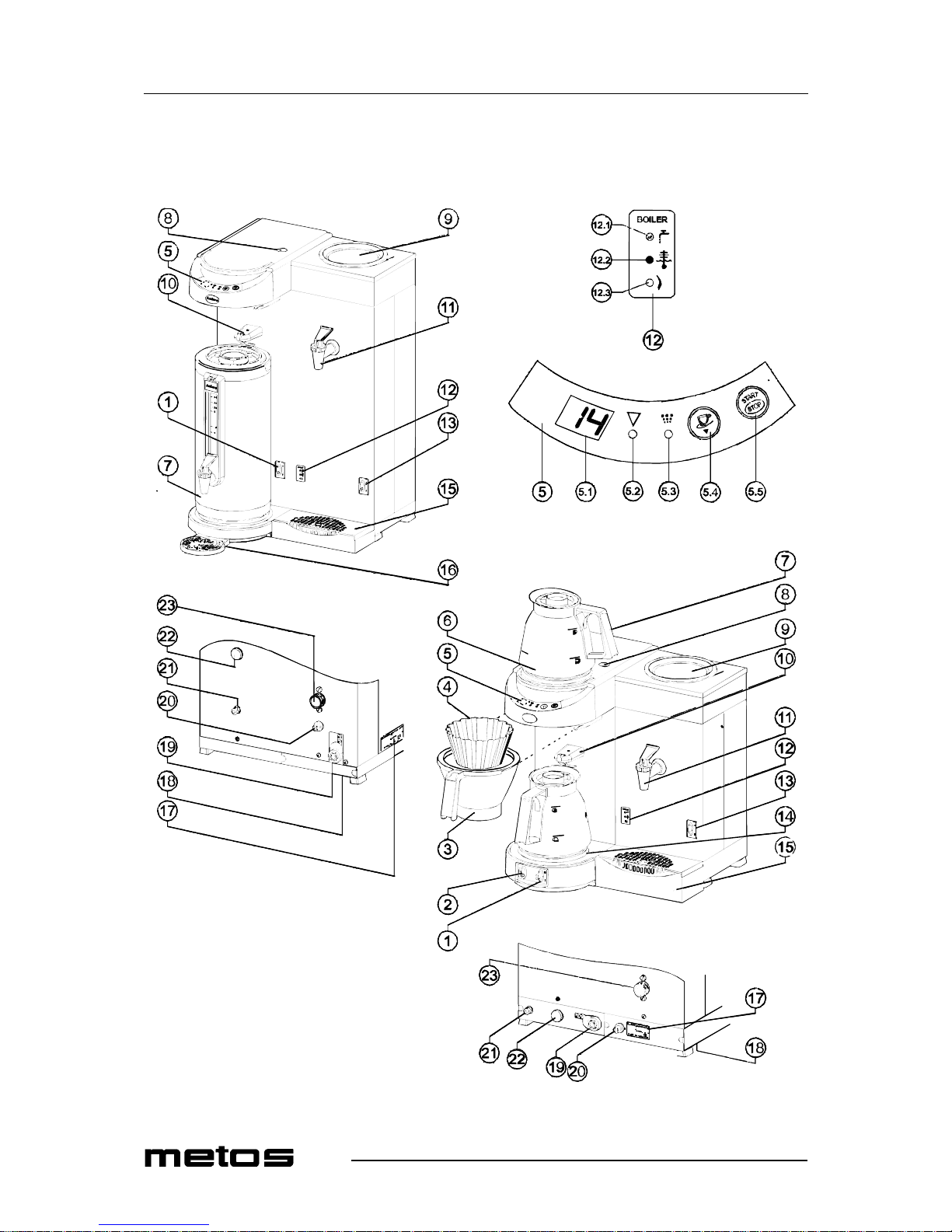
The most important parts (see pic.):
1. Appliance on/off swi tch, coffee making sect ion and bottom hot plate
2. On/off switch for top hot plate
3. Basket filte r with leak stop device
4. Basket filte r pape r
5. Control panel coffee making section (see bel ow for details)
6. Top hot plate
7. Glass jug/thermos flask
8. Descaling opening
9. Water boiler
10. Jug detector
11. Hot water ta p
12. Indicator pan el wa ter boiler (see below for details)
13. On/off switch water boiler
14. Bottom hot plate
15. Stainles s steel drip tray
16. Synthetic drip tray
17. Type plate
18. Water drain
19. Connection cable with plug
20. Dry-boil protection coffee making sect ion
21. Dry-boil protection water boiler
22. Drainage water boiler
23. Water connection
Control panel coffee making section:
•5.1 Display
• 5.2 Descale ind i cator ligh t
• 5.3 Brewing process indicator light
• 5.4 Selecti on button
• 5.5 Start/ stop button
Indicator panel water boiler:
• 12.1 Refill in dicator li g ht
• 12.2 Temperature ok indicator light
• 12.3 Temperature setting water boiler
3.3 Control panel of the coffee making section
Never press the buttons wit h a sh arp object.
Protect the control s against dirt and grease.
Page 14
8.5.2008 Rev. 2.1
Functional description
8
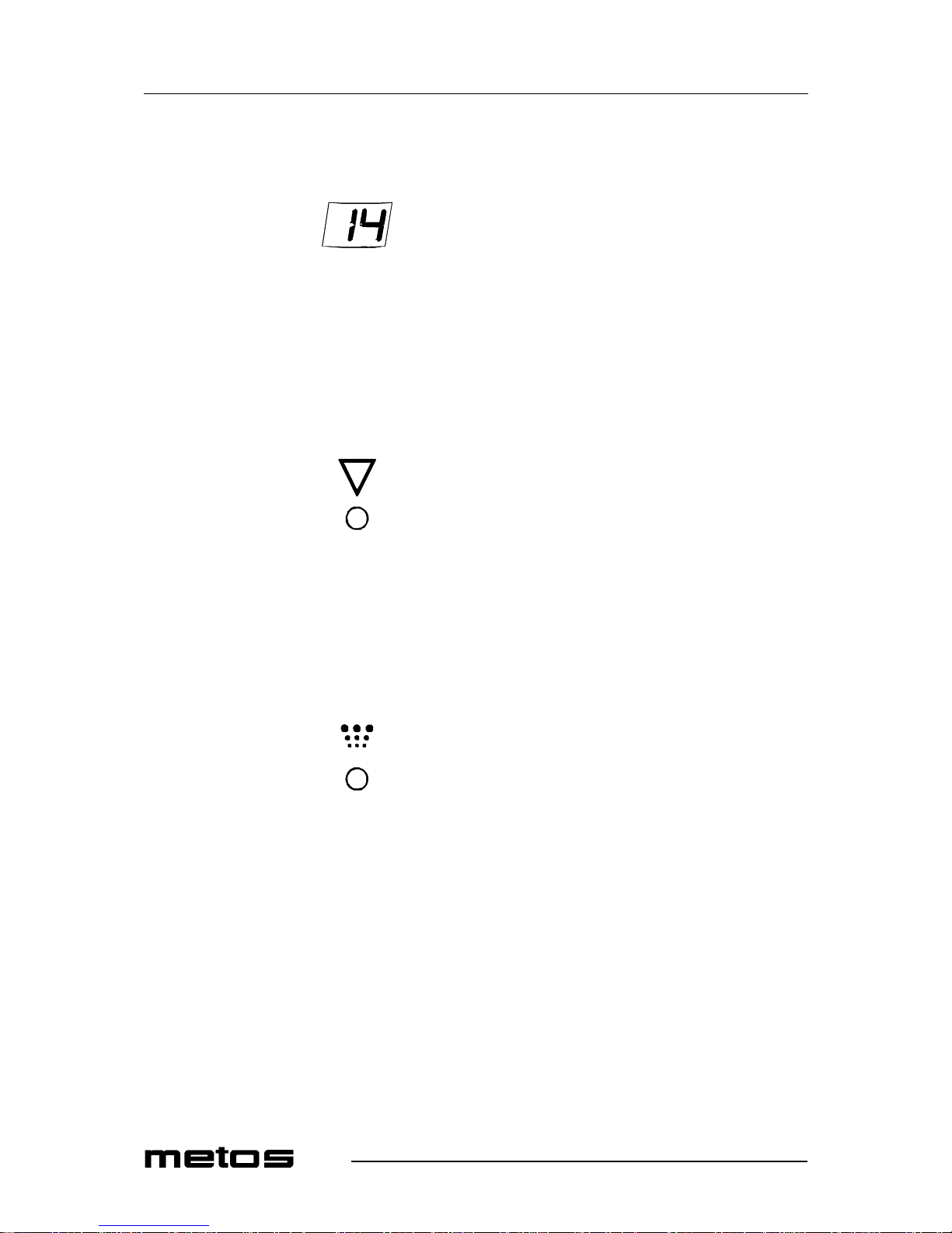
3.3.1 Display (5.1)
The display shows the selec ted amount of coffee, in terms of cups or litr es. For displa y in
litres, see Settings chapter.While the coffee is being made the display alternately shows
the selected amount and the amount of coffee that has already been made.
3.3.2 Descale indication light (5.2)
The red indicator light will light up if the appliance needs to be descaled. The appliance
will continue to work so that it can be descaled when it is not being used. See also Descaling chapter.
3.3.3 Brewing process indicator light (5.3)
The green indicator light lights up when the coff ee passes throug h the system. At the end
of the coffee maki ng process a si gnal so unds t hree ti mes a nd the g reen indi cator light g oes
out. The indicat or light fli ckers if th e jug is tem porarily remove d during t he coffee making
process. A signa l will also sound indicating that the coffee making process has temporarily stopped.
Page 15

8.5.2008 Rev. 2.1
Functional description
9
3.3.4 Sound signals
Sounds three times at the end of the coffee making process. Sounds once if the jug is removed during the coffee making process. A long signal sounds when the appliance is
switched on.
3.3.5 Selection button (5.4)
The selection button is used to reduce the amount of coffee set in the display. When the
lowest value is reached the display returns to the maximum amount.
3.3.6 Start/stop button (5.5)
The start/stop button is used to start and (emergency) stop the coffee making process.
3.4 Indicator panel of the water boiler
3.4.1 Refill indicator light (12.1)
The yellow indic ator li ght wil l ligh t up if the water boil er nee ds to be ref ill ed. The heati ng
element will turn off. The indicator light turns off w hen the water boiler has filled up sufficiently.
Page 16

8.5.2008 Rev. 2.1
Functional description
10
3.4.2 Temperature ok indicator light (12.2)
The gr een i nd i ca to r li g ht li g ht s u p w h en t he w at er bo i le r ha s re ached the correct temperature. The control light turns off when the water temperature is too low.
3.4.3 Temperature adjuster water boiler (12.3)
With this tuner the water boiler temperature can be increased/reduced, using a small
screwdriver. See chapter: Setting the water temperature of the water boile r.
Page 17
8.5.2008 Rev. 2.1
Operation instructions
11
4. Operation instructions
4.1 First tim e u se
Ensure that the mains lead does not come into contact with the hot plates (if present).
When used for the first time the appliance works according to the standard factory settings. The va rious settings can be altered by authorised personne l. See chapter ‘Settings’.
• Connect the water connection hose (supplied) to the swivel nut on the back of the
appliance and to manually-operated aeration tap. NB! Only cold water. Open the
water tap and check the co nnec tion for leaks.
• Slide an empty basket fi lter (3) into the appliance and plac e an empty jug (with lid)
underneath it.
• Check if all on/off switches (1+2, if present) are at position 0.
• Put the plug in the so cket.
• Switch on the appliance by setting the on/ off s w itch (1) to the I position, the indicator lights (5.2) and (5.3) will light up and a n audible signal will sound. The display (5.1) will then show the preset standard number of cups.
• Press the start /st op but ton and t he inte rnal re servo ir will fi ll up. Pr ess the start/ stop
button again if water has not started flowing after three minutes.
• The green indicator light (5.3) will now light up until the appliance has finished
making the coffee.
• When the appl iance has fini shed making th e c offee a signal will sound after about
1.5 minutes and the gre en indicator light (5.3) will go out.
• Follow the above steps again for the other coffee making section if the model has
a double coffee making system (M(T) 202W)).
• The appliance is ready for use when the jug has been emptied.
• Switch the water boiler on by turning the on/off switch (13) to 1. The indicator
lights (12.1) and (12.2) will light up. The water boiler will fill automatically and
the water heats up. During the filling, the yellow indicator light (12.1) will be on.
The green indicat or light (12. 2) wil l light up when th e water is hea ted suffi cien tly.
• Tap (11) all of the first he ated wat er out of the water boiler and disca rd it. The water boi ler w ill r efill with fresh wa ter au toma tica lly. F ill u p the wate r boi ler w ith
fresh water. After this, the appliance is rea dy for use.
Page 18
8.5.2008 Rev. 2.1
Operation instructions
12
4.1.1 Daily use
Leak stop
This a ppl ian ce is f itte d wi th a le ak st op th at en sure s th at no coff ee dr ip s out of the f ilt er
when you:
• take aw ay the jug after making coffe e.
• take the filter o u t of the applianc e after making coff ee to empty it.
The leak stop can only work if the jug detector is presse d in suffic ientl y by the jug. If you
use a coffee jug with a narrow nec k the j ug detec tor will not be pr essed in s uffi ciently a nd
the appliance will not start.
Coff e e quant ity
Basic instructions for brewing coffee:
• Use fine-grind coffee.
• Keep the jugs and the basket filter clean.
The amount of coffee can be measured using the coffee measuring cup supplied and generally amounts from 35 to 50 grams per litre.
Jug Glass jug Thermos jug Thermos jug with pump Thermos container
Content 1.8 litres 1.8 litres 2.2 litres 2.4 litres
Coffee 100-125 gram s 100-125 grams 100-150 gra m s 150-180 gr am s
Page 19

8.5.2008 Rev. 2.1
Operation instructions
13
4.2 Operation procedures
4.2.1 Making coffee
• Place a sheet of basket filter paper containing the desired amount of coffee (fast
filter ty pe) in the b asket f ilter. Se e the tabl e above for the amo unt of cof fee required. A level coffe e measure is approximatel y 80 grams.
• Slide the basket filter (3) into the appliance.
• Then place the jug, wit h the lid on it, unde r the filter. With the MT200 model, open
the lid of the thermos jug with pump and leave the ris er tube in the jug.
• Switch on the coffee making section using the on/off switch (1). The lamp in the
switch will go on and the lower hot plate will switch on.
• Select the desired amount in the display (5.1) us ing the selection button (5.4).
• Press the s tart/ stop butt on, th e gr een in dic ator l ight (5. 3) wi ll switc h on an d th e appliance wil l s tart making coffee. While the appliance is making coffee the displa y
(5.1) will alte rnately show the selected quantity and the amount of coffee tha t has
already be en mad e.
• Once the coffee brew ing process ha s been complete d the green indic ator light (5. 3)
will go out and an audible signal will sound three times, indicating that the coffee
is ready. Once the filter has been cleaned you ca n immediatel y resume making coffee.
Warning! Do not remove the jug untill the indic ator light has gone out and the aud iable signal has been given.
• Pour out the coff ee or place t he jug on the top ho t plat e (6) (except for t he MT models). The top hot plate is switched on separately using on/off switch (2). Always
switch o ff th e extra hot pl at e w h en it is no t be i ng used.
• After cleaning the basket fil ter the appl iance can im me diately be used to make the
next serving of coffee.
4.2.2 Water boiler
The appliance is fitted with a water boiler (9) suitable for drawing off small amounts of
hot water. The water boiler is refilled automatic ally and kept at the right temperature.
• Switch the wa ter bo ile r on using th e on/off switc h (13). The l ight in th e swi tch will
light up.
• After approx. 11 minutes the water is heated up and the green temperature ok indicator li ght (12. 2) wi ll li ght up. Hot wa ter c an n ow be dra wn off usi ng the no-dr ip
(11) tap.
• When hot water is being drawn off, the wate r boiler will r efill automatica lly. During the filling the yellow refill indicator light (12.1) will go on.
Page 20
8.5.2008 Rev. 2.1
Operation instructions
14
4.2.3 Potentials of the water boiler
• Tap hot water off (a maximum of 1.8 litres at a time). It will take app rox. 5 minutes
before the temperat ure of the water boi ler is restore d. (M(T)202 W approx. 4 min.)
• When the green temperature indicator light (12.2) turns on, new hot water can be
drawn off.
4.2.4 Settings
The jug will overflow if th e set coffee quantity is too high.
The manufacturer is unable to ac cept any liabi lity for the con sequences of alt ered settin gs.
Setting of the amount of coffee
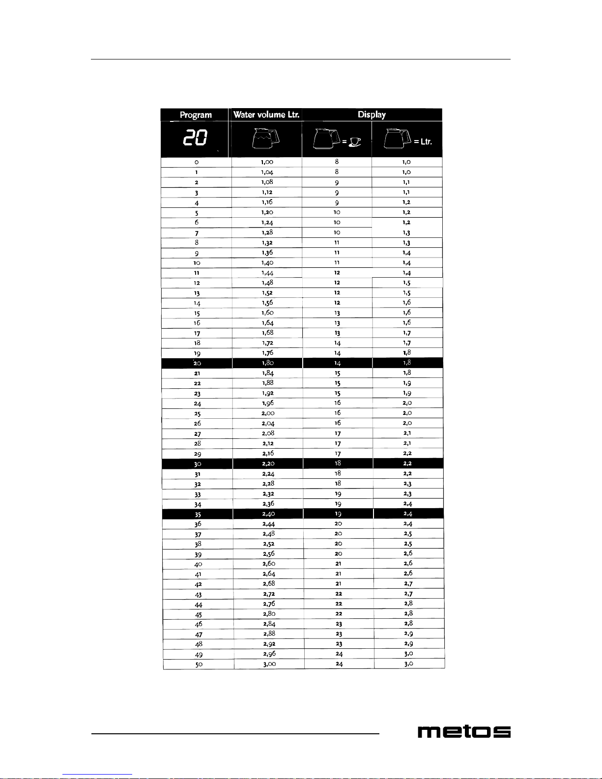
Both the M and the MT mode ls a re suppli ed as st andard set to make cof fee usin g 1, 8 lit res
of water (14 cups). If this is too much or too little, or if you are using an MT model in
combination wit h a therm os j ug with a greate r cap acit y, you ca n adju st t he qua nti ty as follows:
• Press the selection button (5.4) and hold it in, and then press the start/stop button
(5.5) once. A number will appear in the display.
• Release both buttons. The display will show the set value. The standard setting is
20 (1.8 l. / 14 cups).
• Press the s electi on button (5 .4) to increas e the amoun t. Each inc rease i n the displa y
puts appr oxima tely 4 m l more wate r in t he j ug. Use the tab le besid e. To reduc e th e
quantity: go through the table until it restarts after 50. The range runs from
0,1,2,3,4 ..... 50.
• Now wait for 6 seconds. The selec ted quantity is now saved.
Page 21
8.5.2008 Rev. 2.1
Operation instructions
15
Page 22

8.5.2008 Rev. 2.1
Operation instructions
16
Setting of the display to show cups or litres
The appliance i s facto ry se t to dis play the nu mber of c ups. If you want the displ ay to s how
litres, you can adjust it as follows:
• Press the selection button (5.4) and hold it in, the press the start/stop button (5.5)
once. A number will appear in the display.
• Release both th e buttons and then press the start/stop button once again.
• A “C” (Cups) will appear in the display. Change the “C” to an “L” with the selection button.
• Now wait for 6 seconds. The adjustment has now been saved.
Setting the prewet function
This appliance can make coffee using two methods:
• Continue-bre w (“Cb”) (factory setting); The coffee making process begins immediately and will pour hot water over the ground coffee without a waiting time.
• Prewet-brew (“Pb”); part of the hot water is first poured onto the ground coffee.
This causes the coffee to rise so tha t the smells and flavours are released. The coffee making process then begins.
If you want to set the appliance to Prewet brew, this setting can be changed as follows:
• Press the selec tion button (5.4) and hold it in. Then press the start/s top button on ce.
A number will appear in th e dis play.
• Release both buttons and then press the start/stop button twice. “Cb” (Continuebrew) wi ll appear in th e d is p l ay .
• Use the selection button to change “Cb” into “Pb” (Prewet brew).
• Now wait for 6 seconds. The adjustment has now been saved.
Setting the water temperature of the water boiler
On delivery the tempera tur e of the water boil er is se t approx. 90°C. Wi th the tuni ng poi nt
(12.3) the temperature of the water boiler can be increased/reduced between 84 - 98°C.
Use a sm all s cre w dr ive r for thi s. To r edu ce th e te mper atu re, turn left . To i ncr ease , tur n
right.
In high altitude areas (>2000) the water will boil sooner because of lower atmospheric
pressure. Tune the temperature of the water so, that it wil l not boil.
The manufacturer is unable to ac cept any liabi lity for the con sequences of alt ered settin gs.
Page 23

8.5.2008 Rev. 2.1
Operation instructions
17
4.3 Maintenance
4.3.1 Cleaning of the appliance and accessories
The appliance must not be submerged or sprayed.
• Clean the outs ide of the ap pliance with a c lean, damp clot h, if nece ssary using mild
(non-abrasive) cleaning agent.
• Do not use an abrasive, as this will leave scratches and dull patches.
• The glass jugs and the basket filter can be washed normally and rinsed clean.
Please note, however , t hat it is in advi sable t o c lean t he baske t fi lter in an i ndust rial
dish washer as its lightness may cause it to float and sustain damage.
• The thermos jug, thermos jug with pum p and the filter ca n be rinsed wit h hot water .
• The coffee deposit in the coffee jugs and the filter can be cleaned with coffee fur
remover. The appl iance is suppli ed with one s achet of coffee fur re mover. It is e asy
to use.
4.3.2 Removing coffee deposits from glass jug and filter
• Fill a tra y with approx. 5 litres of warm water and dissolve a sachet (10 gr) of coffee fur remover in it.
• Place the parts you want to clean in this solution and leave them to soak for 15 to
30 minu tes.
• Then rinse them several times with hot water, and repeat when necessary.
• Sprinkle the powder on to heavily soiled parts and clean them with a wet brush.
4.3.3 Removing co ffee deposits from thermo s jug
• Dissolve a quantity of coffee fur remover in warm water: use approx. 2 grams per
litre.
• Fill th e th er m o s ju g wi t h th i s sol ution .
• Leave the solution to soak for 15 to 30 minutes, then pour it away.
• Thoroughly rinse the jug several times with hot water.
Page 24

8.5.2008 Rev. 2.1
Operation instructions
18
4.3.4 Descaling
Stay close to the appliance when performing maintenance. It is advisable to wear safety
glasses and protective gloves when descaling the appliance. Flush the appliance at least
two times after descaling it. Wash your hands thoroughly after desca ling the appliance .
Observe the descali ng intervals indicated by the descale indicator light. Overdue maintenance to the heating system ca n result in high re pair costs and annul ment of the guarant ee.
It is reco mmend ed to d escal e the c offe e maki ng sec tion a nd the w ater b oiler in su ccess ion .
Scale deposits are left in the heating system when the appliance is used. The amount of
scaling depends on the hardness of the water being used. The appliance is fitted with a
descale indica tor light (5. 2), whic h ligh ts up whe n th e heati ng sys tem has proc ess ed a certain quantity of water and has to be descaled. The appliance continues to work so that it
can be descaled when it is not being used.
• Before descaling the appliance, carefully read the instructions for use of the scale
remover.
• Slide an empty basket filter and place an empty jug under it.
• Remove the cap (8) and place the funnel (supplied) into the descalin g opening.
• Dissolve on e sach et (50 gr) of scal e remove r in 0.5 litre o f warm water (approx . 6070ºC).
• Carefully pour half of the solution into the descaling opening (8) using the funnel.
• Switch on the a ppli ance usi ng the s witch (1). Select 2 cups using t he sele ction bu tton (5.4) and press the start/stop button (5.5). The solution will now run through
the hea ti n g s y st em and dis c harge in to th e jug.
• Wait until the ‘coffee ready’ signal sounds. The solution will now react with the
deposits in the heating system.
• After the waiti ng tim e, repeat points 5 and 6.
• Wash away the solut ion in the jug once the filte r has finished dripping.
• Remove the funnel and replace th e cap.
• After descaling the appliance, flush the system by following the coffee brewing
procedure twice but without using filter paper or coffee. Remember to empty the
jug in the meantime.
• Switch off the appli ance and thoroughly cle an the basket filter and the jug.
• The appliance is now ready for use.
4.3.5 Switching-off the descale indicator light
• Press the programme button (5.4) for 6 seconds; the descale indicator light (5.2)
will go out.
• The control system resumes registering the number of brewing processes.
Page 25

8.5.2008 Rev. 2.1
Operation instructions
19
4.3.6 Descaling the water boiler
Leave the lid of the water boiler open during the descaling process.
• Before descalin g the water boi ler, careful ly read the ins tructions for use o n the descaling ag e nt .
• Switch the water boiler off when the temperature ok indicator light (12.2) is on.
Leave the water boiler swi tched off during the whole descaling process.
• Draw off approx. 1.5 litres of hot water using the no-drip tap (11) and dissolve 2
sachets of 50 grams of descaling agent in it.
• Pour the s olut ion int o the wat er boi le r. This wi ll s tar t a ( fizzy) r eact ion on the s cal e
deposits.
• Leave this solution during 10 minut es to soak in.
• Regularly spread the solution over the scaled parts in the hot water boiler using a
brush. Draw off some solution and pour it back immediately.
• The entire water boiler can be emptied by using the water drain (22) on the back
of the appliance.
• Make su r e th at th e en d of th e ta p ho se is in the sin k.
• Pull the tap pl ug together with approx . 20 cm hose out of its compart ment. Remov e
the plug by squeezi ng the hose just before the seal plug. Warning: T he water is still
hot.
• Draw the water boiler completely empty and rinse well using clean warm water.
Rinse away all the solution.
• Close the tap hos e and push it back into its com partment.
• Switch the water boiler on/off (13). The water boiler will fill up again.
• If there is stil l scale in th e w ater boiler, repea t steps 3 to 9.
• Before use, rinse the no-drip tap once more by drawing off approx. 1 litre of hot
water.
• The water boiler is now ready for use.
Page 26
8.5.2008 Rev. 2.1
Installation
20
5. Installation
5.1 General
5.1.1 Unpacking
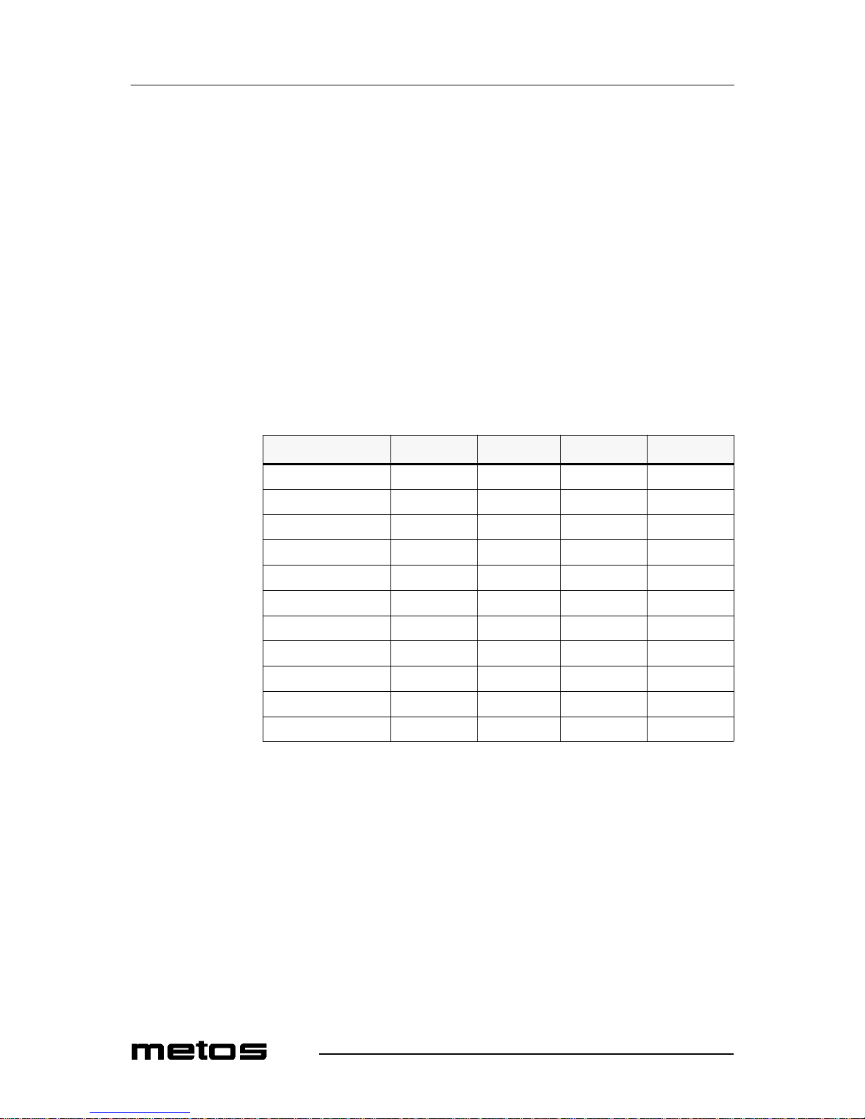
The machine has been carefully packed to preven t damage being ca used to your new coffee maker. Remov e the packing c arefully without using s harp objects. Check if the appliance is complete. The appli ance is deliv er ed with the following acces sories:
Please contact your dealer if any parts are missing or damaged.
M 200W M 202W MT 200W MT 202W
Glass jug 2 4 - Thermos container - - 1 2
Basket filter 1 2 1 1
Filter paper (25 pcs.) 1 1 1 1
Coffee measuring cup 1 1 1 1
Water measuring cu p - - 1 1
Funnel 1 1 1 1
Water connection h ose 1 1 1 1
Manual 1 1 1 1
Synthetic dr ip tray - - 1 2
Stainless steel drip tra y 1 1 1 1
Page 27

8.5.2008 Rev. 2.1
Installation
21
5.2 Installation
5.2.1 Preparation for positioning the appliance
Water always remains in the heating system: for this reason the appliance must not be
placed in an are a w h er e the tem p er at u r e can fall bel ow freezin g p oi n t.
• Position the appliance at bu ffet height on a firm, level base that can bear the weight
of the appliance when it is filled.
• Position the appliance level and in such a way that it cannot cause any damage if
it leaks.
• The water supply pipe (G3/4” pipe 15 mm) and the power connection must be located w it h in a half metr e of the applianc e.
• The owner must have these installation-technical preparations performed by qualified engineers in accor dance with general and local regulation s.
• The service engineer may only connect the appliance to the prepared connectio ns.
5.2.2 Electrical connections
Supply voltages and frequencies can differ between countries. Check if the appliance is
suitable for con necti on to the local power main s. Check if t he details on the type pla te correspond. Connect the appliance to an earthed wall socket.
5.2.3 Connection to the water mains
Connect the appliance usi ng the water hose to an easily accessible cold water tap that can
be quickly closed if problem s arise.
5.2.4 Water drainage
If the reservoir is overfilled owing to a defect, the excess water will be discharged via the
water drain at the bottom of the appliance. Make allowance fo r this when positioning the
appliance.
Page 28
8.5.2008 Rev. 2.1
Installation
22
5.2.5 Setting the descale indicator
Scale deposits are left in the heating system when the appliance is used. The amount of
scaling depends on the hardness of the water being used. The appliance is fitted with a
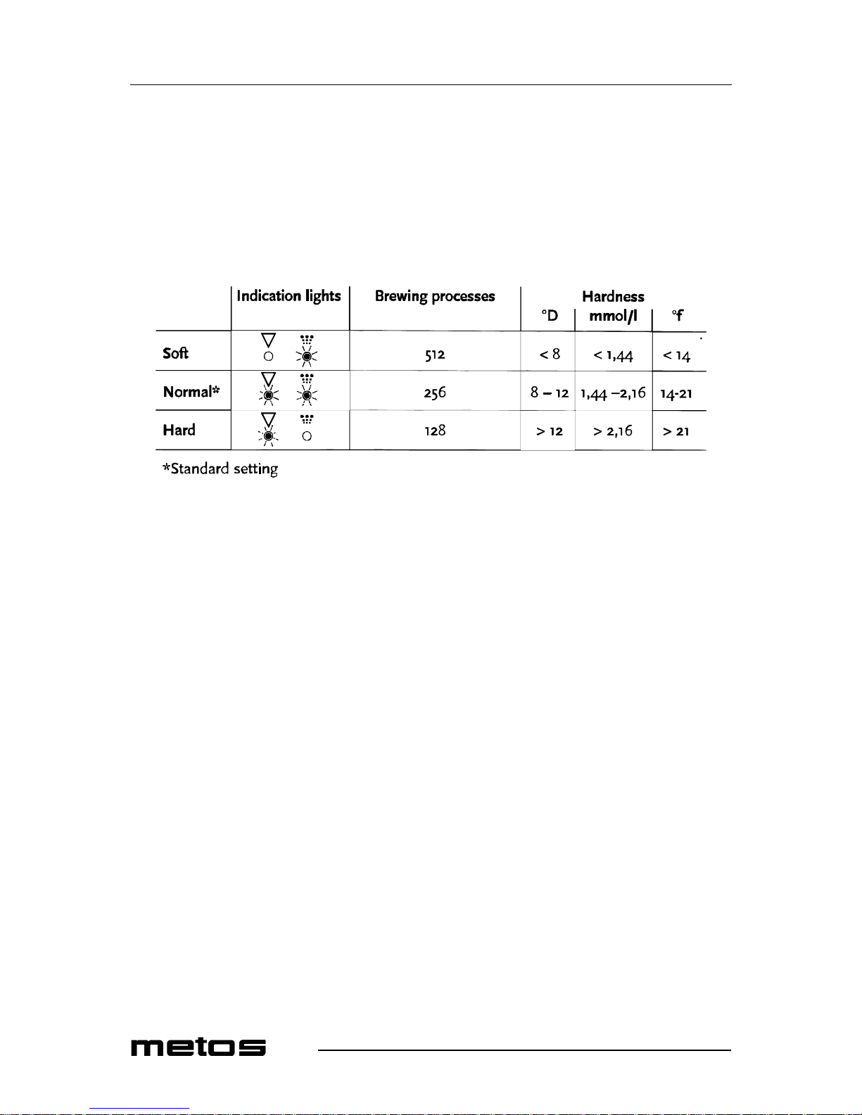
descale light (5. 2), which li ghts up when t he hea ting s ystem h as process ed a c ertai n quantity of water an d has to be desc aled. The appli an ce contin ues to work s o that it can be des caled when it is not being used.
If you are unaware of the hardness of your mains water, you are advised to contact your
local water supply company.
Set the applianc e to your water hardness as fo llows, using the ta ble above as a guideline.
• Switch off the appliance (1).
• Hold in the programme button (5.4) and switch the appliance back on.
• Press the programme button (5.4) until the right indicator light (5.2/5. 3) lights up.
(E.g. only the red la mp should light up for hard water).
• Wait for 6 seconds. The water hardness has now been set.
5.2.6 Resetting the descale indicator light
After the descaling proc edur e (see chapte r ‘Descali ng’) hol d in th e programme butt on for
6 seconds. The descaling indicator light will now go out.
Water
hardness
Page 29
8.5.2008 Rev. 2.1
Troubleshooting
23
6. Troubleshooting
Have al l r ep ai r s to th e el ec tr i cal system p er f o rm ed by a qualifie d ser vi c e technic ia n .
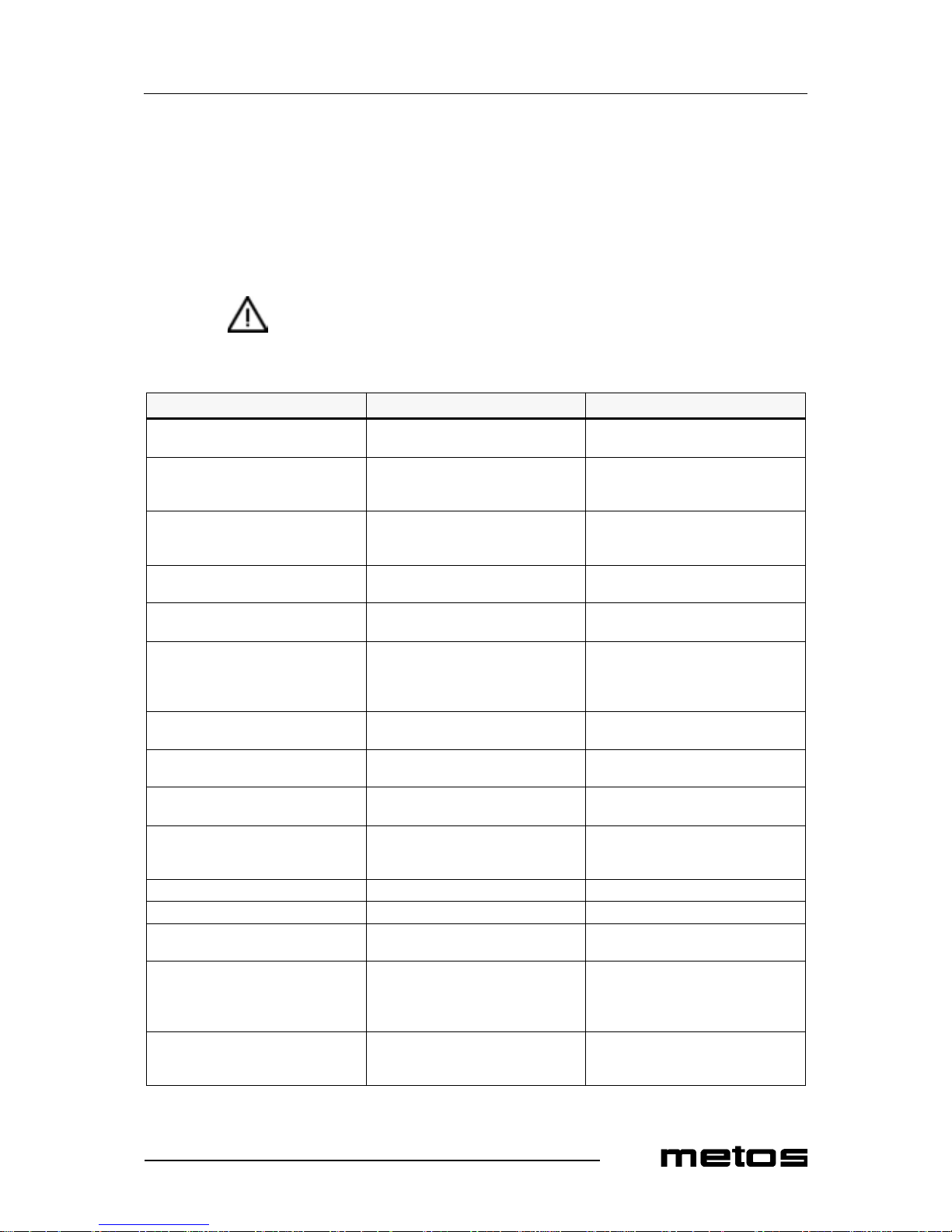
If your appliance is not functioning correctly, use the troub leshooting guide below to see
whether you can resolve the prob lem yourself. If not, plea s e contact your dealer.
Symptom Possible cause Action
The appliance is not wor king and the
lamps in the switch are not li ghti ng up.
The fuse in the fuse box has been triggered, the group is too loaded heavily.
Replace the fuse or reset it. Connect
the appli ance to a sep arate gro up.
The brewin g process indicator light is
flickering, no water is getting into the
filter.
The jug indicator is not registering a
jug. There is no jug under the filter.
Position a jug, use the correct jug .
The brewin g process indicator light is
on, but no water is getting in to the filter.
The dry-boil protection has been triggered.
Reset the dry-boil protection.
The descale indicator light has come
on.
The scaling deposits in the heating system exceed the set limit.
Descale t he appliance.
The descale i ndi cato r li ght re main s on
after descaling the appliance.
The appliance has not yet be en reset. Press the program me button for 6 sec-
onds. The light will go out.
Steam coming from the filter. The appliance was not descaled when
indicated by the descal ing indicat or
light or the wrong water settin g h as
been applied.
Descale t he appliance.
Coffee is dripping out of the filter
when there is no jug under it.
The leak stop valve on the outlet of the
filter is soiled or damage d.
Clean the filter and check the leak stop
valve for damage.
The coffee is too strong. Too much coff ee has been placed in
the filter.
Reduce the amount of coffee.
The coffee is too weak. Not enough co ffee has been placed in
the filter.
Increase the amount of coffee.
The water distributor is soiled, so that
the coff ee is not being complete ly
drenched.
Unscrew the water dist ributor and
clean it.
The coffee is not hot enough There is no lid on the jug Use the lid.
The jug is too full or is overflowing. The set quantity is too high. Lower the qua ntity.
Not enough coffee is getting into the
jug.
The set quantity is too low . Increase the quantit y.
E1 (filling time error). Appliance fills too slowly, the water
supply is blo cked.
Check the water supply. Fully open the
tap. Increase th e w at er pre ssure.
Switch the appl iance on and off . The
error re port will d isappear.
An E2, 3, 4, 5, 6 appea rs in th e di spla y
and both indication lights flicke r.
The control unit is reporting a defect
that can on ly be resol ved by a servi ce
technician.
Contact dealer or se rvice technician.
Page 30
8.5.2008 Rev. 2.1
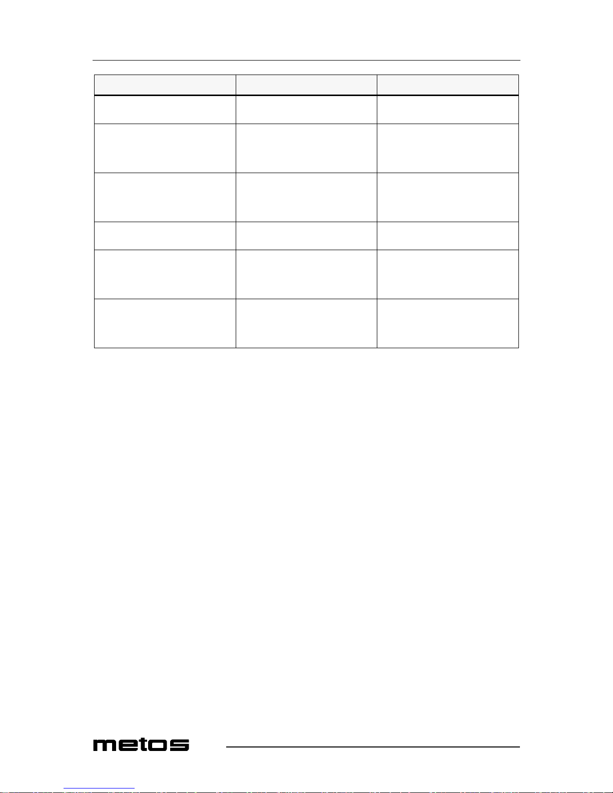
Troubleshooting
24
Symptom Possible cause Action
After filling until the max. level, the
heating is not switche d on.
The dr y- b oil prot ec tion has been
switched off.
Switch the dr y-boil prot ection back on.
The water bo iler does not heat u p, both
indicator lights ar e flickering.
The safety electrode has turned off the
system, the wate r lev el is t oo high. The
lower electrode needs to be descaled.
Switch off the water boiler. Descale
the water b oiler and the electrodes.
Please note: after descaling, the electrodes need to be free acid.
The water temperature is set too high.
The water is boiling and to uches the
safety electrode which turns off the
system.
Switch off the water boiler. Set the water temperature at a lower level. Clean
the electrodes.
After des caling the water boiler does
not fill up.
The electrodes are not free of acid. Switch the water boiler off and then
turn it on ag a in .
The water boiler does not heat up or
fills par tia ll y an d switc hes off , bot h in dicator lig hts start to flic k er .
The water boiler fills up too slowly. Open the water supp ly ta p co mpletely.
Check the connection hose on kinks.
Check if the f ilt er of the s oleno id val ve
is clogged up.
The water bo iler does not heat u p, both
indicator lights keep flickeri ng.
Switching the water boil er off and
back on, does not help.
Switch off the appliance. Call for your dealer or service techni-
cian.
Page 31

8.5.2008 Rev. 2.1
Technical specifications
45
8. Technical speci fi cations
Electrical diagram M200W
Electrical diagram M200W
Electrical diagram M202W
Electrical diagram M202W
Electrical diagram MT200W
Electrical diagram MT200W
Electrical diagram MT202W
Electrical diagram MT202W
Installation drawing M200W, M202W
Installation drawing MT200W, MT202W
Page 32
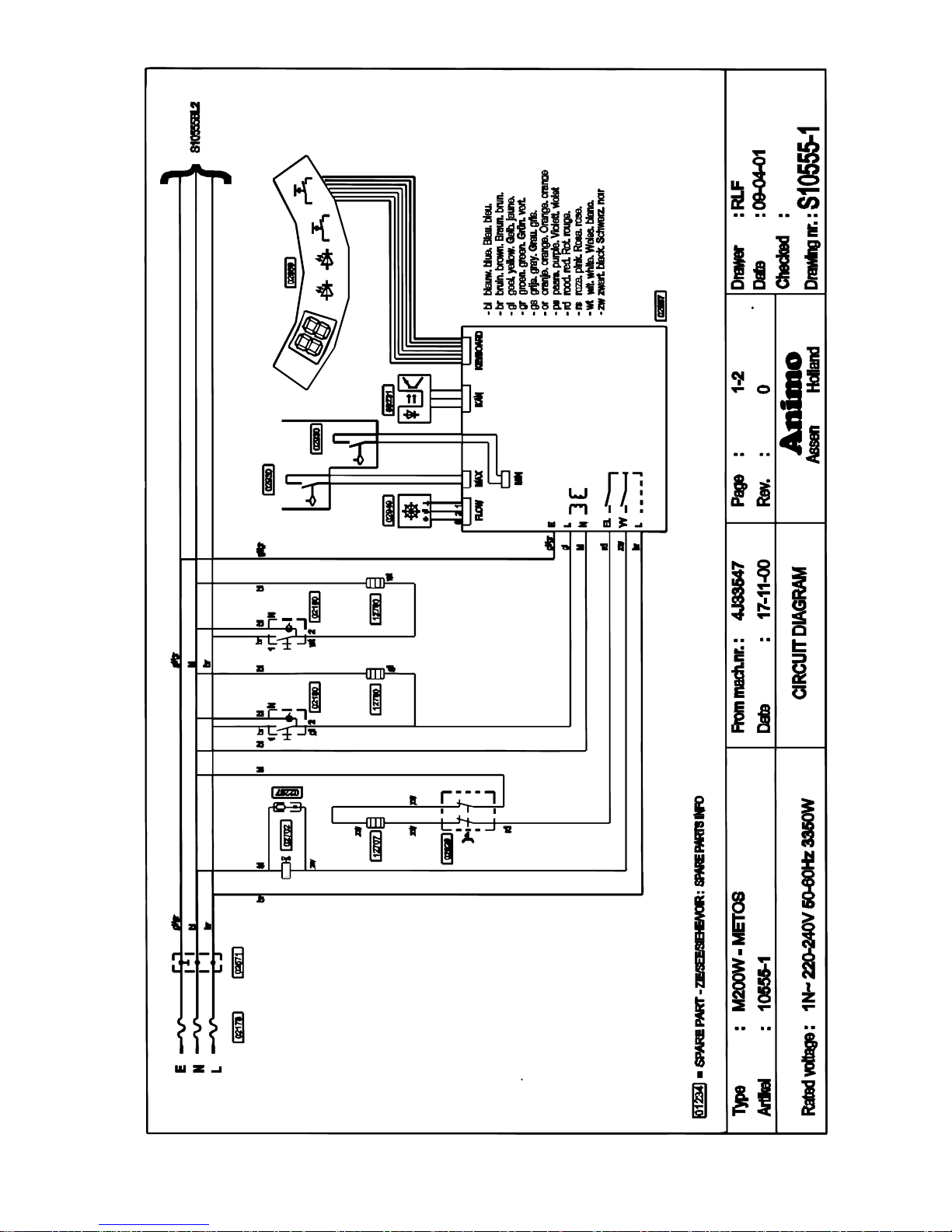
Electrical diagram M200W
blå. sininen.
brun. ruskea
gul. keltainen.
grön. vihreä.
grå, harmaa.
orange. oranssi
purpur. purppura
röd. punainen
pink. vaaleanpunainen
vit. valkoinen
svart. musta
Page 33
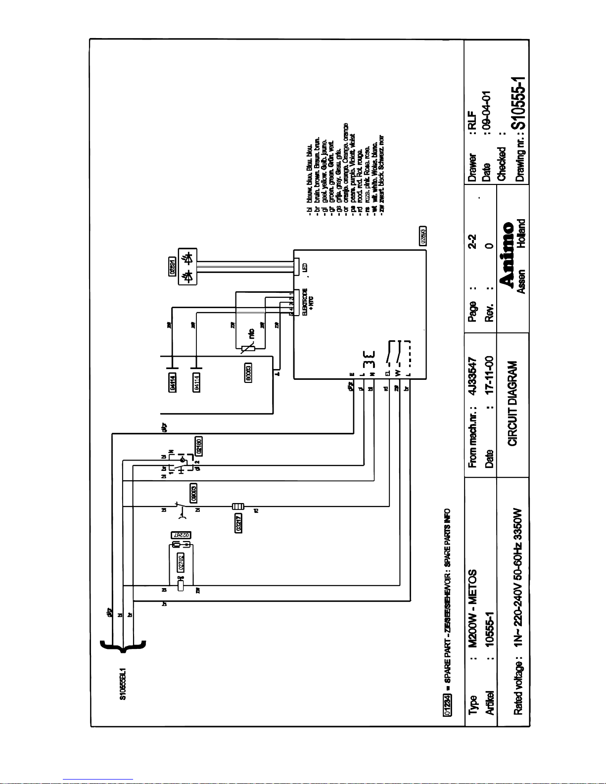
Electrical diagram M200W
blå. sininen.
brun. ruskea
gul. keltainen.
grön. vihr eä.
grå, harmaa.
orange. oranssi
purpur. purppura
röd. punainen
pink. vaaleanp una inen
vit. valkoinen
svart. musta
Page 34
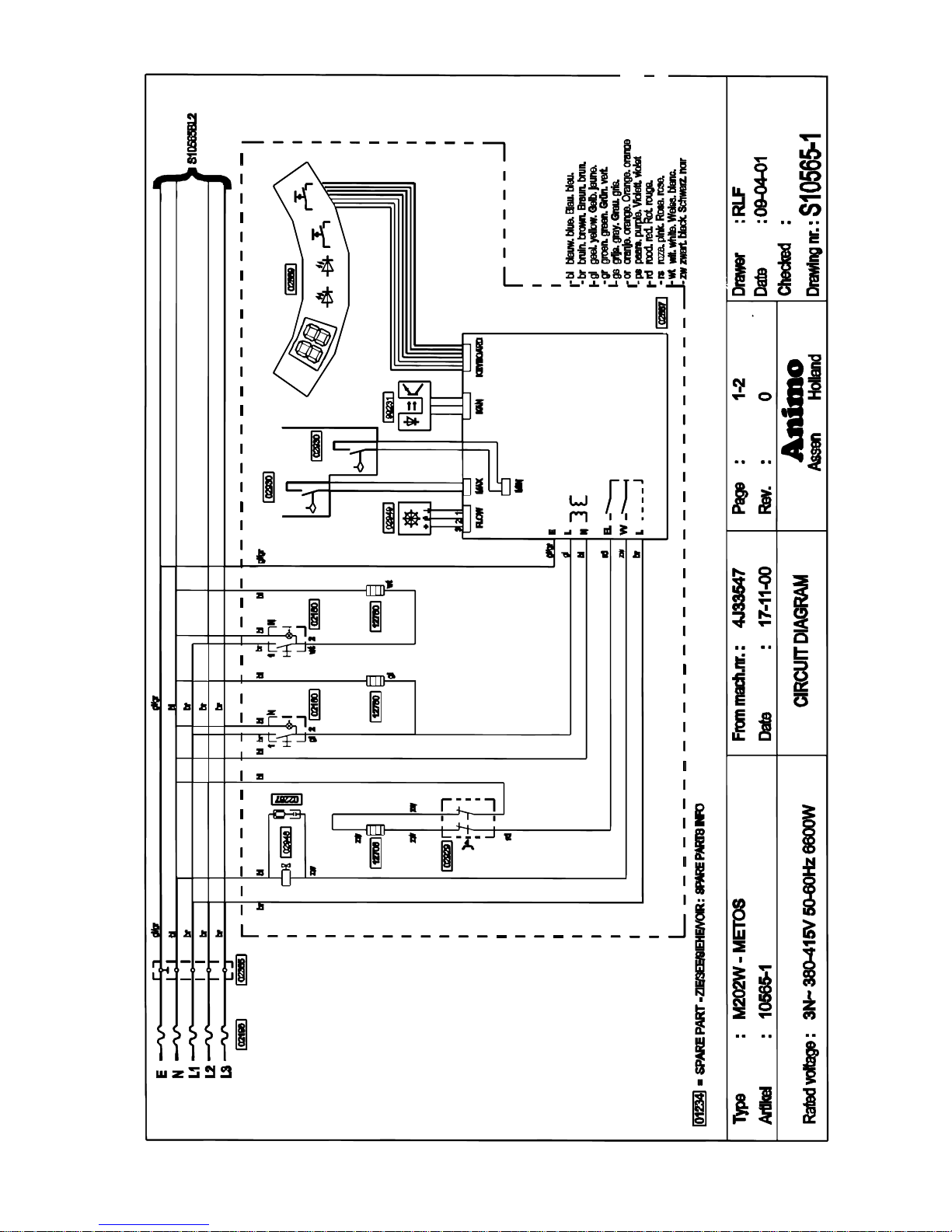
Electrical diagram M202W
blå. sininen.
brun. ruskea
gul. keltainen.
grön. vihreä.
grå, harmaa.
orange. oranssi
purpur. purppura
röd. punainen
pink. vaaleanpunainen
vit. valkoinen
svart. musta
Circuit diagram left
Kretsschema vänster
Piirikaavio vasen
Page 35
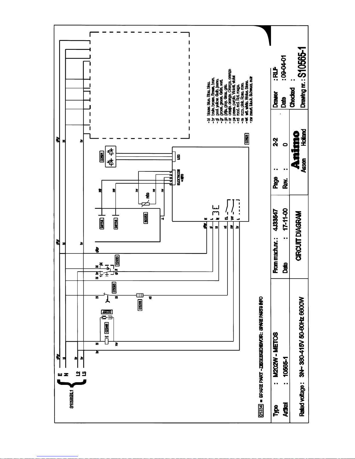
Electrical diagram M202W
blå. sininen.
brun. ruskea
gul. keltainen.
grön. vihreä.
grå, harmaa.
orange. oranssi
purpur. purppura
röd. punainen
pink. vaaleanpunainen
vit. valkoinen
svart. musta
Circuit diagram right, see left
Kretsschema höger, titta på vänster
Piirikaavio oikea, katso vasen
Page 36
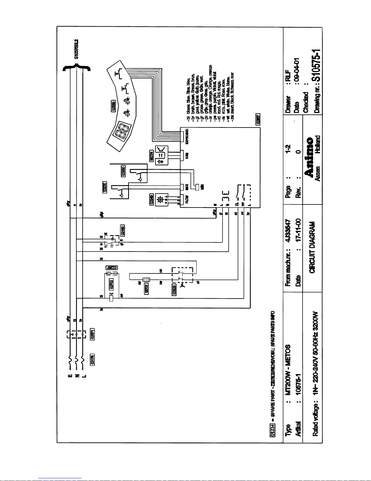
Electrical diagra m MT200W
blå. sin inen.
brun. ruskea
gul. keltainen.
grön. vihreä.
grå, harmaa.
orange. oranssi
purpur. purppura
röd. pu nainen
pink. vaaleanpunainen
vit. valkoinen
svart. musta
Page 37
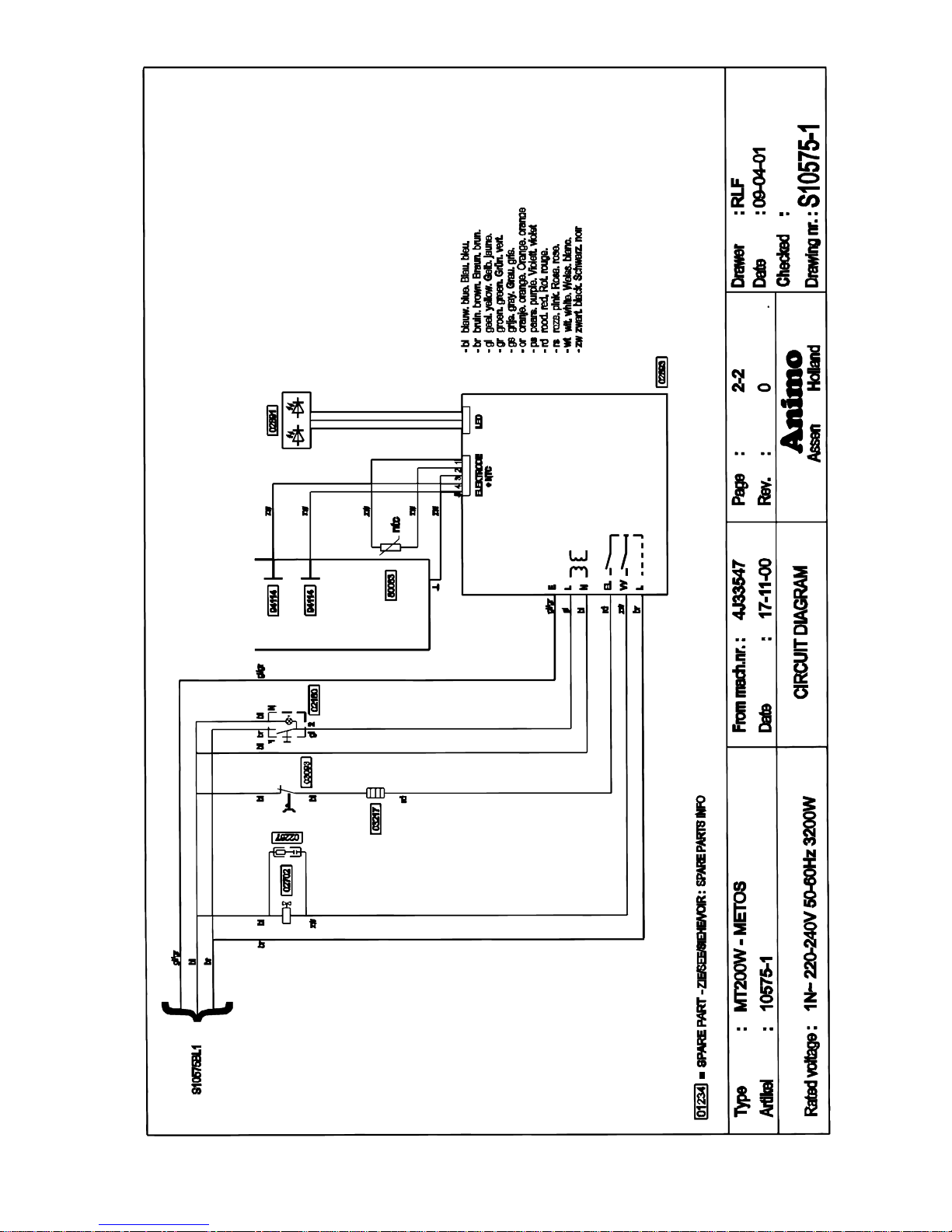
Electrical diagra m MT200W
blå. sininen.
brun. ruskea
gul. keltainen.
grön. vihreä.
grå, harmaa.
orange. oranssi
purpur. purpp ur a
röd. punainen
pink. vaaleanpunainen
vit. valkoinen
svart. musta
Page 38
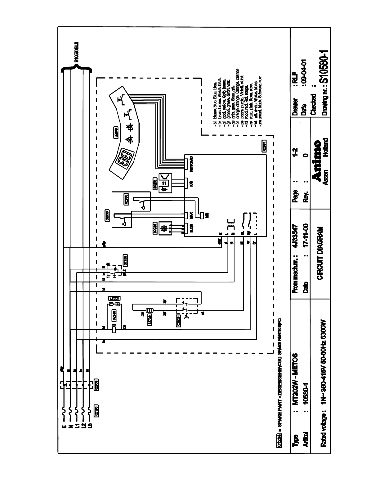
Electrical diagra m MT202W
blå. sininen.
brun. ruskea
gul. keltainen.
grön. vihreä.
grå, harmaa.
orange. oranssi
purpur. purppura
röd. punainen
pink. vaaleanpunainen
vit. valkoinen
svart. musta
Page 39
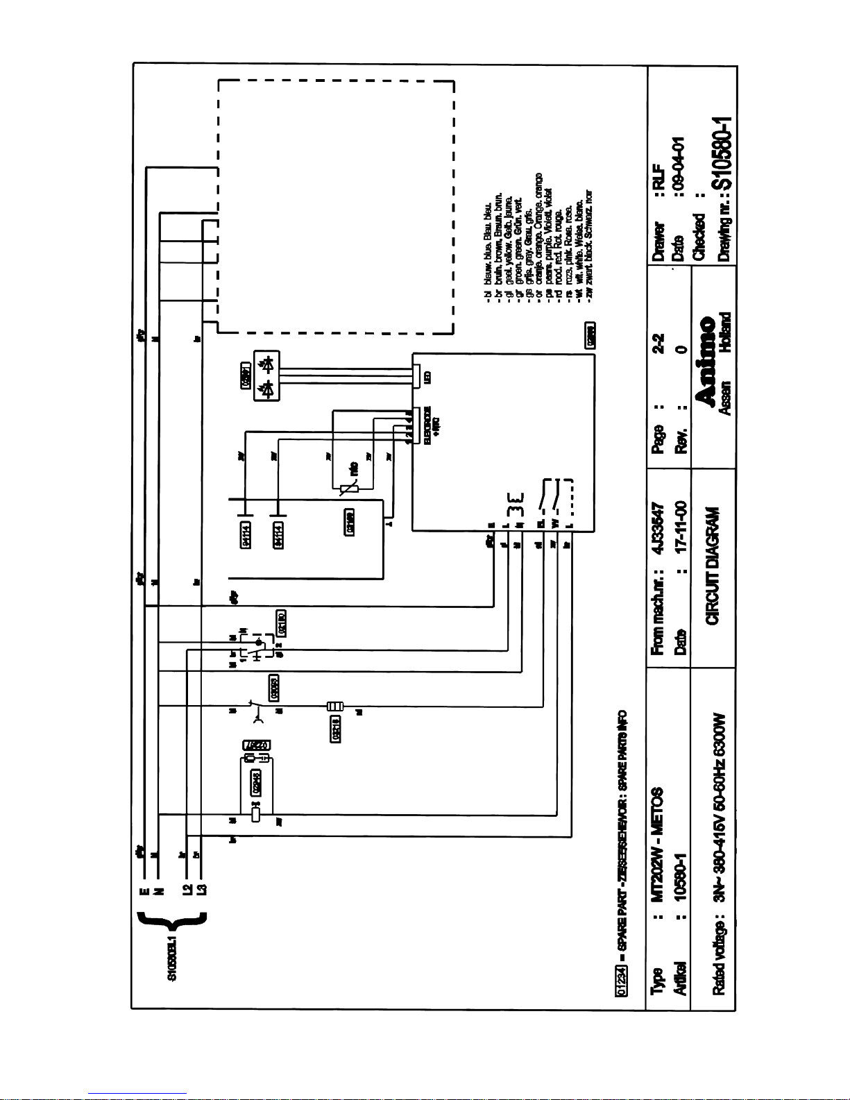
Electrical diagra m MT202W
blå. sininen.
brun. rusk ea
gul. keltainen.
grön. vihr eä.
grå, harmaa.
orange. oranssi
purpur. purppura
röd. punainen
pink. vaaleanpunainen
vit. valkoinen
svart. musta
Circuit diagram right, see left
Kretsschema vänster, titta på höger
Piirikaavio vasen, katso oikea
Page 40
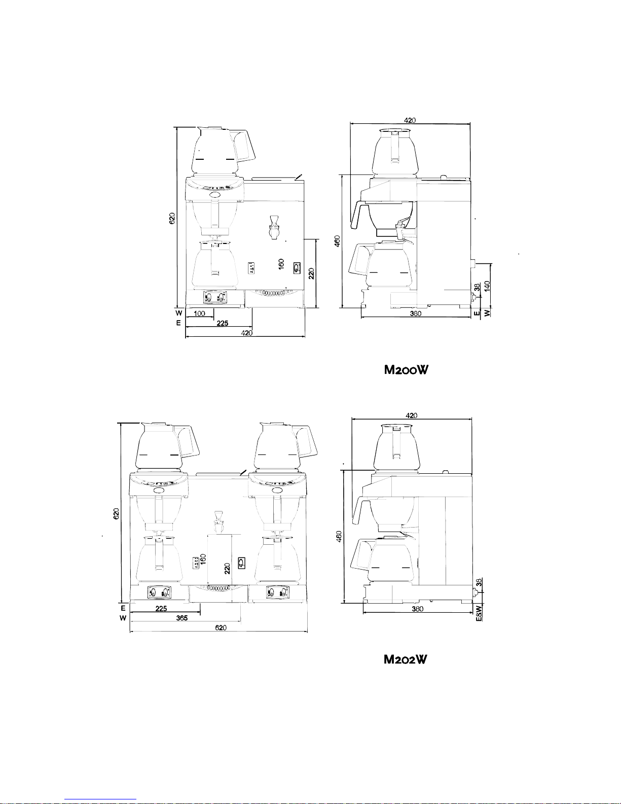
Installation drawing M200W, M202W
E = Electric connection / Elanslutning / Sähköliitäntä
W = Water connection / Vattenanslutning / Vesiliitäntä
Page 41
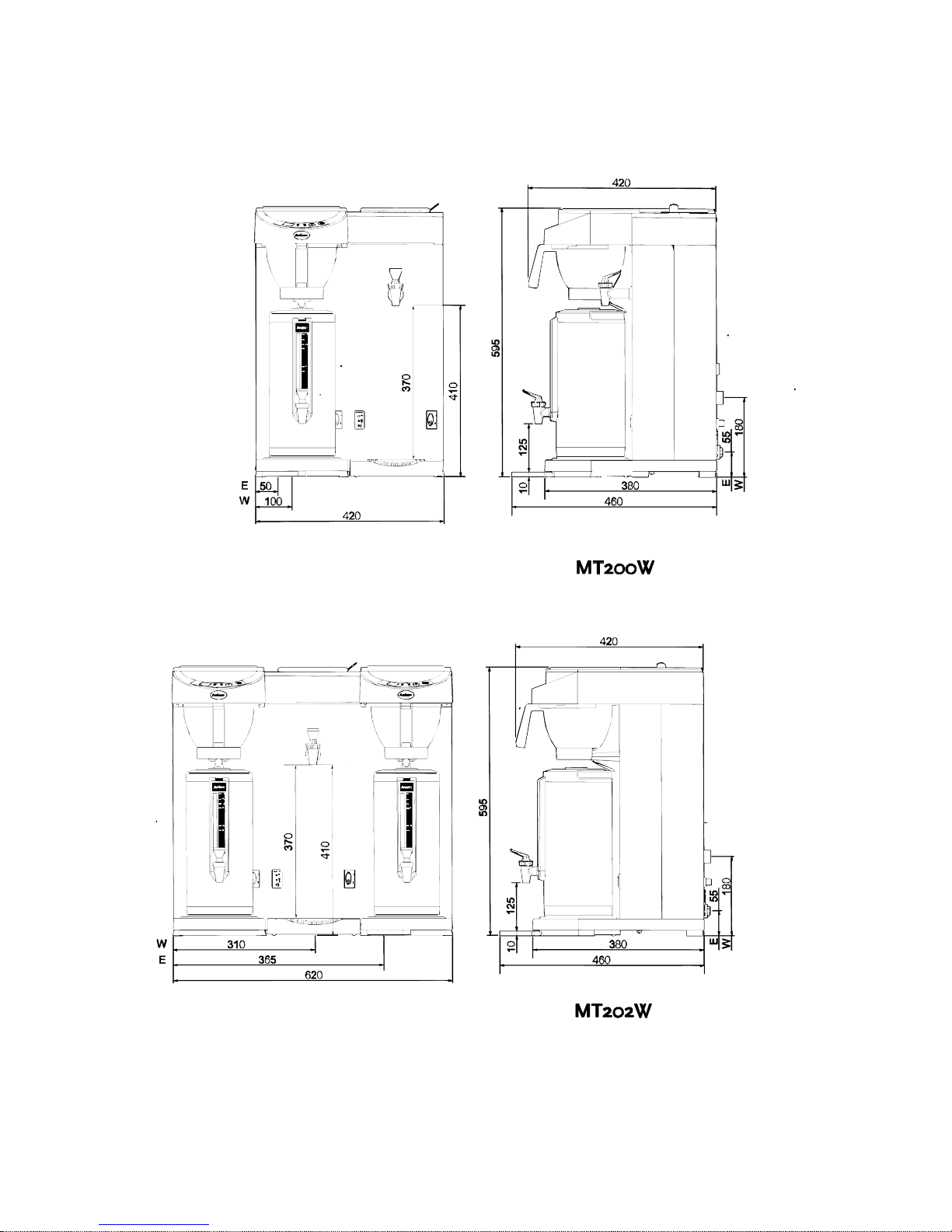
Installation drawing MT200W, MT202W
E = Electric conn ection / Elan slutning / Sähköliitäntä
W = Water connection / Vattenanslutning / Vesiliitäntä
Page 42
8.5.2008 Rev. 2.1
Technical specifications
56
Item Type Specification
Buffer stock coffee M200W 3.6 l. / 28 cups
Buffer stock coffee M202W 7.2 l. / 56 cups
Buffer stock coffee MT20 0W 2.4 l. / 19 cups
Buffer stock coffee MT202W 4.8 l. / 38 cups
Hourly coffee capacity M200W,MT200W 14 l. / 112 cups
Hourly cof fee capacit y M202W,MT202W 36 l. / 288 cups
Jug filli ng time M200W approx. 8 min.
Jug filli ng time M202W approx. 6 min.
Jug filli ng time MT200W,MT202W approx. 8 min./ 2.4 l.
Coffee amount M200W,M202W,MT20
0W,MT202W
1 - 3 l.
Buffer stock hot water M200W,M202W,MT20
0W,MT202W
1.8 l. / 14 cups
Hour capac ity hot water M200W,MT200W 16 l. / 128 cups
Hour capac ity hot water M202W,MT202 W 21 l. / 168 cups
Heatin g ti me w at er bo ile r M200W,MT200W 11 min.
Heating time water boiler M202W,MT202W 9 min.
Supply voltage M200W,MT200W 220-240V
Supply voltage M202W,MT202 W 3N 380-415V
Frequency M200W,M202W,MT20
0W,MT202W
50-60Hz
Total output M200W 3350W
Total output M202W 6600W
Total output MT200W 3200W
Total output MT202W 6300W
Filter pap er M200W,M202W, MT20
0W,MT202W
90 / 250
Min. water pressure M200W,M202W,MT20
0W,MT202W
0.02 Mpa (0.2 bar)
Max. water pressure M200W,M202W,MT20
0W,MT202W
1 Mpa (10 bar)
Empty weight M200W,MT200W 14 kg
Empty weight M202W 22 kg
Empty weight MT202W 23 kg
Transport dim ensio ns ( LxWxH) M200W 600x475x520 mm
Transport di mensio ns ( LxWxH) M202W 600x700x520 mm
Transport dim ensio ns ( LxWxH) MT200W 485x4 45x910 mm
Transport di mensio ns ( LxWxH) MT202W 700x445x910 mm
Page 43

 Loading...