

Metos Culino 200S, Culino 60S, Culino 400S, Culino Combi 40S, Culino Combi 60S Installation And Operation Manual
...
CULINO KETTLE
CULINO / CULINO COMBI
DIRECT STEAM HEATED
TYPE: 40S, 60S, 80S, 100S, 150S, 200S, 300S, 400S
Accessories
MIXER
COOLING ATTACHMENT
TIMER
AUTOMATIC WATER FILLING
Installation and Operation Manual
S/N: 10911002080010 Valid from: 14.6.2012 Rev.: 1.7
4215209, 4215210, 4215211, 4215212, 4215213, 4215214, 4215244, 4215547, 4215972, 4215973,
4215974, 4215975, 4215976, 4215978, 4215979, 4215980


15.6.2012 Rev. 1.7
Dear Customer,
Congratulations on deciding to choose a Metos appliance for your kitchen activities. You
made an excellent choice. We will do our be st to make you a satisfied Metos customer
like thousands of customers we have around the world.
Please read this manual carefully. You will learn correct, safe and efficient working methods in order to get the best possible benefit from the appliance. The instructions and hints
in this manual will give you a quick and easy start, and you will soon note how nice it is
to use the Metos equipment.
All rights are reserved for technical changes.
You will find the main technical data on the rating plate fixed to the equipment. When you
need service or technical help, please let us know the serial number shown on the rating
plate. This will make it easier to provide you with correct service.
For your convenience, space is provided below for you to record your local Metos service
contact information.
METOS TEAM
Metos service phone number:...............................................................................................
Contact person:....................................................................................................................

15.6.2012 Rev. 1.7

15.6.2012 Rev.
1. General .......................................................................................................... 1
1.1 Symbols used in the manual .......................................................................................... 1
1.2 Symbols used on the appliance ...................................................................................... 1
1.3 Checking the relationship of the appliance and the manual .......................................... 1
2. Safety .............................................................................................................. 3
2.1 Safety features ............................................................................................................... 3
2.2 Emergency-stop switch ................................................................................................. 3
2.3 Warnings ........................................................................................................................ 4
3. Functional description .................................................................................. 5
3.1 Operating principle ........................................................................................................ 5
3.2 Construction and control panel ...................................................................................... 6
4. Operating instructions ................................................................................. 9
4.1 Before use ...................................................................................................................... 9
4.1.1 After the installation .............................................................................................. 9
4.1.2 Before the first use ................................................................................................. 9
4.1.3 Daily ....................................................................................................................... 9
4.1.4 Quarterly ................................................................................................................ 9
4.1.5 Yearly ................................................................................................................... 11
4.1.6 Emptying of surplus condensate water ................................................................ 11
4.1.7 Total emptying of the kettle jacket ..................................................................... 11
4.2 Operation ..................................................................................................................... 12
4.2.1 Cooking ................................................................................................................ 12
4.2.2 Tilting the kettle ................................................................................................... 13
4.2.3 Filling water into the kettle (Culino 40-400) ....................................................... 14
4.2.4 Mixer operation .................................................................................................... 14
4.2.5 Manual cooling C1 (optional) .............................................................................. 22
4.2.6 Operation of the timer (optional) ......................................................................... 24
4.2.7 Automatic water filling (option) .......................................................................... 26
4.3 After use ...................................................................................................................... 28
4.3.1 Cleaning the kettle ............................................................................................... 28
4.3.2 Treatment of stainless steel .................................................................................. 30
4.3.3 Notes on service work .......................................................................................... 31
5. Installation ................................................................................................... 32
5.1 Before installation ....................................................................................................... 32
5.1.1 Transport and reception ....................................................................................... 32
5.1.2 Storage ................................................................................................................. 32
5.1.3 Facilities ............................................................................................................... 33

15.6.2012 Rev.
5.1.4 Unpacking the unit ............................................................................................... 33
5.1.5 Industrial safety during installation ..................................................................... 33
5.2 Installation ................................................................................................................... 33
5.2.1 Installation on subsurface frames cast into the floor ........................................... 34
5.2.2 Installation on surface installation frames ........................................................... 35
5.3 Electrical and water connections ................................................................................. 35
5.3.1 Electrical connection ............................................................................................ 36
5.3.2 Water connection ................................................................................................. 36
5.3.3 Steam and condensate connections ...................................................................... 36
5.4 Ventilation ................................................................................................................... 36
5.5 Other installations ....................................................................................................... 36
5.6 Adjusting the tilting ..................................................................................................... 37
5.7 Testing the kettle ......................................................................................................... 38
5.7.1 Cooking mode ...................................................................................................... 38
5.7.2 Checking the safety valve .................................................................................... 38
5.8 Testing the mixer ......................................................................................................... 40
5.8.1 Checking the functions ........................................................................................ 40
5.8.2 Checking the safety equipment ............................................................................ 40
5.9 Combination of machines ............................................................................................ 41
6. Troubleshooting .......................................................................................... 42
8. Technical specifications ..........................................
.................................... 45

15.6.2012 Rev. 1.7
General
1
1. General
Carefully read the instructions in this manual as they contain important information regarding proper, efficient and safe installation, use and maintenance of the appliance.
Keep this manual in a safe place for eventual use by other operators of the appliance.
The installation of this appliance must be carried out in accordance with the manufacturer’s instructions and following local regulations. The connection of the appliance to the
electric, steam and water supply must be carried out by qualified persons only.
Persons using this appliance should be specifically trained in its operation.
Switch off the appliance in the case of failure or malfunction. The periodical function
checks requested in the manual must be carried out according to the instructions. Have the
appliance serviced by a technically qualified person authorized by the manufacturer and
using original spare parts.
Not complying with the above may put the safety of the appliance in danger.
1.1 Symbols used in the manual
This symbol informs about a situation where a safety risk might be at hand. Given instructions are mandatory in order to prevent injury.
This symbol informs about the right way to perform in order to prevent bad results, appliance damage or hazardous situations.
This symbol informs about recommendations and hints that help to get the best performance out of the appliance.
1.2 Symbols used on the appliance
This symbol on a part informs about electrical terminals behind the part. The removal of
the part must be carried out by qualified persons only.
1.3 Checking the relationship of the appliance and the manual
The rating plate of the appliance indicates the serial number of the appliance. If the manuals are missing, it is possible to order new ones from the manufacturer or the local representative. When ordering new manuals it is essential to quote the serial number shown
on the rating plate.
If language versions have information contradictions, the original language Finnish is the
primary language regarding the information content.

15.6.2012 Rev. 1.7
General
2
This manual covers the following Culino and Culino Combi kettles and all their options:
• direct steam heated Culino kettles 40, 60, 80, 100, 150, 200, 300 and 400 litres
• mixer (Culino Combi)
• cooling attachment (option)
• timer (option)
• automatic water filling (option)
The user panel and the available functions of the Culino kettle are different depending on
the kettle version:

15.6.2012 Rev. 1.7
Safety
3
2. Safety
2.1 Safety features
The kettle is built for 1,5 bar pressure, and the working pressure is 1,0 bar. The working
height is 900 mm.
The double steam jacket is isolated with a third casing jacket, throughout equipped with
a foil and foam insulation, which limits the top temperature of the outer steam jacket under
the skin burn l imit. The control panel works with 12 V l ow voltage. The kettle can be
cleaned with a cleaning hose (IP65). Water jets directed towards the vent holes and control panel from a near distance should be avoided.
The kettle is fitted with many different safety devices to ensure smooth and safe operation.
The safety equipment at the rim behind the kettle includes a pressure gauge, a safety valve
and an automatic vacuum valve. The safety valve opens if the steam pressure exceeds 1,5
bar.
In addition to t he safety valve, the kettle has a built-in electronic temperature control
which operates as a backup safety device of the safety valve. The control does not allow
the steam jacket temperature to exceed 120°C. This temperature corresponds to a 1,0 bar
steam pressure.
A limit switch which is attached to the tilting axle turns off the heating during the tilting.
Due to the safety switch which is on the safety lid it is not possible to start mixing (Culino
Combi), if the safety grid is not in position. The kettle will not tilt, if the lid is on the kettle.
2.2 Emergency-stop switch
All Culino kettles are equipped with an emergency-stop switch, which disconnects the
control circuit and all functions of the kettle and the mixer will be stopped. To restart the
cooking/mixing, turn the emergency-stop switch clockwise until it jumps to its upper position. After this has been done, all other switches and buttons can be activated again.

15.6.2012 Rev. 1.7
Safety
4
2.3 Warnings
Please take careful note of the following instructions and warnings. Further on in this
manual, there are warnings which are to be noted in special operation situations. To prevent damage and accidents, please read the whole manual before attempting to operate the
appliance.
• Culino kettles are to be used only for food preparation. Interacting or corrosive
substances are not to be prepared in the kettle. Note that also long-term effect of
some food preparation substances, such as salt, acetic acid, lemon acid and lactic
acid, can be corrosive.
• To prevent burns, do not during the use touch the inner surface and the rim of the
kettle, safety lid and mixing tool. Do not put your hands, without appropriate protection, above the kettle while cooking.
• Beware of hot steam when removing the lid.
• Do not open the filling and emptying valves and the drain valve of the kettle jacket
when there is pressure in the steam jacket. Releasing hot steam might cause burns.
• Do not stand behind the kettle during tilting.
• The mixer must be turned off before removing the mixing tool.
• Do not push utensils or your fingers through the openings in the safety lid into the
kettle during mixing.
• It is under all circumstances absolutely forbidden to use the mixer without the safety lid.
• To prevent stress injuries do not lift the mixing tool from the kettle when it is in a
vertical position. Tilt the kettle in a horizontal position and remove the mixing tool.
We recommend the use of a trolley to help removing of the mixing tool of larger
kettles (200-400 l).
• After using the kettle, check that the shower gun and the water inlet tap of the kettle
are closed.
• After using the kettle, clean it according to the cleaning instructions given in this
manual to keep the high hygiene level.
• It is forbidden to use the kettle without cover plates or if the cover plates are not
properly fitted.
• The factory pre-set program paramet ers of th e kettle and mixer may on ly be
changed by authorized personnel according to the instructions given by the factory.
• Beware of sharp edges on the sheet construction inside the kettle pillars during installation and service work.
• The following danger of electrical shock mark is fitted on cover plates protecting
electrical components from being touched which would cause danger to life.
The manufacturer will not take responsibility for potential damage caused to units or persons if the given instructions have not been followed.

15.6.2012 Rev. 1.7
Functional description
5
3. Functional description
3.1 Operating principle
The Culino kettle is heated with direct steam provided from the facility’s steam network.
The steam jacket reaches the upper ed
ge of the kettle. The cooking procedure is regulated
by electronic temperature control. The kettle tilts by means of a tilting motor (high tilting).
The inner surface of the kettle and the jacket are of acid proof stainless steel (AISI 316).
All other construction is of stainless steel (AISI 304). The kettle is provided with a third
jacket and it is throughout thermally isolated.
The corrosion resistance of stainless steel is due to a so called passive layer, which is a
very thin chromium oxide film. This film is naturally and fairly quickly formed on the
stainless steel surface when the surface is in contact with oxygen (air). The chromium
oxide film is hard, but in some situations it is possible to damage it with hard materials.
When using steel tools, there is a potential risk of scratching the inner jacket and hence
increased risk of corrosion. Therefore, we recommend using wooden or plastic tools in
the kettle, especially when mixing and scraping.
The motor and power transmission (Culino Combi) are situated below the mixing tool.
The kettle with a mixer is provided with a safety lid having a large lid opening. When the
safety lid is open the mixer does not work. The control panel for both the kettle and the
mixer are in the control pillar.
The optional cooling system is based on cold water circulating inside the steam jacket.
Cold water runs in a connection hose from the water faucet, which is in the control pillar,
to the jacket drain valve and further to the outlet pipe of the upper edge and to the floor
drain, which is in front of the kettle.
The optional programmable timer enables to pre-set the starting and cooking times. When
the program is completed, the cooking temperature is automatically set to the Hold temperature (+ 70°C).
The optional automatic water filling enables filling of the kettle with a desired amount of
water. Thus water filling takes place automatically, without supervision.
15.6.2012 Rev. 1.7
Functional description
6
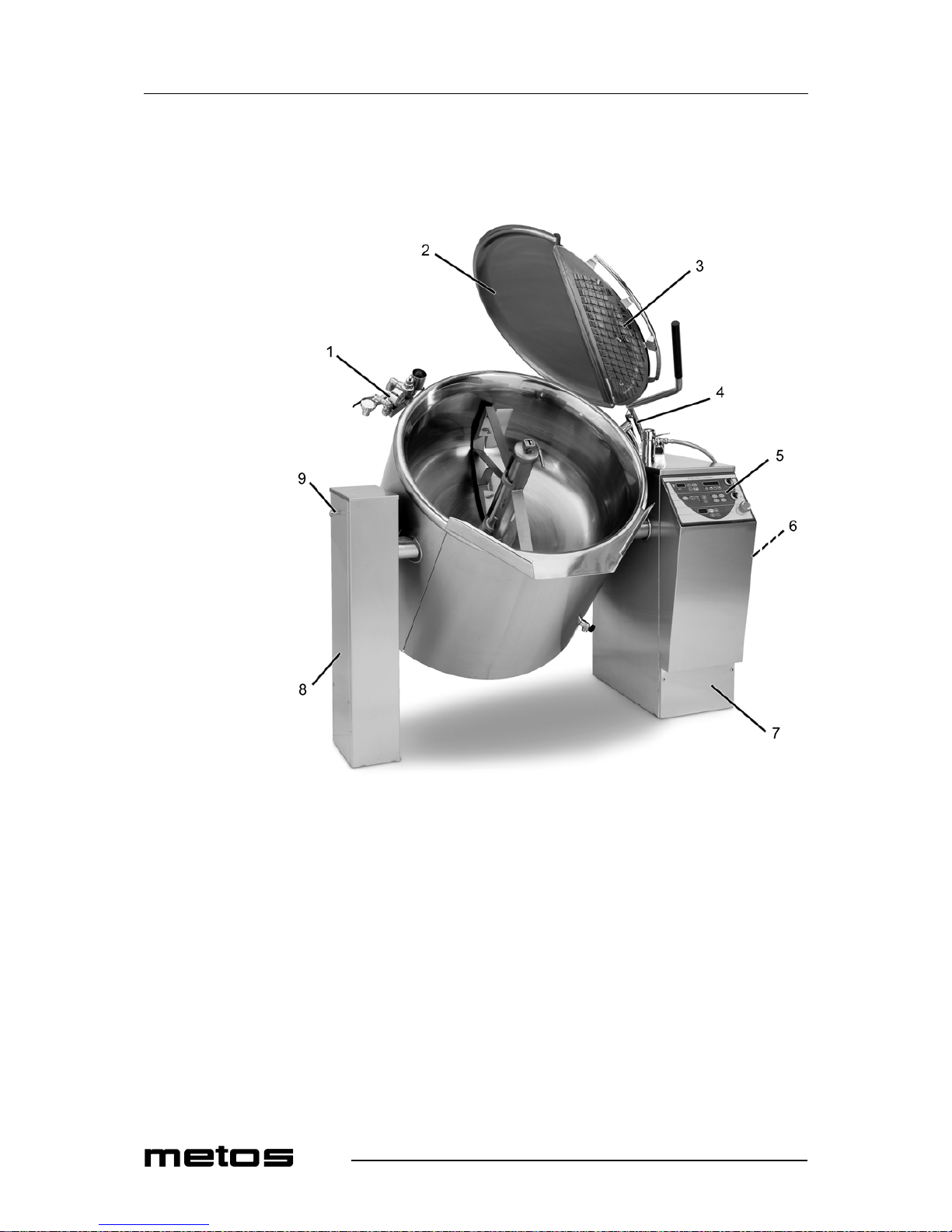
3.2 Construction and control panel
The main features of the Culino kettle are described in the following pictures.
1. safety block
2. safety lid
3. safety grid for opening
4. lid hinge
5. control panel
6. cleaning hose
7. control pillar
8. support pillar
9. peg for hanging tools

15.6.2012 Rev. 1.7
Functional description
7
1. fixing screw of lid
2. cover for lid opening
1. safety grid for lid opening
2.
safety
switch
1.
one-arm faucet for cleaning hose
2.
spout for kettle filling
1.
emptying valve of kettle jacket

15.6.2012 Rev. 1.7
Functional description
8
The control panel and its functions are described in the following picture. Please note that
the function buttons for mixing, timer and automatic water filling are not in the control
panel if the kettle is not equipped with these options.
Functions of the Culino kettle
1. digital temperature display
2. temperature increasing button
3. temperature decreasing button
4. tilting button
5. tilting button to upright position
6. kettle on-off switch with indicator light
7. low water level indicator light (on electrically heated models only)
8. emergency-stop button
Timer functions
9. starting time programming button
10. cooking time programming button
11. digital timer display
12. time increasing button
13. time decreasing button
Mixer functions
14. mixer on-off switch with indicator light
15. start/stop-button
16. function light
17. auto-reverse button
18. mixing speed indicator lights
19. mixing speed increasing button
20. mixing speed decreasing button
21. indicator lights of pre-set programs
22. buttons of pre-set programs 1-4
Water filling system
23. 3-digit display
24. automatic water filling
25. manual water filling + reset
26. setting is decreasing
27. setting is increasing

15.6.2012 Rev. 1.7
Operating instructions
9
4. Operating instructions
4.1 Before use
Check the following points before using the kettle.
4.1.1 After the installation
Check that
• the kettle has been installed horizontally according to the installation instructions
• all connections (electricity, water and steam) are tight and correctly made.
4.1.2 Before the first use
• Clean the kettle thoroughly with warm detergent solution and remove the dust and
dirt with a cloth. Dry all surfaces after cleaning.
4.1.3 Daily
Check that
• the kettle is in its upright and horizontal position. The kettle does not heat if it is
tilted.
• the scrapers are correctly attached to the mixing tool. See "Positioning the mixing
tool
and scraper".
•
the mixing tool has been locked in its place: locking part (one end of the handle)
in the groove of the mixer axle, with the handle turned in a horizontal position. Secure fixing by trying to lift the tool out of the kettle by the upper bl
ade.
4.1.4 Quarterly
Check that the safety valve functions correctly:
1. Do the checking when the kettle is empty.
2. Switch the kettle on by turning the green kettle on-off switch to the ON position.
3. Set the cooking temperature to 120°C by pressing the temperature increasing but-
ton marked with "+".
4. When the display indicates 120°C, check that the pressure gauge shows 1,0 bar
pressure.

15.6.2012 Rev. 1.7
Operating instructions
10
5. Keep the temperature increasing and decreasing buttons ("+" button and "–" but-
ton) simultaneously pressed until the display indicates 125°C and 1,5 bar. The
safety valve should now open and release steam. Release both temperature buttons.
NOTE! On kettles with jacket cooling C2 the test button on the right hand side of
the control pillar has to be kept pressed together with the + and the - buttons
1. kettle on-off switch
2. temperature adjustment buttons
1. Test button
If the safety
valve does not open at the latest when the pressure gauge indicates 2 bar, the
power must immediately be switched off using the green on-off switch. Contact qualified service personnel. It is not allowed to use the unit before it has been checked.
The safety valve function must be checked at least four times per year. The manufacturer
is not responsible for damag e caused by n eglecting the regular checking of the safety
valve.

15.6.2012 Rev. 1.7
Operating instructions
11
4.1.5 Yearly
• It is advisable to have the unit checked once a year by qualified personnel. Preven-
tive checking is the best guarantee for operational reliability and saves breakdown
costs.
Fill out the form “Notes on service work” with information on service work which has
been done according to the instructions. Maintenance work ensures the safe and reliable
function of the kettle.
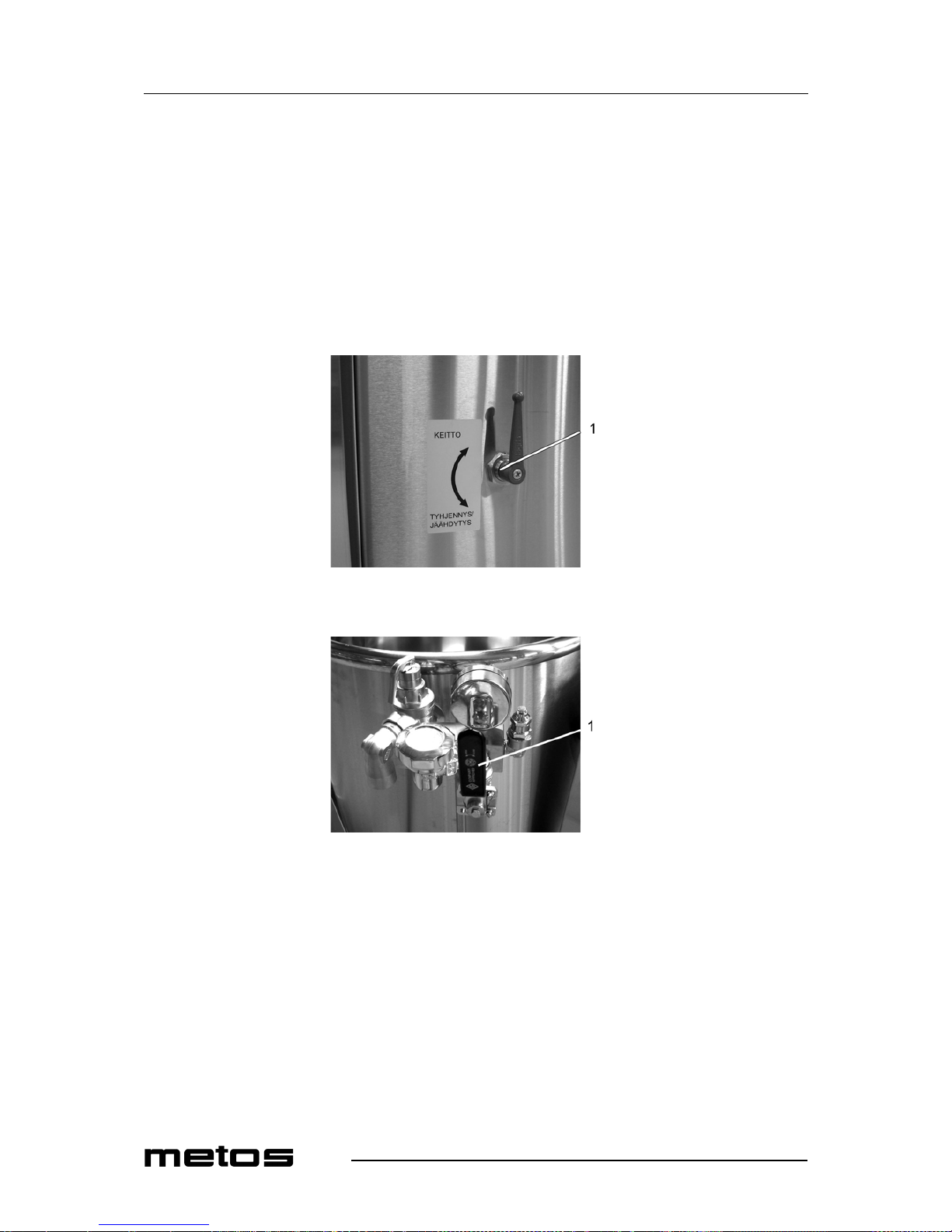
4.1.6 Emptying of surplus condensate water
It is not allowed to open the emptying valve of the kettle jacket, if the temperature of the
steam jacket of the kettle is over +100°C. Watch out for releasing hot steam and water
when you open the above mentioned valve.
1.
emptying valve of kettle jacket
• Check that the kettle is in its upright position.
• Open the emptying valve by turning the handle downwards.
The kettle does not heat, if there is a lot of surplus condensate water or undrained cooling
water in the kettle jacket.
4.1.7 Total emptying of the kettle jacket
It is not allowed to open the emptying valve of the kettle jacket, if the temperature of the
steam jacket of the kettle is over +100°C. Watch out for releasing hot steam and water
when you open the above mentioned valve.
1. Open the emptying valve.
2. Tilt the kettle approximately 45°.
3. When water stops to flow out, tilt the kettle slightly forwards and backwards until
water no longer flows out.
4. Return the kettle to the cooking position.

15.6.2012 Rev. 1.7
Operating instructions
12
4.2 Operation
4.2.1 Cooking
The cooking temperature can be set with one degree accuracy between 0...120°C. The
temperature of the steam jacket of the kettle is always at least the same as the room temperature or the same as the temperature of the cooling agent, if the kettle is equipped with
a cooling attachment (option).
Starting to cook
• Check that the emergency-stop button is not pressed down. The emergency-stop
button can be released by turning it clockwise until it jumps up.
• Switch on the power by turning the green on-off switch to the right (the green sig-
nal lamp illuminates).
•
Press once either one of the temperature adjustment buttons.
• Press again the temperature button and set the temperature. When you keep the
temperature button pressed down, the temperature changes with one degree at a
time.
1. on-off switch
2. digital temperature display
3. low water level indicator light (on electrically heated models only)
4. temperature increasing button
5. temperature decreasing button
If the set temperature is higher than the actual temperature, the kettle starts to heat immediately.
Temperature display
The digital temperature display always indicates the temperature of the kettle. When you
want to measure the temperature of the food, use a separate thermometer.
Mixing makes the temperature differences in different parts of the food more even.
Checking the set temperature
Press either one of the temperature adjustment buttons. The digital display indicates for
five seconds the set temperature, after which the display switches back to the actual temperature of the kettle.

15.6.2012 Rev. 1.7
Operating instructions
13
Changing the set temperature
1. Press once either one of the temperature adjustment buttons. The digital display in-
dicates the set temperature (for five seconds).
2. Choose the temperature by pressing the temperature increasing or decreasing but-
ton. When you keep the temperature button pressed down, the temperature changes
with one degree at a time. Release the button when the digital display indicates the
desired set temperature. After approximately five seconds the disp lay switches
back to the actual temperature of the kettle.
Stopping the cooking
Turn the green on-off switch lightly to the left. The green indicator light goes off and the
kettle stops cooking.
The kettle tilts only if the kettle is switched on. Since the kettle chills slowly, you can stop
cooking and begin the simmering by decreasing the set temperature to e.g. +70°C.
The cooking will automatically stop when the kettle is tilted. The cooking goes on automatically when the kettle is returned to an upright position.
4.2.2 Tilting the kettle
Open the safety lid of the kettle before tilting and ensure that there is enough space for
tilting behind the kettle.
1. The kettle is emptied by pressing the tilting button
2. The kettle goes back to its upright position by pressing the upright position
button.
For security reasons, th e kettle tilts only when the tilting button is kept continuously
pressed.

15.6.2012 Rev. 1.7
Operating instructions
14
4.2.3 Filling water into the kettle (Culino 40-400)
Depending on the kettle version, the water supply fittings can consist of
1. a faucet (1)
2. a faucet (1) + a two-arm faucet with spray gun (2)
3. a spout for automatic water filling (3)
4. a spout for automatic water filling (3) + one-arm faucet with spray gun (4)
Use only cold tap water for cooking.
4.2.4 Mixer operation
The mixer operates only when the safety lid and the safety grid of the lid opening are attached and closed.
If one of the safety features has interrupted the operation of the mixer, a green indicator
light in the control panel blinks to indicate the interruption.
When the cause of the interruption has been removed, the preset program can be continued from where it was interrupted.
Positioning the mixing tool and scrapers
Attach the scrapers by placing the pins on the mixing tool into the holes on the scrapers.
After that turn the scraper into place by lif ting the scraper’s lower part. Finally pull the
scraper forward. The bevel (1) will on the lower scraper point upwards and on the side
scraper away from the mixer axle.

15.6.2012 Rev. 1.7
Operating instructions
15
The mixing tool is equipped with 1-5 scrapers, depending on the size of the tool.
Scrapers are not needed when preparing la rge quantities of mashed potatoes or when
kneading dough. Use scrapers in all other cooking modes to increase the efficiency of heat
transfer and to help the cleaning of the kettle.
It is easiest to attach the mixing tool to the mixer axle when the kettle is in a tilted position.
Push the ring on the mixing tool into the kettle's mixer axle and fit the mixing tool in place,
while the lifting handle is straight so that the locking device of the lifting handle sets in
the groove at the upper end of the mixer axle.
Scraper 40 60 80 100 150 200 300 400
Scraper A2 -1121212
Scraper B2 (bottom) - - - 1 1 1 1 1
Scraper C2 (bottom) 1 1 - - 1 1 2 2

15.6.2012 Rev. 1.7
Operating instructions
16
Then turn the handle aside.
Make sure that the mixing tool is locked in its place by trying to lift/pull it out of its place
by pulling at the mixer blade, for example.

15.6.2012 Rev. 1.7
Operating instructions
17
Safety lid and safety grid for lid opening
It is absolutely forbidden to use the mixer without the safety lid and the safety grid for lid
opening (working safety regulations).
The safety lid and the safety grid for lid opening are to be attached as follows:
1. When the safety lid is closed, put the ends of the hinges into the oblong holes on
the front edge of the safety lid.
1. hinge
2. safety grid for lid opening
2. Turn the safety grid down to its place, the safety switch enables the operation of
the mixer.
3. It is possible to put a stainless steel cover over the safety grid to decrease the steam
outflow when cooking.
1. cover for lid opening
Opening the safety grid:
1. Turn the safety grid to an upright position, the slots in the hinges keep it in an open
position. If the mixer is mixing, it will stop.

15.6.2012 Rev. 1.7
Operating instructions
18
Closing the safety grid:
1. Lift the safety grid lightly upwards and turn it after that down over the kettle.
2. If necessary, switch the mixer on according to the instructions given below.
Opening of the whole safety lid:
1. Switch off the mixer if it is on.
2. Lift the safety lid by the black part of the lifting arm to its utmost position. The gas
spring will keep it in the open position.
3. If the cover for the lid opening was on, it remains on the safety grid because of a
locking peg.
1. locking peg
Manual operation of the mixer
1. Ensure that the emergency-stop button is not pressed down. If pressed, release it
by turning it clockwise until it jumps up.
2. Switch on the power by turning the green mixer on-off switch lightly to the right
(the green indicator light illuminates).
3. Start the m ixer by pressing the start-stop button. The mixer starts at the l owest
speed.
4. Choose the desired mixing speed.
5. If desired, switch on the auto-reverse mode by pressing the auto-reverse button.
1. start/stop button
2. auto-reverse button
3. mixing speed indicator light
4. mixing speed increasing button
5. mixing speed decreasing button
6. mixer on-off switch

15.6.2012 Rev. 1.7
Operating instructions
19
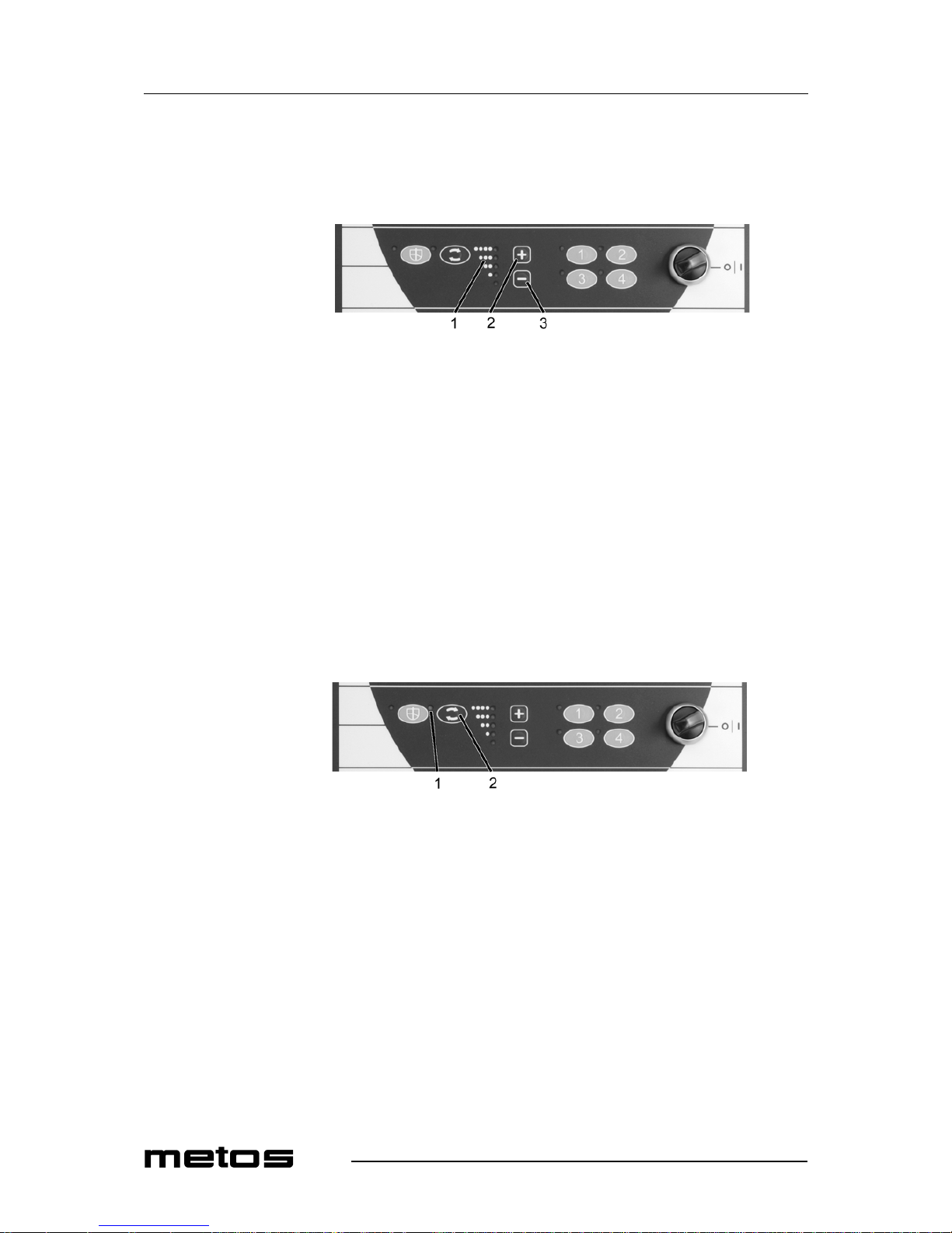
Operation of the pre-set mixing programs
The automatic mixing programs are pre-set and can not be changed. The programs will
start immediately when the desired button is pressed. You can at any time directly switch
over from one program to another program.
1. indicator light of pre-set mixing program
2. buttons of pre-set programs
Interrupting and continuing of mixing programs
The pre-set program can be interrupted by opening the safety grid or the safety lid. If the
mixing program has been interrupted, the green indicator light of the interrupted program
will begin to blink. When the safety grid and the safety lid are closed, you can continue
the program from the point of interruption by pressing the same button.
Stopping the mixing and pre-set programs
The mixing and the pre-set programs can be interrupted alternatively by pressing the
• start/stop button (1)
• emergency-stop button (2)
• or by turning the mixer on-off switch (3) to the 0 position.
1. start/stop button
2. emergency-stop button
3. mixer on-off switch
4. buttons of pre-set programs
The mixing program can also be stopped by pressing once again the pre-set mixing program button while the program is running.
15.6.2012 Rev. 1.7
Operating instructions
20
Mixing speeds
The five indicator lights to the left of the buttons of pre-set programs indicate the pre-set
mixing speeds.
1. mixing speed indicator light
2. mixing speed increasing button
3. mixing speed decreasing button
The corresponding mixing speeds are:
Auto-reverse function
In spite of the speed selected, always 10 seconds clockwise and 5 seconds counterclockwise.
1. on-off light for auto-reverse
2. auto-reverse button
1 = 20 rpm
2 = 40 rpm
3 = 60 rpm
4 = 80 rpm
5 = 110 rpm

15.6.2012 Rev. 1.7
Operating instructions
21
Description of pre-set mixing programs
The purpose of use, different phases of the program and the mixing speeds are shown in
the following table.
Buzzer signal (not program 1):
• Between the program phases, a buzzer signal of three sequential periodical sounds
will be heard for approximately 10 seconds.
• At the end of the program, a single periodical buzzer sound will be heard for approximately 10 seconds.
Maximum amount of mixing
The turning force and mixing features of the mixer are measured to mix most food ingredients. There might although be food ingredients with a consistency that requires decreasing the kettle contents or adding liquid to improve the mixing result. The turning force is
best in the range 20-60 rpm (1-3).
No.
phase
Mode Duration Speed Rev/direction Other Buzzer Final
buzzer
1 Soup 20 rpm 1,5 ccw/1,5 cw pause 2 min no no
2.1 Universal program 7 min 80 rpm 1 cw/1 ccw yes
2.2 10 min 40 rpm 5 cw/2 ccw yes
2.3 30 min 20 rpm 5 cw/2 ccw yes
3.1 Mashed potatoes 60 rpm 1 cw/1 ccw 3 times no
3.2 1 min 60 rpm 10 cw/2 ccw yes
3.3 5 min 80 rpm 10 cw/2 ccw yes
3.4 4 min 60 rpm 8 cw/2 ccw yes
4.1 Dessert 2 min 80 rpm 6 cw/2 ccw yes
4.2 15 min 40 rpm 5 cw/5 ccw yes
4.3 20 min 80 rpm 5 cw/2 ccw yes

15.6.2012 Rev. 1.7
Operating instructions
22
4.2.5 Manual cooling C1 (optional)
The cooling system is based on cold tap water which is circulating inside the steam jacket.
Mixing and use of scrapers makes chilling more effective. The needed chilling time depends on the quantity of product, the temperature at the beginning and at the end of cooling, the flow and temperature of chilling water as well as mixing.
Starting the cooling
1. Set the temperature to 0°C.
2. Close the one-arm faucet by pressing the handle down.
3. Remove the spray gun from the cleaning hose by pulling the connector away from
the spray gun. Connect the cleaning hose to the emptying valve outlet which is on
the lower right front side of the kettle.
1. emptying valve outlet
2. cleaning hose
4. Open the emptying valve by turning the handle downwards.
1. emptying valve
5. Turn the 3-way valve in the safety block to the cooling position (downwards).

15.6.2012 Rev. 1.7
Operating instructions
23
1. 3-way valve in cooling
position
6.
Open the water tap by turning the handle of the one-arm faucet for the cleaning
hose to the right and raise upwards.
The digital display indicates that the cooling has started.
Stopping the cooling
1. Close the one-arm faucet by pressing the handle down.
2. Remove the cleaning hose from the emptying valve.
3. Turn the 3-way valve to the cooking position (upwards).
1. 3-way valve in cooking
p
osition
4. Let the extra water run out of the steam jacket through the emptying valve. Close
the emptying valve when the kettle is in an upright position and water stops flowing out.
It takes a few minutes to let the extra water run out of the steam jacket. If you first want
to empty the kettle, close the emptying valve before tilting.
The kettle will not warm up properly, if cooling water is not completely drained from the
kettle jacket.

15.6.2012 Rev. 1.7
Operating instructions
24
4.2.6 Operation of the timer (optional)
The timer allows you to start cooking at th e required time and set the cooking duration.
After the set cooking time has elapsed, the temperature of the kettle is automatically set
to +70°C. The holding temperature is on un til the kettle is switched off with the on-off
switch. The digital display shows the actual time if the timer is not used, but the kettle has
been switched on.
It is not possible to use the kettle if the timer is activated until the set time is reached or
the timer has been switched off. When the timer is activated, a green light in the top left
corner of the button is illuminated.
Setting and changing the time
1. Press the time increasing "+" and time decreasing "–" buttons at the same time for
about two seconds until the hour display begins to blink.
1. digital timer display
2. starting time programming button
3. time decreasing button
4. time increasing button
2. Set the right hour with the "+" and "–" buttons.
3. Press once the starting time button, the minutes start to blink on the timer display.
4. Set the right minutes with the "+" and "–" buttons.
5. Press once the starting time button, the set time will be memorized and the timer
starts counting.
Setting and changing the starting time
Set the required cooking temperature first.
• Press the starting time button for two seconds until the hours start to blink on the
display.
• Set the starting time (hour) with the "+" and "–" buttons.
• Press once the starting time button, the minutes blink on the display.
• Set the starting time (minute) with the "+" and "–" buttons.
• Press once the starting time button. The starting time will be memorized.
When you use the timer, ensure that the time on the display and the set starting time are
right and you have activated the starting time program (the green is light illuminated).
Checking the set starting time
Press once the "–" button. The display shows the set starting time. After a few seconds the
timer display reverts to the actual time.

15.6.2012 Rev. 1.7
Operating instructions
25
Setting and changing the cooking time duration
1. Press the cooking time programming button for two seconds, the h ours start to
blink on the display.
1. digital timer display
2. cooking time programming button
3. time decreasing button
4. time increasing button
2. Set the hours with the "+" and "–" buttons.
3. Press once the cooking time programming button, the minutes start to blink on the
display.
4. Set the minutes with the "+" and "–" buttons.
5. Press once the starting time button. The starting time will be memorized.
When the set cooking temperature is reached, the pre-set cooking time starts to elapse and
the display begins to show the cooking time which is still left.
When the set cooking time is reached, the temperature is automatically set to + 70°C and
the display shows “Hold”.
When you use the timer, ensure that the time on the display and the set starting and cooking times are right and you have activated the starting time program and the cooking time
program (green indicator light illuminated).
Checking the duration of the cooking time
Press once the "+" button. The display shows the pre-set cooking time in hours and minutes. After a few seconds the display reverts automatically to the actual time.

15.6.2012 Rev. 1.7
Operating instructions
26
4.2.7 Automatic water filling (option)
A desired amount of cold water can be dispensed to the kettle by the automatic water dispenser in the following way:
• water filling is manually kept on until the desired amount of litres appears on the
display of the control unit
or
• automatic water running stops when the amount of litres set beforehand in the control unit are achieved.
1. 3-digit display
2. automatic flow on/off
3. manual flow + reset
4. setting is increasing
5. setting is decreasing
Basic mode
• The appliance is on when the kettle on-off switch is on; 0 appears in the last digit’s
position.
• Decimal point is illuminating.
• The set amount of filling has been achieved. The values are 0.
• If the function of the appliance is interrupted by switching off the control voltage,
the reswitching of voltage will always set it to this basic mode.
Manual water filling
• Filling starts when the MAN/RESET button is pushed and held down for the duration of filling.
• The display is updated with an accuracy of one litre as long as the button is held
down.
• The achieved value in litres is shown on the display for 10 seconds after stopping
the filling. Then 0 appears on the display.
• If you want to continue filling within the mentioned time, the value on the display
will continue increasing.
Automatic filling of water
• Set the desired amount by pushing the “+” button (4). The set value appears on the
display.
• The value can be decreased by using the “–” button (5).
•
The value is shown on the display for 10 seconds, whereafter the set value will be 0.
• Start the filling by briefly pushing the automatic flow on/off button while the set
value is illuminating on the display.
• After starting the filling function, the display will cumulatively show the amount
of water filled (in litres) and the flow stops automatically when the set value has
been achieved. The set value is reset to zero.

15.6.2012 Rev. 1.7
Operating instructions
27
• The amount of water flown will stay on the display and the appliance reverts to the
basic mode by pushing either the automatic flow on/off or MAN/RESET button.
Interrupting the automatic filling of water
• The function is interrupted by pushing the automatic flow on/off button.
• The achieved value stays on the display and the decimal point is blinking.
• The set value is saved in the memory.
• In the interrupted mode, the setting can be changed using the “+”/”–” buttons.
• The water dispenser reverts to the basic mode by pushing either the automatic flow
on/off or MAN/RESET button.
• If the function is interrupted by pushing the emergency-stop button, the appliance
reverts to the basic mode and the settings must be done again.
Continuing the automatic water filling after interruption
• The filling will continue from the achieved value up to the set value by pushing the
automatic flow on/off button.
• After this the decimal point will illuminate continuously.
Error in automatic water filling
• If there is an error in flow measurement or if water does not flow, the value on the
display blinks.
• The water dispenser reverts to the basic mode by pushing either the automatic flow
on/off or MAN/RESET button.
Settings
Maximum filling amount
• The maximum filling amount has been set in the factory according to the kettle
size.
• The setting is changed by first pushing the “–” button and immediately after that
the “+” button for 5 seconds, after which the display value starts to blink. The new
setting value according to the kettle size is set using the “+”/”–” buttons. The maximum set value is 400 litres.
• The set value is saved if the setting is not changed in 5 seconds.
Calibration of flow measurement
• Basic calibration has always been done in the factory, so normally it need not be
done again.
• If, however, calibration is needed, first push the MAN/RESET button and immediately after that the “–” button for 5 seconds, whereafter the value 855 starts to
blink on the display.
• To decrease the flow, push the “–” button, so the value decreases. To increase the
flow, push t he “+” button, so the val ue increases. The amount of flow must be
checked by pouring 5 litres of water into a measuring vessel.
• The set value is saved if the value is not changed within 5 seconds.

15.6.2012 Rev. 1.7
Operating instructions
28
4.3 After use
4.3.1 Cleaning the kettle
Use of a high pressure hose for clean
ing of the kettle is forbidden.
Cleaning the panel overlay with steam is prohibited!
Note that it is not allowed to spray the air inlets or the control panel with water when
cleaning the kettle with a spray gun.
Always clean the unit carefully immediately after use, considering the hygienic aspects.
Cleaning is more easy to do and needs less water in this way.
Recommended tools for cleaning:
• special cleaning detergents for stainless steel
• nylon brush
• soft rubbing sponge (white)
• other materials meant for stainless steel which do not scratch the surfaces of the
kettle
Tools not allowed for cleaning:
• high pressure hose
• all metallic tools
• rough rubbing sponge (green)
• steel wool
• abrasive detergents
Cleaning procedure:
1. Chill the kettle with cold water
2. Scrape the dirt with a plastic scraper.
3. Spray detergent in the kettle, brush and wash clean with a water hose
4. Dry the kettle
Clean the outer parts of the kettle using running water only if necessary. Do not use water
more than is necessary. Cleaning with a damp cloth will often be enough.
All optional extras of the kettle such as strainer plates, mixing tools and scrapers, cooking
baskets and parts of the safety lid can be washed in a dishwasher.
The dosing and impact time instructions for cleaning detergents must be followed - e.g.
exceeding the impact time for foam cleaning detergents in combination with salt residues
has been observed to cause severe spot corrosion even on stainless steel.
The manufacturer does not take any responsibility for possible damage caused by not following the instructions above.

15.6.2012 Rev. 1.7
Operating instructions
29
Using the different parts of the safety lid
The safety lid consists of the following parts: the solid lid, the safety grid for the lid opening and the cover for the lid opening. All these parts can be washed in a dishwasher.
1.
solid lid
2.
safety grid for lid opening
1.
cover for lid opening
Taking the safety lid apart
1. Close the lid.
2. Remove the cover of the safety grid by raising it upwards.
3. Remove the safety grid by raising it first to an upright position (open position) and
then simultaneously raising and pulling it towards yourself.
4. Remove the solid lid by pulling the interlock lock, at the same time holding the
lid’s lifting handle with the other ha
nd.

15.6.2012 Rev. 1.7
Operating instructions
30
Fitting the parts of the lid
1. Put the solid lid over the kettle and put the lifting arm down so that the guide cone
meets the hole on the arm. Also make sure that the smaller guide cone meets the
counter hole on the arm. Ensure that the lock pin sets in its lowest position.
2. Position the safety grid by putting the ends of the hinges into the oblong holes
which are on t he front edge of the safety lid and then lowering the grid down on
the kettle.
4.3.2 Treatment of stainless steel
The following table contains the most typical problems encountered in the treatment of
stainless steel and their solutions.
Note that some substances mentioned in the table can damage the stainless steel surface
if they are used too long or th ey are too strong. The refore, the instructions given in the
schedule must be strictly followed.
Effect Cause How to avoid/remove
Little white spots on the
bottom of the kettle
Salt has been added to
cold water.
Add salt always into boiling water or when the food is ready.
Clean with acetic solution (0,5 dl vinegar/1 l water), heat appr.
1/2 hours, brush and rinse.
Grey-white blotches and
spots, calcareous deposits
Hard water containing
calcium and magnesium
salts.
Clean with acetic solution (1 dl vinegar/1 l water), heat approx.
1/2 hours, brush and rinse.
Brown spots Dirt from food ingredi-
ents, steel particles coming from outside.
Clean with acetic or alkaline solution according to the cause.
"Rainbow colours" Sudden temperature
change.
Totally harmless, disappears in use.
Tightly stuck food Too high cooking temper-
ature.
Soak water in the kettle and cook diluted alkaline solution according to instructions given with the detergent. Reduce cooking temperature.
Blue coating Substances containing
carbohydrate or old coffee
and tea spots.
Sometimes hard to remove. Soak water in the kettle and cook
diluted alkaline solution according to instructions given with
the detergent.
Firmly adhered label or
sellotape
Adhesive from labels or
sellotape
Rub the adhesive with a cloth dipped in cooking oil. Do not
scratch the surface.

15.6.2012 Rev. 1.7
Operating instructions
31
4.3.3 Notes on service work
Kettle/kettle group___________________________ Date of installation_________________________________
Checking the safety valve four times per year:
Yearly maintenance:
Descaling:
Date Checked by Notes Date Checked by Notes
Date Checked by Notes Date Checked by Notes
Date Checked by Notes Date Checked by Notes

15.6.2012 Rev. 1.7
Installation
32
5. Installation
5.1 Before installation
Please observe the following instructions and warnings when planning and carrying out
the transport and installation of the kettle in order to reduce the risk of damage, failure or
injury. This applies to forwarders, transport personnel, installation professionals and endusers alike. Not following the instructions might cause damage to the units and personnel.
5.1.1 Transport and reception
The unit must be transported in its own package to avoid transport damage. It is forbidden
to load any heavy packages on the unit during transport and storage.
The unit is not stable until bolted down to the floor. For this reason it is imperative not to
operate or tilt the kettle until it is bolted down according to the installation instructions.
When the kett le is removed from its transport pallet, it must be supported to prevent it
from falling before it is fixed to the floor. If the kettle falls down, this may cause damage
to the unit and put personnel at risk.
The consignee of the kettle must check the unit immediately after transport and if any
damage is detected, it must be noted on the bill of freight. If this is neglected, all transport
damage detected later on (except those covered by normal product guarantee), will be repaired at the customer’s cost.
5.1.2 Storage
The unit must be stored in a dry place where the temperature is between + 0° and 40°C.
The unit must remain in its own package during storage.
If the unit is stored on a con struction site, special care must be taken not to damage the
unit when carrying out other construction work.
• Protect the outer surfaces of the unit from scratches and knocks.
• Protect the unit from construction site dust.
• Protect the unit from welding, grinding and abrasive cutting wheel sparks. These
might later cause rust spots on the stainless steel surfaces of the unit.

15.6.2012 Rev. 1.7
Installation
33
5.1.3 Facilities
The kettle can be used in a normal, air-conditioned professional kitchen. The room temperature of the installation place must not exceed +40°C and the relative humidity must
be less than 80% (condensation on surfaces not allowed to occur). If the temperature of
the facility in winter conditions is below 0°C, the steam generator of the kettle must be
drained and the kettle must be emptied to avoid damage caused by freezing. The kettle's
pipes and solenoid valve bodies must be emptied at the same time.
5.1.4 Unpacking the unit
The kettle is transported in its own package as near the installation place as possible before final unpacking. Remove the plastic foil wrapped round the kettle after the installation just before the first use of the kettle.When unpacking all packing material must be
sorted and disposed of according to local recycling regulations.
5.1.5 Industrial safety during installation
Beware of sharp edges of sheet constructions in the kettle pillars when installing the unit.
Do not switch the power on, if the unit installation area is wet or moist.
5.2 Installation
Check before the installation from the installation drawing that there is enough space behind the kettle for tilting. Check also the location of the floor drain.
The kettle can be installed in the following two ways:
• on subsurface installation frames, frames cast into the floor
• on surface installation frames, frames fixed between the kettle and the floor
Remove the front panels of the control pillar and support pillar when installing. It is recommended to put wooden slats below the kettle axles when raising the unit during the installation to avoid possible falling of the kettle. If you are installing a kettle group, first
separate the kettles. Begin the instal lation with the left-hand kettle and do not forget to
support the right-hand kettle after removal from the left-hand temporary support.

15.6.2012 Rev. 1.7
Installation
34
5.2.1 Installation on subsurface frames cast into the floor
The optional subsurface installation frame is to be correctly positioned before casting. The
frame should be installed in a horizontal position and fixed so that it will not move during
the casting. The top of the installation frame must be approx. 30 mm above the finished
floor surface. The junction between the floor and the frame is to be covered with flooring
material up to the level of the installation frame as shown in the picture below.
1. Installation frame
2. Concrete casting
3. Finished floor surface
4. Silicone mastic
5. Acrylic filler
Place the kettle on the installation frame and ad just to a horizontal position with the a djusting bolts which are in the corners of the pillars. When the kettle is in a horizontal position it must be fi xed by screwing the nuts on the t wo fixing bolts of the installation
frame. Tighten the adjusting nuts carefully. Do not seal the space between the kettle pillars
and installation frame as there must be enough change of air.
4
3
5
1
2

15.6.2012 Rev. 1.7
Installation
35
5.2.2 Installation on surface installation frames
The optional installation frame is to be installed according to the installation drawing. If
the floor is not even, it might be necessary to straighten the installation frame to a position
nearer to the horizontal by putting some stainless steel spacers between the frame and the
floor, so that the adjustment range of the pillar is sufficient.
The junction between the installation frame and the floor is sealed with silicone or similar.
1. Surface frame
2. Concrete casting
3. Fixing bolt for surface frame
4. Finished floor surface
5. Silicone mastic
6. Acrylic filler
Fixing bolts of the surface in stallation must be chosen acco rding to the floor material.
Recommended type is a UKA 12x200 chemical bolt, which is suitable for different floor
materials. Alternatively expansion-shell bolts or equivalent can be used.
Place the kettle on the surface installation frame and adjust to a horizontal position with
4 adjusting bolts which are in the corners of the pillars. When the kettle is in a horizontal
position it will be fixed by screwing the nuts on the two fixing bolts of the surface installation frame. Tighten the fixing nuts careful ly. Do not seal the space between the kettle
pillars and surface installation frames, as there must be enough change of air.
5.3 Electrical and water connections
The electrical and water connections for each kettle (single or gro up) are made through
the floor to the right-hand kettle pillar according to the inst allation drawing. The water
pipes must not rise more than 100 mm from the floor surface.
1
5
4
6
3
2

15.6.2012 Rev. 1.7
Installation
36
5.3.1 Electrical connection
Connections are to be done according to the installation drawing and the electric diagram.
The kettle is equipped with a decoupling switch, which separates the kettle totally from
the electrical network.
5.3.2 Water connection
The water connection is to be done according to the installation drawing. Connections to
the water tap are to be fitted with one-way and shut-off valves (not included in delivery).
The cold water connection is of size Ø 15 mm (G 1/2”) and the warm water connection of
size Ø 10 mm (G 3/8”).
5.3.3 Steam and condensate connections
The steam and condensate connections of the Culino combi-kettle must be carried out by
a person with professional competence in the field. Improper connections and piping may
severely impact the correct function of the kettle.
The location of the steam and condensate connection points appears from the installation
drawing.
The maximum steam pressure in the kettle is 1 bar. The steam supply line must be fitted
with a one-way valve, a shut-off valve, a filter, a pressure reduction valve and a safety
valve set at 1,5 bar.
The condensate pipe must be on the same floor as the kettle or go to the floor below. Leading the condensate pipe to the floor above the kettle is not allowed, as it creates a water
trap that prevents normal function of the kettle.
The condensate pipe must be free from pressure created by other appliances.
5.4 Ventilation
The heat and steam load of the kettle must be taken into account in the kitchen's ventilation plan. A ventilation hood must be installed above the kettle, because plenty of steam
is released when the kettle lid is opened. When dim ensioning the ventilation hood, the
space requirement for opening the lid must be taken into account (see installation drawing).
5.5 Other installations
In case the combi-kettle being installed is provided with a self-control option (HACCP),
and it is taken into use, the data cabling and the installation of the program must be carried
out according to separate instructions.

15.6.2012 Rev. 1.7
Installation
37
5.6 Adjusting the tilting
Ensure that the kettle pillars are in a horizontal position. If not, adjust according to the installation instructions. Ensure that the rim of the kettle also is horizontal. If not, adjust the
tilting as follows.
The adjustment is done from the lower mounting point of the tilting motor as follows:
1. Open the locking screw
2. Open the locking nut.
Culino Combi 40-200 l Culino Combi 300 l, 400 l
1. locking screw
2. adjusting screw
3. Adjust with the adjusting screw which is inside the U-profile.
4. Lock with the screw and tighten with the nut.
5. Finally check that the roller plunger of the tilting limit switch trips when the kettle
is in an upright position.
1. roller plunger
2. tilting limit switch - cooking position
3. tilting limit switch - extreme position
15.6.2012 Rev. 1.7
Installation
38
5.7 Testing the kettle
Do the following measurements and checks before taking the kettle into use.
5.7.1 Cooking mode
Before the kettle is switched on, the kettle jacket emptying valve must be closed.
Do the following:
• Check that the kettle is in its upright position.
1. emptying valve cooking
position
• If the kettle is equipped with a cooling option, also check that the outlet valve on
the safety device block is in cooking position (upwards).
1. 3-way valve in cooking
position
5.7.2 Checking the safety valve
Do the following measurements in order to check the safety valve:
1. Do the checking when the kettle is empty.
2. Switch the kettle on by turning the green kettle on-off switch to the ON position.
3. Set the cooking temperature to 120°C by pressing the temperature increasing button marked with "+".
4. When the display indicates 120°C, check that the pressure gauge shows 1,0 bar
pressure.

15.6.2012 Rev. 1.7
Installation
39
5. Keep the temperature increasing and decreasing buttons ("+" button and "–" button) pressed at the same time until the display indicates 125°C and 1,5 bar. The
safety valve should now open and release steam. Release both temperature buttons
when the safety valve has opened.
NOTE! On kettles with jacket cooling C2 the test button on the right hand side of
the control pillar has to be kept pressed together with the + and the - buttons
1. kettle on-off switch
2. temperature adjustment buttons
1. Text button
If the safety v
alve does not open at the latest when the pressure gauge indicates 2 bar,
switch off the power using the green on-off switch and contact qualified service personnel. It is not allowed to use the unit before it has been checked.
The safety valve function must be checked at least four times per year. The manufacturer
will not take responsibility for damage caused by neglecting the regular checking of the
safety valve.
THE KETTLE IS NOW READY FOR USE!

15.6.2012 Rev. 1.7
Installation
40
5.8 Testing the mixer
The basic conditions for the perfect function of the mixer are that the kettle is correctly
fixed to the floor according to the installation instructions. The kettle and the kettle pillars
must also be in a horizontal position.
5.8.1 Checking the functions
Switch on the mixer by pressing the start/stop button. Check the following functions:
• the mixer is mixing at the lowest speed and only the lowest mixing speed indicator
light is illuminated
• the mixer rotates clockwise
• press the auto-reverse button
• ensure the auto-reverse function, approx. 10 seconds clockwise and approx. 5 sec-
onds counter clockwise
• try all rotat ing speeds by pressing the buttons to increase and decrease mixing
speed ("+" and "–" buttons)
• try all the four pre-set mixing programs
1. start/stop button
2. auto-reverse button
3. mixing speed indicator light
4. mixing speed increasing button
5. mixing speed decreasing button
6. buttons of pre-set programs
7. mixer on-off switch with indicator light
8. emergency-stop button
You can find the speeds and the pre-set programs in the section describing the mixer.
5.8.2 Checking the safety equipment
The mixer must stop when the safety grid or the lid itself is removed. If a pre-set program
was on, the indicator light near the program button blinks. The operation will continue,
when the lid and safety grid are replaced and the same program button is pressed again.
The mixer must stop immediately when the emergency-stop switch is activated. The
switch is released by turning it clockwise until it jumps to its upper position. After this the
mixer can be restarted.

15.6.2012 Rev. 1.7
Installation
41
5.9 Combination of machines
When the kettle is connected to a closed loop cooling system, a combination of machines
as specified in the machinery directive is created for which, at commissioning, a signed
declaration of conformity must be provided covering the combination of machines.
Machine 1
Kettle
Machine 2
Coolingsystem
Start signal
Error signal
Cooling circuit to kettle
Cooling circuit return
COMBINATION OF MACHINES

15.6.2012 Rev. 1.7
Troubleshooting
42
6. Troubleshooting
MALFUNCTION POSSIBLE CAUSE WHAT TO DO
The kettle does not heat The timer function is activated if the
kettle is equipped with a timer
Switch off the timer function according to
instructions
The emergency-stop switch is activat-edRelease the emergency-stop switch by turn-
ing it clockwise
The kettle on-off switch is not in the
ON position
Turn the on-off switch to the ON position
The fuses in the main fuse box are
blown/triggered
Change/excite the fuses
The kettle is not returned to an upright
position after tilting
Press the tilting button until the kettle is in a
totally horizontally position
Electric kettle: Not enough water in
the steam generator, water level indicator light illuminated
Check and add water to the steam generator
according to instructions
Steam kettle: Shut-off valve of the
steam input is closed
Open the valve
Other technical fault Contact qualified technical personnel
Heating of the kettle is slow Electric kettle: Too much water in the
steam generator
Check the water level of the steam generator
according to the instructions by opening the
water level valve.
Steam kettle: Condensate water gathered in the steam jacket has not been
emptied
Remove the condensate by opening the emptying valve which is in the steam jacket
Steam jacket of a kettle equipped with
a cooling system is full of cooling water which has not been emptied.
Remove the chilling water by opening the
water level valve (electric) or the emptying
valve for condensate (steam)
On a kettle equipped with a cooling
system air cannot flow out of the steam
jacket because the 3-way valve of the
cooling is in a wrong position.
Check that the handle of the 3-way valve in
the safety block is turned upwards
There is air in the steam jacket which
does flow out because the automatic
vacuum valve does not function.
If the air does not exit through the automatic
vacuum valve, contact qualified technical
personnel
One of the fuses in the main fuse box
is blown/triggered
Change/excite the fuse
Other technical fault Contact qualified technical personnel
The kettle does not tilt The emergency-stop switch is pressed
down
Release the emergency-stop switch by turning it clockwise
The kettle on-off switch is not in the
ON position
Turn the kettle on-off switch to the ON position
Other technical fault Contact qualified technical personnel

15.6.2012 Rev. 1.7
Troubleshooting
43
When you contact the service personnel, give the following information for the unit in
question:
• what is the type and model of the unit
• what is the serial number of the unit and the date the unit has been installed
• a short description of the fault
• what happened/was done immediately before the fault occurred
The mixer does not start The emergency-off switch is pressed
down
Release the emergency-stop switch by turning it clockwise
The mixer on-off switch is not in ON
position
Turn the mixer on-off switch to the ON position
The mixer start-stop button has not
been pressed
Start the mixer by pushing the start-stop button
The fuses in the main fuse box are
blown/triggered
Change/excite the fuses
Other technical fault Contact qualified technical personnel
The mixer does not start, indicator light on the control panel
blinks
The safety lid and the safety grid for
the lid opening are not on the kettle
Place the safety lid and safety grid for lid
opening on the kettle and restart
Other technical fault Contact qualified technical personnel
The mixer stops during mixing A pre-set program including stopping
of the mixer is in use
Check if a pre-set program is in use
The stuff to be mixed is too thick or
there is too much contents in the kettle
Make the contents of the kettle thinner or reduce the amount and restart.
Other technical fault Contact qualified technical personnel
The mixer stops during mixing,
indicator light on the control
panel blinks
The safety lid or the safety grid for the
lid opening has moved
Place the safety lid and safety grid for lid
opening on the kettle and restart
Other technical fault Contact qualified technical personnel

15.6.2012 Rev. 1.7
Troubleshooting
44

15.6.2012 Rev. 1.7
Technical specifications
45
8. Technical specifications
Installation drawing L00133 C3
Installation dimensions K02450 A3
Text L00134 B4
Steam supply recommendations 000030 A4

Installation drawing L00133 C3

Installation dimensions K02450 A3

Text L00134 B4

Steam supply recommendations 000030 A4

15.6.2012 Rev. 1.7
Technical specifications
Item Type Acces-
sory
Specification
Overall dimensions incl. support pillar WxDxH 40,60 1047x730x900/1080 mm
Overall dimensions incl. support pillar WxDxH 80,100 1154x785x900/1080 mm
Overall dimensions incl. support pillar WxDxH 150,200 1360x945x900/1080 mm
Overall dimensions incl. support pillar WxDxH 300 1560x1165x900/1080 mm
Overall dimensions incl. support pillar WxDxH 400 1560x1165x900/1230 mm
Support pillar dimensions LxDxH 150x250x865 mm
Distance needed behind the kettle 40 730 mm
Distance needed behind the kettle 60 820 mm
Distance needed behind the kettle 80,100 850 mm
Distance needed behind the kettle 150 910 mm
Distance needed behind the kettle 200 980 mm
Distance needed behind the kettle 300,400 1135 mm
Tilting height from outer shell to floor 40,60 455 mm
Tilting height from outer shell to floor 80,100 405 mm
Tilting height from outer shell to floor 150,200 420 mm
Tilting height from outer shell to floor 300 450 mm
Tilting height from outer shell to floor 400 440 mm
Maximum height of cover 40,60 1710 mm
Maximum height of cover 80,100 1800 mm
Maximum height of cover 150,200 1980 mm
Maximum height of cover 300 2100 mm
Maximum height of cover 400 2235 mm
Distance needed for service, left side 250 mm
Distance needed for service, right side 150 mm
Inner diameter 40, 60 472 mm
Inner diameter 80,100 545 mm
Inner diameter 150,200 744 mm
Inner diameter 300 944 mm
Material of inner jacket and bottom Acid proof stainless steel AISI 316
Other parts of the kettle Stainless steel AISI 304
Weight with package 40 190 kg
Weight with package 60 200 kg
Weight with package 80 215 kg
Weight with package 100 255 kg
Weight with package 150 320 kg
Weight with package 200 340 kg
Weight with package 300 520 kg
Weight with package 400 580 kg
Weight 40 169 kg
Weight 60 179 kg
Weight 80 192 kg
Weight 100 232 kg
Weight 150 250 kg
Weight 200 270 kg

15.6.2012 Rev. 1.7
Technical specifications
S=DIRECT STEAM HEATED
40=40 l, 60=60 l, 80=80 l, 100=100 l, 150=150 l, 200=200 l, 300=300 l, 400=400 l
M=MIXER, C1=MANUAL COOLING, C3=ICEBANK COOLING, AT=TIMER, AW=AUTOMATIC WATER FILLING,
A=AUTOPACK (AT+AW), HACCP=HACCP
Weight 300 420 kg
Weight 400 480 kg
Transport volume 40,60 1,32
Transport volume 80,100 1,45
Transport volume 150,200 2,01
Transport volume 300 2,73
Transport volume 400 3,2
Mixer power 40,60,80,100 M 0,75 kW
Mixer power 150,200,300 M 1,5 kW
Mixer power 400 M 2,2 kW
Electricity connections see Wiring diagram
Water connections see Installation drawing
Steam and condense connections see Installation drawing
Sound level of the appliance measured 1m
straight in front of the appliance and at a height
of 1,5m
<70 dB(A)
Weight of mixing tool 40 M 2,8 kg
Weight of mixing tool 60 M 4,2 kg
Weight of mixing tool 80 M 4,2 kg
Weight of mixing tool 100 M 4,5 kg
Weight of mixing tool 150 M 4,7 kg
Weight of mixing tool 200 M 5,5 kg
Weight of mixing tool 300 M 6,5 kg
Weight of mixing tool 400 M 11,2 kg
Number of scrapers 40 M 1
Number of scrapers 60,80 M 2
Number of scrapers 100,150 M 3
Number of scrapers 200,300 M 4
Number of scrapers 400 M 5
Emptying valve
Mixer M
AutoPack A Timer and automatic water filling
Timer AT Timer
Automatic water filling AW Automatic water filling
HACCP option
Manual cooling C1
Icebank cooling C3 Timer and automatic icebank cooling
Item Type Acces-
sory
Specification

 Loading...