

Page 1
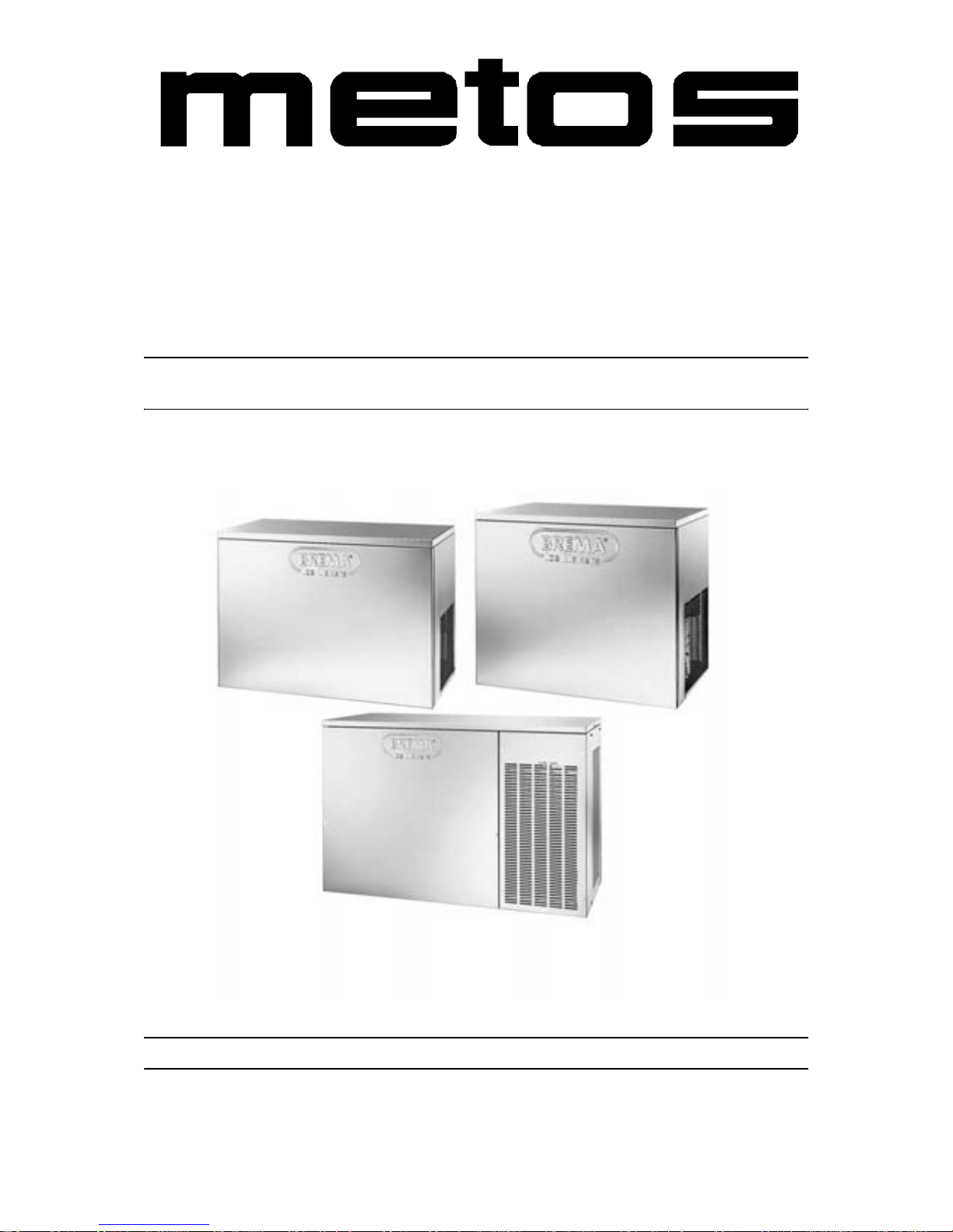
ICE CUBE MAKER WITHOUT BIN
AIR-CONDENSED
WATER-CONDENSED
TYPE: C80, C150, C300
Installation and Operation Manual
S/N: Rev.: 2.4
Page 2

Page 3

17.9.2007 Rev. 2.4
Dear C us tom e r ,
Congratulatio ns on deciding to choose a Metos appliance f or your kitchen activities. You
made an excellent choice. We will do our best to make you a satisfied Metos customer
like thousands of customers we have around the world.
Please read this manual carefully. You will learn correct, safe and efficien t working methods in order to get the best possibl e benefit from the applia nce. Th e instr uctions and hints
in this manual will give you a quick and easy start, and you will soon note how nice it is
to use the Metos equipm ent.
All rights are reserved for technical changes.
You will find the main te chnical da ta on the rating plate fixed to the equipment . When you
need service or technical help, please let us know the serial number shown on the rating
plate. This will make it easier to provide you with correc t se rvice.
For your convenienc e, spa ce is provide d below f or you to r ecord you r lo cal Me tos s ervic e
contact informati on.
METOS TEAM
Metos service phone number:...............................................................................................
Contact person:....................................................................................................................
Page 4

17.9.2007 Rev. 2.4
Page 5

17.9.2007 Rev.
1. General .......................................................................................................... 1
1.1 Symb o l s us e d i n th e manual ...... ................ ........ ................. ........ ................ ........ ........ ... 1
1.2 Symb o l s us e d o n the ap p liance .......... ........ ................. ........ ........ ................ ........ ........... 1
1.3 Chec k i n g the relation of t h e ap p liance and the m an u a l .... ........ ................ ........ ............. 1
2. Safety instructions ........................................................................................ 2
2.1 Safe use .......................................................................................................................... 2
2.1.1 Modifications ......................................................................................................... 2
2.2 Safe t y instructio n s i n c ase o f m a l f u n c t i on ..... ........ ......... ................ ........ ................ ....... 2
2.3 Disposal of appliance .................................................................................................... 2
3. Functional description .................................................................................. 3
3.1 General .......................................................................................................................... 3
3.2 Designed use of appliance ............................................................................................. 3
3.2.1 Other than instructed use ....................................................................................... 3
3.3 Structure ........................................................................................................................ 3
4. Use instructions ............................................................................................. 4
4.1 Use ............ ........ ................ ................ ........ ................ ............... ........ ................ .............. 4
4.2 After use ....................................................................................................................... . 4
4.2.1 C l e aning ........................ ................ ........ ............... ................ ........ ................ .......... 4
4.2.2 Layup ..................................................................................................................... 5
5. Installation ..................................................................................................... 6
5.1 General .......................................................................................................................... 6
5.1.1 Using conditions .................................................................................................... 6
5.2 Possible disturbances from environment (to environment) ........................................... 6
5.3 Stor ag e .................. ................ ................ ........ ............... ................ ........ ................ .......... 6
5.4 Preparing installation ..................................................................................................... 6
5.5 Unpacking ..................................................................................................................... . 7
5.6 Disposal of packaging ................................................................................................... 7
5.7 Installation .......... ........ ................ ........ ................ ............... ........ ................ .................... 7
5.8 Placing of appliance ...................................................................................................... 8
5.9 Connection to power supply mains ............................................................................... 8
5.10 Connection to water mains .......................................................................................... 9
5.11 Dist ance of other fixtur es ........ ........ ................ ......... ........ ................ ........ ................ . 10
6. Troubleshooting .......................................................................................... 11
Page 6

17.9.2007 Rev.
7. Technical specifications .............................................................................. 15
Page 7
17.9.2007 Rev. 2.4
General
1
1. General
Carefully read the instructions in this manual as they contain important information regarding proper, efficient and safe installation, use and maintenance of the appliance.
Keep this manual in a safe place for eventual use by other operators of the appliance.
The installation of this appliance must be carried out in accordance with th e manufacturer’s instructions and following local regulations. The connection of the appliance to the
electric and water supply must be carried out by qualifie d persons only.
Persons using this appliance should be specifically trained in its operation.
Switch off the appliance in the case of failure or malfunction. The periodical function
checks requested in the manua l must be carried out a ccording to the instructions . Have the
appliance serviced by a technically qualified person authorized by the manufacturer and
using original spar e part s.
Not complying with the above may put the safety of the appliance in danger.
1.1 Symbols used in the manual
This symbol in forms about a sit uation whe re a saf ety ri sk m ight be at h and. Give n i nstructions are mandatory in order to prevent injury.
This symbol informs about th e rig ht way to per form in orde r to preve nt bad resul ts, a ppliance damages or hazardous situations.
This symbol informs about recom me ndations and hints that help to get the best performance out of the appliance.
1.2 Sy mbols us e d on the appliance
This symbol on a part informs about electrical terminals behind the part. The removal of
the part must be carried out by qual ified persons only.
1.3 Checking the relation of the appliance and the manual
The rating plate of the appliance indicates the serial number of the appliance. If the ma nuals are missing, it is possible to order new ones from the manufacturer or the local representative. When ordering new manuals it is essential to quote the serial number shown
on the rating plate.
Page 8

17.9.2007 Rev. 2.4
Safety instructions
2
2. Safety instructions
2.1 Safe use
To guarantee the efficiency of the automatic ice cube maker equipped and to ensure its
proper operation, it is essential to adhere to the directions provided by the manufacturer
and to make sure that any maintenance work is carried out exclusively by professionally
qualified staf f. The appli ance is de signed to be used by adult pe rsons. Preve nt any chi ldren
to gain access to it, for example playing with it .
2.1.1 Modifications
Modifying or trying to modify this appliance, in addition to rendering any form of warranty null and void, is extr emely dangerous.
2.2 Safety instructions in case of malfunction
Under no circumstances, try to repai r the applianc e yourself, since an y interventio n on the
part of persons who are not competent, in addition to being dangerous, may cause serious
dama ge to it. In the ev ent of a fai lure, co ntact the de aler who so ld yo u the ap pl ian ce; he
will be able to give you the address of your nearest Authorized Technical Service Centre.
We recommend that you insist on having always and exclusively original spares.
2.3 Disposal of appliance
Should you decide t o scrap your aut omatic ice cube maker, firs t disconnec t the power supply cable from the mains, and then cut the cable off. In addition, proceed as follows:
• Break and remove the door in order to prevent the possible danger of a child getting trapped inside.
• Make su r e n o t l et th e co o l an t g as and oil con tained in th e co m p re s so r in t o t h e en vironment.
• Dispose of or recover the various materials according to the requirements of current regulations valid in your country.
This appliance does not contain coolant that damages the ozone layer.
Page 9

17.9.2007 Rev. 2.4
Functional description
3
3. Functional description
3.1 General
In making ice c ube only cold, p ure drinking water, should be used. Because ice cubes are
mainly used for cooling of beverages for internal use, shall the quality of water used in
making ice cube be con sider ed as im por tant a s the purene ss and g ood s torag e of any othe r
food products.
3.2 Designed use of appliance
Your ice cube maker is designed only for the production of ice cubes.
3.2.1 Other than instructed use
Any use of the automatic ice cube maker other than for the producti on of ice cubes, from
cold drinking water, is to be considered as improper use.
3.3 Structure
The supportin g structu re of the ice c ube m aker is o f s teel and the out er pane ls ar e of stainless steel.
Page 10
17.9.2007 Rev. 2.4
Use instructi ons
4
4. Use instructions
4.1 Use
In making ice cubes, only cold, clean drinking water, should be used. Because ice cubes
are mainly used for cooling of beverages for internal use, shall the quality of water used
in making ice cubes be considered as important as the pureness and good storage of any
other food products.
4.2 After use
4.2.1 Cleaning
Unplug the power cable from the socket, before you start cleaning operations.
For cleaning operations from s urfac es , including subsequent ones, use an ordinary detergent for washing dishes or a solution of water and 10% of vinegar. It´s recommended not
to use abrasive detergent s or powders, since these might damage the surface s .
All cleaning operations must be carried out only after the power and water supply have
been disconnected as described previously.
For cleaning operations from inside and disinfection of the appliance must be carried out
by professionally qualified and authoriz ed s taff.
Page 11
17.9.2007 Rev. 2.4
Use instructi ons
5
4.2.2 Layup
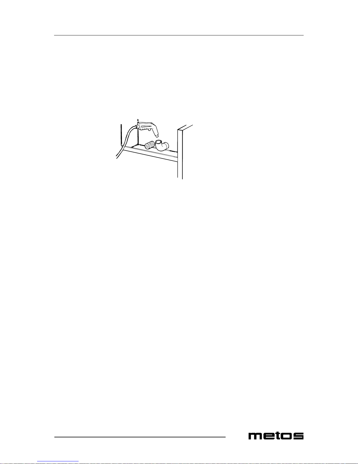
If you do not intend using the a utomatic ice cube maker for a certain period of time, proceed as follows:
• Unplug the power cable from the socket.
• Shut off the water supply by turning off the tap provided during installation.
• Remove the water from the basin (see fig.).
Page 12

17.9.2007 Rev. 2.4
Installation
6
5. Installation
5.1 General
The aut omatic ice cube make r is delive red atta ched to a specia l wood en palle t and pro tected with cardb oard packaging. Inst all ation must be c arrie d out exclusi vel y by quali fie d
and authorized staff, in compliance with current national standards and following the
manufacturer’s instructions.
5.1.1 Using conditions
The best performan ce of the au to matic ice cube maker is achieved at a room temperature
of 20ºC and a water supply temperature of 10ºC. You are advised to install the appliance
with a room temperature of between 10ºC and 35ºC, and a water supply temperature of
between 3ºC and 25ºC. Avoid installing the appliance where it may be exposed to direct
sunlight or near to heat sourc es, such as radiators, stoves, dish-washers, etc.
5.2 Possible disturban c es from environm ent (to enviro nm ent)
If installation is carried out incorrectly, damage and/or injury may ensue to the environment, persons, animals or things. The manufacturer declines all responsibility for any
such damage or injury.
5.3 Storage
The net weight an d th e weight incl uding packa ging of t he i ce c ube maker are gi ven on th e
cover of the packaging . In order to prev ent the oil c ontaine d in th e comp ressor fro m flowing into the coolant circuit, make sure to transport, store, and handle the automatic ice
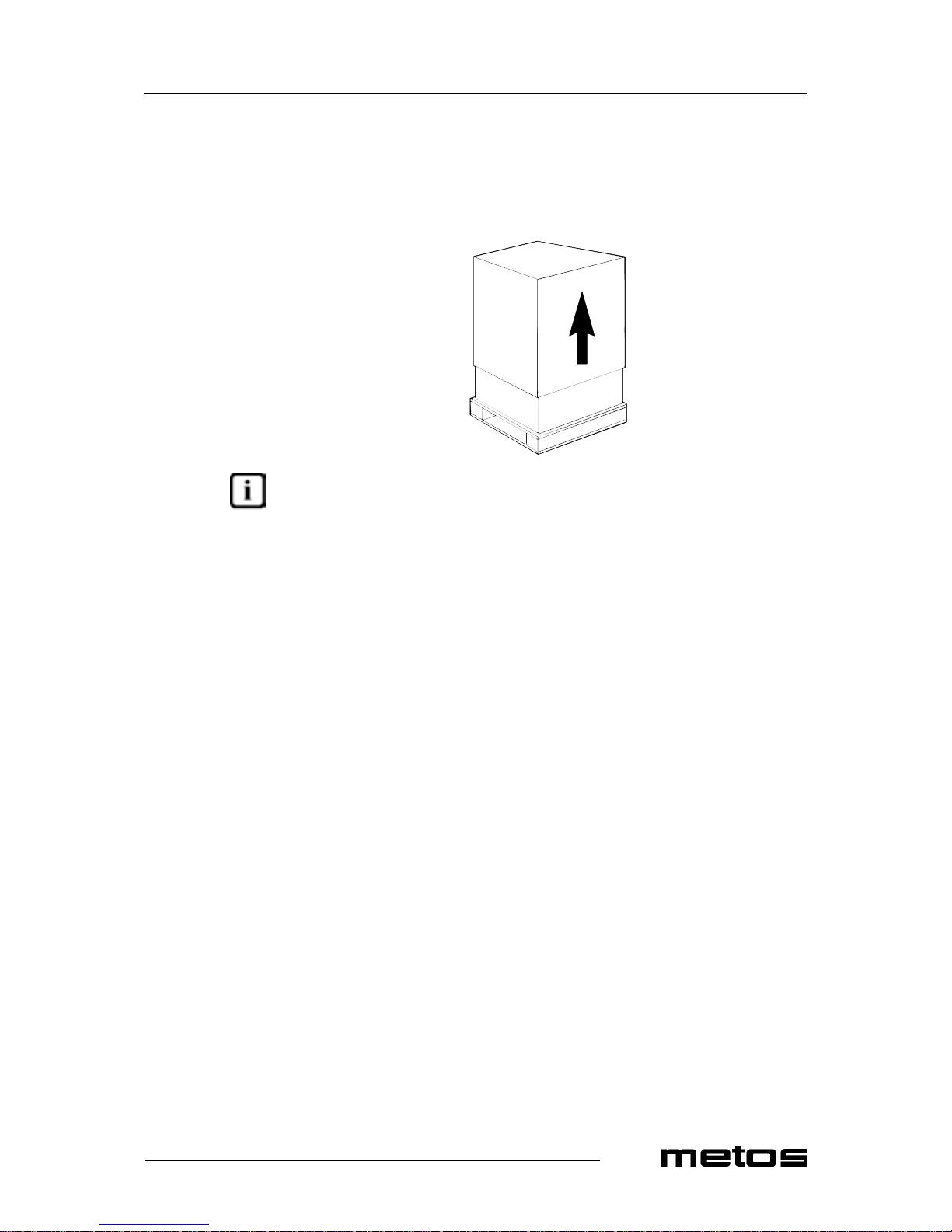
cube maker always kee ping i t stan ding upr ight . Foll ow the in structi ons gi ven on the packaging.
The special wooden pallet, built so that it can be lifted with a fork-lift truck, enables the
appliance to be moved around using ordinary means of handling and lifting.
5.4 Preparing installation
Make sure, that th e i ce cu be maker will be inst all ed on a n perfe ctly l evel. Avoi d ins talli ng
the appliance ne ar heat sources. A floor drain should be found near of the place of installation. The maximum distance being 5 m. Make sure that the meltwater pipe presents a
slope of at least 5% throughout its entire length (5 cm for 1 metre) .
Page 13
17.9.2007 Rev. 2.4
Installation
7
5.5 Unpacking
Remo ve t he ca rdbo ar d pa ckagi ng by cu tti ng th e s tra ps th at hol d it in p lac e; th en sl ide it
off from the top.
Once you have removed the packagi ng, make sure that th e autom atic ice cube maker is in
perfectly good condition. If you are in any doubt, do not use it and contact immediately
the dealer who sold it to you.
Unscrew the screws that fasten the ice cube maker to the wooden pallet.
5.6 Disposal of pa c kaging
All the packaging items (plastic bags, cardboard, polystyrene foam, nails, etc.) must not
be left within reach of chil dren, in that they are potential s ources of danger.
5.7 Installation
The ice cube maker can be installed on a shelves or on a container.
If the ice cube maker i nstalling on the existin g structure , it´s reco mmended doing t he technical checking, that come out if the structure are strong as necessary.
If the ice cube make r instal ling on a cont ainer on our production, the direc tion found al ong
the conta iner.
Use a spirit level to check that the ice cube maker is standing perfectly level.
Page 14
17.9.2007 Rev. 2.4
Installation
8
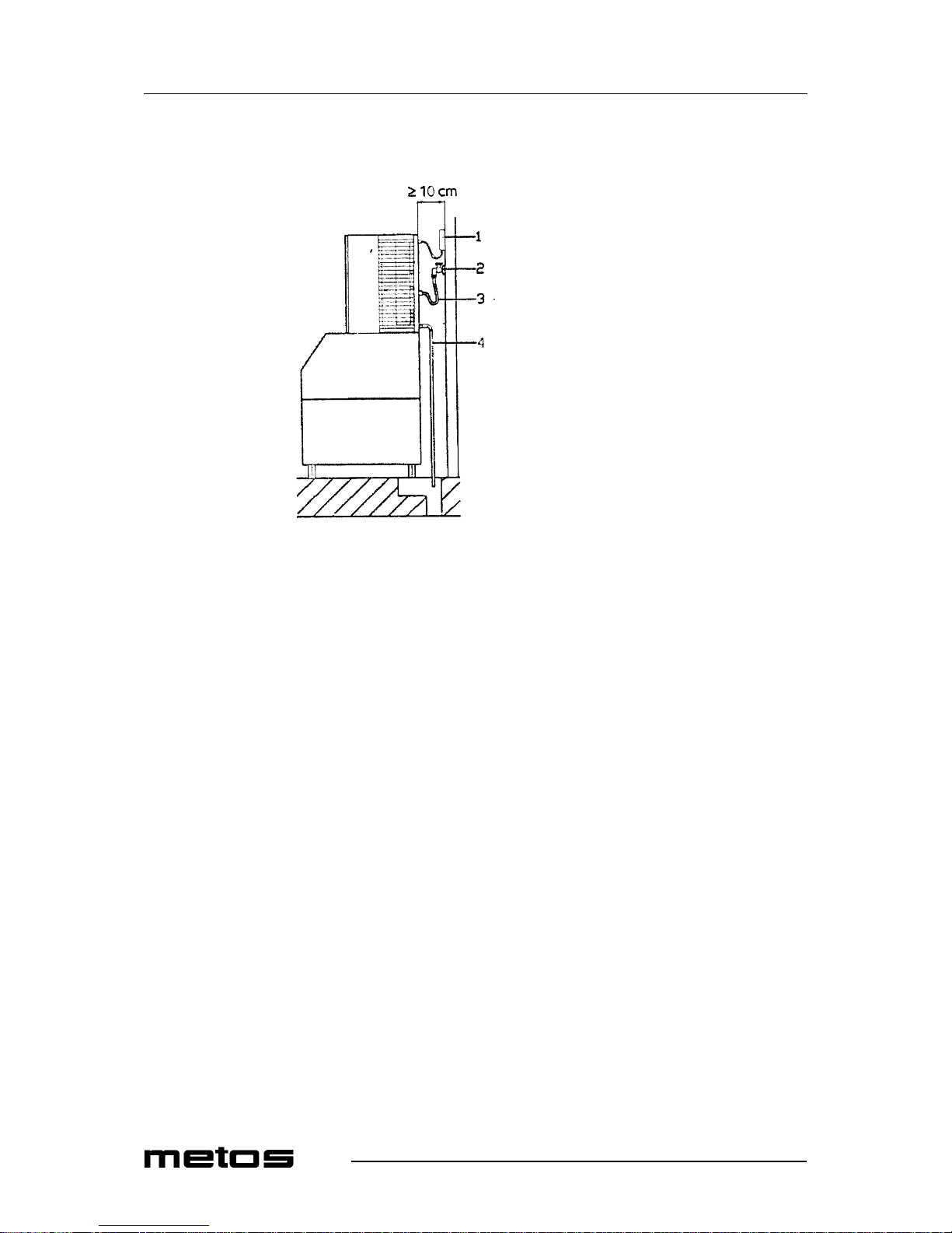
5.8 Placing of appliance
1. Power supply socket
2. Water tap
3. Water supply pipe
4. Water outlet pipe
5.9 Connecti on to power supply mains
The electrical wiring system scheme is attached inside of the rear panel of the ice cube
maker.
To reach this, unplug the power cable from the socket, loosen the screws, which fasten the
front panel and slide it away.
Electric safety of the automatic ice cube maker is achieved solely when the appliance is
properly connected to an efficient earthing system made in compliance with current national safety standards. Make sure that this fundamental safety requirement is respected
and, if you a re in any dou bt, a sk for a tho rough check of the e lect ric s yste m by p rofessi onally qualified and authorized staff. The manufacturer declines all responsibility for damage and/or injury that might ensue from any failure to earth the system properly. It is
essential that the electrical wiring system where the appliance is to be installed should
have adequate current carrying capacity for the maximum power of the appliance, as
shown on the data plate. To achieve a proper and safe installation of the automatic ice
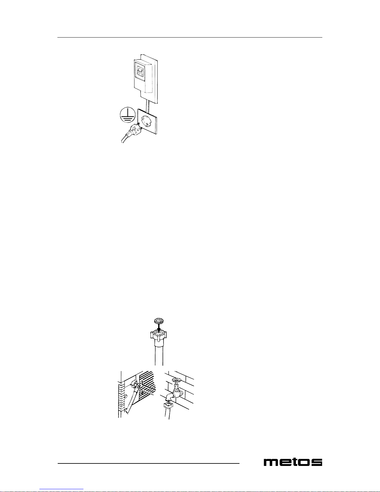
flake maker, it is nece ssary t o prov ide an a ppropria te ea rth ed socket , with a conta ct -opening gap of no less than 3 mm, in accordance with current national safety standards. This
switch must moreover be equipped with fuses (see fig. below).
Page 15
17.9.2007 Rev. 2.4
Installation
9
Make sure to unroll the power supply cable to its entire length and check that it is not
squeezed in any way.
5.10 Connection to water mains
The automatic ic e cube maker is de signed solely for producing ice cube s and must be fed
exclusively with cold water for hum an consumption (drinking water).
The running pressure must be between 1 and 6 Bar.
Connection to the water mains must be made following the manufacturer’s instructions
by professionally qualified staff.
Between th e wat er m ain s and the ch arge pi pe of th e aut o mati c ic e cub e mak er, a tap must
be installed so that the water supply may be shut off if need be.
Where the feed water is particularly hard, you are advised to ins tall a softener. Any solid
particles (e.g., sand) may be eliminated by installing a mechanical filter, which must be
periodically ins p ected and cleaned. These filters must be in compli ance with t h e relevant
national standards in force.
Page 16
17.9.2007 Rev. 2.4
Installation
10
Inse rt the s pec ial s eal s in the two th re aded rin g nuts of the wat er char ge pipe with wit ch
the automatic ice cube maker come supplied (see fig. below) Without exerting excessive
force in order not t o r isk cra cking the unions , fi rmly t igh ten a threa ded ri ng nut on the outlet of the solenoid valve located in the back of the ice cube maker.
The other threaded ring nut must be screwed to the water tap; this too must be provided
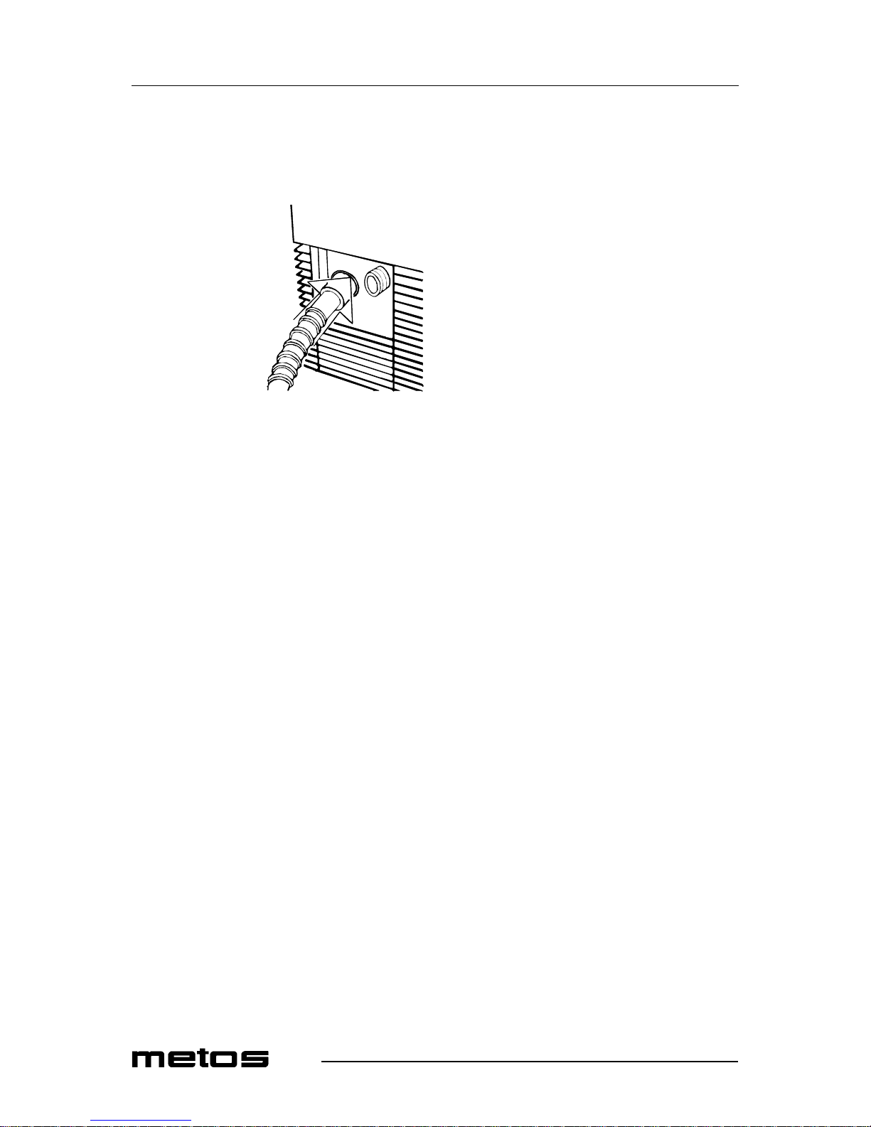
with a 3/4” thread. Insert the water outlet pipe in the housing provided in the back of the
automatic ice cube maker.
Make sure that:
• The internal dia meter of the pipe is 22 mm, as required.
• The water outlet pipe is not throttled in any point throughout its length.
• The outlet pip e ge t down at le ast 15 % downwards on its enti re l ength a nd there ar e
no air pockets in the pipe.
• Direct the wat er outlet pipe into an open drain tr ap.
5.11 Distance of other fixtures
Do not obstruct the ventilation and heat-dissipation grills, since poor air conditioning, in
addition to reducing efficiency and causing poor operation, may also cause serious damage to th e ap p li a nc e.
Leave distance at least 50 mm from th e s ides and 100 mm fromn th e back of the ice cub e
maker, to make sure that air conditioning is sufficient.
Page 17
17.9.2007 Rev. 2.4
Troubleshooting
11
6. Troubleshooting
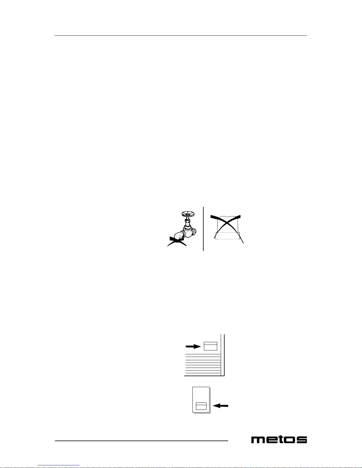
Should the appl ian ce fa il to produ ce ic e, be fore c allin g on the Aut hori zed T echni cal Se rvice Centre, first check carefully that :
• The water supply tap provided in the istallation phase is open (see fig.).
• The electri c power is reaching the appliance, the plug is properly inserted, and the
corresponding s w itch is in the “on” position.
• In the event of e xcessive noise, check that the appl iance doe s not come into contact
with other fixtures or sheet metal that may cause noise or vibrations.
• Should any traces of water appear, check that the discharge hole of the container
is not obstructed, that the water feed and discharge pipes are correctly connected
up and do not present any throttling or damage.
Once the abo v e ch eck s hav e bee n m ade, i f t h e ap p lian ce wer e s ti ll to pr es ent m alf unc ti oning, switch off the power s upply via the switch provi ded during th e installa tion phase , pull
out the plug from its socket, c lose the ta p conne cting the ap pli ance u p to the wat er su pply,
and call the nearest Authorized Technical Service Centre.
In order to obtain a faster and more efficient i ntervention, when you call the Centre, indicate the model of the appliance prec isely, and its seri al number. These can be read on the
matriculation lable stuck on the rear of the appliance or on the cover of this manual (see
fig.).
MANUAL
Page 18
17.9.2007 Rev. 2.4
Troubleshooting
12
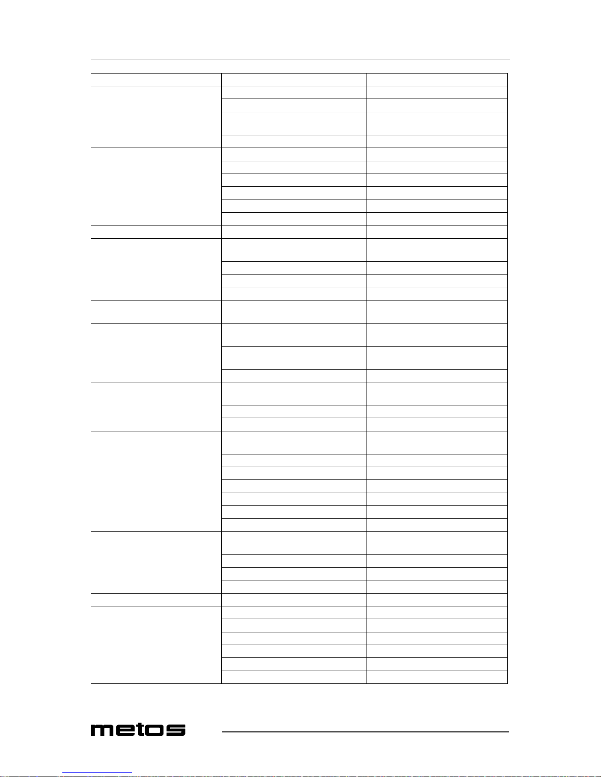
MALFUNCTION Possible cause Operation
Ice cube maker does not function Appliance does not function Check power supply
Thermost at in the container does not func. Change the thermostat
Safety thermostat of th e condenser does
not functi on.
Chang e th e th ermostat
Safety pressure switch has cut off (C300) Settle the pressure switch
Appliance functions, but does not
make proper ice
The condenser is blocked Clean the condenser
There is no coolant gas Find leakage, fix it, vacuumize and fil up
Warm gas valve leaks Fix or change the valve
Compressor does not pump Change the com pressor
Air conden sed models Check the fan, change if needed
Condenser fan does not functi on Check the f unc tion . o f the pr essur e swi tch
Water conta iner receives no water Solenoid valve does n ot open or is blocked Change the valve
Water conta in er has no wate r or wate r
runs out during cycle
Overflow pipe of the basin is on a too low
level
Set the pipe on the right level or renew it
Dirty nozzles Clean or change the nozzles
Water basi n leaks Find the leakage and fix/change the basin
Sieve of the water valve is blocked Clean the sieve
Appliance doe s n ot s top w hen t he c on-
tainer is filled
Malfunct ioning thermostat of the i ce cube
container
Check the probe, adjust/c hange the thermostat
Safety thermostat for overheating
stops the apparatus
The water supply valve does not open Change the pressure switch
The water condenser is obstructed Clean the wa ter condenser (slime remov-
al)
The appliance receive s no w ater Check the water supply
Appliance st ays i n funct i on d uring the
cooling phase
Malfunctioning ther mostat of the evapora-
tor
Chang e th e th ermostat
The reel of the warm gas cooling valve Change the reel
The slide pulse is faulty Change the slide pulse
Collects ice under the evaporator or
frozes throughout
Malfunctioning ther mostat of the evapora-
tor
Chang e th e th ermostat
Warm gas valve leaks Change valve
The slide pulse is faulty Change the slide pulse
The appliance has not enough liquid Find leakage, fix it, vacuumize and fill up
Irregular or incomplete melting Not enough liquid Find leakage, fix it, vacuumize and fill up
Dirty evaporator Clean the evaporator (cautiously)
The water va lve does not get clos ed Change the valve
Lack of water Water supply or drain pipe is not connect-edCheck the connections
The water pump leaks Change the pump
Bad pipe connections Check the pipe connections
Plastic drain water coupl er is broken Check fix/change
Irregular ice-cubes Lime containing water
Compressor is noisy or functions ir-
regularly
Malfunctions in the electrical system Check the electrical system
Start condenser is malfunc tioning Change the condenser
Start relay is malfunction ing Change the relay
Uneve n st art Chang e th e co m p ressor
Shakes at st art up Chang e th e co m p re ssor
Extremely noisy functioning Change the compressor
Page 19
17.9.2007 Rev. 2.4
Troubleshooting
13
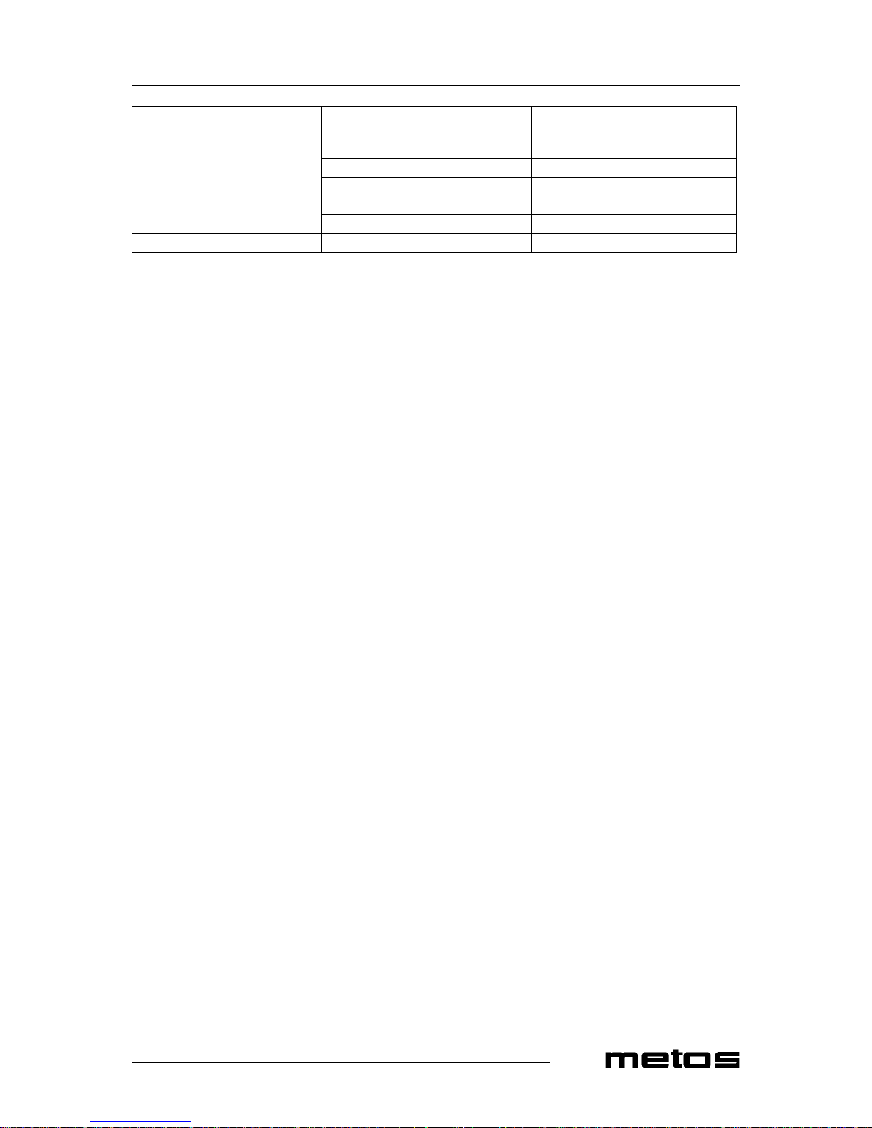
Ice cube production reduc es The condenser or the a ir filt er is obs truc te d Clean the condenser or the filter
The water does not exit from the ice con-
tainer
Drain wa ter hose is throttled/blocked
Not enough l iquid Find leakage, fix it, vacuumize and fill up
The warm gas valve leaks Fix or renew the valve
The water val ve le aks or c han ges the w ater Renew the water solenoid valve
The suction valves of the compressor leak Tenew the compressor
Melting phase does not function Warm gas valve does not open Check the valve, fix it or renew
Page 20

17.9.2007 Rev. 2.4
Troubleshooting
14
Page 21

17.9.2007 Rev. 2.4
Technical specifications
15
7. Technical specifications
Electric diagram 24126 rev2 (valid from 2004.07.22)
Electric diagram 24127
Electric diagram 24127 rev3 (valid from 2004.07.22)
Electric diagram 24128
Electric diagram 24128 rev5 (Valid from 20040722)
Electric diagram 24129/3
Electric diagram 24130
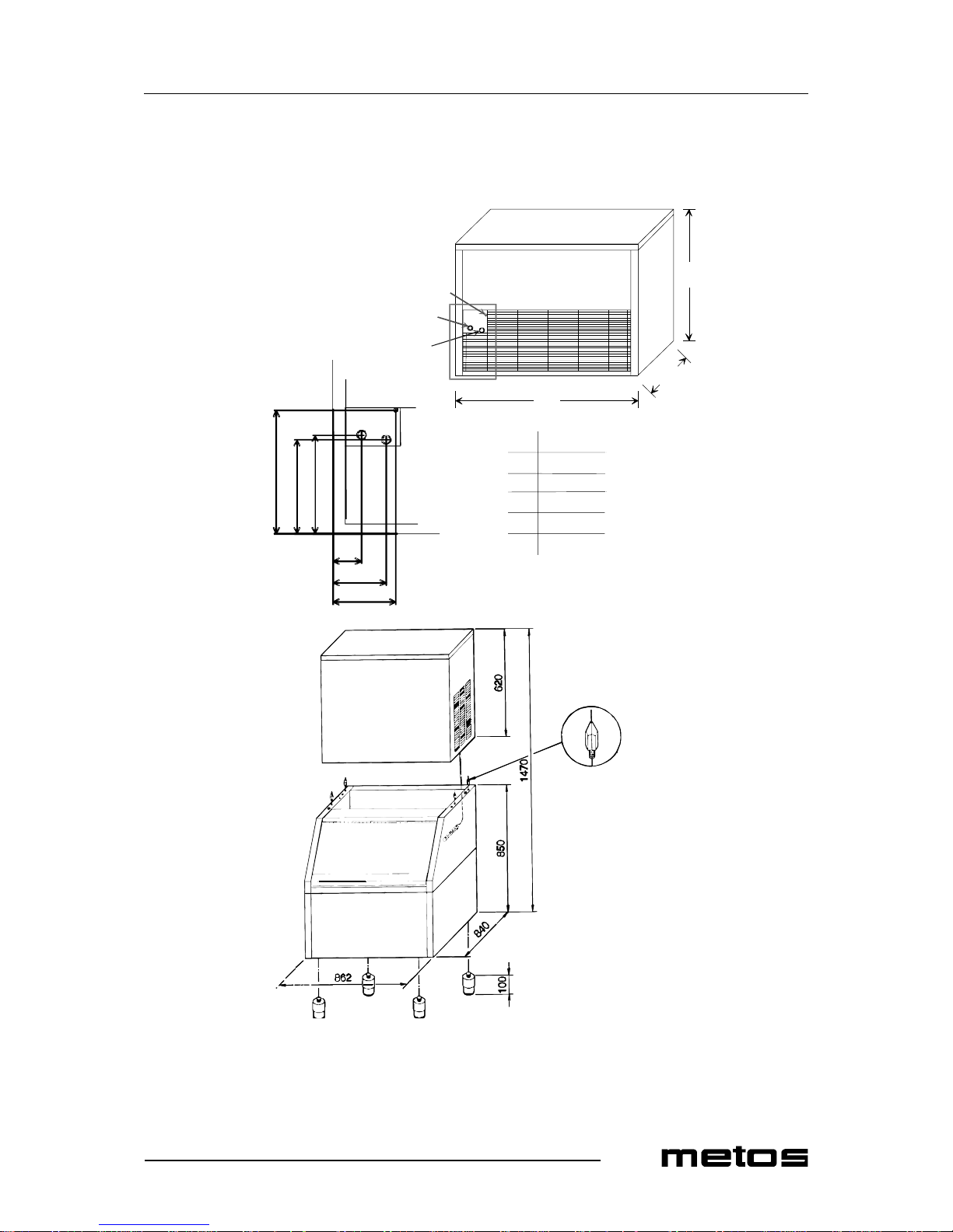
Installation drawing C80
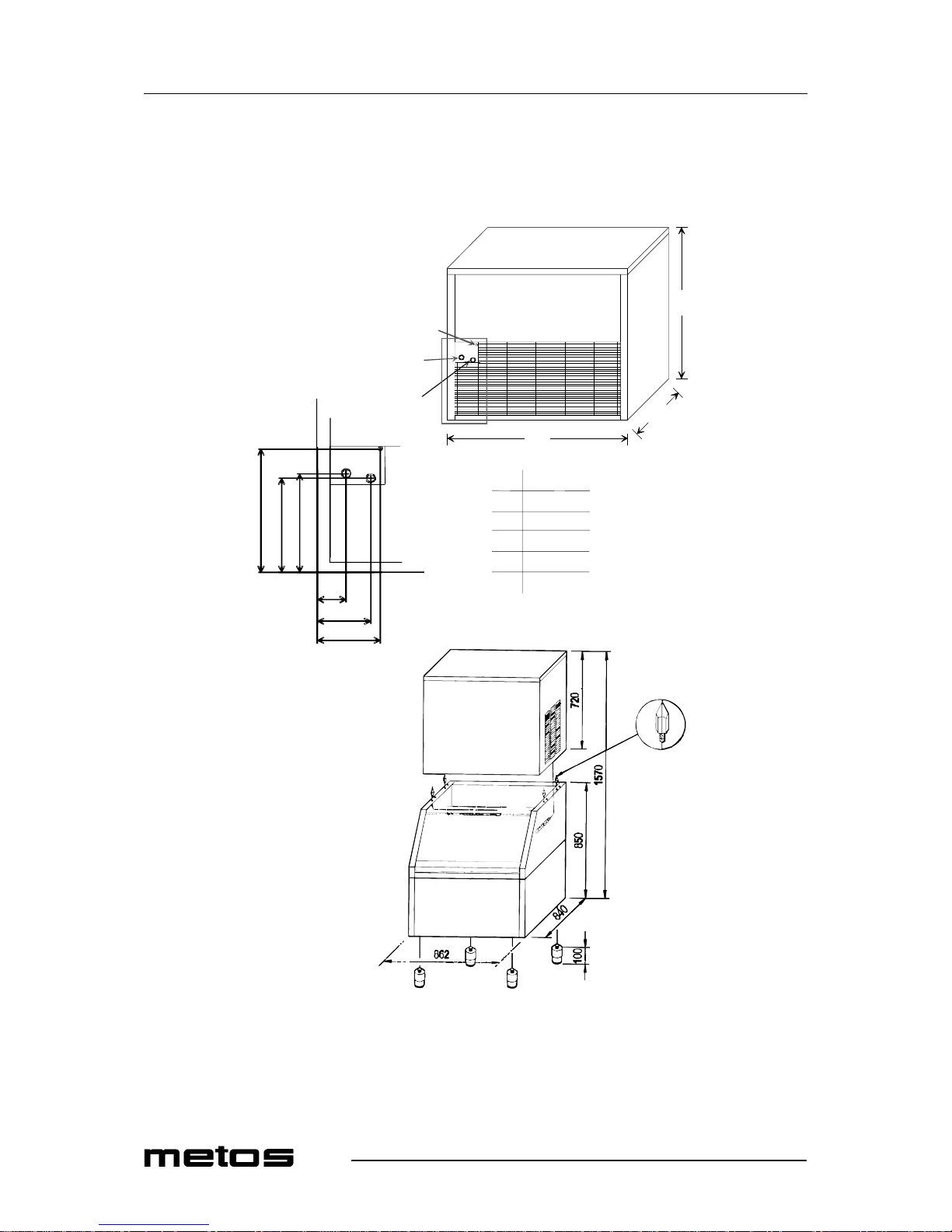
Installation drawings C150
Installation drawing C300
Marine foot
Page 22
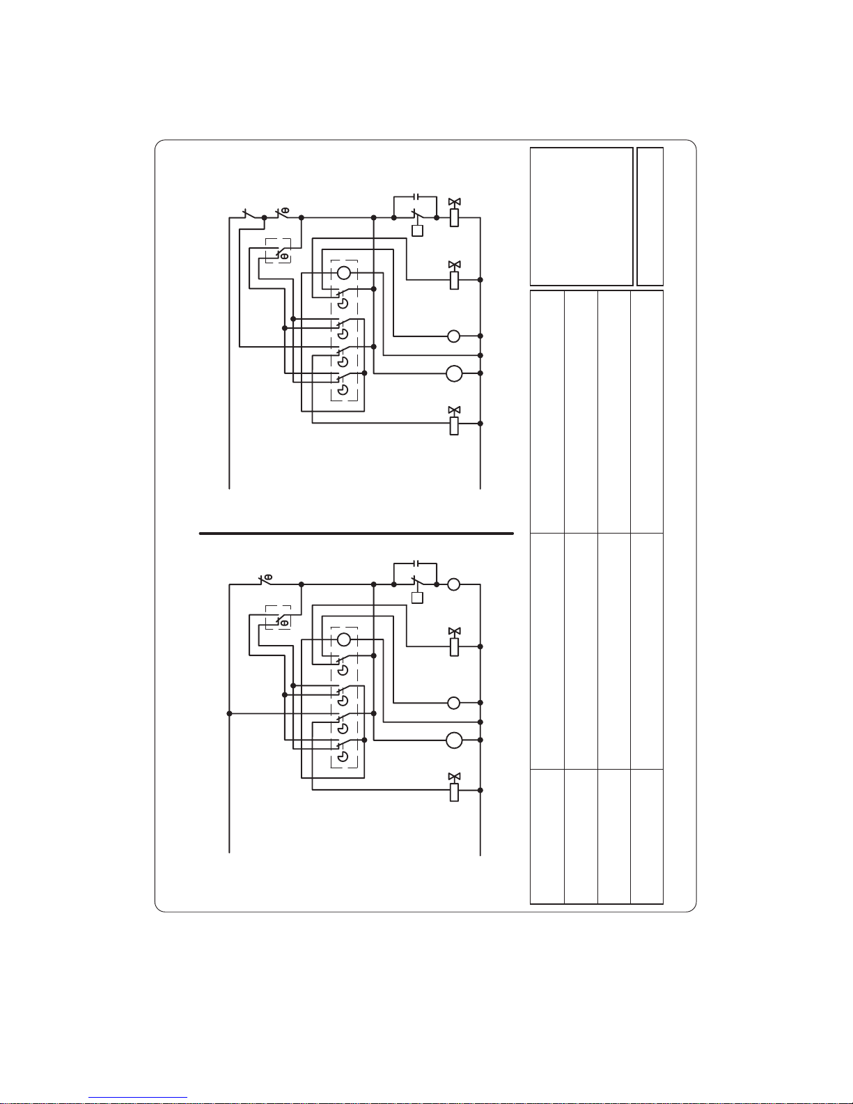
Electric dia gram 24126 rev2 (valid from 2004.07.22)
SCHEMA ELETTRICO / ELECTRIC DIAGRAM
VERSIONE AD ARIA / AIR COOLED VERSIONE AD ACQUA / WATER COOLED
N
BL
BL
BL
N
M
G
M
B
A3
A4
A2
N
A1
N
RN
M
BN
RN
BN
M
N
M
N
RN
BN
4
3
M
BL
BL
BL
N
M
G
A4
A3
M
B
R
A1
A2
N
N
N
BN
RN
RN
BN
M
M
RN
BN
N
N
4
3
M
P
RS
RS
N
N
N
C
BLBL
R
M
BL
RS
P
N
N
C
N
BL
M
RS
# #
7
4
6
N N
3
L
2
1
L
5
7
4
6
3
2
1
9
8
10
5
7a
10
Cod. 24126 - Rev. 02
B = VALKOINEN / WHITE
BL = SININEN / BLUE
BN = VALKO-MUSTA / WHITE-BLACK
G = HARMAA / GREY
M = RUSKEA / BROWN
N = MUSTA / BLACK
R = PUNAINEN / RED
RN = PUNA-MUSTA / RED-BLACK
RS = ROSA /PINK
4.
KOMPRESSORI
COMPRESSOR
1.
TERMOSTAATTI ALLAS
BIN THERMOSTAT
10.
PAINEKYTKIN
PRESSURE SWITCH
8.
VEDENSYÖTTÖV. LAUHDUTTIMELLE
WATERINLET VALVE FOR CONDENSER
3.
AJASTIN
TIMER
9.
TERMOSTAATTI
SAFETY THERMOSTAT
2.
TERMOSTAATTI HÖYRYSTIN
EVAPORATOR THERMOSTAT
7a.
PUHALLINMOOTTORI
FAN M OTOR
5.
KUUMAKAASUVENTTIILI
HOT GAS VALVE
7.
PUMPPU
PUMP
6.
VEDENSYÖTTÖV. HÖYRYSTIMELLE
WATER INLET VALVE FOR EVAPORATOR
# 6 = RANCO K59
# 2 = RANCO K22
C80 24126r2.pdf valid from 20040722
Page 23
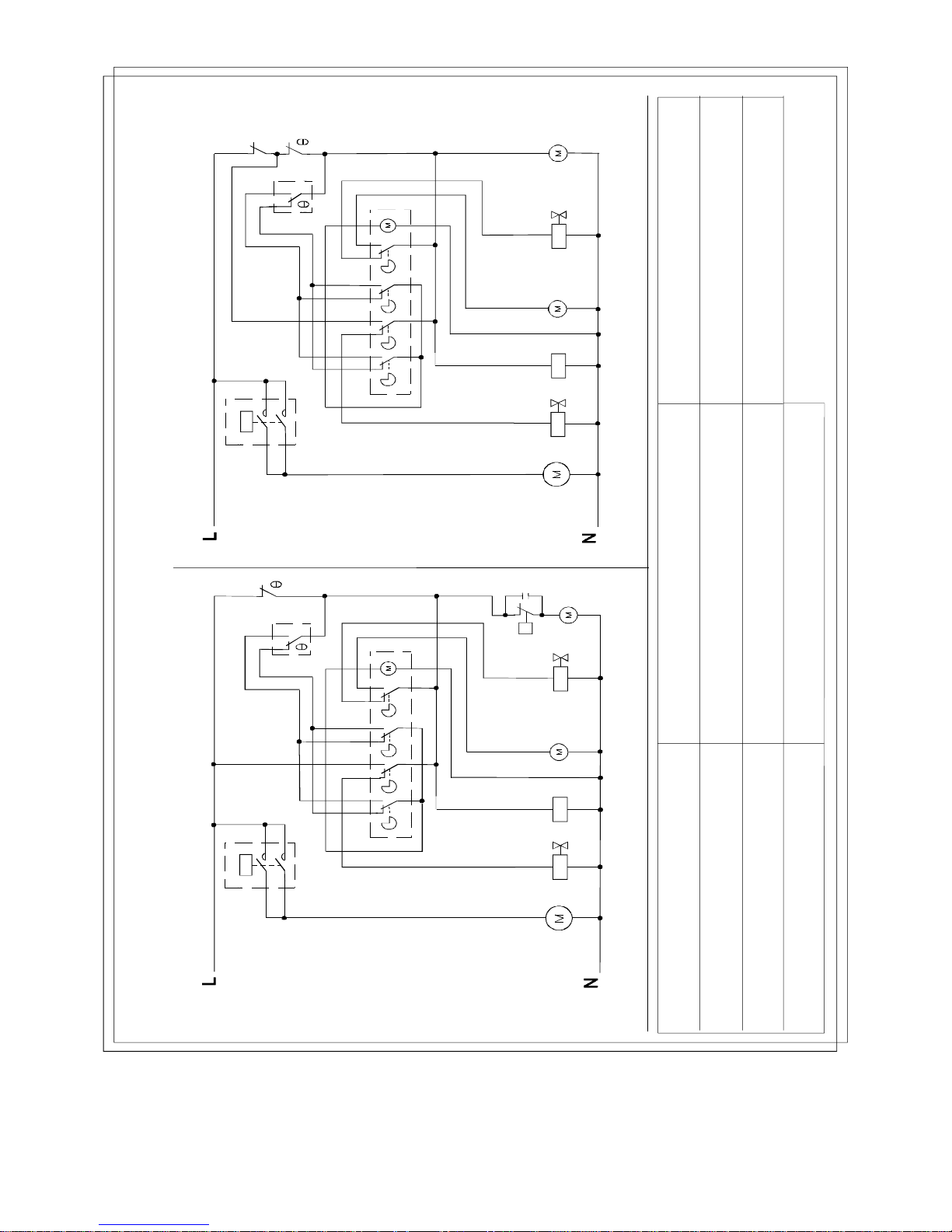
Electric diagram 241 27
1.
TANK THERMOSTAT
ALTAAN TERMOSTA AT TI
TANK THERMOSTAT
2.
EVAPORATOR THERMOSTAT
HÖYRYSTIMEN TER MO ST AAT TI
EVAPORATOR TERMOSTAT
3.
TIMER
AJASTIN
TIDGIVARE
4.
5.
HOT GAS VALVE
KUUMAN KAASUN VENT T IILI
VARM GAS VENTIL
6.
WATER INLET VALVE FOR EV APOR AT OR
HÖYRYSTIMEN VEDEN TU LOVEN T T IILI
VATTENS INLOPPSVENTIL TILL EVAPORATOR
7.
PUMP
PUMPPU
PUMPA
COMPRESSOR
KOMPRESSORI
KOMPRESSOR
9.
SAFE TY THERMOSTAT
TURVATERMOSTAATTI
SÄKERHETSTERMOSTAT
10.
PRESSURE SWITCH
PAINEKYTKIN
PRESSOSTAT
7a.
FAN MOTOR
TUULETTIMEN MOOTTORI
FLÄKT MOTOR
11.
CONTACTOR
KONTAKTORI
KONTAKTOR
ELECTRIC DIAGRAM / SÄHKÖKAAVIO / ELSCHEMA
AIR COOLED / ILMAJÄÄHDY TTEINEN / LUFTKYLD
WATER COO LED / VESIJ ÄÄHDYTTEINEN / VATTENKY LD
7
5
3
A1
A2
A3
2
9
A4
1
4
3
2
7a
7
6
11
K1
4
7
5
10
P
C
3
A1
A2
A3
2
A4
1
4
3
2
7a
7
6
2
11
111
K1
K1
4
11
COD.24127
4
3
2
111
K1
11
4
3
C150A/W 220/50-60
Page 24
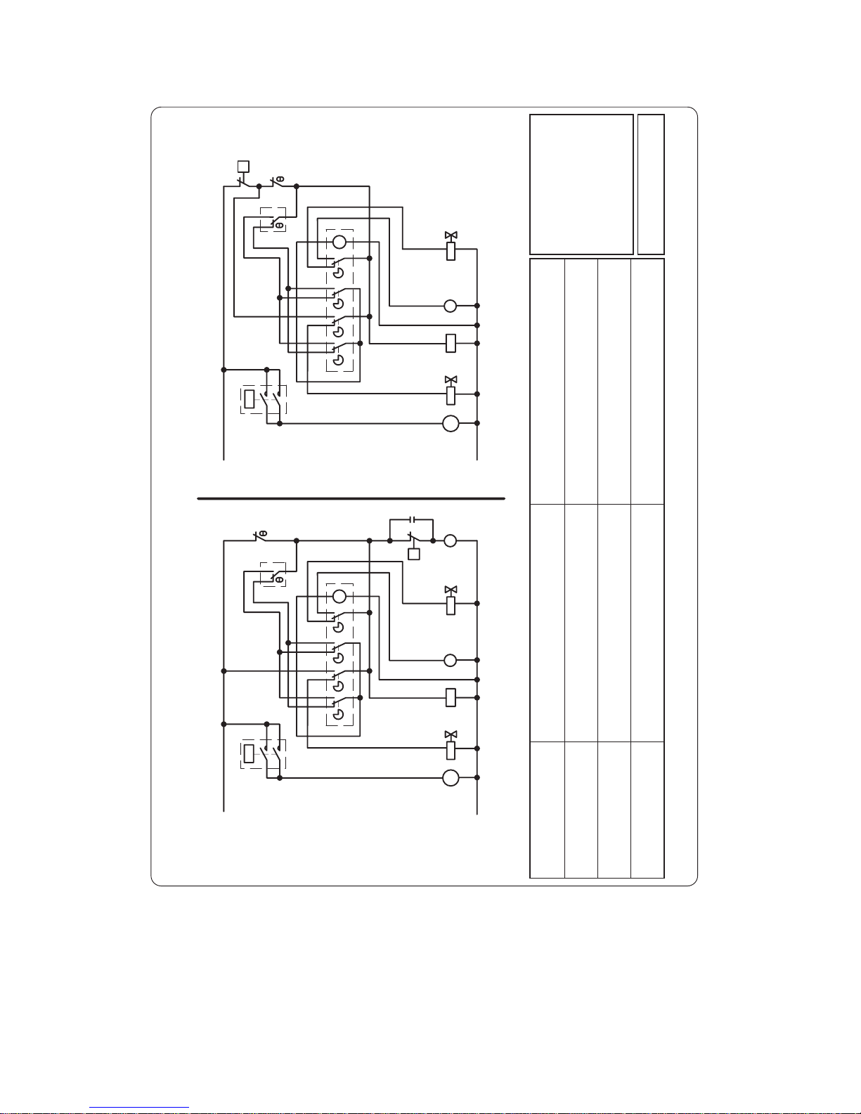
Electric dia gram 24127 rev3 (valid from 2004.07.22)
SCHEMA ELETTRICO / ELECTRIC DIAGRAM
VERSIONE AD ARIA / AIR COOLED VERSIONE AD ACQUA / WATER COOLED
N
BL
BL
BL
N
N
M
B
A3
A4
A2
N
A1
N
RN
M
BN
RN
BN
M
N
M
N
RN
BN
4
3
M
BL
BL
N
A4
A3
M
B
R
A1
A2
N
N
N
BN
RN
RN
BN
M
M
RN
BN
N
N
4
3
M
BLBL
R
M
BL
RS
P
G
G
C
G
BL
M
RS
# #
6
5
K1
2
1
M
K1 K1
K1
6
2
5
1
M
G
G
M
M
G
N
G
M
M
M
P
7
6
N N
3
L
2
1
L
5
7
6
3
2
1
5
7a
10
11
4
11
4
23
Cod. 24127 - Rev. 03
B = VALKOINEN / WHITE
BL = SININEN / BLUE
BN = VALKO-MUSTA/ WHITE-BLACK
G = HARMAA / GREY
M = RUSKEA / BROWN
N = MUSTA / BLACK
R = PUNAINEN / RED
RN = PUNA-MUSTA / RED-BLACK
RS = ROSA /PINK
4.
KOMPRESSORI
COMPRESSOR
1.
TERMOSTAAATTI ALLAS
BIN THERMOSTAT
23.
PAINEKYTKIN
SAFETY PRESSURE SWITCH
10.
PAINEKYTKIN
PRESSURE SWITCH
3.
AJASTIN
TIMER
11.
KONTAKTORI
CONTACTOR
2.
TERMOSTAATTI HÖYRYSTIN
EVAPORATOR THERMOSTAT
7a.
PUHALLINMOOTTORI
FAN M OTOR
5.
KUUMAKAASUVENTTIILI
HOT GAS VALVE
7.
PUMPPU
PUMP
6.
VEDENSYÖTTÖV. HÖYRYSTIMELLE
WATER INLET VALVE FOR EVAPORATOR
# 6 = RANCO K59
# 2 = RANCO K22
C150 24127r3.pdf valid from 20040722
Page 25
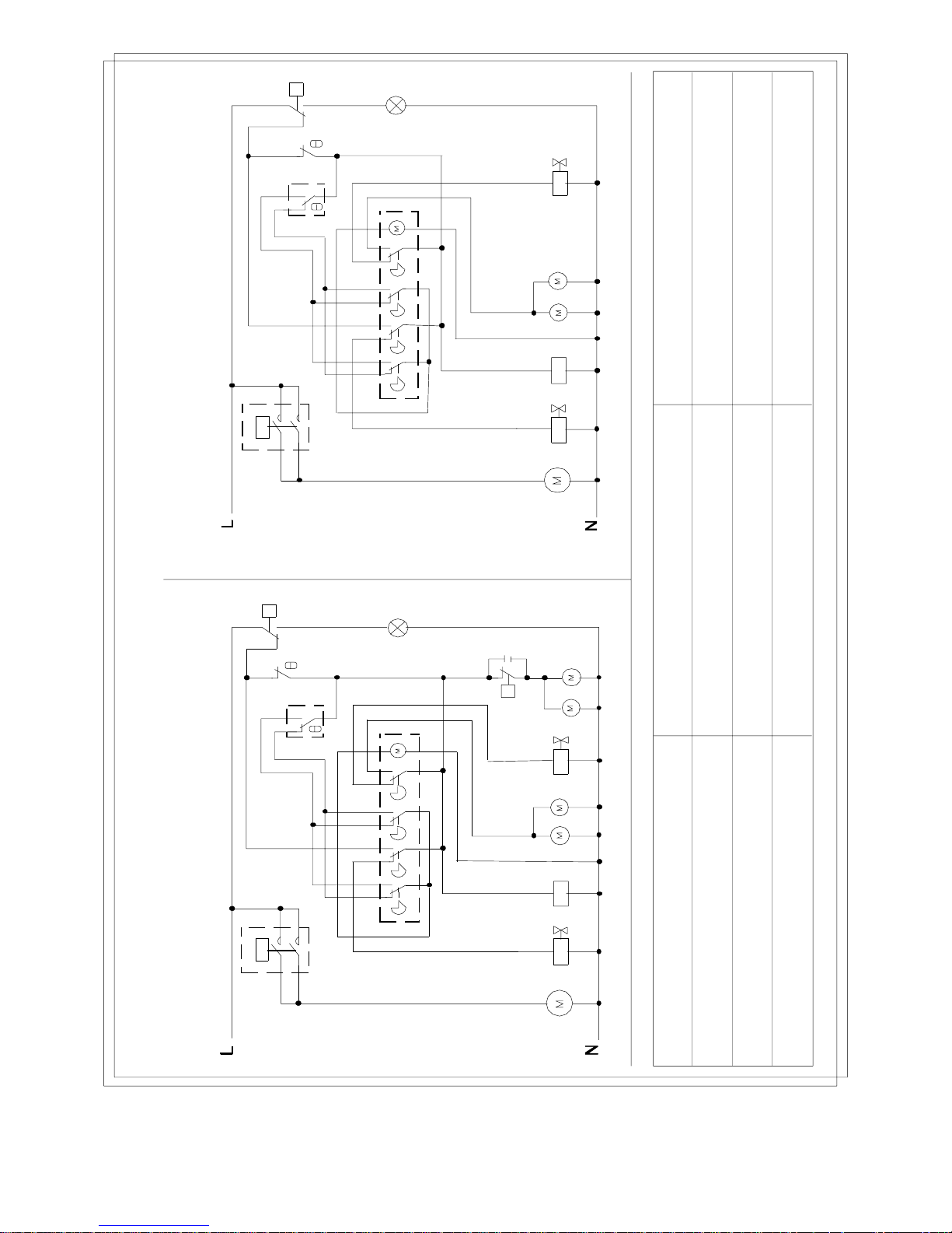
Electric diagram 241 28
1.
TANK THERMOSTAT
ALTAAN TERMOSTAATTI
TANK THERMOSTAT
2.
EVAPORATOR THERMOSTAT
HÖYRYSTIMEN TER MOSTAATTI
EVAPORATOR TERMOSTAT
3.
TIMER
AJASTIN
TIDGIVARE
4.
5.
HOT GAS VALVE
KUUMAN KAASUN VENTTIILI
VARM GAS VEN TIL
6.
WATER INLET VALVE FOR EVAPORATOR
HÖYRYSTIMEN VE DEN TULOVENTTIILI
VATTENS INLOPPSVENTIL TILL EVAPORATOR
7.
PUMP
PUMPPU
PUMPA
COMPRESSOR
KOMPRESSORI
KOMPRESSOR
23.
SAFETY PRESSURE SWITCH
TURVAPAINEKYTKIN
SÄKERHETS TRYCKBRYTARE
10.
PRESSURE SWITCH
PAINEKYTKIN
PRESSOSTAT
7a.
FAN MOTOR
TUULETTIMEN MOOTTORI
FLÄKT MOTOR
11.
CONTACTOR
KONTAKTORI
KONTA KTOR
H1.
ORANGE PILOT LIGH T: ALARM
ORANSSI MERKKIVALO: HÄLYT YS
ORANGE SIGNA LLJUS: ALARM
AIR COOLED / ILMAJÄÄHDYTTEINEN / LUFTKYLD
WATER COOLED / VESIJÄÄHDYTTEINEN / VATTENKYLD
75
3
A1
A2A3
2
A4
1
4
32
7
6
11
K1
4
7
5
10
P
C
3
A1
A2
A3
2
A4
1
4
32
7a
7
6
2
11
111
K1
K1
4
11
43
2
111
K1
11
43
COD. 24128/2
7
7
P
H1
23
7a
P
23
H1
ELECTRIC DIAGRAM / SÄHKÖKAAVIO / ELSCHEMA
C300 A/w 220/50-60
Page 26
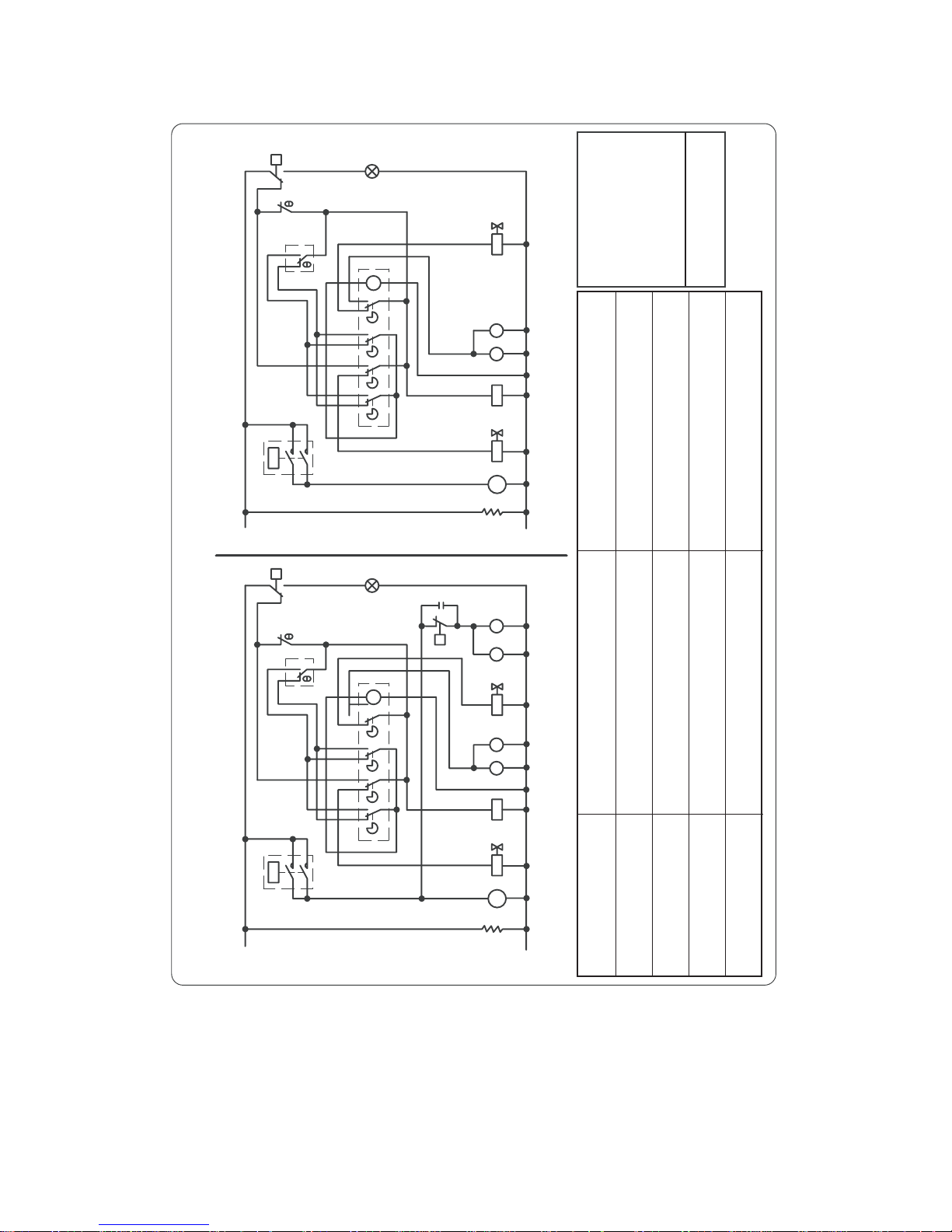
Electric diagram 24128 rev5 (Val id from 20040722)
SCHEMA ELETTRICO / ELECTRIC DIAGRAM
VERSIONE AD ARIA / AIR COOLED VERSIONE AD ACQUA / WATER COOLED
N
BL
BL
BL
N
N
M
B
A3
A4
A2
N
A1
N
RN
M
BN
RN
BN
N
M
N
RN
BN
4
3
M
BL
R
M
BL
P
G
G
C
G
#
6K18
M
K1
G
G
M
M
M
M
BL
RS
MM
P
M
M
BL
M
BL
G
N
A4
BL
K1
M
BL
M
R
B
N
A3
A2
N
N
A1
M
RN
K1
G
M
M
M
M
BN
BN
RN
BN
N
4
#
3
RN
N
P
B
B
RS
RS
B
B
M
M
RS
N
7
5
8
6
5
7
BL
Rc
N
BL
Rc
N
7
6
N
3
L
2
1
5
7a
10
11
4
7
7a
23
N
4
6
5
77
3
11
L
2
1
23
H1 H1
Cod. 24128 - Rev. 05
B = VALKOINEN / WHITE
BL = SININEN / BLUE
BN = VALKO-MUSTA / WHITE-BLACK
G = HARMAA / GREY
M = RUSKEA / BROWN
N = MUSTA / BLACK
R = RPUNAINEN / RED
RN = PUNA.-MUSTA / RED-BLACK
RS = ROSA /PINK
4.
KOMPRESSORI
COMPRESSOR
1.
TERMOSTAATTI ALLAS
BIN THERMOSTAT
23.
PAINEKYTKIN
SAFETY PRESSURE SWITCH
10.
PAINEKYTKIN
PRESSURE SWITCH
3.
AJASTIN
TIMER
11.
KONTAKTORI
CONTACTOR
2.
TERMOSTAATTI HÖYRYSTIN
EVAPORATOR THERMOSTAT
7a.
PUHALLINMOOTTORI
FAN M OTOR
5.
KUUMAKAASUVENTTIILI
HOT GAS VALVE
7.
PUMPPU
PUMP
6.
VEDENSYÖTTÖV. HÖYRYSTIMELLE
WATER INLET VALVE FOR EVAPORATOR
H1.
HÄLYTYSVALO, ORANSSI
ORANGE PILOT LIGHT: ALARM
# 6 = RANCO K59
# 2 = ATEAA33 - RANCO K61 -
RANCO K22
Rc.
VASTUS
COMPRESSOR RESISTANCE
C300 24128r5.pdf valid from 20040722
Page 27
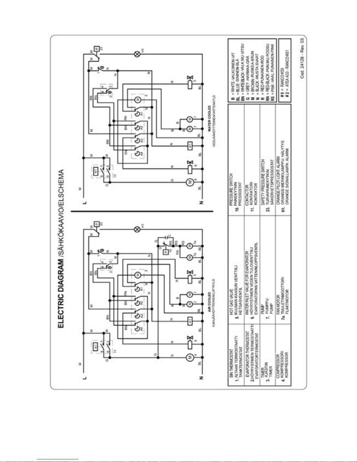
Electric diagra m 24129/3
Page 28
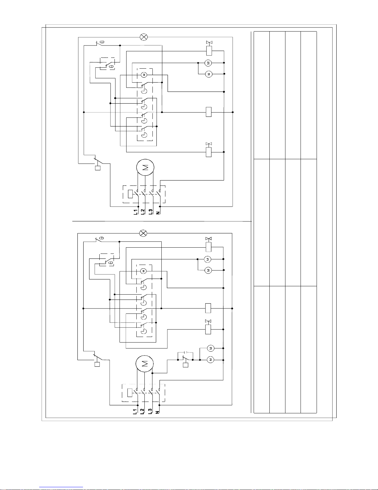
Electric diagram 241 30
1.
TANK THERMOSTAT
ALTAAN TERMOSTAATTI
TANK THERMOSTAT
2.
EVAPORATOR THERMOSTAT
HÖYRYSTIMEN TERMOSTAATTI
EVAPORATOR TERMOSTAT
3.
TIMER
AJASTIN
TIDGIVARE
4.
5.
HOT GAS VALVE
KUUMAN KAASUN VENTTIILI
VARM GAS VENTIL
6.
WATER INLET VALVE FOR EVAPORATOR
HÖYRYSTIMEN VEDEN TULOVENTTIILI
VATTENS INLOPPSVENTIL TILL EVAPORATOR
7.
PUMP
PUMPPU
PUMPA
COMPRESSOR
KOMPRESSORI
KOMPRESSOR
10.
PRESSURE SWITCH
PAINEKYTKIN
PRESSOSTAT
7a.
FAN MOT OR
TUULETTIMEN MOOTTORI
FLÄKT MOTOR
11.
CONTACTOR
KONTAKTORI
KONTAKTOR
ELECTRIC DIAGRAM / SÄHKÖKAAVIO / ELSCHEMA
AIR COOLED / ILMAJÄÄHDYTTEINEN / LUFTKYLD
WATER COOLED / VESIJÄÄHDYTTEINEN / VATTENKYLD
7
5
10
P
C
3
A1
A2
A3
2
A4
1
4
32
7a
7
6
11
K1
K1
4
11
COD. 24130/2
7
7a
H1
P
23
7
5
3
A1
A2
A3
2
A4
1
4
32
6
11
K1
K1
4
11
7
H1
P
23
23.
SAFETY PRESSURE SWITCH
TURVAPAINEKYTKIN
SÄKERHETS TRYCKBRYTARE
H1.
ORANGE PILOT LIGHT: ALARM
ORANSSI MERKKIVALO: HÄLYTYS
ORANGE SIGNALLJUS: ALARM
C300 400/3/50 - 460/3/60
Page 29
17.9.2007 Rev. 2.4
Technical specifications
23
Installa tion drawing C80
1. Water OUT, diam. 24mm
2. Wa t er IN, diam. 3 / 4 ”
3. Power cable
C 80
862 mm
6
2
0
m
m
4
7
0
m
m
A
B
C
D
E
F
69 mm
226 mm
127 mm
213 mm
125 mm
284 mm
1
2
3
F
D
B
A
C
E
3
2
1
Page 30
17.9.2007 Rev. 2.4
Technical specifications
24
Installatio n d r aw i n gs C150
1. Water OUT, diam. 24mm
2. Wa t er IN, diam. 3 / 4 ”
3. Power cable
C 150
862 mm
7
2
0
m
m
5
5
5
m
m
A
B
C
D
E
F
69 mm
297 mm
126 mm
284 mm
140 mm
355 mm
1
2
3
F
D
B
A
C
E
3
2
1
Page 31
17.9.2007 Rev. 2.4
Technical specifications
25
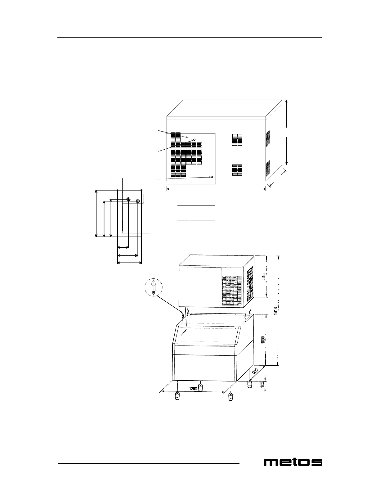
Installation dra w ing C300
1. Water OUT, diam. 24mm
2. Wa t er IN, diam. 3 / 4 ”
3. Power cable
C 300
1250 mm
8
1
8
m
m
5
8
0
m
m
A
B
C
D
E
F
29 mm
73 mm
39 mm
582 mm
1222 mm
748 mm
1
2
3
F
D
B
A
C
E
3
2
1
Page 32
17.9.2007 Rev. 2.4
Technical specifications
26
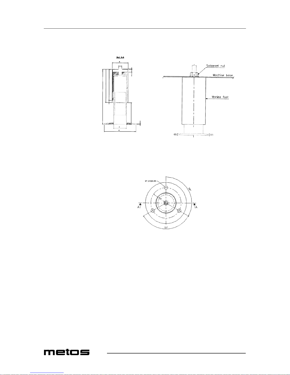
Marine foot
New marine foot
170,5
103
96
TUBO IN ACC INOX
TUBO IN ACC INOX
40
100
25
7
675
50
M10
1,58,5
+0,2
-0,2
Installation of marine foot:
Page 33
17.9.2007 Rev. 2.4
Technical specifications
27
A=AIR-CONDENSED, W=WATER-CONDENSED
80=C80, 150=C150, 300=C300
A=3/N/PE∼400/230V 50Hz , B= ∼250 V 16A 50H z, H=3/PE∼230V 50Hz, I=3/PE∼220V 60Hz
Item Model Type Specification
Production in 24h, till 80 90 kg
Production in 24h, till 150 155 kg
Production in 24h, till 300 300 kg
Cooling system A,W
Kind of cube 80,150,300 A = 18g
Kind of cube 80,150,300 C = 33g
Kind of cube 80,150,300 D = 13g
Fluid refrigerant R404A
Useable bin 80 T180-C80
Useable bin 150 T180-C150,T380-C150, Double
Roller Bin-C150
Useable bin 300 T380-C300,Double Roller Bin-
C300
Standard voltage 220-240/1/52
Input power 80 850W
Input power 150 1400W
Input power 300 2600W
Water consumption A 80 2,2 l/kg
Water consumption A 150 2,6 l/kg
Water consumption A 300 2,6 l/kg
Water consumption W 80 13,5 l/kg
Water consumption W 150 13 l/kg
Water consumption W 300 14,3 l/kg
Size (WxDxH) 80 862x470x620 mm
Size (WxDxH) 150 862x555x720 mm
Size (WxDxH) 300 1250x580x818 m m
Size (with packing) (WxDxH) 80 920x530x72 0 mm
Size (with packing) (WxDxH) 150 920x610x82 0 mm
Size (with packing) (WxDxH) 300 1300x690x1 005 m m
Weight net 80 28 kg
Weight net 150 37 kg
Weight net 300 48 kg
Weight gro ss 80 92 kg
Weight gro ss 150 128 kg
Weight gro ss 300 178 kg
Rerfrigerant R404A A 80 510g
Rerfrigerant R404A W 80 350g
Rerfrigerant R404A A 300 1300g
Rerfrigerant R404A W 300 1050g
 Loading...