


GAS RANGE
900 Series
TYPE: 92/04 CG, 92/04 TCG, 94/04 CG, 94/04 TCG, 94/04 CGG, 94/04 CGE, 96/04 CG,
96/04 TCG, 96/04 CGG, 96/04 CGGE, 96/04 CGE, 96/04 CGE, 98/04 CG, 98/04 TCG,
98/04CGG, 98/04 CGE, 92/04 CG1P, 92/04 TCG1P, 94/04 CG1P, 94/04 TCG1P,
94/04 CGG1P, 94/04 CGE1P, 96/04 CG2P, 96/04 TCG2P, 96/04 CGG2P, 96/04 CGGE2P,
96/04 CGE2P, 96/04 CGEE2P, 98/04 CG2P, 98/04 TCG2P, 98/04CGG2P, 98/04 CGE2P,
92/04 TCGP, 92/04 CGP, 94/04 CGP, 94/04 TCGP, 94/04 CGGP, 94/04 CGEP, 96/04 CGP,
96/04 TCGP, 96/04 CGGP, 96/04 CGGEP, 96/04 CGEP, 96/04 CGEEP, 98/04 CGP,
98/04 TCGP, 98/04CGGP, 98/04 CGEP
User manual
S/N: Valid from:08. 07. 2004 Rev.: 1.0

8.7.2004 Rev. 1.0

8.7.2004 Rev. 1.0
Dear C us tom e r ,
Congratulatio ns on deciding to choose a Metos appliance for y our kitchen activities. You
made an excellent choice. We will do our best to make you a satisfied Metos customer
like thousands of customers we have around the world.
Please read this manual carefully. You will learn correct, safe and efficien t working methods in order to get the best possibl e benefit from the applia nce. Th e instr uctions and hints
in this manual will give you a quick and easy start, and you will soon note how nice it is
to use the Metos equipm ent.
All rights are reserved for technical changes.
You will find the main te chnical da ta on the rating plate fixed to the equipment . When you
need service or technical help, please let us know the serial number shown on the rating
plate. This will make it easier to provide you with correct service.
For your convenienc e, spa ce is provide d below f or you to r ecord you r lo cal Me tos s ervic e
contact informati on.
METOS TEAM
Metos service phone number:...............................................................................................
Contact person:....................................................................................................................

8.7.2004 Rev. 1.0

8.7.2004 Rev.
1. General information ..................................................................................... 1
1.1 Symb o l s us e d i n th e manual ...... ........ .................... ..................... .......................... ......... 1
1.2 Symb o l s us e d o n the ap p liance .. .................... ........................... .................... ................. 2
1.3 Checking correspondence between the appliance and the manual . ............................... 2
2. Safety .............................................................................................................. 3
2.1 Using t h e a p p l iance safe l y ............. .................... ..................... .......................... ............. 3
2.2 Safe t y instructi o n s i n c ase o f m a l f u n c t i on ........................ .................... .................... ..... 3
2.3 Additional prohibitions (hazardous procedures) ........................................................... 3
2.4 Disposing of the appliance ............................................................................................ 3
3. Functional description .................................................................................. 4
3.1 Appl i ca t i o n o f t h e applianc e .................. ........................... .................... .................... ..... 4
3.1.1 Prohibited use ........................................................................................................ 4
3.2 Construction .................................................................................................................. 4
3.2.1 Construction features ............................................................................................. 4
3.2.2 Cooking tops .......................................................................................................... 4
3.2.3 G a s ovens ...... ........ ............................................................. .................................... 8
3.2.4 Electric ovens ......................................................................................................... 8
3.2.5 Hot cupboard .......................................................................................................... 8
4. Operating instructions ................................................................................. 9
4.1 Before using th e a p p l i a n ce .. .............. ........................... .................... .................... ......... 9
4.1.1 Prepa ring the ap p l i a n ce for use .................. ..................... .................... ................... 9
4.2 Using t h e a p p l iance ... .............. .................... ........................... .................... ................. 10
4.2.1 Operating con t rols ................ .................... ..................... .......................... ............. 10
4.2.2 Switc h i n g t h e open fire bu rners on and of f ...... ..................... .......................... ..... 11
4.2.3 Ligh t i n g the g a s o v en ............... .................... ..................... .......................... ......... 12
4.2.4 Lighting the electrical oven ................................................................................. 13
4.2.5 Lighting the hot cabinet ...................................................................................... 14
4.2.6 Safet y thermos t a t . ........ .......................... ..................... .................... ..................... 15
4.2.7 Preheating ............................................................................................................ 15
4.3 After-use care .............................................................................................................. 15
4.3.1 C l e aning .................................. ............................................................. ................ 15
4.3.2 Idle period ............................................................................................................ 16
4.3.3 Peri o d i c m aintenan ce ..... .............. ........................... .................... .................... ..... 16
5. Installation ................................................................................................... 17
5.1 General informatio n ............. .................... ..................... .......................... .................... . 17
5.1.1 Regulatory installation conditions ....................................................................... 17

8.7.2004 Rev.
5.2 Exhausting fumes ........................................................................................................ 17
5.3 Possible environmental interference ............................................................................ 18
5.4 Prep a ri n g fo r install at ion ... ........ .................... ..................... .......................... ............... 18
5.5 Stor ag e ................................................ ............................................................. ............ 18
5.6 Transporting the appliance .......................................................................................... 18
5.7 Unpacking the appliance ............................................................................................. 18
5.8 Disposing of packaging materials ............................................................................... 18
5.9 Positioning the appliance ............................................................................................. 19
5.10 Electrical connections (versions with electric oven and/or hot cupboard) ............. 19
5.10.1 General information ........................................................................................... 19
5.10.2 Connecting a type "Y" power lead to the appliance’s terminal block [models with
elect ri ca l o v e n ] .................... .......................... ..................... .................... ....................... 20
5.10.3 Electrical connection of the hot cabinet [models with hot cabinet] ................... 21
5.11 Gas supply connection ............................................................................................... 22
5.12 Changing gas inlet connection from the right to the left (optional) .......................... 23
5.13 Checking gas supply pressure after installation ........................................................ 24
5.14 Gas technical specifications ...................................................................................... 25
5.15 Checking operation .................................................................................................... 27
5.16 Staff training .............................................................................................................. 27
5.17 Rating plate ................................................................................................................ 27
6. Adjustment instructions ............................................................................. 28
6.1 Replacing the open fire burner nozzles ....................................................................... 28
6.2 Replacing the open fire pilot flame nozzle .................................................................. 30
6.3 Repl ac i n g t h e oven burne r n o zzles [mo d els with ove n ] .......... ........ ............................ 31
6.4 Replacing the g a s o v en p il o t fl a m e n o zz l e ... ............... .................... .................... ....... 33
6.5 Adjusting the minimum setting ................................................................................... 34
6.6 Functional check .......................................................................................................... 35
7. Troubleshooting .......................................................................................... 36
9. Technical specifications .............................................................................. 61

8.7.2004 Rev. 1.0
General information
1
1. General information
Read the inst ru ctio ns in t his m an ual car efu lly , a s the y c ont ain im port ant inf or ma tio n on
how to install, use and servi ce the ap pliance safely, properly, and effectively.
Keep this manual in a safe place so that it can be used as reference by other operators of
the appli ance.
This appliance s hould be i nsta lled fol lowi ng the in struc tio ns provi ded b y the manufa cturer and in compliance with all applicable local regulations. This appliance should be connected to the power and gas supply by qualified personnel only.
All personnel in charge of using this appliance shoul d be specifically trained in its operation.
In the event of failure or malfunction, switch off the appliance. The periodic functional
checks requested in this manual s hould be carried out according to the instruct ions. Have
the appliance serviced by a technically qual ified person duly authorized by the manufacturer that uses genuine spa r e pa rts.
Failure to comply with the above may jeopardise the appliance’s safety.
1.1 Symbols used in the manual
This symbol inf orms about a situati on where a sa fety ri sk c ould be i mminent . The i nstruc tions provided are mandatory in order to prevent injury.
This symbol informs about the right way to act in order to prevent bad results, damage to
the appliance, or hazardous situations.
This symbol informs about tips and hints that help the user get the best performance out
of the appliance.
This symbol informs about a function that should be taken into account for self-control
purposes.

8.7.2004 Rev. 1.0
General information
2
1.2 Sy mbols used on the appliance
This symbol on a part warns the user that there are electrical terminals behind it. Therefore, this part should be remove d by qualified personnel only.
1.3 Checking correspondence between the appliance and the manual
The rating plat e of the appliance shows its s erial number. If the manuals ar e mis sing, you
may order new ones from the manufacturer or your local representative. When ordering
new manuals it is essen tial to quote the seri al number shown on the rating plate.

8.7.2004 Rev. 1.0
Safety
3
2. Safety
2.1 Using the appliance safely
Being an appliance designed only for professional use, it should be opera ted by qualified
personnel exclusively. Never leave the appliance unattend ed while it is on.
Do not move the appliance while hot.
2.2 Safety instructions in case of malfunction
If the appliance will remain idle for some time or in the event of a failure, abnormal operation, etc., turn off the shutoff valve upstream of the appliance and disconnect it from
power supply. Call the service.
2.3 Additiona l prohibitions (haz ar dous procedures)
Never tamper with the seals of the ad justing screws located on the gas valves.
2.4 Disposing of the appliance
This appliance has been manufactured using recyclable raw materials and does not contain any hazardous or toxic substances. To dispose of the appliance and all its packaging
materials, strictly follow the local regulations in force in the place where it is installed.
Packaging materials should be divided according to the type and delivered to a specific
collection site. Ensure compliance with environmental protection regulations.

8.7.2004 Rev. 1.0
Functional description
4
3. Functional description
3.1 Application of the applianc e
The appliance is designe d for use in the gastronomy and confe ctionery industrie s only.
3.1.1 Prohibited use
The manufacturer cannot be held liable for any faults caused by defective installation or
inappropriate use of th e app liance. In such cases , the warranty shall be null and void.
3.2 Construction
3.2.1 Construction features
Supporting structure made of galvanized steel.
Exterior finish and height-adjustable fee t are stainless steel type AISI 18/10.
Control panels are conveniently shaped and have controls slanted towards the operator.
3.2.2 Cooking tops
There are 3 types of cooking to ps, which differ for the power of some burners. The 3 types
are:
• base models: open fire bur ners of 3.5kW, 5.6kW and 7kW
• “partially” enhanced models: they differ from the “base” model s only because the
burner whose power is 7kW is replac ed with a burner whose power is 10kW;
• enhanced models: all the burners of the open fires are the same, with a power of
10kW.
The speci fications are listed below.

8.7.2004 Rev. 1.0
Functional description
5
Cooking tops [base models]
Fig. 1
1. Burners of 3.5 kW (open fires)
2. Burners of 5.6 kW (open fires)
3. Burners of 7 kW (open fires)
• Units with 2, 4, 6 or 8 uniform flame gas burners, made in nickel plated cast-iron
and controlled by a pilot flame;
• type of burners: double flame crown of 3.5 kW (item 1 in fig.1 ), double flame
crown of 5.6 kW (item 2 in fig.1), double flame crown of 7 kW (item 3 in fig.1);
• adjustin g of the powe r fr om maxi mum to minimum (Fig. 3 below);
• valves fitted with safety thermocouples that ensure the immediate stop of the gas
inflow in case of defects or when the burner is switched off accidentally;
• racks in black enamelled acid-resistant cast iron;
• drop drain food-pans in stainless stee l.

8.7.2004 Rev. 1.0
Functional description
6
Cooking tops [“partially” enhanced models]
Fig. 1a
1. Burners of 3.5 kW (open fires)
2. Burners of 5.6 kW (open fires)
3. Burners of 10 kW (open fires)
• Units with 2, 4, 6 or 8 uniform flame gas burners, made in nickel plated cast-iron
and controlled by a pilot flame;
• type of burners: double flame crown of 3.5 kW (item 1 in Fig.1a ), double flame
crown of 5.6 kW (item 2 in Fig. 1a), double flame crown of 10 kW (item 3 in Fig.
1a);
• adjustin g of the powe r fr om maxi mum to minimum (Fig. 3 below);
• valves fitted with safety thermocouples that ensure the immediate stop of the gas
inflow in case of defects or when the burner is switched off accidentally;
• racks in black enamelled acid-resistant cast iron;
• drop drain food-pans in stainless stee l.

8.7.2004 Rev. 1.0
Functional description
7
Cooking tops [enhanced models]
Fig. 1b
1. Burners of 10 kW (open fires)
• Units with 2, 4, 6 or 8 uniform flame gas burners, made in nickel plated cast-iron
and controlled by a pilot flame;
• type of burners: double flame crown of 10 kW (item 1 in Fig. 1b);
• adjustin g of the powe r fr om maxi mum to minimum (Fig. 3 below);
• valves fitted with safety thermocouples that ensure the immediate stop of the gas
inflow in case of defects or when the burner is switched off accidentally;
• racks in black enamelled acid-resistant cast iron;
• drop drain food-pans in stainless stee l.

8.7.2004 Rev. 1.0
Functional description
8
3.2.3 Gas ovens
• Stainles s stee l GN 2/ 1 s tati c oven wit h tempe rat ure ad justa ble fr om 80°C to 335 °C
(176°F to 635°F);
• tubular steel burner rated 8.5 kW with self-stabilising flame;
• piezoelectric ignition of pilot flame;
• safety valv e fitte d wi th th ermoc ouple ensu res th at ga s flow will be im medi ately
shut off in the event that a bur ner is extinguished acci dentally or a failure occurs;
• wire shelf support with two loading posit ions and a device to prevent tipping;
• removable, high-radiance, ribbed cast-iron bottom pla te;
3.2.4 Electric ovens
• Stainles s stee l GN 2/ 1 s tati c oven wit h tempe rat ure ad justa ble fr om 60°C to 300 °C
(140°F to 572°F) with power of 6 kW;
• two sheathed heating units (top and bottom) separately adjustable t hrough a selec tor switch and controlled by a single thermostat;
• safety thermo stat to pr event overheating;
• knobs with watertight gasket;
• wire shelf support with three loading positions and a device to prev ent tipping;
• removable, high-radiance, ribbed cast-iron bottom pla te;
3.2.5 Hot cupboard
• Heating provided by a sheathed heating element placed at the bottom of the cupboard;
• hot cupboard temperature adjustable from 50°C to 90°C (122°F to 194°F) and
power of 0.7 kW;
• perforated stainless middle shelf, removable and adjustable to two heights;
• interior size GN 1/1.

8.7.2004 Rev. 1.0
Operating instructions
9
4. Operating instructions
4.1 Before using the appliance
4.1.1 Preparing the appliance for use
Before cooking food for th e first time, we recommend cl eanin g the applian ce thorou ghly ,
and especially the oven cooking chamber. Remove all packaging materials and adhesive
films from the appliance very carefully. Before cleaning the stainless steel parts, make
sure that the d eterge nt you inte nd t o use does not cont ain a ny abrasi ve substan ces and tha t
it is suitable for stainl ess steel sur f aces. Wipe the appliance dry with a clean cloth .
Never use water jets to clean the appliance.

8.7.2004 Rev. 1.0
Operating instructions
10
4.2 Us ing the applianc e
4.2.1 Operating controls
By way of example, two of the most complet e applianc e of this typ e are descri bed belo w.
If necessary, see “ Installat ion and Co nnection Drawi ng” a t the end o f this ma nual to vi ew
a graphic representation specific of your appl iance.
Fig. 2
1. Open fire knob
2. Gas oven knob
3. Piezoelectric ignition
4. Electrical oven heating direction knob
5. Electric al oven thermostat knob
6. Hot cabinet knob

8.7.2004 Rev. 1.0
Operating instructions
11
4.2.2 Switching the open fire burners on and off
• To light the pilot flame, press and turn the knob in a counterclockwise direction
(item 2 in Fig. 3);
• hold the knob down and at the same time move a flame closer to the pilot;
• after light ing t he pilot flame, hol d the knob do wn f or about 15 s econds s o the the rmocouple can be hea ted. Re peat the opera tion if, aft er releas ing the knob, the pil ot
flame goe s ou t ;
• burner power control range is between item 3 and item 4 in Fig. 3;
• to switch off the main burner, turn the knob in a clockwise direction on ite m 2;
• to switch off also the pilot flame, turn the knob in a clockwise direction on i tem 1.
Fig. 3
1. OFF position
2. PILOT FLAME IGNITION position
3. MAXIMUM position
4. MINIMUM position

8.7.2004 Rev. 1.0
Operating instructions
12
4.2.3 Lighting the gas oven
• To light the oven pilot flame, press and turn the knob in a counterclockwise direction (item 2 in Fig. 4;
• press and hold down the knob and at the same time push the ignition button (see
item 3 in fig.2 further above ) under the knob;
• check the pilot ignition through the inspection hole on the bottom of the cooking
chamber;
• after light ing t he pilot flame, hol d the knob do wn f or about 15 s econds s o the the rmocouple can be hea ted. Re peat the opera tion if, aft er releas ing the knob, the pil ot
flame goe s ou t ;
• oven temperature control ran ge is between it em 3 and item 4 in Fig. 4 (80°-300°C
and interme d iate values) ;
• to switch off the main burner, turn the knob in a clockwise direction on ite m 2;
• to switch off also the pilot flame, turn the knob in a clockwise direction on i tem 1.
A bad smell during t he first i gnition is consider ed within t he norm and i t is due to the overheating of the oil residues used for the metal processing and t o insulating materi als. During the first ignition, without putting food into the chamber, set the oven to a temperature
of 300°C until the smell disappear.
Fig. 4
1. OFF position
2. PILOT FLAME IGNITION position
3. 80°C position (min imum temperature)
4. 300°C position (max im um temperature)
The fo ll o w in g l ist s h o ws t he av e r ag e t emperat u r e i n th e c en t r e o f th e ov e n c h am b er co r responding to each knob position:
1. 80° C (176° F)
2. 110° C (230° F)
3. 120° C (248° F)
4. 185° C (365° F)
5. 245° C (473° F)
6. 305° C (581° F)
7. 335° C (635° F)

8.7.2004 Rev. 1.0
Operating instructions
13
4.2.4 Lighting the electrical oven
Choose the heating direction on the knob indicated as item 3 in Fig. 5. Set the cooking
chamber temperature by turning the oven operating thermostat knob in clockwise direction (item 4 in Fig. 5), the heating elements start to operate and the line pilot lamp (item
2 in Fig. 5) lights up together with the oven indicator lamp (item 1 in Fig. 5). When the
selected te mpera tur e has be en reac hed, the indi cator la mp turns off. The oven te mpera tur e
can be set between 60° (122°F ) and 300°C (572°F) and to intermediate values .
A bad smell during t he first i gnition is consider ed within t he norm and i t is due to the overheating of the oil residues used for the metal processing and t o insulating materi als. During the first ignition, without putting food into the chamber, set the oven to a temperature
of 300°C until the smell disappear.
Fig. 5
1. Electrical oven indicator lamp
2. Line pilot lamp
3. Heating directi on knob
4. Electric al oven thermostat knob
3a. OFF heating position
3b. He ating direction of both he ating elements (top and bottom)
3c. Heating direction of the bottom heating el em ent
3d. He ating direction of the top hea ting element
4a. OFF position
4b. 60°C position (minimum temperature)
4c. 300°C position (maximum temperature)

8.7.2004 Rev. 1.0
Operating instructions
14
4.2.5 Lighting the hot cabinet
Select the desired temperature using the hot cabinet knob (item 1 in Fig. 6). The heating
unit starts t o op erate and t he o perati on i ndica tor light turns on (i te m 2 in Fig. 6). T his lig ht
will turn off when t he se lect ed tempe rature has be en reache d. You c an sele ct the hot compartment temperatu r e bet ween 30° and 90°C and intermediate values.
A bad smell during t he first i gnition is consider ed within t he norm and i t is due to the overheating of the oil residues used for the metal processing and t o insulating materi als. During the first ignition, without putting food into the chamber, set the oven to a temperature
of 90°C until the smell disappear.
Fig. 6
1. Hot cabinet knob
2. Hot cabinet operation indicator light
1a. OFF position
1b. 30°C position (minimum temperature)
1c. 90°C position (maximum temperature)

8.7.2004 Rev. 1.0
Operating instructions
15
4.2.6 Safety thermostat
This appliance is equipped with a safety thermostat. Should the temperature inside the
cooking chamber exceed a limit value, all oven functions will be disabled and only the
power indicat or ligh t wi ll re main on (item 4 in f urther abov e). T his featur e is a s afet y precaution which protects the appliance in the event of a failure or use against the instructions. If the safety thermostat trips, disconnect the appliance from power supply and call
the service.
4.2.7 Preheating
Preheating the chambers will ensure excellent cooking results. To do so, make sure that
the door is closed and set cooking chamber temperature to a value that is about 25-50°C
(45-90°F) higher t han the require d cooki ng tempe rature . Cons ideri ng the de crea se in t emperature that occurs in the chamber when you open the oven door, you should wait until
the set temperature has stabil ised (the "heat ing on" indica tor light goes out) before pla cing
any products into the oven and s ettin g the cooking t emperatu re. If you need t o cook foodstuffs that require high temperatures, leave the pans or wire racks in the oven while preheating it.
4.3 After-use care
4.3.1 Cleaning
Before cleaning, turn off the appliance , shut off gas supply upstream of it and disconnect
power supply using the safety switch located outside the applianc e.
General information
The main causes f o r stainl ess steel wear or corrosion ar e:
• using abrasive or acid detergents, especially chlorine-based products such as hydrochloric aci d or sodi um hypoch lorite (bleach). There fore, be fore buyi ng a dete rgent product, make sure it does not corrode stainless steel (see also paragraph
"Routine cleaning" below);
• stagnation of ferrous deposits (such as t hose created by rus t dissolved in the water
flowing through the piping, especially after the appliance has remained idle for
some time). Theref ore, avoid s uch stagnat ion; do not use wi re wool pads to re move
the most stubborn food residues. Use, rather, pads or spatulas made of stainless
steel or softer, non-ferrous materials ;
• stagnation of substances having acid components such as vinegar, lemon juice,
sauces, salt, et c. There fore , prevent pro long ed conta ct of th ese s ubst ances wi th th e
stainless steel parts of the appliance. The evaporation of saline solutions over the
surfaces of the appliance is particularly harmful to them.

8.7.2004 Rev. 1.0
Operating instructions
16
Routine cleaning
Cleaning the appli ance th oroughly ever y day wil l kee p i t in p erfect condi ti on and inc reas e
its lifetime. Clean the appliance with a damp cloth using water and soap or detergents,
provided that they are not acid or abrasive as discussed further above. Such detergents
should not even be used to wash the floor near the appliance, as thei r fume s may deposit
on the steel surfaces and damage them. If the appliance is very dirty, use a synthetic
Scotch-Brite™ type sponge. Rinse it off with clean water and wipe it dry with a clean
cloth. Do not rub the appliance with steel wool pads as they could leave rust stains. For
the same reason, avoid tou ching the appliance with ferrous objects.
Never use direct water jets to clean the appliance because this could result in water entering into it and damaging it.
Stains and abrasions on the steel surface
Scratches and dark stains may be smoothed or removed usi ng stainl ess steel wool pads or
synthetic abrasive sponges, which should always be rubbed in the same direction as the
satin finish.
Rust
Should you need to e limin ate rus t st ains, c ont act manuf acture rs of in dustri al det erg ents to
find a detergent that can remove such stains. Industrial descaling products can also be
used to that end. After rubbing off the stain and rinsing with clean water, an alkaline detergent may be required to neutralise any acid compo unds left on the surface.
4.3.2 Idle period
If the appliance will remain idle for a certain period of tim e, clean it and wipe it dry first,
and then apply a film of a suitab le product (such as vase lin e oil spray or simi lar produc ts)
to protect it. Shut off gas a nd power supply upstream of the appliance.
To avoid the appearance of corrosion spots, make sure that any salt residues left on the
inter n al and ex t er n al wa ll s ar e carefull y re m o v ed .
4.3.3 Periodic maintenance
Only qualified personnel are allowed to carry out service and maintenance operations.
The following mainte nance operations should be performed at least onc e a year:
• checking for proper operation of all control and safety devices;
• checking burner combustion, i.e. :
1. ignition;
2. combustion safety;
3. checking for prop er operati on throughout th e ent ire HIGH-to -LOW contr ol
range.
We recommend signing a service agreement providing for at least one check-up a year.
8.7.2004 Rev. 1.0
Installation
17
5. Installation
5.1 General infor mat ion
The manufacturer cannot be held liable for any damage to property or injury to persons
deriving from installation errors or from inappropriate use of the appliance and is not responsible for a ny faults caused b y defective installation. In su ch c ases, the warranty shall
be null and void.
The appliance should be installed, serviced, connected to the gas system, to the power
supply and started up only by an authorized installer, who must comply with the safety
regulations in force in the place where the appliance is being installed.
5.1.1 Regulatory installation conditions
For your information, we remind you that all appliances installed in public assembly
buildings must meet all the requirements listed below. The appliance should be both installed and serviced in accordance with all applicable regulations and standards in force,
namely:
• safety regulations on fire hazard and panic in public assembly buildings.
• gener al regulations applicable to all appliances;
• systems burning combustible gas and liquefied hydrocarbons.
Then, follow the specific regulations according to the type of gas being used.
• heating, ventilation, refrigeration, air conditioning, and generation of steam and
hot water for sanitary use;
• install ation of foodservice cooking appliances;
• specific re gulat ions a ppl icabl e to e ach t ype of publ ic as sembl y buildi ng ( hospit al s,
shops, etc.).
5.2 Exhausting fumes
The appliance should be installed in a well-ventilated area, if possible under a vent hood,
in complianc e wit h al l appl ic ab le r egu lati ons in f orc e. T his w i ll en su re t ha t all burn t g ases
produced during the combustion process are completely exhausted. The amount of air required for combustion is shown in the "Technical Specifications Table" at the end of this
manual, under "Air required for combustion".
In compliance with applicable installation regulations in force, our appliances belong to
the type shown under "Construction type" in the "Technical specifications table" .

8.7.2004 Rev. 1.0
Installation
18
5.3 Possible environmental interference
If the appliance is installed with its sides next to flammable walls (made of wood or similar materials) or to heat-sensitive walls (made of plasterboard or similar materials) , suitable protective mea sures should be taken to keep such wall s undamaged. Therefore, app ly
a coating to insulate the walls from radiative heat or keep a minimum clearance of 100
mm (4") from the side and back panels of the appliance.
If the appliance is installed in the immediate vicinity of other electric appliances, ensure
that they do not interfere with each other. They should all have independent power supplies.
5.4 Preparing for installation
Check that the appliance is pre-set to use the gas family available at the place of use. If
the available g as is different, you will need to convert the appliance to use thi s o ther type
of gas. For directions, please refer to section "Adjustm ent instructions" below.
Check that the appliance is pr e- set to opera te on the voltage availab le at the place of use.
Should the availab le voltage rating be different, do not inst all the appliance .
5.5 Storage
If the appliance has been stored in a warehouse where room temperature is below 0°C
(32°F), it should be warmed up to at least +10°C (50°F) before switching it on.
5.6 Tr a nsport ing the ap pliance
The best way to transport this appliance is inside its packing to protect it from outside
damage. After the appliance has been unpacked, use wooden spacers if you should need
to lift it up.
5.7 Unpacking the appliance
Prior to instal lation, remove all packaging materials from the appliance. Certain parts are
wrapped up in adhesive fil m, which should be carefully removed. Remove any glue traces
left on the applianc e thoroughly using non -flammable sol vents. It is forbidden to us e abrasive substances.
5.8 Disposing of packagin g materi als
All packaging materials must be disposed of in compliance with applicable local regulations in force where the appliance is being installed. Pa ckaging materia ls should be separated accordi ng to their types and de livere d to specif ic coll ection s ites. E nsure comp liance
with environmental protection regulations.

8.7.2004 Rev. 1.0
Installation
19
5.9 Positioning the appliance
Level the appliance using a level. Height can be adjusted with the help of the adjustable
feet.
5.10 Electrical connections (versions with electric oven and/or hot cupboard)
5.10.1 General information
The appliance should be operated only when properly connected to an effective earthing
(grounding) system.
The appliance is pre-set to be wired to the electrical switchboard. Before connecting the
appliance to the power supply network, check:
• that dis tribution ne twork vol tage matc hes the volt age shown on the applia nce’s ra ting plate;
• that the grounding (earthing) sys tem is effectiv e;
• that the power cord is made of rubber and is of at least the same quality as cable
type H07RN-F, wit h conducto rs having a cross se ction suit ed to t he maximum loa d
they will carry (refer t o "Technic al spe cifi cations t able" at the end of t his m anual );
• an effective mul ti- pole bre aker ha ving a c ontac t gap of a t lea st 3 mm sho uld be fi tted upstream of the appliance at the time of installation. The multi-pole breaker
should be i nsta lled i n the im mediat e vici nit y of the applia nce a nd be rea dily a cces sible. We recommend fit ting a thermal-magnetic circuit breaker with built-in fuse
protection;
• the power cord of the appliance should not be exposed to direct heat sources.

8.7.2004 Rev. 1.0
Installation
20
5.10.2 Connecting a type "Y" power lead to the appliance’s terminal b lock [models with
electrical oven]
The appliance is supp lie d comple te with po wer l ead. Th e power le ad can onl y be repla ced
by the manufacturer, by the manufacturer's technical support service or by a technician
having similar qualifications.
To access the power supply terminal block, proceed as follows:
Fig.7
1. Angle iron fixing scre ws
2. An gle iron

8.7.2004 Rev. 1.0
Installation
21
The terminal block is located on th e compartment beneath, in the position shown in Fig.8
(item 1).
Fig.8
1. Terminal block
2. Cable clamp
The power lead should be locked in place with the cable clamp fitted on the appliance
(item 2 in Fig.8) so as to avoid the risk of tearing it.
The length of the ground (ea rth) cable shoul d be such as to allow it t o support any poss ible
mechanical twisting after the live leads.
5.10.3 Electrical connection of the hot cabinet [models with hot cabinet]
• Open the door and unscrew the fixing screws of the hot cabinet kit (see the fig.41
below);
• removing the kit you ca n se e the hole used for the electrical connectio n.

8.7.2004 Rev. 1.0
Installation
22
5.11 Gas supply connection
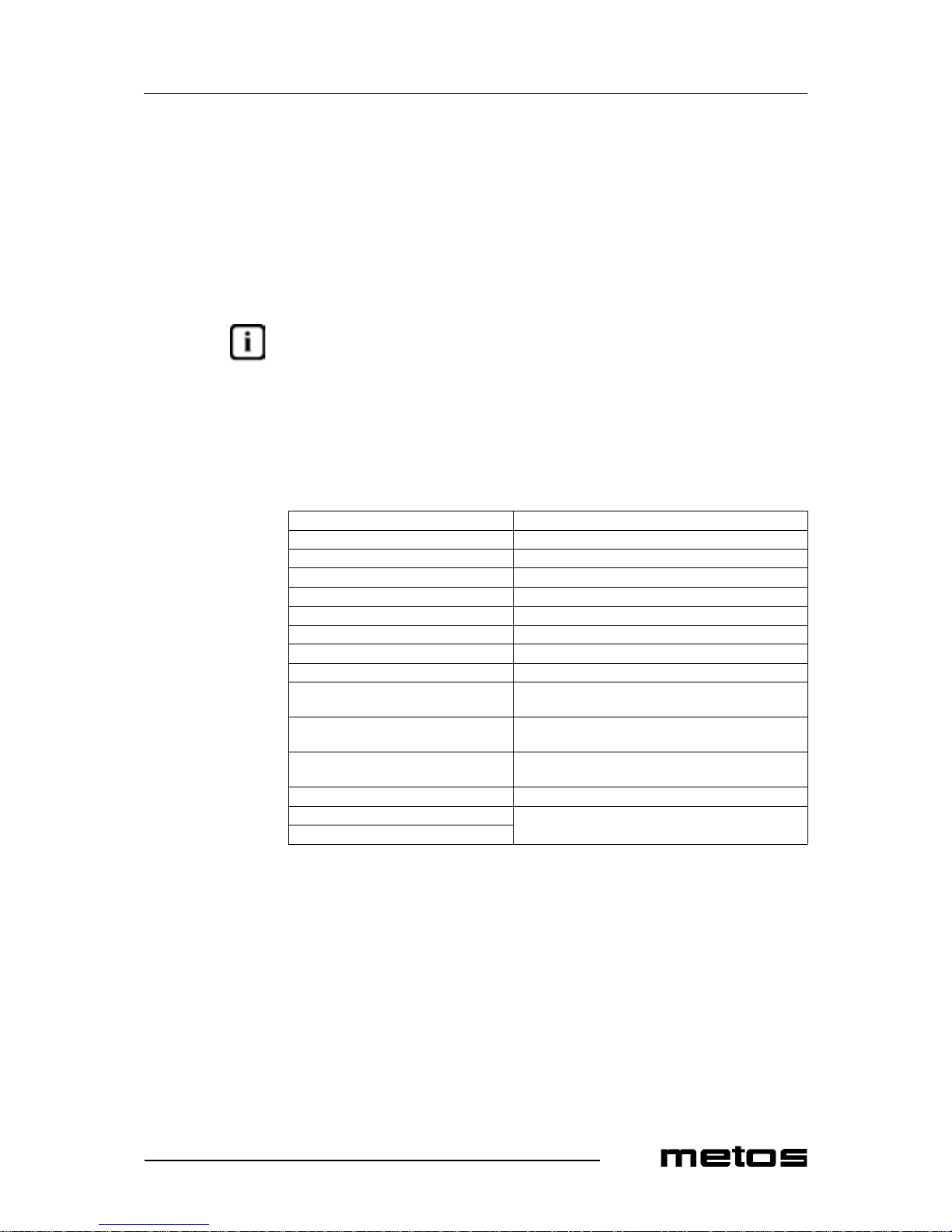
This appliance is designed to burn natural and liquid gas. To find out the category to
which this appliance belongs in the country where it is installed, please refer to the table
below.
Table 1: gas categories and pressure values
COUNTRY APPLIANCE CATEGORY GAS
RATED
PRESSURE
(mbar)
MINIMUM
PRESSURE
(mbar)
MAXIMUM
PRESSURE
(mbar)
Belgium France II2E+3+
G20 20 17 25
G25 25 17 30
G30 28 25 35
G31 37 25 45
Spain Grea t B ritain Ireland
Greece
II2H3+
G20 20 17 25
G30 28 25 35
G31 37 25 45
Italy Italian
Switzerland Portugal
II2H3+
G20 20 17 25
G30 30 25 35
G31 37 25 45
Austria German
Switzerland
II2H3B/P
G20 20 17 25
G30
50 42.5 57.5
G31
Germany II2ELL3B/P
G20
20 17 25
G25
G30
50 42.5 57.5
G31
Finland II2H3B/P
G20 20 17 25
G30
30 25 35
G31
Denmark II2H3B/P
G20 20 17 25
G30
30 25 35
G31
Sweden II2H3B/P
G20 20 17 25
G30
30 25 35
G31
Luxembourg I2E G20 20 17 25
Netherlands II2L3B/P
G25 25 20 30
G30
30 25 35
G31
Norway I3B/P
G30
30 25 35
G31
Hungary II2HS3B/P
G20
25 20 33
G25.1
G30
30 25 35
G31
Czech Republic II2H3B/P
G20 20 17 25
G30
30 25 35
G31

8.7.2004 Rev. 1.0
Installation
23
The appliance sho uld be conne cted to t he gas suppl y by means of metal pipes -- either rigid
or flexible-- hav ing an adequate diameter (see " Te chnical speci fications table" at the end
of this manual). When joining pipe fittings, never use oakum or Teflon as their residues
could get to the valve and jeopar dise its operation. Instead, inter pose a seal gasket su itable
for use in gas systems. Do not forge t to fit a shut off val ve on the gas suppl y lin e upstr eam
of the appliance, whi ch s hould be closed whenever the appliance is not in operation. Operating pressure values are shown on the rating plate and in "Table 1: gas categories and
pressure values" above.
After connecting the appliance to the gas system, check for leaks at joints and pipe fittings; to do so, use soapy water or a specific leak detector (spray).
5.12 Changing gas inlet connectio n from the right to the left (optional)
Gas inlet connection m ay be change d from the ri ght sid e to the le ft sid e using a kit which
includes the followi ng items:
• 1 Male/Female 1/2" elbow;
• Female/Female 1/2" elbow;
• Male/Male 1/2" pipe;
• kit fixing bracket.
To change the gas inl et connectio n from the righ t to the lef t side of th e appli ance, procee d
as follows:
• Fix th e FF el bo w to the gas r a m p o f th e applia n c e ;
• fix the MF elbow to the MM pipe;
• insert the pipe into the hole of the fixing bracket and fix it to the FF elbow;
• screw the bracket to the lower frame;
• proceed as usual to connect the appliance to the gas supply.

8.7.2004 Rev. 1.0
Installation
24
5.13 Checking gas supply pressure after installation
Gas supply pressure can be measured with a liquid-filled pressure gauge (for example, a
U-shaped pressure gauge, minimum subdivision 0.1 mbar) or a digital pressure gauge.
Proceed as follows:
• remove the rack, the bur ners and the right food-pan;
• unscrew the screw (item 3 in Fig. 9) on the pressure port (item 2);
Fig. 9
1. Ga s ramp
2. Pressure port
3. Pr essure po r t lo ck screw
• place the pressu re gauge;
• start up the applianc e following the instructions for use;
• check supply pressure;
• if the measured pressure value is within the range shown in "Table 1: gas categories and pressure values" furth er above, the applia nce can be started up. Otherwise,
contact the g as utility company;
• remove the pressur e gauge;
• replace the sealing screw (item 3);
• check for leaks (see the previous chapter 5.11 "Connecting gas supply").

8.7.2004 Rev. 1.0
Installation
25
5.14 Gas technical specifications
The appliance should be started up at its rated output with the nozzles shown in "Table 2:
burner specifications" below. All the necessary nozzles are provided in a small bag to-
gether with the appliance. The nozzles of the main burners are marked in hundredths of
mm, while those of pilot flames have a reference number.
Table 2: specifications for burners and nozzles
C D E Epot Oven
Rated power (kW) 3,5 5,6 7 10 8.5
Minimum output (kW) 1.3 2.2 3.8 3.8
Natural gas consumption (m³/h) G20 0,370 0,59 0.74 1.05 0.90
G25 0,43 0,69 0.86 1.23 1.05
G25.1 0,43 0,69 0.86 1.23 1.05
Liquid gas consumption (kg/h) 0,27 0,44 0.54 0.78 0.67
Town gas consumption (m³ /h) G110
G120
G20 20 mbar
Rated pressure (mbar) 20
Reduced pressure (mbar), minimum
Nozzles (1/100 mm) Pilot flame 35 35 35 35 27
Max. 140 170R 185R 240 255
Min. R R R R
Primary air di st ance (mm) 0 3 4 4 1
G25 20 mbar
Rated pressure (mbar) 20
Reduced pressure (mbar), minimum
Nozzles (1/100 mm) Pilot flame 35 35 35 35 27
Max. 150 185R 200R 265 245
Min. R R R R
Primary air di st ance (mm) 0 3 4 4 1
G25 25 mbar
Rated pressure (mbar) 25
Reduced pressure (mbar), minimum
Nozzles (1/100 mm) Pilot flame 35 35 35 35 27
Max. 140 170R 185R 255 225
Min. R R R R
Primary air di st ance (mm) 0 3 4 4 1
G30/31 28/37 mbar
G30/31 30 mbar
G30/31 30/37 mbar
Rated pressure (mbar) 28 / 30 / 37
Reduced pressure (mbar), minimum
Nozzles (1/100 mm) Pilot flame 20 20 20 20 19
Max. 90 115 130 155 145
Min. 45 65 80 80
Prima r y air dist an c e (m m ) 2,5 6 OPEN O P EN 2

8.7.2004 Rev. 1.0
Installation
26
* Apply the ai r regi ster p lat e (see chapte r "Repl acing oven burne r nozzles" in secti on "Ad-
justment instructions"). The primary air sleeve should be fitted and adjusted as shown in
"Table 2: burner specifications" above.
G30/31 50 mbar
Rated pressure (mbar) 50
Reduced pressure (mbar), minimum
Nozzles (1/100 mm) Pilot flame 20 20 20 20 19
Max. 80 105 115 140 130
Min. 45 65 80 80
Prima r y air dist an c e (m m ) 1,5 3 OPEN O P EN 2
G20 25 mbar
Rated pressure (mbar) 25
Reduced pressure (mbar), minimum /
Nozzles (1/100 mm) Pilot flame 35 35 35 35 27
Max. 130 160R 175 225 215
Min. R R R R
Primary air di st ance (mm) 0 3 4 4 1
G25.1 25 mbar
Rated pressure (mbar) 25
Reduced pressure (mbar), minimum /
Nozzles (1/100 mm) Pilot flame 35 35 35 35 27
Max. 150 180R 200R 265 245
Min. R R R R
Primary air di st ance (mm) 0 3 4 4 1
G110 8 mbar
Rated pressure (mba r)
Reduced pressure (mbar), minimum
Nozzles (1/100 mm) Pilot flame
Max.
Min.
Primary air di st ance (mm)
G120 8 mbar
Rated pressure (mba r)
Reduced pressure (mbar), minimum
Nozzles (1/100 mm) Pilot flame
Max.
Min.
Primary air di st ance (mm)
Table 2: specifications for burners and nozzles
C D E Epot Oven
8.7.2004 Rev. 1.0
Installation
27
5.15 Checking operation
1. Start u p the appl ia nce b y following t he i ns tructi ons g iven in chapt er "Usi ng the appliance";
2. check for gas leaks;
3. check for flame stability throughout the whole control range by going from high
to low.
5.16 Staff training
Inform all personnel a ssi gned to oper ate th e appli ance o n how to us e it by r eferrin g to t his
user’s manual and hand them out the manual.
5.17 Rating plate
The rating plate showing the specifications of the corresponding model is applied in the
position shown in the install ation and con nection draw ings and include s the data li sted below:
Manufacturer:
Model: (see front page)
Serial number:
Year of ma n uf actur e:
Category: (see "Technical specifications table")
Heatin g po w er: (see "Table 2: burner specifications" further above)
Natural gas consumpt ion: (see "Table 2: burner specifications" furt her above)
Liquid gas consumption: (see "Table 2: burner specifications" furt her above)
Supply pressure:
natural gases: G20
(see "Table 1: gas categories and pr essure values"
further above)
liquid gases (butane/propane): G 30/
G31
(see "Table 1: gas categories and pr essure values"
further above)
town gas: G110/G120
(see "Table 1: gas categories and pr essure values"
further above)
Gas inlet pipe size: (see "Technical specifications table")
Supply voltage:
(see the label on the packag ing and on the unit)
Appliance pre-set to use:

8.7.2004 Rev. 1.0
Adjustment instructions
28
6. Adjustment instructions
To convert (for example) from natural gas to liquid gas, you need to change the nozzles
of main and pilot burners. The appropriate nozzles are shown in "Table 2: burner speci-
fications""Table 3: burner specif ications".
6.1 Replacing the open fire burner nozzles
• Remove the rack, the wall baffle (item 1 in Fig. 10), the burner (item 2) and the
food-pan;
• loosen the fixing screw (item 5 in fig.10) of the air sleeve (item 2 in fig.10);
• unscrew the no zz le (it em 7) using a 13 mm wre nch and inst al l the appr opriate nozzle (as shown in "Table 2: specifications for burners and nozzles".
Fig. 10
1. Wall baffle
2. Burner
3. Venturi tube
4. Washer
5. Air sleeve fixing screw
6. Air sleeve ring
7. Nozzle
8. Metal ring
9. Nozzle holder
10. Washer
11. Screw
12. Nut
13. Bicone

8.7.2004 Rev. 1.0
Adjustment instructions
29
• adjust t he primary air di stance (H in Fig . 11) according to the values listed in "Ta ble 2: specif i c a tions fo r bu rners " .
Fig. 11
1. Air sleeve ring

8.7.2004 Rev. 1.0
Adjustment instructions
30
6.2 Replacing the open fire pilot flame nozzle
• Carry out the first step of the chapter 6.1;
• unscrew the seali ng screw (item 7 in Fig. 12) us ing a 11 mm wrench and remove it ;
• unscrew the nozzle (it em 6) using a screw-driver and remove it;
• install the appropriate nozzle and tighten it (see "Table 2: specifications for burners";
• adjust the pilot flame air by turning t he ring in item 4 in fig.12;
• the pilot flame will wrap around interely the thermocouple and its color will be
blue. Otherwise, check that the approp riate nozzles have been ins talled.
Fig. 12
1. Thermocouple fi xing nut
2. Pilot flame top
3. Thermocouple
4. Air sleeve ring
5. Pilot flame assembly
6. Nozzle
7. Sealing screw
8. Bicone union

8.7.2004 Rev. 1.0
Adjustment instructions
31
6.3 Replacing the oven burner nozzles [models with oven]
• Remove the bottom front panel (item 2 in Fig. 13) by unscrewing the screws in
item 2;
Fig. 13
1. Bottom front panel
2. Fixing screws
• unscrew the fixing screw (item 2 in Fig. 15) of the primary air sleeve (item 1 in
Fig. 15) and remove it;
• unscrew the nozzle (item 5 in Fig. 14) using a 13 mm wrench and install the appropriate nozzle (as shown in "Table 2: speci fications for burners" "Tabl e 3: specifications for burners");
Fig. 14
1. Union elbow
2. Lo ck nut
3. Nozzle
4. Burner

8.7.2004 Rev. 1.0
Adjustment instructions
32
• adjust the primary air distance (H in Fig. 15) according to the values listed in “Table 2: specifications for burners and nozzles”;
Fig. 15
1. Primary air sleeve
2. Fixing screw for the adjustment
H. Primary air adjustable distance

8.7.2004 Rev. 1.0
Adjustment instructions
33
6.4 Replacing the gas oven pilot flame nozzle
• Carry out the first 4 steps of the chapter 7.10 “Replacing the burner” below;
• place a 12 mm wrench on the pilot flame assembly (item 1 Fig. 16) to counterbalance any p ossible to r sion;
• using a 10 m m wrench, unscrew the fixing nut from the gas pipe (item 8 i n fig.16)
and remove it;
• remove the nozzle (item 4 in fig.16) from the pilot flame assembly and replace it
with the appropri ate nozzle (see "Table2: specifications for bur ners and nozzles”;
• follow the procedure in reverse to fix the new part;
• you do not need to adjust the primary air.
Fig. 16
1. Pilot flame assembly
2. Thermocouple
3. Ignition plug
4. Nozzle
5. Plug fixing nut
6. Thermocouple fi xing nut
7. Bicone
8. Gas pipe fixing nut

8.7.2004 Rev. 1.0
Adjustment instructions
34
6.5 Adjusting the minimum setting
To operate with liquid gases, remove the knobs, insert a screwdr iver and tighten the screw
in item 1 in Fig. 18.
Fig. 18
1. Screw for adjusting the minimum setting
2. Gas inlet union position
3. Thermocouple union position
4. Gas outlet uni on position
5. Pilot flame union position
For other types of gas, adjust the screw until the flame is stable and uniform, proceeding
as follows:
• unscrew the screw shown in ite m 1 in Fig. 19;
Fig. 19
1. Screw
• connect a liquid pressure gauge (for example, a U-shaped pressure gauge, minimum subdivision 0.1 mbar) or a digital pressure gauge;
• start up the appliance (as described in the instruction manual of the appliance).
The gas pressure with the burner ope rating on minimum must correspond to the pressure
values shown in “Table 2: specifications for burners and nozzles” under the entry “Reduced pressure (mbar), minimum”.

8.7.2004 Rev. 1.0
Adjustment instructions
35
6.6 Functional check
• Start the applianc e by following the "Operating instructions" ;
• check for leaks;
• check for flame stability throughout the ON- OFF-ON con trol range;
• check the lighting proc ess along t h e main burner and check that fl ames are even;
• check for proper operation of pilot flame;
• check that flue gase s come out of the corresponding pipes regularly;
• check that there is a good inflow of fresh air.

8.7.2004 Rev. 1.0
Troubleshooting
36
7. Troubleshooting
Users are not allowed to perform any maintenance operations on any parts of this appliance. Maintenance s hould be carried out by an authorized technician.
TROUBLE POSSIBLE CAUSES
MAINTENANCE
FOR THE USER
FOR THE TECHNICAL
SUPPORT SERVICE
OPEN FIRES
Pilot bu rn e r won ’ t
light:
pressure dr op i n gas supply pipe;
contact the gas utilit y company;
clogged nozzle;
remove the dirt from the no zzle;
gas valve damaged; replace it;
After releasing the
knob, the pilot burner
goes out:
valve knob has not held
down or it has he ld down
not enough time to al low
the thermocouple to get
hot;
repeat the ignition;
thermocouple faulty; replace it;
gas valve damaged; replace it;
Pilot flame stays lit, but
burner won’t li ght:
pressure dr op i n gas supply pipe;
contact the gas utilit y company;
clogged nozzle;
remove the dirt from the no z-
zle;
gas valve damaged; replace it;
gas outlet holes on the
burner cr ow n are
clogged;
clean the crown;
burner components are
not placed one over the
other correctly;
place them properly.
Turning th e fires ignition knob from max. to
min., th e b ur n er
switches off:
minimum leve l is too
low;
adjust th e m inimum level (see
chapte r “Adjusting the mi n i-
mum level” in the section “Ad-
justment instructions”).

8.7.2004 Rev. 1.0
Troubleshooting
37
TROUBLE POSSIBLE CAUSES
MAINTENANCE
FOR THE USER
FOR THE TECHNICAL
SUPPORT SERVICE
GAS OVEN
Pilot flame won’t light:
piezoele ctric ig nition de vice faulty;
replace it;
the igniti o n pl ug is not
secure ly fixed, or the
connection with the cable is wr on g;
check th e connection;
ignition plug insulator
damaged;
replace it;
pressure drop in gas supply pip e;
contact the gas utility company;
clogged nozzle;
remove the dirt from th e nozzle;
gas valve dam aged; replace it.
After re le as ing the
knob, the pilot flame
goes out
valve knob has not held
down or it has held down
not enough time to al low
the thermocouple to get
hot;
repeat the ignition;
thermocouple f au lty; repla ce it;
gas valve dam aged; replace it.
Pilot flam e stays lit, but
burner won’t light:
pressure drop in gas supply pip e;
contact the gas utility company;
clogged nozzle;
remove the dirt from th e noz-
zle;
gas valve dam aged; replace it;
gas outlet holes on the
burne r ar e clogged;
clean the burner.
The tem p er ature adjustm e nt doe s no t
work:
valve bulb is damaged; replace the valve;
thermocouple f au lty; repla ce the valve.
Uneven cooking (pronounced difference in
the product colouring):
temper ature is too high; lower the tem p erature;
pan is t oo cl ose to s ource
of heat;
lift the pan on the top guide;
different product size or
thickness;
in order to obtain an even co oking,
the product should be distributed
uniformly on each pan. In ca se of
solid food, the size, the layers and
the thickness must be as uniform as
possible;
non-horizontal rac ks;
level the appliance and check that
the racks are horizontal using the
adjust able feet : this operat ion is fu ndamental for an even cooking.

8.7.2004 Rev. 1.0
Troubleshooting
38
TROUBLE POSSIBLE CAUSES
MAINTENANCE
FOR THE USER
FOR THE TECHNICAL
SUPPORT SERVICE
ELECTRIC OVEN
No heating: no power;
check that the appliance
is energized;
The temperature adjustment does not wo rk
Operating thermostat
damaged
repl ac e it
A temperature is set but
the oven won't light:
safety th ermost at
tripped;
reset the thermostat.
Uneven cooking (pronounced difference in
the product colouring):
improper selector position or position not suitable to the type of
cooking;
place the s elect or s o tha t
heat is gener ated by both
the bottom and t he top of
the oven according to
the type of cookin g to be
performed;
different product size or
thickness;
in order to obtain an
even cooking, the product should be di stribut ed
uniformly on each pan.
In case o f sol i d f ood, th e
size, the layers and the
thickness mus t be a s un iform as possible;
non-horizontal racks;
level th e appliance and
check that the racks are
horizontal using the ad justable feet: this operation is fundamental for
an even cooking;
one of the two heating
elements is faulty;
repl ac e it .
TROUBLE
POSSIBLE
CAUSES
MAINTENANCE
FOR THE USER
FOR THE TECHNI-
CAL SUPPORT
SERVICE
HOT CABINET
No heating: no power;
check that the appliance
is energized.
A temperature is set but
the cabin et won't light:
thermostat faulty; replace it;
heating element break; replace it.

8.7.2004 Rev. 1.0
Technical specifications
61
9. Technical specifications
Wiring diagra ms................................ ...
Installation and connection drawings.
Technical specifications table..............

6SC00476: wirin g diagram 96/04 CGEE, 96/04 CGEE2P, 96/ 04 CGEEP - 3/N/P E ~4 00V 50-60 Hz

8.7.2004 Rev. 1.0
Technical specifications
63
6LE00443: legend of the wiring diagram 6SC00476
Letter code Codes Descriptions Specifications
E55 826620031 Heating element 700W - 230V
E56-57-5 8-59 8266 20041 Heating element 1500W - 230V
B2 826630123 Control thermostat 50 -300°C - 3F
B16 826630130 Safety thermost at 360°C - 3F
S5-B1 826630230 Switch-Cont rol thermostat 30 - 90°C - 1F
E1 A038506 Line pilot lamp 400V - 150°C
E15 A038506 Operation pilot lamp 400V - 150°C
E16 A038506 Operation pilot lamp 400V - 150°C
S6 A046001 Switch 3F
S7 A046750 Switc h 4 positions

6SC00477: wiring diagram 94/04CGE, 94/04CGE1P, 94/04CGEP 3/N/PE ~400V 50-60 Hz

8.7.2004 Rev. 1.0
Technical specifications
65
6LE00441: legend of the wiring diagram 6SC00477
Letter code Codes Descriptions Specifications
E56-57-58-59 826620041 Heating elemen t 1500W - 230V
B2 826630 123 Control thermost at 50 - 300°C
B16 826630130 Safety thermostat 360°C - 3F
E1 A038506 Line pilot lamp 400V - 150°C
E16 A038506 Operation pilot lamp 400V - 150°C
S6 A046001 Switch 3F
S7 A046750 Switch 4 positions

6SC00478: wiring diagram 94/04CGGE, 94/04CGEE1P,94/04CGEEP 3/N/PE ~400V 50-60 Hz

8.7.2004 Rev. 1.0
Technical specifications
67
6LE00442: legend of the wiring diagram 6SC00478
Letter code Codes Descriptions Specifications
E55 826620031 Heating element 700W - 230V
S5-B1 826630230 Switch-Cont rol thermostat 30 - 90°C - 1F
E15 A038506 Operation pilot lamp 400V - 150°C

6SC00480: wiring diagram 98/04CGE, 98/04CGE2P , 98/04CGEP - 1/N/PE ~230V 50-60 Hz

8.7.2004 Rev. 1.0
Technical specifications
69
6LE00480: legend of the wiring diagram 6SC00480
Letter code Codes Descriptions Specifications
E56-57-58-59-60-61-62-63 826620041 Heating element 1500W - 230V
B2-3 826630123 Control thermostat 50 - 300°C - 3f
B16-17 826630130 Safety thermostat 360°C - 3F
E1-2 A038506 Line pilot lam p 400V - 150°C
E16-17 A038506 Operation pi lot lamp 400V - 150°C
S6-8 A046001 Switch 3F
S7-9 A046750 Switch 4 positions

8.7.2004 Rev. 1.0
Technical specifications
70
Installation and connection drawi ng 92/04TCG, 92/04TCG1P, 92/04TCGP
Description
A Connecting gas supply
B Distance between feet
C Distance between burners
E Rating plate
F Connecting electric oven
G Connecting hot cabinet

8.7.2004 Rev. 1.0
Technical specifications
71
Installation and connection drawi ng 94/04TCG, 94/04TCG1P, 94/04TCGP
Description
A Connecting gas supply
B Distance between feet
C Distance between burners
E Rating plate
F Connecting electric oven
G Connecting hot cabinet

8.7.2004 Rev. 1.0
Technical specifications
72
Installation and connection drawi ng 96/04TCG, 96/04TCG2P, 96/04TCGP
Description
A Connecting gas supply
B Distance between feet
C Distance between burners
E Rating plate
F Connecting electric oven
G Connecting hot cabinet

8.7.2004 Rev. 1.0
Technical specifications
73
Installation and connection drawi ng 98/04TCG, 98/04TCG2P, 98/04TCGP
Description
A Connecting gas supply
B Distance between feet
C Distance between burners
E Rating plate
F Connecting electric oven
G Connecting hot cabinet

8.7.2004 Rev. 1.0
Technical specifications
74
Installation and connection drawi ng 92/04CG, 92/04CG1P, 92/04CGP
Description
A Connecting gas supply
B Distance between feet
C Distance between burners
E Rating plate
F Connecting electric oven
G Connecting hot cabinet

8.7.2004 Rev. 1.0
Technical specifications
75
Installation and connection drawi ng 94/04CG, 94/04CG1P, 94/04CGP
Description
A Connecting gas supply
B Distance between feet
C Distance between burners
E Rating plate
F Connecting electric oven
G Connecting hot cabinet

8.7.2004 Rev. 1.0
Technical specifications
76
Installation and connection drawi ng 96/04CG, 96/04CG2P, 96/04CGP
Description
A Connecting gas supply
B Distance between feet
C Distance between burners
E Rating plate
F Connecting electric oven
G Connecting hot cabinet

8.7.2004 Rev. 1.0
Technical specifications
77
Installation and connection drawi ng 98/04CG, 98/04CG2P, 98/04CGP
Description
A Connecting gas supply
B Distance between feet
C Distance between burners
E Rating plate
F Connecting electric oven
G Connecting hot cabinet

8.7.2004 Rev. 1.0
Technical specifications
78
Installation and connection drawing 94/04CGG, 94/04CGG1P, 94/04CGGP
Description
A Connecting gas supply
B Distance between feet
C Distance between burners
E Rating plate
F Connecting electric oven
G Connecting hot cabinet

8.7.2004 Rev. 1.0
Technical specifications
79
Installation and connection drawi ng 94/04CGE, 94/04CGE1P, 94/04CGEP
Description
A Connecting gas supply
B Distance between feet
C Distance between burners
E Rating plate
F Connecting electric oven
G Connecting hot cabinet

8.7.2004 Rev. 1.0
Technical specifications
80
Installation and connection drawing 96/04CGG, 96/04CGG2P, 96/04CGGP
Description
A Connecting gas supply
B Distance between feet
C Distance between burners
E Rating plate
F Connecting electric oven
G Connecting hot cabinet

8.7.2004 Rev. 1.0
Technical specifications
81
Installation and connection drawing 96/04CGGE, 96/04CGGE2P, 96/04CGGEP
Description
A Connecting gas supply
B Distance between feet
C Distance between burners
E Rating plate
F Connecting electric oven
G Connecting hot cabinet

8.7.2004 Rev. 1.0
Technical specifications
82
Installation and connection drawi ng 96/04CGE, 96/04CGE2P, 96/04CGEP
Description
A Connecting gas supply
B Distance between feet
C Distance between burners
E Rating plate
F Connecting electric oven
G Connecting hot cabinet

8.7.2004 Rev. 1.0
Technical specifications
83
Installation and connection draw ing 96/04CGEE, 96/04CGEE2P, 96/04CGEEP
Description
A Connecting gas supply
B Distance between feet
C Distance between burners
E Rating plate
F Connecting electric oven
G Connecting hot cabinet

8.7.2004 Rev. 1.0
Technical specifications
84
Installation and connection drawing 98/04CGG, 98/04CGG2P, 98/04CGGP
Description
A Connecting gas supply
B Distance between feet
C Distance between burners
E Rating plate
F Connecting electric oven
G Connecting hot cabinet

8.7.2004 Rev. 1.0
Technical specifications
85
Installation and connection drawi ng 98/04CGE, 98/04CGE2P, 98/04CGEP
Description
A Connecting gas supply
B Distance between feet
C Distance between burners
E Rating plate
F Connecting electric oven
G Connecting hot cabinet

8.7.2004 Rev. 1.0
Technical specifications
86
Item Type Voltage Specification
Internal dimensions gas oven 94GG,96GG,96GGE,98GG,94GG1P,96GG2P,96GGE2P,
98GG2P,94GGP,96GGP,96GGEP,98GGP
536 x 699 x 290 m m
Internal dim ensions elec tric oven 94GE,96GE,96G EE,98GE,94GE1P,96GE2P,96GEE2P,9
8GE2P,94GEP,96GEP,96GEEP,98GEP
536 x 699 x 260 m m
Inner cupboard dimensi ons 96GG,96GE,96GG 2P,96GE2 P,9 6GGP, 96GEP 346 x 730 x 402 m m
Internal dimens ions hot cupboar d 96GGE, 96GEE,96GGE2P, 96GEE2P,96 GGEP, 96GEEP 330 x 730 x 3 30 mm
Volume with pac kage 92G,92G1P,92GP 0,54 m³
Volume with package 94G,94GG,94GE,94G1P,94GG1P,94GE1P,94GP,94GGP
,94GEP
1,02 m ³
Volume with package 96G,96GG,96GGE,96GE,96GEE,96G2P,96GG2P,96GG
E2P,96GE2P,96GEE2P,96GP,96GGP,96GGEP,96GEP,9
6GEEP
1,45 m ³
Volume with package 98G,98GG,98GE,98G2P,98GG2P,98GE2P,98GP,98GGP
,98GEP
1,93 m ³
Volume with package 92TG,92TG1P,92TGP 0,26 m³
Volume with package 94TG,94TG1P,94TGP 0,48 m ³
Volume with package 96TG,96TG1P,96TGP 0,71 m³
Volume with package 98TG,98TG1P,98TGP 0,93 m ³
Total wei ght 92G,92G1P,92GP 70 kg
Total weight 94G,94G1P,94GP 116 kg
Total wei ght 96G,96G1P,96GP 157 kg
Total weight 98G,98G1P,98GP 198 kg
Total wei ght 94GG,94GG1P,94GGP 180 kg
Total weight 94GE,94GE1P,94GEP 175 kg
Total wei ght 96GG,96GG2P,96GGP 250 kg
Total weight 96GGE,96GGE2P,96GGEP 253 kg
Total wei ght 96GE,96GE2P,96GEP 249 kg
Total weight 96GEE,96GEE2P,96GEEP 252 kg
Total wei ght 98GG,98GG2P,98GGP 330 kg
Total weight 98GE,98GE2P,98GEP 320 kg
Total wei ght 92TG,92TG1P,92TGP 46 kg
Total weight 94TG,94TG1P,94TGP 88 kg
Total wei ght 96TG,96TG1P,96TGP 123 kg
Total weight 98TG,98TG1P,98TGP 160 kg
Electric oven power 94GE,96GE,96GEE,94GE1P,96GE2P, 96GEE2P,94GEP,
96GEP,96GEEP
6 kW
Electric oven power 98GE,98GE2P,98GEP 6 kW x 2
Electric cupboard power 96GGE,96GEE,96GGE2P,96GEE2P,96GGEP,96GEEP 0,7 k W

8.7.2004 Rev. 1.0
Technical specifications
87
Rated output 94GE,96GE,94GE2P,96GE2P,94GEP,96GEP 6 kW
Rated output 96GGE,96GGE2P,96GGEP 0,7 kW
Rated output 96GEE,96GEE2P,96GEEP 6,7 kW
Rated output 98GE,98GE2P,98GEP 6 kW x 2
Max. current 94GE,96GE,94GE1P,96GE2P,94GEP,96GEP A 13,05 A
Max. current 94GE,96GE,94GE1P,96GE2P,94GEP,96GEP H 1 7,26 A
Max. current 96GGE,96GGE2P,96GGEP P 3,05 A
Max. current 96GEE,96GEE2P,96GEEP A 13,05 A
Max. current 96GEE,96GEE2P,96GEEP H 20,31 A
Max. current 98GE,98GE2P,98GEP A 13,05 A x 2
Max. current 98GE,98GE2P,98GEP H 17,26 A x 2
Cable cross section 94GE,96GE,94GE1P,96GE2P,94GEP,96GEP A 5 x 1,5 mm²
Cable cross section 94GE,96GE,94GE1P,96GE2P,94GEP,96GEP H 4 x 2,5 mm ²
Cable cross section 96GGE,96GGE2P,96GGEP P 3 x 1,5 mm²
Cable cross section 96GEE,96GEE2P,96GEEP A 5 x 1,5 mm²
Cable cross section 96GEE,96GEE2P,96GEEP H 4 x 4 mm²
Cable cross section 98GE,98GE2P,98GEP A 5 x 1,5 mm² x 2
Cable cross section 98GE,98GE2P,98GEP H 4 x 1,5 mm² x 2
Supply voltag e 94GE,96GE,96G EE,98GE,94GE2P, 96G E2P,96GEE2P,9
8GE2P,94GEP,96GEP,96GEEP,98GEP
A 3/N/PE~400V 50
Hz
Supply voltage 94GE,96GE,96GEE,98GE,94GE2P,96GE2P,96GEE2P,9
8GE2P,94GEP,96GEP,96GEEP,98GEP
H 3/PE~230V 50 Hz
Supply voltage 96GGE,96GGE2P,96GGEP P 1/N/PE~230V 50
Hz
Gas burnes 92G,92TG 1 x 3,5 kW
Gas burnes 92G,92TG 1 x 7 kW
Gas burnes 94G,94TG,94GG,94GE 1 x 3,5 kW
Gas burnes 94G,94TG,94GG,94GE 2 x 5,6 kW
Gas burnes 94G,94TG,94GG,94GE 1 x 7 kW
Gas burnes 96G,96TG,96GG,96GE,96GGE,96GEE 2 x 3,5 kW
Gas burnes 96G,96TG,96GG,96GE,96GGE,96GEE 2 x 5,6 kW
Gas burnes 96G,96TG,96GG,96GE,96GGE,96GEE 2 x 7 kW
Gas burnes 98G,98TG,98GG,98GE 2 x 3,5 kW
Gas burnes 98G,98TG,98GG,98GE 4 x 5,6 kW
Gas burnes 98G,98TG,98GG,98GE 2 x 7 kW
Gas burnes 92G1P,92TG1P 1 x 3,5 kW
Gas burnes 92G1P,92TG1P 1 x 10 Kw
Gas burnes 94G1P,94TG1P,94GG1P,94GE1P 1 x 3,5 kW
Gas burnes 94G1P,94TG1P,94GG1P,94GE1P 2 x 5,6 kW
Gas burnes 94G1P,94TG1P,94GG1P,94GE1P 1 x 10 kW
Gas burnes 96G2P,96TG2P,96GG2P,96GE2P,96GGE2P,96GEE2P 2 x 3,5 kW
Gas burnes 96G2P,96TG2P,96GG2P,96GE2P,96GGE2P,96GEE2P 2 x 5,6 kW
Gas burnes 96G2P,96TG2P,96GG2P,96GE2P,96GGE2P,96GEE2P 2 x 10 kW
Item Type Voltage Specification

8.7.2004 Rev. 1.0
Technical specifications
88
Gas burnes 98G2P,98TG2P,98GG2P,98GE2P 2 x 3,5 kW
Gas burnes 98G2P,98TG2P,98GG2P,98GE2P 4 x 5,6 kW
Gas burnes 98G2P,98TG2P,98GG2P,98GE2P 2 x 10 kW
Gas burnes 92GP,92TGP 2 x 10 kW
Gas burnes 94GP,94TGP,94GGP,94GEP 4 x 10 kW
Gas burnes 96GP,96TGP,96GGP,96GEP,96GGEP,96GEEP 6 x 10 kW
Gas burnes 98GP,98TGP,98GGP,98GEP 8 x 10 kW
Heat gas oven 94GG,96GG,96GGE,94GG1P,96GG2P,96GGE2P,94GG
P,96GGP,96GGEP
8,5 kW
Heat gas oven 98GG,98GG2P,98GGP 8,5 kW x 2
Gas power 92G,92TG 10,5 kW
Gas power 94G,94TG,94GE 21,7 kW
Gas power 96G,96TG,96GE,96GEE 32,2 kW
Gas power 98G,98TG,98GE 43,4 kW
Gas power 94GG 30,2 kW
Gas power 96GG,96GGE 40,7 kW
Gas power 98GG 60,4 kW
Gas power 92G1P,92TG1P 13,5 kW
Gas power 94G1P,94TG1P,94 G E 1P 24,7 kW
Gas power 96G2P,96TG2P,96GE2P,96GEE2P 38,2 kW
Gas power 98G2P,98TG2P,98 G E 2P 49,4 kW
Gas power 94GG1P 33,2 kW
Gas power 96GG2P,96GGE2P 46,7 kW
Gas power 98GG2P 66,4 kW
Gas power 92GP, 92TGP 20 kW
Gas power 94GP,94TGP,94GEP 40 kW
Gas power 96GP, 96TGP,96GEP,96GEEP 60 kW
Gas power 98GP,98TGP,98GEP 80 kW
Gas power 94GGP 48,5 kW
Gas power 96GGP,96GGEP 68,5 kW
Gas power 98GGP 97 kW
Air requirement for combustion 92G, 92TG 21 m³/ h
Air requirement for combustion 94G,94TG,94GE 43,4 m³/h
Air requirement for combustion 96G, 96TG,96GE,9 6G EE 64,4 m³/h
Air requirement for combustion 98G,98TG,98GE 86,8 m³/h
Air requirement for com bustion 94GG 60,4 m³/h
Air requirement for combustion 96GG,96GGE 81,4 m ³/h
Air requirement for combustion 98GG 120,8 m³/h
Air requirement for combustion 92G1P,92TG1P 27 m³/h
Air requirement for combustion 94G1P,94TG1P,94 G E 1P 49,4 m³/h
Air requirement for combustion 96G2P,96TG2P,96GE2P,96GEE2P 76,4 m³ /h
Air requirement for combustion 98G2P,98TG2P,98 G E 2P 98,8 m³/h
Air requirement for combustion 94GG1P 66,4 m ³/h
Item Type Voltage Specification

8.7.2004 Rev. 1.0
Technical specifications
89
92G=92/04 CG, 92 TG=92/04 TCG, 94G=94/04 CG, 94TG=94/0 4 TC G, 94GG=94/04 CGG, 94GE=94/04 CGE, 96G=96/
04 CG, 96TG=96/04 TCG, 96GG=96/04 CGG, 96GGE=96/04 CGGE, 96GE=96/04 CGE, 96GEE=96/04 CGE, 98G=98/
04 CG, 98TG=98/04 TCG, 98GG=98/04CGG, 98GE=98/04 CGE, 92G1P=92/04 CG1P, 92TG1P=92/04 TCG1P,
94G1P=94/04 CG1P, 94TG1P=94/04 TCG1P, 94GG1P=94/04 CGG1P, 94GE1P=94/04 CGE1P, 96G2P=96/04 CG2P,
96TG2P=96/04 TCG2P, 96GG2P=96/04 CGG2P, 96GGE2P=96/04 CGGE2P, 96GE2P=96/04 CGE2P, 96GEE2P=96/04
CGEE2P, 98G1P=98/04 CG2P, 98TG1P=98/04 TCG2P, 98GG2P=98/04CGG2P, 98GE2P=98/04 CGE2P, 92TGP=92/04
TCGP, 92GP=92/04 CGP, 94GP=94/04 CGP, 94TGP=94/04 TCGP, 94GGP=94/04 CGGP, 94GEP=94/04 CGEP,
96GP=96/04 CGP, 96TGP=96/04 TCGP, 96GGP=96/04 CGGP, 96GGEP=96/04 CGGEP, 96GEP=96/04 CGEP,
96GEEP=96/04 CGEEP, 98GP=98/04 CGP, 98TGP=98/04 TCGP, 98GGP=98/04CGGP, 98GEP = 98/04 CGEP
A=3/N/PE∼400/230V 50Hz, H=3/PE∼230V 50Hz, P= 1/N/PE~220 -240V 50Hz
Air requirement for combustion 96GG2P,96GGE2P 93,4 m³/h
Air requirement for combustion 98GG2P 132,8 m³/h
Air requirement for combustion 92GP, 92TGP 40 m³/h
Air requirement for combustion 94GP,94TGP,94GEP 80 m³/h
Air requirement for combust ion 96GP,96 TGP,96GEP,96GE EP 1 20 m ³/h
Air requirement for combustion 98GP,98TGP,98GEP 160 m³/h
Air requirement for combustion 94GGP 97 m³/h
Air requirement for combustion 96GGP,96GGEP 137 m³/h
Air requirem ent for com bustion 98GGP 194 m³/h
Constructi on type A
Gas inlet 3/4" GC ISO R7
Item Type Voltage Specification

 Loading...