

Page 1
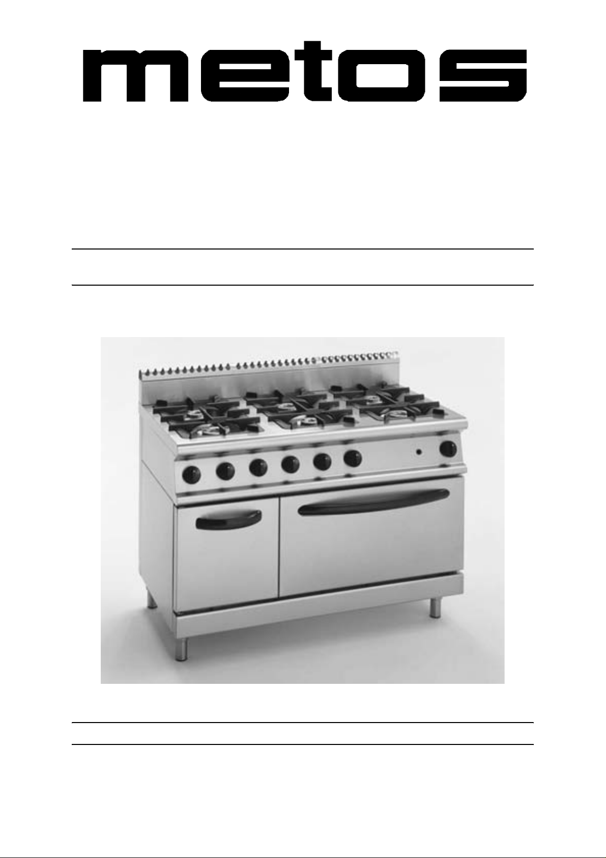
GAS RANGES
700 - Restaurant Series
TYPE: 72/02CG, 72/02TGC, 74/02CG, 74/02TGC, 76/02CG, 76/02TGC, 74/02CGG, 74/
02CGE, 76/02CGG, 76/02CGGE, 76/02CGE, 76/02CGEE, 76/02CGFL
Installation and Operation Manual
S/N: Rev.: 1.0
Page 2

Page 3

30.7.2003 Rev. 1.0
Dear C us to me r ,
Congratulations on deciding to choose a Metos app liance for your kitchen activities. You
made an excellent choice. We will do our best to make you a satisfied Metos customer
like thousands of customers we have around the world.
Please read this manual carefully. You will learn correct, safe and efficien t working methods in order to get the best possibl e benefit from the appl iance. Th e instr uctions and hints
in this manual will give you a quick and easy start, and you will soon note how nice it is
to use the Metos equipment.
All rights are reserved for technical changes.
You will find the main te chnical da ta on the rating plate fixed to the equipment . When you
need service or technical help, please let us know the serial number shown on the rating
plate. This will make it easier to provide you with corr ect service.
For your convenienc e, spa ce is provide d be low for you to r ec ord your lo cal Me tos s ervic e
contact information.
METOS TEAM
Metos service phone number:...............................................................................................
Contact person:....................................................................................................................
Page 4

30.7.2003 Rev. 1.0
Page 5

30.7.2003 Rev.
1. General information ..................................................................................... 1
1.1 Sym b o l s us ed in the manu a l ...... ............................................. ....................................... 1
1.2 Sym b o l s us ed o n th e a p p l i a n ce ................................................... ................................... 1
1.3 Checking correspondence between the appliance and the manual . ............................... 2
2. Safety .............................................................................................................. 3
2.1 Using t h e ap p liance safely . .............. .............................................................................. 3
2.2 Saf et y in structi o n s i n ca se o f m al functi on .......................................... ........................... 3
2.3 Additional prohibitions (hazardous procedures) ........................................................... 3
2.4 Disposing of the appliance ............................................................................................ 3
3. Functional description .................................................................................. 5
3.1 Appl i c ation of t h e app l i a n ce .. ....................................... ................................................. 5
3.1.1 Prohibited use ........................................................................................................ 5
3.2 Construction .................................................................................................................. 5
3.2.1 Construction features ............................................................................................. 5
3.2.2 Cooking surfaces .................................................................................................... 6
3.2.3 Gas ov e n s ........ ................................................... ................................................... 6
3.2.4 Electric ovens ......................................................................................................... 7
3.2.5 Hot cupboard .......................................................................................................... 7
4. Operating instructions ................................................................................. 9
4.1 Befo r e u si n g the a p p l i a n ce ...... ............................................. ......................................... 9
4.1.1 Prep aring the ap p liance f o r u se ......................................... ..................................... 9
4.2 Using t h e ap p liance ..... .......................... ...................................................................... 10
4.2.1 Operating controls ............................................................................................... 10
4.2.2 Turning the open burners on and off ................................................................... 11
4.2.3 Turning on the gas oven ....................................................................................... 12
4.2.4 Turning on the electric oven ................................................................................ 13
4.2.5 Turning on the hot cupboard ................................................................................ 14
4.2.6 Safe t y t h e rmo stat ..... .................... ........................................................................ 14
4.2.7 Preheating ............................................................................................................ 14
4.3 After-use care .............................................................................................................. 15
4.3.1 Cleani n g ................ .................... .............. ................... .............. .................... ........ 15
4.3.2 Idle period ............................................................................................................ 16
4.3.3 Peri o d i c m a i n tenance ........................................................................................... 16
Page 6

30.7.2003 Rev.
5. Install a ti o n ............. ................ ................. ................ ................. ................ .... 17
5.1 General info rmatio n ................... .................................................................................. 17
5.1.1 Regulatory installation conditions ....................................................................... 17
5.2 Exhausting fumes ........................................................................................................ 17
5.3 Possible environmental interference ............................................................................ 18
5.4 Pre p ari n g fo r instal l a t i o n . ..................................................................... ....................... 18
5.5 Storage ........ .............. .................... .............. ................... .............. .................... ............ 18
5.6 Transporting the appliance .......................................................................................... 18
5.7 Unpacking the appliance ............................................................................................. 18
5.8 Disposing of packaging materials ............................................................................... 18
5.9 Positioning the appliance ............................................................................................. 19
5.10 Electrical connections (versions with electric oven and/or hot
cupboard) .......... .......... .......... .......... .......... .......... ................... .......... .......... .......... ........... 19
5.10.1 General information ........................................................................................... 19
5.10.2 Connecting a type "Y" power cord to the app l i a n c e’s termin al block ............... 20
5.11 Gas supply connection ............................................................................................... 22
5.12 Checking gas supply pressure after installation ....................................................... 24
5.13 Gas technical specifications ...................................................................................... 25
5.14 Checking operation .................................................................................................... 27
5.15 Staff training .............................................................................................................. 27
5.16 Rating plate ................................................................................................................ 27
6. Adjustment instructions ............................................................................. 29
6.1 Rep la c i n g ope n b u rner nozzl e s ............................................... ..................................... 30
6.2 Rep la c i n g the n o z zl e o f o p en burner pil o t fl a m es ........ ............................................... 32
6.3 Rep la c i n g ove n b u rner nozzl e s ............................................... ..................................... 33
6.4 Replacing the nozzle of the oven pilot flame .............................................................. 35
6.5 Adju st i n g minimum o u tpu t .................. ........................................................................ 36
6.6 Functional check .......................................................................................................... 37
7. Troubleshooting .......................................................................................... 39
9. Technical specifications .............................................................................. 69
Page 7
General information
1. General information
Read the inst ru ctio ns in t his m an ual ca refu lly , a s the y c ont ain im port ant inf or ma tio n on
how to install, use and servi ce the appliance safely, properly, and effectively.
Keep this manual in a safe place so that it can be used as reference by other operators of
the app liance.
This appliance s hould be i nsta lled fol lowi ng th e instruc tio ns provi ded b y the manufa cturer and in compliance with all applicable local regulations. This appliance should be connected to the power and gas supply by qualified personnel only.
All personnel in charge of u si ng this appliance should be specificall y trained in its operation.
2.9.2003 Rev. 1.0
In the event of failure or malfunction, switch off the appliance. The periodic functional
checks requeste d in this manual s hould be carried out ac cording to the instructions. Have
the appliance ser viced by a technically qualified person duly autho r ized by the manufacturer that uses genuine spare parts.
Failure to comply with the above may jeopardise the appliance’s safety.
1.1 Symbols used in the manual
This symbol inf orms abo ut a situa tion where a sa fety ri sk c oul d be i mminent . The ins tructions provided are ma ndatory in order to prevent inj ury.
This symbol inform s about the right way to act in order to prevent bad re s ults, damage to
the appliance, or hazardous situations.
This symbol informs about tips and hints that help the user get the best performance out
of the appliance.
This symbol informs about a function that should be taken into account for self-control
purposes.
1.2 Sy mbols used on the appliance
This symbol on a part warns the user that there are electrical terminals behind it. Therefore, this part should be removed by qualified personnel only.
1
Page 8

2.9.2003 Rev. 1.0
General information
1.3 Checking correspondence between the appliance and the manual
The rating plate of the appl iance shows its serial number. If the manuals ar e missing, you
may order new ones from the manufacturer or your local representative. When ordering
new manuals it is essential to quote the serial number shown on the rati ng plate.
2
Page 9

Safety
2. Safety
2.1 Using the appliance safely
Being an appliance designed only for professional use , it should be operated by qualified
personnel exclusively. Never leave the appliance unattend ed while it is on.
Do not move the appliance while hot.
2.2 Safety instructions in case of malfunction
2.9.2003 Rev. 1.0
If the appliance will remain idle for some time or in the event of a failure, abnormal operation, etc., turn off the shutoff valve upstream of the appliance and disconnect it from
power supply. Call the service.
2.3 Addition al prohibitions (ha z ardous procedures)
Never tamper with the seals of the adjusting screws located on the gas valves.
2.4 Disposing of the appliance
This appliance has been manufactured using recyclable raw materials and does not contain any hazardous or toxic substances. To dispose of the appliance and all its packaging
materials, strictly follow the local regulations in force in the place where it is installed.
Packaging materials should be divided according to the type and delivered to a specific
collection site. Ensure compliance with environmental protection regulations.
3
Page 10

Safety
2.9.2003 Rev. 1.0
4
Page 11

Functional description
3. Functional description
3.1 Application of the applian ce
The appliance is designed for use in the gastronomy and confectionery industrie s only.
3.1.1 Prohibited use
The manufacturer cannot be held liable for any faults caused by defective installation or
inappropriate use of the appliance. In such ca se s, the warranty shall be null and void.
2.9.2003 Rev. 1.0
3.2 Construction
3.2.1 Construction features
Supporting structure made of galvanized steel.
Exterior finish and height-adjustable feet are stainless steel type AISI 18/10.
Control panels are con veniently shaped and have controls slanted towards the operator.
5
Page 12
Functional description
3.2.2 Cooking surfaces
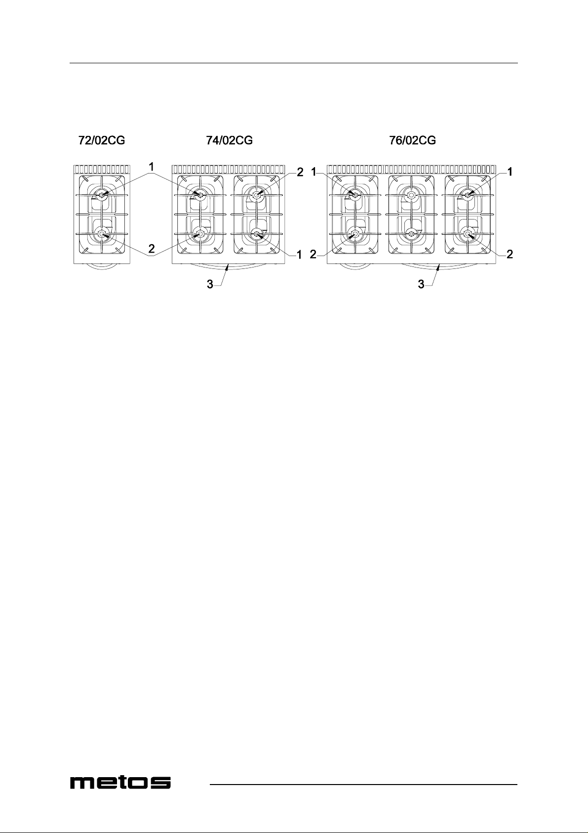
Fig. 1
2.9.2003 Rev. 1.0
1. Burner rated 3.5 kW (open burners)
2. Burner rated 5.6 kW (open burners)
3. Burner rated 7.9 kW (oven)
3.2.3 Gas ovens
• Unit with 2, 4 o r 6 stabi lis ed-flame gas burners made of nic kel-pl ated cast ir on a nd
controlled by pilot flames;
• burner type:double-crown burner rated 3.5 kW (item 1 in Fig. 1) double-crown
burner rated 5.6 kW (item 2 in Fig. 1);
• high-to-l ow output control (Fig. 3 further below);
• safety valves fitted with thermocouple ensure that gas flow will be immediately
shut off in the event that a burner is extinguished accident ally or a failure occurs;
• two-burner acid-resistant black en amelled cast-iron grate s;
• stainless steel drip pans.
• Stainles s stee l GN 2/1 s tati c oven wit h tempe rat ure ad justa ble fr om 50°C to 300 °C
(122°F to 572°F );
• tubular steel burner rated 7.9 kW (item 3 in Fig. 1) with self-stabilis ing flame;
• piezoelectric ignition of pilot flame;
• safe ty valv e fit ted wi th th ermoc oupl e ensu res th at ga s flo w will be im medi ately
shut off in the event that a burner is extinguished accident ally or a failure occurs;
• wire shelf support with two loading posit ions and a device to prevent tipping;
• removable, high-radiance, ribbed cast-iron bottom pla tes;
• silicone rubber oven door gasket, easily replaceable.
6
Page 13

Functional description
3.2.4 Electric ovens
• Stainles s stee l GN 2/1 s tati c oven wit h tempe rat ure ad justa ble fr om 50°C to 300 °C
• two sheathed heating units (top and bottom) separately adjustable through a selec -
• safety thermo stat to prevent over h eating;
• knobs with watertight gasket;
• wire shelf support with two loading posit ions and a device to prevent tipping;
• removable sta inless steel bot tom plate;
• silicone rubber oven door gasket, easily replaceable.
3.2.5 Hot cupboard
• Heating provided by a sheathed heating element placed at the bottom of the cup-
• hot cupboard temperature adjustable from 50°C to 90°C (122°F to 194°F);
• perforated stainless middle shelf, removable and adjustable to two heights;
• interior size GN 2/1.
2.9.2003 Rev. 1.0
(122°F to 572°F );
tor switch and controlled by a single thermostat;
board;
7
Page 14

Functional description
2.9.2003 Rev. 1.0
8
Page 15

Operating instructions
4. Operating instructions
4.1 Before using the appliance
4.1.1 Preparing the appliance for use
Before cooking food for th e first time, we recommend cl eanin g the appli ance thorou ghly ,
and especially the oven cooking chamber. Remove all packaging materials and adhesive
films from the appliance very carefully. Before cleaning the stainless steel parts, make
sure that the d eterge nt you inte nd t o use does not cont ain a ny abras ive subst ances and tha t
it is suitable for stainl ess steel sur f aces. Wipe the appliance dry with a clean cloth.
2.9.2003 Rev. 1.0
Never use water jets to clean the appliance.
9
Page 16
Operating instructions
4.2 U sing the applianc e
4.2.1 Operating controls
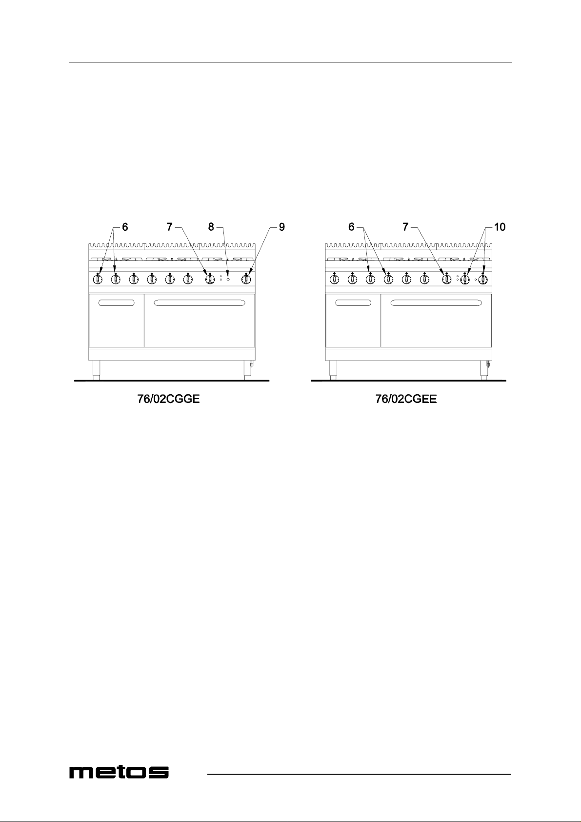
By way of example, below are represented two of the most comprehensive appliances in
this family. Refer to the "Installation and connection drawings" at t he end of this manual
to see a precise graphic representation of your specific appliance.
2.9.2003 Rev. 1.0
Fig. 2
6. Open burner knob
7. Hot cupboard knob
8. Piezoelectric ignition
9. Gas oven knob
10. Electric oven knobs
10
Page 17
Operating instructions
4.2.2 Turning the open burners on and off
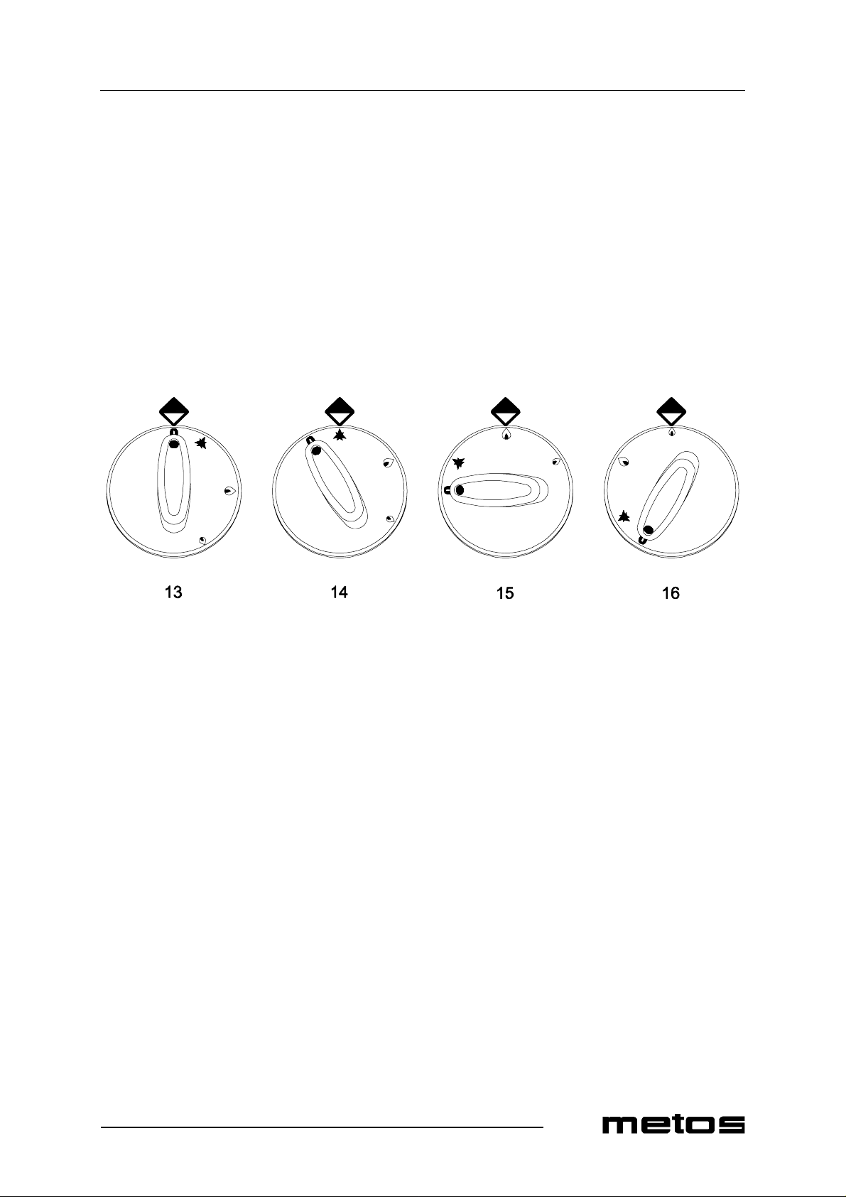
• To light the pilot flame, press the knob and turn it anti-clockwise to the position
shown as item 14 in Fig. 3 ;
• hold down the knob and at the same time place a flame next to the pilot burner;
• after light ing the pil ot flame, hold down t he kn ob for 15 more s econds to al low the
thermocoup le to heat. If the pilot fla me goes out when you rel ease the knob, repeat
the operation;
• burner output c an be control led wi thi n a ra nge be twe en posi tio ns s hown as i te m 15
and item 16 in Fig. 3;
• to turn off the main burner, turn the knob clockwise to the position shown as item
14;
• to turn off the pilot flame as well, turn the knob clockwise to the "OFF" position
(item 13).
2.9.2003 Rev. 1.0
Fig. 3
13. "OFF" posit ion
14. "PILO T FL AM E LI GH TIN G" position
15. "HIGH" position
16. "LOW" position
11
Page 18
Operating instructions
4.2.3 Turning on the gas oven
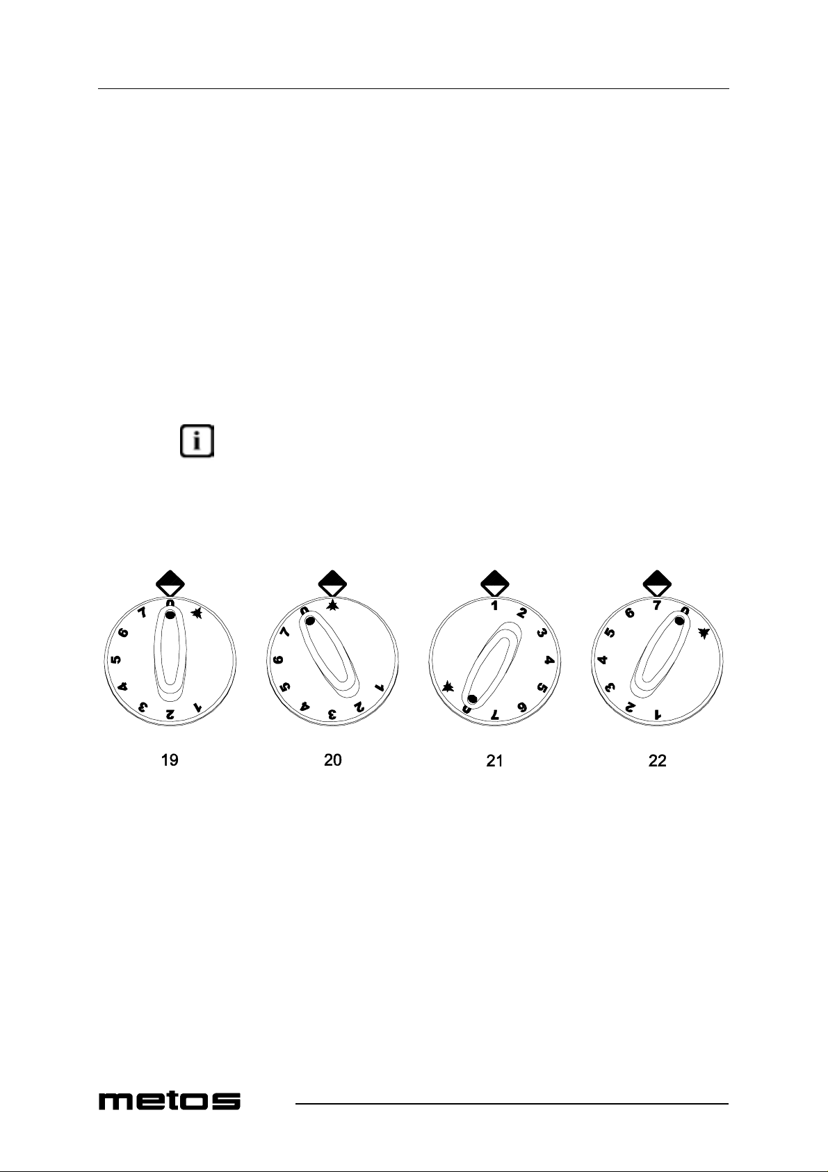
• To light the gas oven pilo t fla me, press and t urn th e knob ant i-cloc kwise to the position sho wn as item 20 in Fig. 4;
• hold down the knob and at the same time push the ignition button (see item 8 in
Fig. 2 further above);
• check pilot flame lighting through the viewing hole located in the bottom plate of
the cooking chamber;
• after lighti ng the pilot flame, hold down the knob for 15 more secon ds in order for
the thermocouple to heat. If the pilot flame goes out when you release the knob,
repeat the operation;
• oven temperature can be controlled within a range between positions shown as
item 21 and item 22 in Fig . 4 (80-300°C/176-572°F and all values in between ) ;
• to turn off the main burner, turn the knob clockwise to the position shown as item
20;
• to turn off the pilot flame as well, turn the knob clockwise to the "OFF" position
(item 19).
An unplea sant s mel l t he ver y f i rst t im e it is op era te d c an be co n sider ed as c omp lete ly nor mal. In fact, this is due to the overheating of insulating materials and residues of oil used
during the metal working process. The first time you turn the oven on, don’t place any
food in the cooki ng c hamber and set the te mpera ture to 300°C (482° F) unt il the s mell dis appears.
2.9.2003 Rev. 1.0
12
Fig. 4
19. "OFF" posit ion
20. "PILO T FL AM E LI GH TIN G" position
21. 80°C (176°F) pos ition (lowest temper ature)
22. 300°C (572°F) position (highest temperature)
Below are the average temperatures at the centre of chamber of the oven corresponding
to each knob position:
1. 80°C (176°F)
2. 110°C (230°F)
3. 140°C (284°F)
4. 180°C (356°F)
5. 220°C (428°F)
6. 260°C (500°F)
Page 19
Operating instructions
7. 300°C (572°F)
4.2.4 Turning on the electric oven
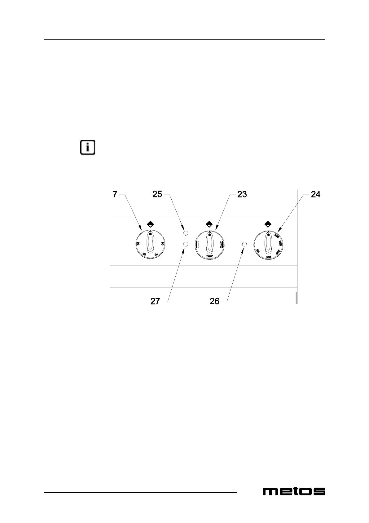
Select the required heating direction using the knob shown as item 23 in Fig. 5. Set the
cooking chamber temperature by turning the operating thermostat knob clockwise (item
24). The heating el ements will s tart o pera ting a nd bo th t he power indi cator li ght (ite m 25)
and the oven operation indic ator light (it em 26) will light up. The operat ion indicat or light
will go ou t as soo n as th e set tempera tu re ha s be en re ached. Ov en te m per ature can be set
from 50°C (122°F) to 300°C (572°F) and to any value in between.
An unplea sant s mel l t he ver y f i rst t im e it is op era te d c an be co n sider ed as c omp lete ly nor mal. In fact, this is due to the overheating of insulating materials and residues of oil used
during the metal working process. The first time you turn it on, don’t place any food in
the cooking chamber and set the temperatur e to 300°C (482°F) unt il the smell disa ppears.
2.9.2003 Rev. 1.0
Fig. 5
7. Hot cupboard therm ostat knob
23. Knob to select oven he ating direction
24. Electric o ven thermostat knob
25. Power indicator light
26. Electric oven operation indicator light
27. Hot cupboard operation indicator light
13
Page 20

Operating instructions
4.2.5 Turning on the hot cupboard
Select the des ired t empera ture u sing t he hot cupb oard knob (it em 7 i n Fig. 5) . T he heati ng
element will start operating and the op eration indicator light (item 27 in Fig. 5) will light
up. This indicator light will go out as soon as the set temperature has been reached. Hot
cupboard temperature can be set from 30°C (86°F) to 90°C (194°F) and to any value in
between.
An unplea sant s mel l t he ver y f i rst t im e it is op era te d c an be co n sider ed as c omp lete ly nor mal. In fact, this is due to the overheating of insulating materials and residues of oil used
during the metal working process. The first time you turn it on, don’t place any food in
the cooking cha mber and set the temperature to 90°C (194°F) until the smell disappears.
4.2.6 Safety thermostat
This appliance is equipped with a safety thermostat. Should the temperature inside the
cooking chamber exceed a limit value, all oven functions will be disabled and only the
power indicator light will remain on (item 25 in Fig. 5 further above). This feature is a
safety precaution which protects the appliance in the event of a failure or use against the
instructions. If the safety thermostat trips, disconnect the appliance from power supply
and call the serv i ce .
2.9.2003 Rev. 1.0
4.2.7 Preheating
Preheating the chambers will ensure excellent cooking results. To do so, make sure that
the door is closed and set cooking chamber temperature to a value that is about 25-50°C
(45-90°F) highe r than the require d c ooking te mperature . Cons ideri ng the de cr ease i n temperature that occurs in the chamber when you open the oven door, you should wait until
the set temperature has stabil ised (the "heat ing on" indi cator light goes out) before pla cing
any products int o the oven a nd settin g the cooking t empera ture. If you need t o cook fo odstuffs that require high temperatures, leave the pans or wire racks in the oven while preheating it.
14
Page 21

Operating instructions
4.3 After-use care
4.3.1 Cleaning
Before cleaning, turn off the appliance, shut off gas supply upstream of it and dis connect
power supply using the safety switch located outside the applianc e.
General information
The main causes f o r stainless steel wear or corros i o n are:
2.9.2003 Rev. 1.0
• using abrasive or acid detergents
drochloric a cid or sodi um hypoch lorite (bleac h). There fore , before buyi ng a dete rgent product, make sure it does not corrode stainless steel (see also paragraph
"Routine cleaning" below);
• stagnation of ferrous deposits
flowing through the piping, especially after the appliance has remained idle for
some time). There fore, avoid s uch stagnat ion; do not use wi re wool pads to re move
the most stubborn food residues. Use, rather, pads or spatulas made of stainless
steel or softer, non-ferrous materials ;
• stagnation of substances having acid components
sauces, sa lt, et c. Th erefore , preve nt prolong ed c ontac t of thes e subst ances wi th th e
stainless steel parts of the appliance. The evaporation of saline solutions over the
surfaces of the appliance is particularly harmful to them.
, especially chlorine-based products such as hy-
(such as those created by rust dissolved in the water
such as vinegar, lemon juice,
Routine cleaning
Cleaning the appli an ce th orough ly eve ry d ay wil l k eep i t in p erfect c onditi on a nd inc reas e
its lifetime. Clean the appliance with a damp cloth using water and soap or detergents,
provided that they are not acid or abrasive as discussed further above. Such detergents
should not even be used to wash the floor near the appliance , as thei r fume s may deposit
on the steel surfaces and damage them. If the appliance is very dirty, use a synthetic
Scotch-Brite™ type sponge. Rinse it off with clean water and wipe it dry with a clean
cloth. Do not rub the appliance with steel wool pads as they could leave rust stains. For
the same reason, avoid touching the appliance with ferrous objects.
Never use direc t water jets to clean the appliance because this cou ld result in water entering into it and damag ing it.
Stains and abrasions on the steel surface
Scratches and dark stains may be smoothed or remove d using stai nless steel wool pads or
synthetic abrasive sponges, which should always be rubbed in the same direction as the
satin finish.
Rust
Should you need to e limin ate rus t st ains , cont act manuf acture rs of in dustri al deterg ents to
find a detergent that can remove such stains. Industrial descaling products can also be
used to that end. After rubbing off the stain and rinsing with clean water, an alkaline detergent may be required to neutralise any acid compounds left on the surface.
15
Page 22

Operating instructions
4.3.2 Idle period
If the appliance wi ll remain idle for a certain period of time, clean it and wipe it dry first,
and then apply a film of a suitab le product (such as vase lin e oil spray or si milar pr oducts)
to protect it. Shut off ga s a nd power supply upstream of the appli ance.
To avoid the appearance of corrosion spots, make sure that any salt residues left on the
inter n al and ex t er n al wa ll s ar e ca r ef u ll y re mo v ed .
4.3.3 Periodic maintenance
Only qualified personnel are allowed to carry out service and maintena nce operations.
The following maintenance operations should be performed at least once a ye ar:
• checking for proper operation of all control and safety devices;
• checking burner com bustion, i.e.:
1. ignition;
2. combustion safety;
3. checking fo r proper oper ation throu ghout th e ent ire HIGH-to -LOW contr ol
2.9.2003 Rev. 1.0
range.
We recommend signing a service agreement providing for at least one check-up a year.
16
Page 23
Installation
5. Installation
5.1 General infor mat ion
The manufacturer cannot be held liable for any damage to property or injury to persons
deriving from installation errors or from inappropriate use of the appliance and is not responsible for any faults caused by defective installation. In such cases, the warra nty shall
be null and void.
The appliance should be installed, serviced, connected to the gas system, to the power
supply and started up only by an authorized installer, who must comply with the safety
regulations in force in the place where the appliance is being installed.
2.9.2003 Rev. 1.0
5.1.1 Regulatory installation conditions
For your information, we remind you that all appliances installed in public assembly
buildings must meet all the requirements listed below. The appliance should be both installed and serviced in accordance with all applicable regulations and standards in force,
namely:
• safety regulations on fire hazard and panic in public assembly buildings.
• general regul ations ap p licable t o all appliances;
• systems burning combustible gas and liquefied hydrocarbons.
Then, follow the specific regulations acc ording to the type of gas being use d.
• heating, ventilation, refrigeration, air conditioning, and generation of steam and
hot water for sanitary use;
• install ation of foodservice cooking appliances;
• specific re gul ations a ppl icabl e to e ach t ype of publ ic assembl y bui lding ( hos pital s,
shops, etc.).
5.2 Exhausting fumes
The appliance should be installed in a well-ventilated a rea, if possible under a vent hood,
in complianc e wit h al l appl ic ab le reg ulati ons in forc e. This wi ll en su re t ha t all burn t g as es
produced during the combustion process are completely exhausted. T he amount of ai r required for combustion is shown in the "Te chnical Specifications Table" at the end of this
manual, under "Air required for combustion".
In compliance with applicable installation regulations in force, our appliances belong to
the type shown under "Construction type" in the "Technic al specifications table".
17
Page 24

Installation
5.3 Possible environmental interference
If the appliance is installed with its sides next to flammable walls (made of wood or s im ilar materials) or to heat-sensitive walls (made of plasterboard or si mi lar materials), sui table protective mea sures should be taken to keep suc h walls undamaged. Therefore, app ly
a coating to insulate the walls from radiative heat or keep a minimum clearance of 100
mm (4") from the side and back panels of the appliance.
If the appliance is installed in the immediate vicinity of other electric appliances, ensure
that they do not interfere with each other. They should all have independent power supplies.
5.4 Preparing for installation
Check that the appliance is pre-set to use the gas family available at the place of use. If
the available g as is different, you will need to convert the appli anc e to use this othe r type
of gas. For directions, please refer to section "Adjustment instructions" below.
Check that th e appliance is pr e- set to opera te on the voltage available at the place of use.
Should the available voltage rating be different, do not install the appliance.
2.9.2003 Rev. 1.0
5.5 Storage
If the appliance has been stored in a warehouse where room temperature is below 0°C
(32°F), it should be warmed up to at least +10°C (50°F) before switching it on.
5.6 Tr ansporting th e applianc e
The best way to transport this appliance is inside its packing to protect it from outside
damage. After the appliance has been unpacked, use wooden spacers if you should need
to lift it up.
5.7 Unpacking the appliance
Prior to installation, remove all packaging m aterials from the appliance. Certain parts are
wrapped up in adhesive fil m, which should be carefully removed. Remove any glue traces
left on the appli ance thoroughly using non -flammable sol vents. It is forbidden to us e abrasive substances.
5.8 Disposing of packaging materials
18
All packaging materials must be disposed of in compliance with applicable local regulations in force where the appliance is being installed. Pa ckaging materials should be separated accordi ng to their types and de livere d to specif ic coll ecti on sites. E nsure comp liance
with environmental protection regulations.
Page 25

2.9.2003 Rev. 1.0
Installation
5.9 Positioning the appliance
Level the appliance using a level. Height can be adjusted with the help of the adjustable
feet.
5.10 Electrical connections (versions with electric oven and/or hot
cupboard)
5.10.1 General information
The appliance should be operated only when properly connected to an effective earthing
(grounding) system.
The appliance is pre-set to be wired to the electrical switchboard. Before connecting the
appliance to the power supply network, check:
• that dis tribution ne twork vol tage matc hes the volt age shown on the appl iance’s ra ting plate;
• that the grounding (earthing) sys tem is effective;
• that the power cord is made of rubber and is of at least the same quality as cable
type H07RN-F, wit h conducto rs having a cross section s uited to t he maximum loa d
they will carry (ref er to "Technic al spe cifi cat ions t able" at the end of t his m anual );
• an effective mul ti -pole bre aker ha ving a c ontac t gap of a t lea st 3 mm sho uld be fi tted upstream of the appliance at the time of installation. The multi-pole breaker
should be i nsta lled i n the im medi ate vi cinit y of t he appl iance a nd be readil y acc essible. We recommend fitting a thermal-magne tic circuit breaker with built-in fuse
protection;
• the power cord of the appliance should not be exposed to direct heat sources.
19
Page 26
2.9.2003 Rev. 1.0
Installation
5.10.2 Connecting a type "Y" power cord to the appliance’s terminal block
The appliance is supp lied c omplete with po wer cord. The powe r cord can only be replaced
by the manufacturer, by the manufacturer’ s service or by a te chnician havi ng similar qua lifications.
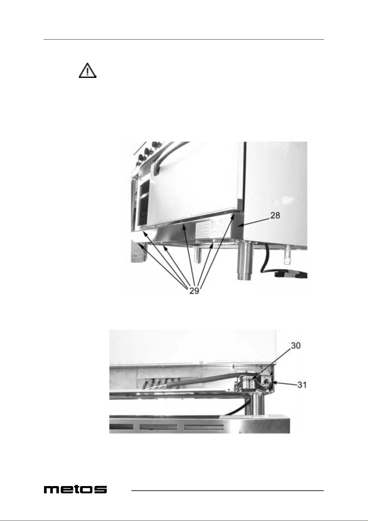
To access the power supply te rminal block, proceed a s fol lows :
• disconnect power;
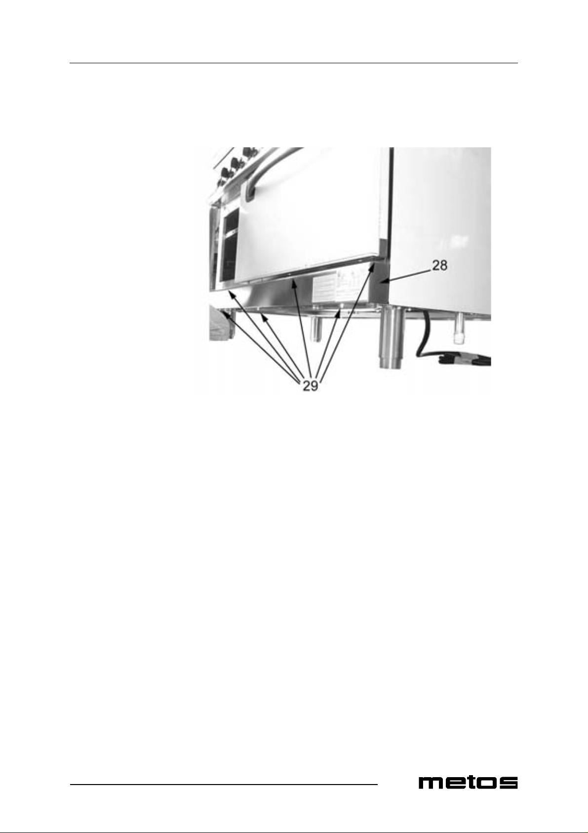
• remove the lower front panel (item 28 in Fig. 6) by unscrewi ng the several sc rews
shown as item 29.
Fig. 6
28. Lower front panel
29. Fixi n g s c rews
Fig. 7
30. Terminal block
31. Cable gland
20
Page 27

Installation
2.9.2003 Rev. 1.0
The power cord should be locked in place with the cable gland (item 31 in Fig. 7) so as to
avoid the risk of tearing it.
The length of the ground (earth) cab le should be such as t o al low it to suffer any possible
mechani cal stress after the li v e leads.
21
Page 28
Installation
5.11 Gas supply connection
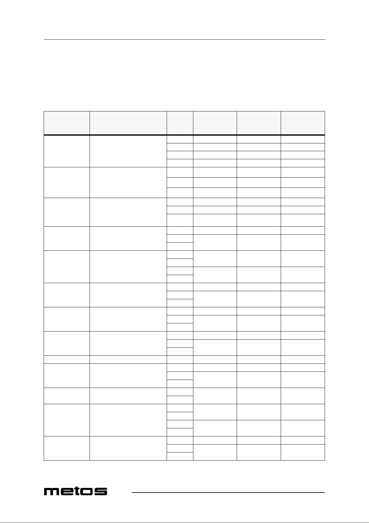
This appliance is designed to burn natural and liquid gas. To find out the category to
which this appliance belongs in the country where it is installed, please refer to the table
below.
Table 1: gas categories and pressure values
2.9.2003 Rev. 1.0
COUNTRY
Belgium
France
Spain
Great Britain
Ireland
Greece
Italy
Italia n S w itzerland
Portugal
Austria
German Switzerland
Germany II2ELL3B/P
Finland II2H3B/P
Denmark II2H3B/P
Sweden II2H3B/P
Luxembourg I2E G20 20 17 25
Netherlands II2L3B/P
Norway I3B/P
Hungary II2HS3B/P
Czech Republic II2H3B/P
APPLIANCE
CATEGORY
II2E+3+
II2H3+
II2H3+
II2H3B/P
GAS
G20201725
G25251730
G30282535
G31372545
G20201725
G30282535
G31372545
G20201725
G30302535
G31372545
G20201725
G30
G31
G20
G25
G30
G31
G20201725
G30
G31
G20201725
G30
G31
G20201725
G30
G31
G25252030
G30
G31
G30
G31
G20
G25.1
G30
G31
G20201725
G30
G31
RATED
PRESSURE
(mbar)
50 42.5 57.5
20 17 25
50 42.5 57.5
30 25 35
30 25 35
30 25 35
30 25 35
30 25 35
25 20 33
30 25 35
30 25 35
MINIMUM
PRESSURE
(mbar)
MAXIMUM
PRESSURE
(mbar)
22
Page 29

Installation
2.9.2003 Rev. 1.0
The appliance sho uld be conne cted to t he gas suppl y by means of metal pipes --eithe r rigid
or flexible-- having an adequate di am eter (see "Technical speci fications table" at the end
of this manual). When joining pipe fittings, never use oakum or Teflon as their residues
could get to the valve and je opardise its operation. Instead, inter pose a seal gaske t suitable
for use in gas systems. Do not forge t to fit a s hutoff val ve on the ga s supply lin e upstr eam
of the appliance, which should be closed whene ver the appliance is not in operation. Operating pressure values are shown on the rating plate and in "Table 1: gas categories and
pressure values" above.
After connecting the appliance to the gas system, check for leaks at joints and pipe fittings; to do so, use soap y water or a specific leak detec tor (spray).
23
Page 30
2.9.2003 Rev. 1.0
Installation
5.12 Checking gas supply pressure after installation
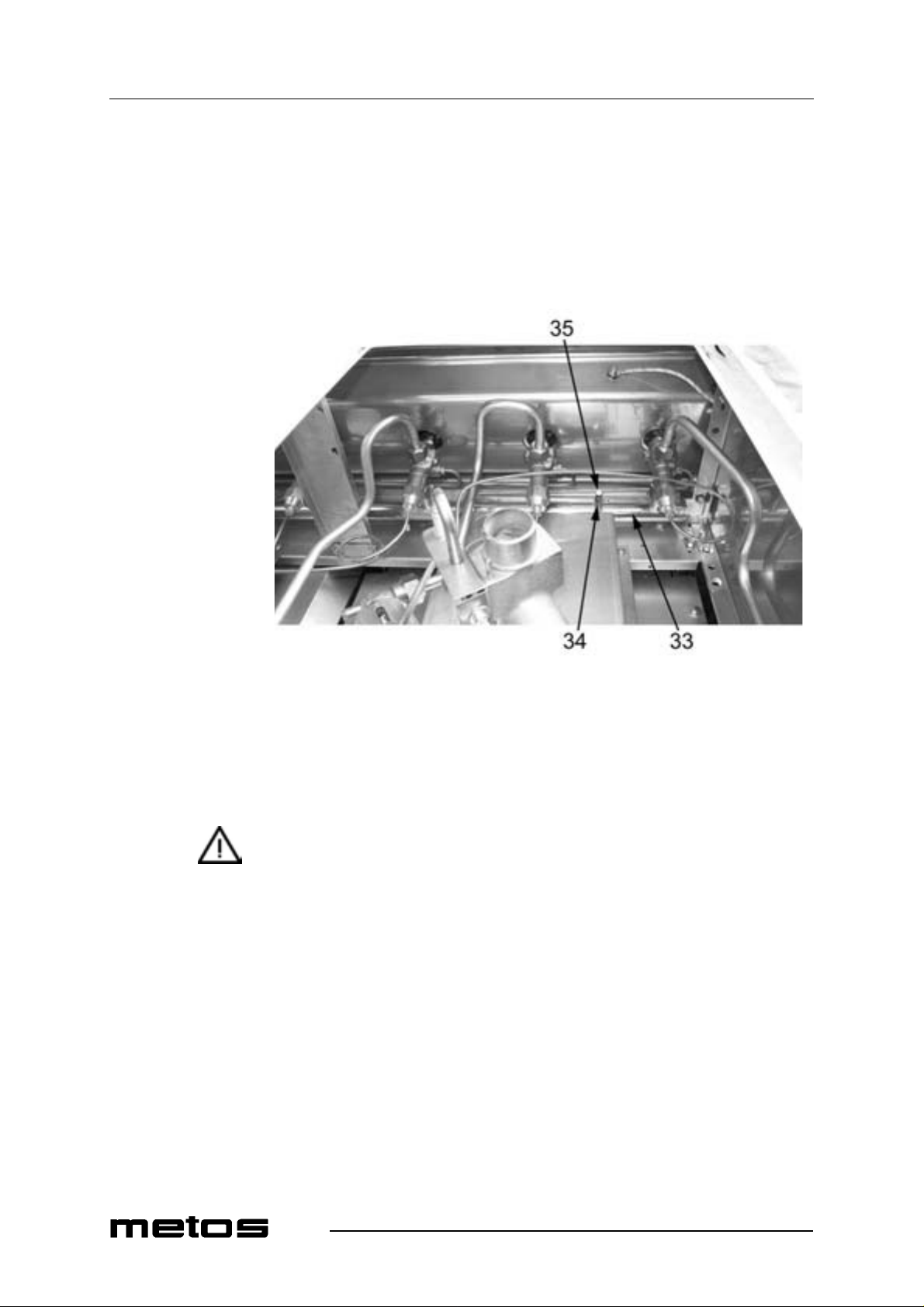
Gas supply pressure can be measured with a liquid-filled pressure gauge (for example, a
U-shaped pressure gauge, minimum scale division 0.1 mbar) or a digital gauge. Proceed
as follows:
• remove the left gra te, burners, and drip pan;
• unscrew the screw (item 35 in Fig. 8) on the pressure port (item 34);
Fig. 8
33. Gas ra mp
34. Pressure port
35. Pressure port sealing s cre w
• place the pressu re gauge;
• start up the appliance by following the instructions in the user’s manual;
• check supply press ure;
• if th e measur ed pressure val u e is within the range shown in "Table 1: gas catego-
ries and pressure values", the appliance can be started up. Otherwise, contact the
gas utility company.
• remove the pressure gauge;
• replace the sealing screw (item 35);
• check f o r le ak s (see p r ev i ou s ch apter "Checking gas supply pressure after instal-
lation").
24
Page 31
2.9.2003 Rev. 1.0
Installation
5.13 Gas technical specifications
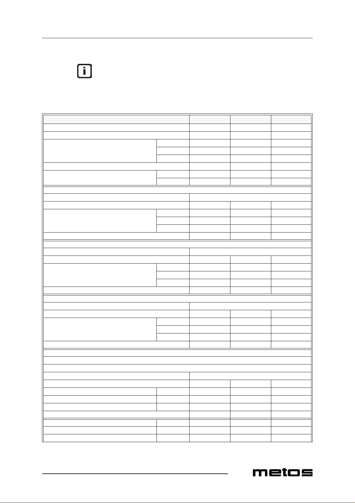
The appliance should be started up at its rated output with the nozzles shown in "Table 2:
burner specifications" below. All the necessary nozzles are provided in a small bag to-
gether with the appliance. The nozzles of the main burners are marked in hundredths of
mm, while those of pilot flame s have a reference number.
Table 2: burner specifications
C D Oven
Rated output (kW) 3.5 5.6 7.9
Minimum output (kW) 0.9 1.8 /
G20 0.370 0.593 0.836
Natural gas consumpt ion (m³/h)
Liquid gas consumption (kg/h) 0.274 0.438 0.618
Town gas consumption (m³ /h)
G20 20mbar
Rated pr essure (mba r) 20
Reduced pr essure (mbar), minimum 1 1.8
Nozzles (1/100 mm)
Primary air distance (mm) 0 3 0
G25 20mbar
Rated pr essure (mba r) 20
Reduced pr essure (mbar), minimum 1 1.8
Nozzles (1/100 mm)
Primary air distance (mm) 0 3 15*
G25 25mbar
Rated pr essure (mba r) 25
Reduced pr essure (mbar), minimum 1.5 2.5
Nozzles (1/100 mm)
Primary air distance (mm) 0 3 15*
G30/31 28/ 37 m bar
G30/31 30 mbar
G30/31 30/3 7 mb ar
Rated pr essure (mbar) 28 / 30 / 37
Reduced pr essure (mbar), minimum
Nozzles (1/100 mm) Max. 90 115 145
Primar y air distance (m m) 2.5 6 22
G25 0. 431 0.690 0.973
G25.1 0.431 0.690 0.973
G110
G120
Pilot flame 35 35 27·2
Max. 140 170 210
Min.
Pilot flame 35 35 27·2
Max. 150 185 240
Min.
Pilot flame 35 35 27·2
Max. 140 170 220
Min.
Pilot flame 20 20 27·2
Min. 45 65 /
25
Page 32

2.9.2003 Rev. 1.0
Installation
Table 2: burner specifications
C D Oven
G30/31 50 mbar
Rated pr essure (mba r) 50
Reduced pr essure (mbar), minimum
Pilot flame 20 20 16·2
Nozzles (1/100 mm)
Primar y air distance (m m) 2.5 6 12
* Apply th e air regi ster plat e (see chapte r "Repl acing oven burne r nozzles" in sec tion "Ad-
justment instru ctions"). The primary air sleeve should be fitted and adjusted as shown in
this table.
Max. 80 105 125
Min. 45 65 /
26
Page 33
Installation
5.14 Checking operation
1. Start u p the a pplia nce b y following t he ins tructi ons g iven in chapt er "Usi ng the appliance";
2. check for gas leaks;
3. check for flame stability throughout the whole control range by going from high
to low.
5.15 Staff training
Inform all personne l assi gned to oper ate th e appli ance o n how t o use it by r efe rring to t his
user’s manual and hand them out the manual.
5.16 Rating plate
The rating plate showing the specifications of the corresponding model is applied in the
position shown i n the install ation and con nection dra wings and include s the data listed below:
2.9.2003 Rev. 1.0
Manufacturer:
Model: (see front page)
Serial number:
Year of manuf acture:
Category: (see "Technical specifications table")
Heating power: (see "Technical specifications table")
Natura l ga s co nsumption: (see "Technical specifications table")
Liquid gas consumption: (see "Technical specifications table")
Supply pre ssure:
natural gases: G 2 0 (see "Tabl e of categories and gas pressure values" fu r-
ther abo ve)
liquid gases (butane/propane): G30/G31 (see "Ta ble of cate gories and gas pressure values" fur-
ther abo ve)
town gas: G110/G120 (see "Table of categories and gas pressure valu es" fur-
ther abo ve)
Gas inlet pipe size: (see "Technical specifications table")
Supply voltage: (see the label on the pack aging and on the unit)
Applianc e pre-set to use:
27
Page 34

Installation
2.9.2003 Rev. 1.0
28
Page 35

Adjustment instructions
6. Adjustment instructions
To convert (for example) from natural gas to liquid gas, you need to change the nozzles
of main and pilot burners. The appropriate nozzles are shown in "Table 2: burner speci-
fications".
2.9.2003 Rev. 1.0
29
Page 36
Adjustment instructions
6.1 Replacing open burner nozzles
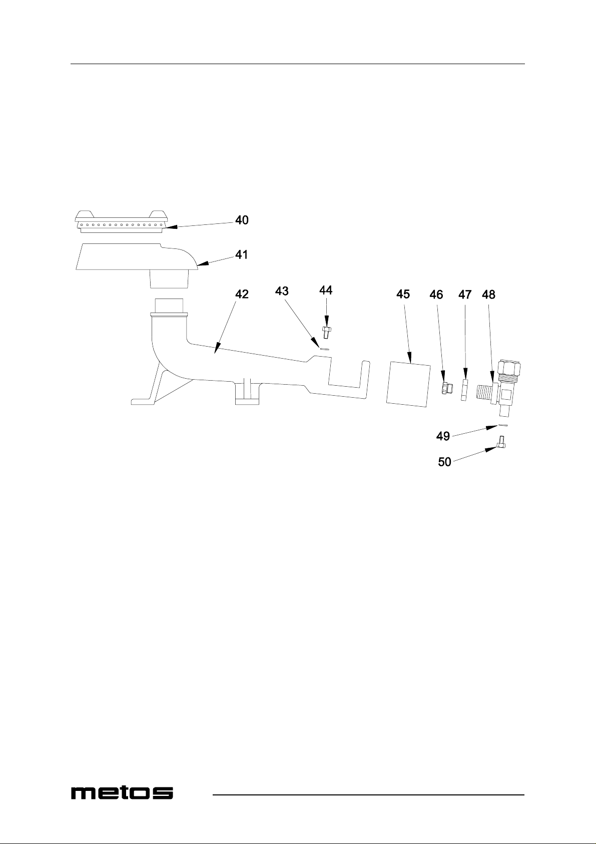
• Remove the gr ate, the fl ame sp reader (item 40 in Fig. 10), t he burne r (i tem 41) a nd
the drip pan;
• unscrew the s crew (it em 44) t hat fi xes th e primary a ir sleeve ( item 45) and re move
the slee ve ;
• unscrew the noz zle (ite m 46) using a 13- mm spanner and fi t a suit able nozzle (refer
to "Table 2: burner specificati ons").
2.9.2003 Rev. 1.0
Fig. 10
40. Flame spreader
41. Burner
42. Venturi tube
43. Washer
44. Air sleeve fixing screw
45. Air sle eve
46. Nozzle
47. Nut
48. Nozzle holder
49. Washer
50. Screw
30
Page 37
Adjustment instructions
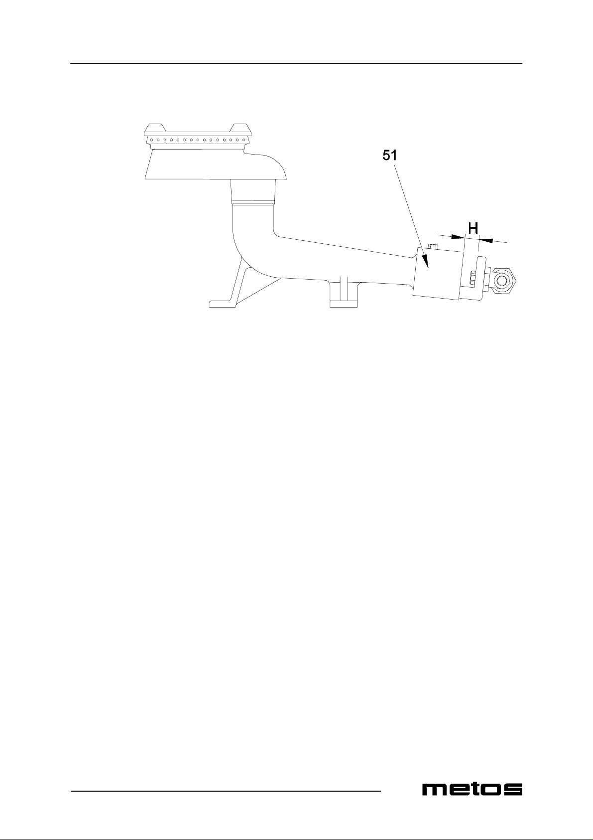
• adjust pri ma ry air distance (H in Fig. 11) according to t he values shown in "Table
Fig. 11
2.9.2003 Rev. 1.0
2: bur ner spe cific at ions".
51. Air sle eve
31
Page 38
2.9.2003 Rev. 1.0
Adjustment instructions
6.2 Replacing the nozzle of open burner pilot flames
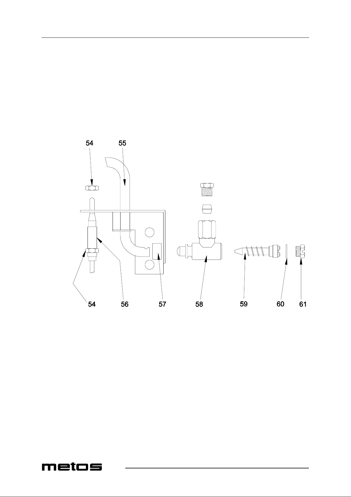
• Unscrew the sealing screw (item 61 in Fig. 12) using an 11-mm spanner, and remove it ;
• unscrew the nozzle (item 59) with a flat-blade screwdriver and remove it;
• fit a s uitabl e n ozz le and s c rew i t do wn compl ete ly (see "T able 2: b urner spe cific a-
tions");
• adjust primary air to the pilot flame by moving the ring shown as item 57;
• the pilot flame should be blue and it should fully wrap up the thermocouple; otherwise, check that you have fitted the right noz zles.
32
Fig. 12
54. Thermocouple fixing nut
55. Pilot flame top
56. Thermocouple
57. Air register ring
58. Pilot flame body
59. Nozzle
60. Gasket
61. Sealing screw
Page 39
Adjustment instructions
6.3 Replacing oven burner nozzles
• Remove the lower front panel (item 28 in Fig. 13) by unscrewing the several
screws shown as item 29;
2.9.2003 Rev. 1.0
Fig. 13
28. Lower front panel
29. Fixi n g s c rews
• open the oven door and take out the bottom plates;
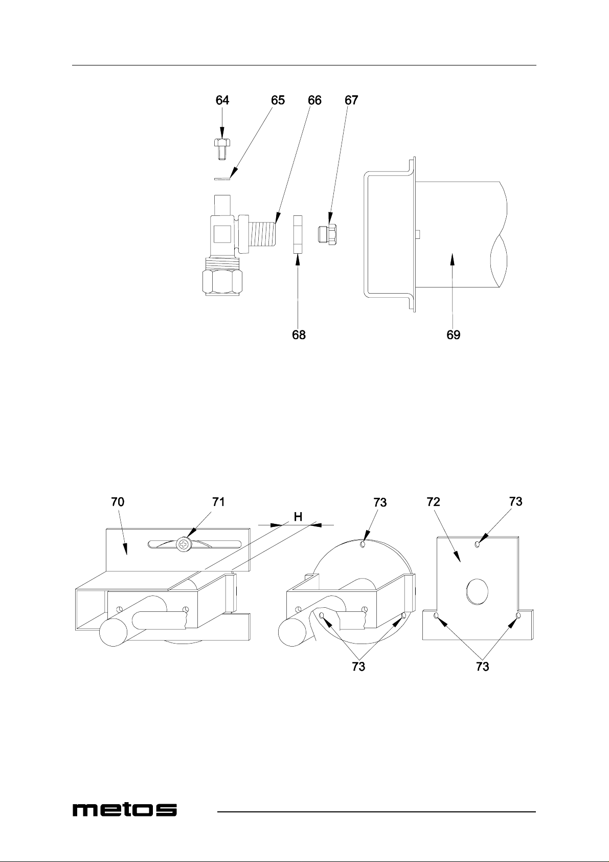
• unscrew the screw (item 71 in Fig. 15) fixin g the primary ai r sleeve (ite m 70 in Fig.
15) and remove it;
• unscrew the nozzle (item 67 in Fig. 14) using a 13-mm spanner, and fit a suitable
nozzle (see "Table 2: burner specifications");
33
Page 40
Adjustment instructions
2.9.2003 Rev. 1.0
Fig. 14
64. Screw
65. Washer
66. Nozzle holder
67. Nozzle
68. Nut
69. Burner
• adjust pri ma ry air distance (H in Fig. 15) according to t he values shown in "Table
2: bur ner spe cific at ions";
34
Fig. 15
70. Primary air sleeve
71. Fixi n g s c rew
72. Fixed air register for G25 natural gases
73. Air register fixing holes
Page 41
Adjustment instructions
• if the applia nce will be usin g type G25 natural gas --a nd only in this cas e--, remove
the air sleeve and fit the air register plate (item 72 in Fig. 15);
• replace the primary air sleeve and adjust it according to the values shown in "Table
2: bur ner spe cific at ions".
6.4 Replacing the nozzle of the oven pilot flame
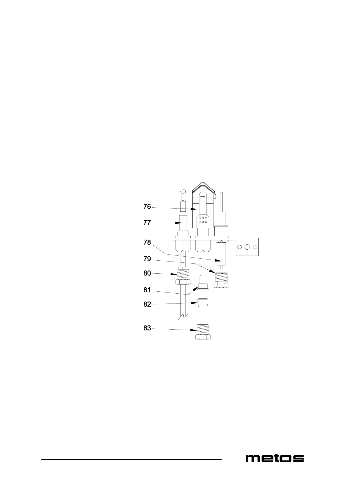
• Place a 12-mm s panner o n the pi lot burner bo dy (i tem 76 in Fi g. 16) to cou nterba lance torsional stress;
• with a 10-mm spanner, unscrew the nut (item 80 in Fig. 16) fixing the thermocouple and remove the thermocouple;
• unscrew the nut fixing the gas pipe (item 83) and remove the pipe;
• take the nozzle (item 81) out of the pilot burner body and replace it with a suitable
one (s ee "Table 2: burner specifications");
• refitting the spare part is a reversal of removal;
• it is not necessary to adjust primary air;
2.9.2003 Rev. 1.0
Fig. 16
76. Pilot flame body
77. Thermocouple
78. Spark plug
79. Spar k pl ug fixing nut
80. Thermocouple fixing nut
81. Nozzle
82. Biconic fitting
83. Gas pipe fixing nut
35
Page 42
Adjustment instructions
6.5 Adjusting minimum output
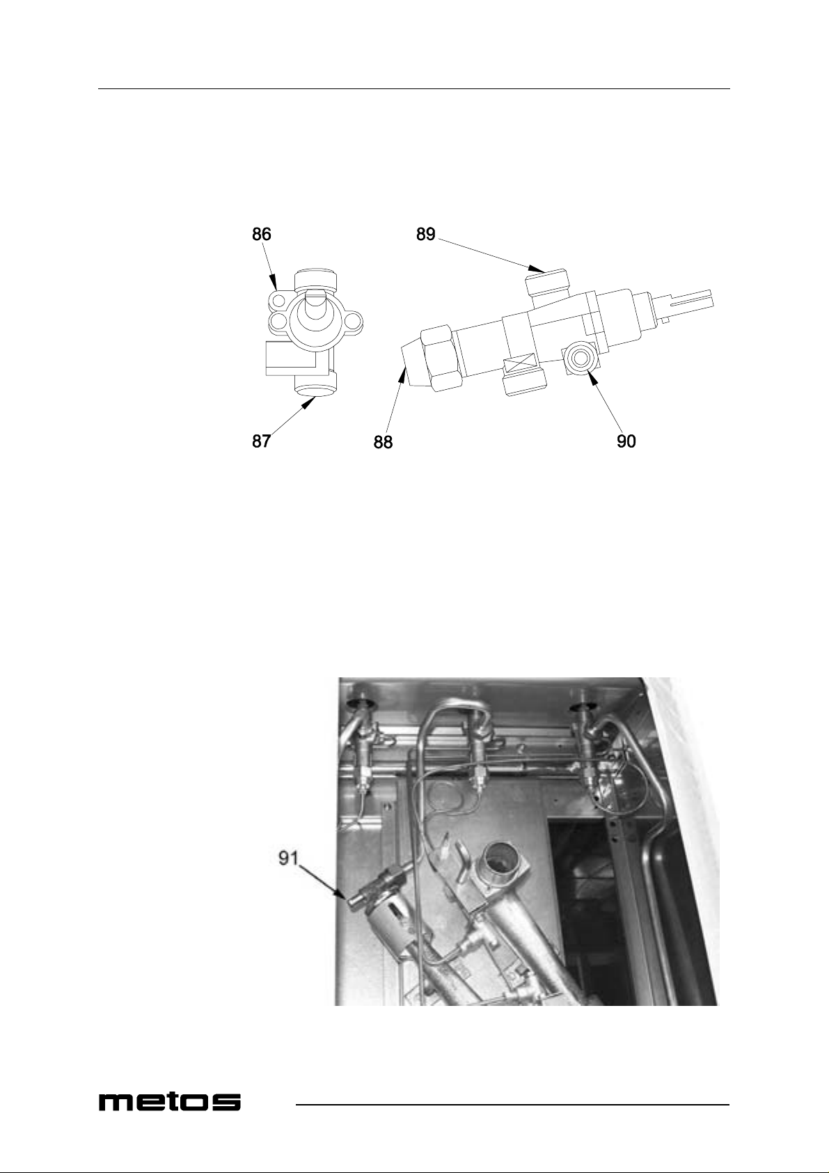
If the applia nce wil l be usi ng l iquid ga ses, remove the k nobs, inse rt a s crewdri ver thro ugh
the hole and completely screw down the screw shown as item 86 in Fig. 17.
2.9.2003 Rev. 1.0
Fig. 17
86. Screw to adjust minimum output
87. Gas inlet pipe fitting
88. Thermocouple pipe fitting
89. Gas outlet pipe fitting
90. Pilot burner pipe fitting
For other types of ga s, you will need to adj ust th e screw as re quired unt il you obt ain a sta ble and even flame. Proceed as follows:
• unscrew the screw shown as item 91 in Fig. 18;
36
Fig. 18
91. Screw
Page 43

Adjustment instructions
• connect a liquid-filled pressure gauge (for example, a U-shaped pressure gauge,
• start up the appliance by following the instructions in the user’s manual;
Gas pressure at mini mum burner output shoul d match the pressure value s shown in "Table
2: burner specifications" under “Reduced pressure (mbar), minimum”.
6.6 Functional check
• Start the appli anc e by following the "Operating instructi ons" ;
• check for leaks;
• check for flame stability throughout the ON- O FF-ON control range;
• check the lighting process along t h e main burner and check that flames are even;
• check for proper operation of pilot flame;
• check that flue ga se s com e out of the corresponding pipes regularly;
• check that there is a good inflow of fresh air.
2.9.2003 Rev. 1.0
minimum scale division 0.1 mbar) or a digital gauge;
37
Page 44

Adjustment instructions
2.9.2003 Rev. 1.0
38
Page 45
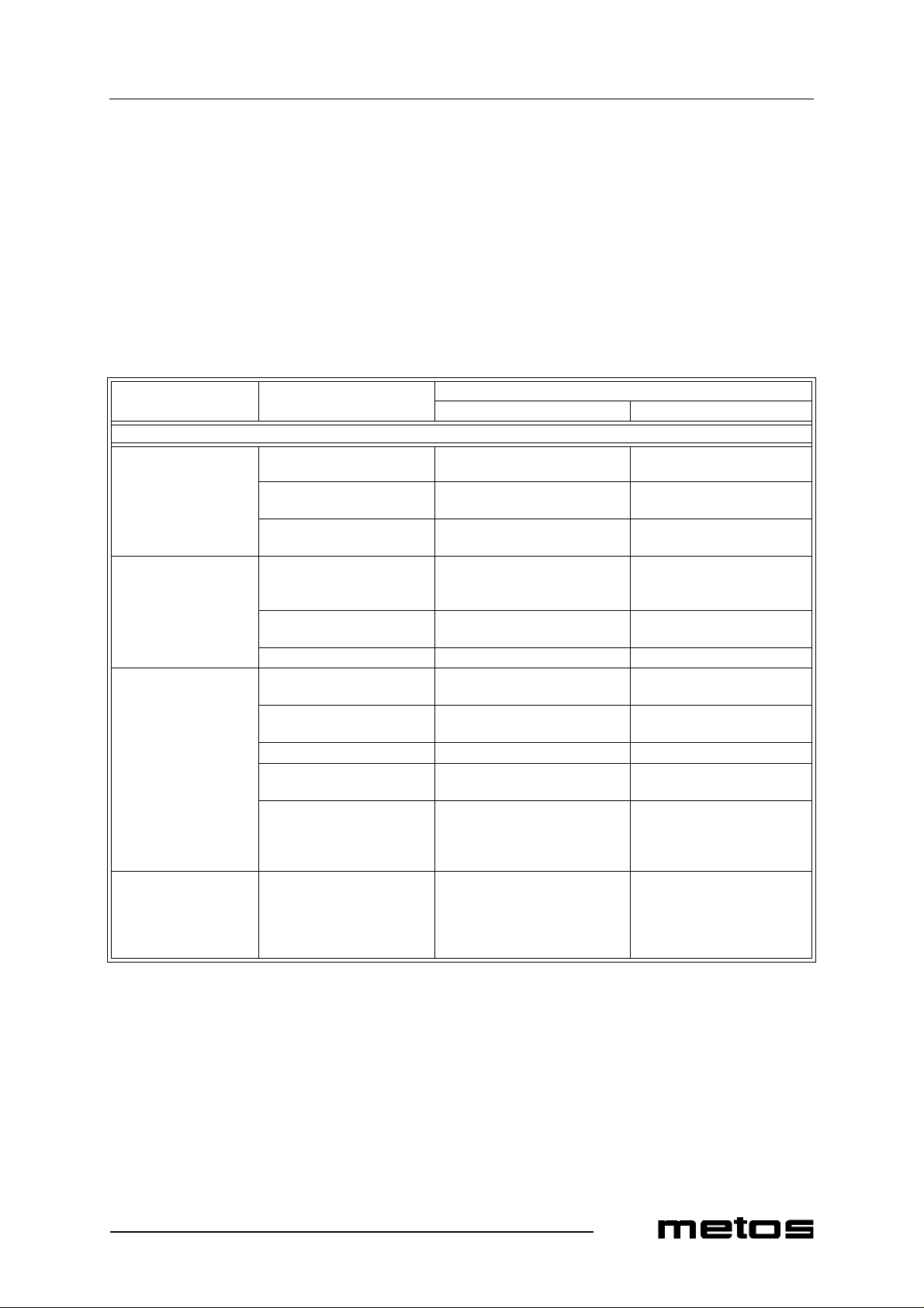
Troubleshooting
7. Troubleshooting
Users are not allowed to perform any maintenance operations on any parts of this appliance. Maintenanc e s hould be carried out by an auth orized technician.
TROUBLE POSSIBLE CAUSES WHAT TO DO
FOR THE USER FOR THE INSTALLER
OPEN BU RNERS
Pilot bur ne r wo n’ t
light:
pressure drop in gas suppl y
pipe
nozzle clogg ed; remove any d ir t fr om th e no z-
gas valve dam aged; replace it;
2.9.2003 Rev. 1.0
contact the gas utility company;
zle;
After releasing the
knob, the pilot burner
goes ou t:
Pilot flame stays lit, but
burner won ’ t lig h t:
When turning the open
burne r ig nition kn ob
from hig h to low , the
burne r go es out:
gas valve k nob not pressed
down firm ly or l ong e nou gh
to heat the thermocouple.
thermocouple faul ty; replace i t;
gas valve dam aged; replace it;
pressure drop in gas suppl y
pipe
nozzle clogg ed; remove any d ir t fr om th e no z-
gas valve dam aged; replace it;
the gas outlet holes on the
burner crow n are clogged;
burner co mponents are not
properly placed one on top
of the ot her;
minimum output too low; adjust minim um output (see
repeat the lightin g procedure;
contact the gas utility company;
zle;
clean the crown;
place them properly;
chapter "Adj usti ng minimum
output" in "Adjustment instructions" section).
39
Page 46
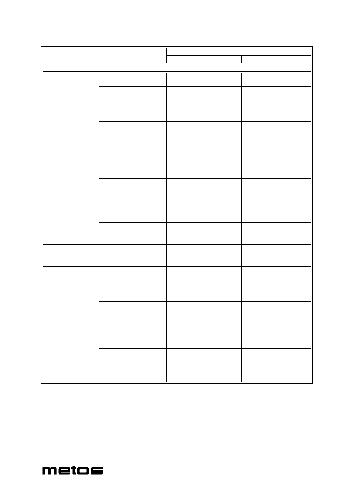
Troubleshooting
TROUBLE POSSIBLE CAUSES WHAT TO DO
FOR THE USER FOR THE INSTALLER
GAS OVEN
Pilot flame won’t ligh t: piezoelectric ignition device
faulty;
the spark plug is not secure-
ly fixed, or the wire connection is wrong;
spark plug insulator damaged;
pressure drop in gas supply
pipe;
nozzle clogg ed; remove any d ir t fr om th e no z-
gas valve/tap damaged; replace it;
After releasing the
knob, the pilot flame
goes ou t:
Pilot flame stays lit, but
burner won’t light:
Temperature control
fails to work:
gas valve knob not pressed
down firmly or long enough
to heat the thermocouple.
thermocouple faul ty; replace i t;
gas valve/tap damaged; replace it;
pressure drop in gas supply
pipe
nozzle clogg ed; remove any d ir t fr om th e no z-
gas valve/tap damaged; replace it;
gas outlet holes on the burn-
er clogged;
thermost at bulb damaged; replace the valve;
thermostat damaged; replace the valve;
repeat the lightin g procedure;
clean the burner;
2.9.2003 Rev. 1.0
replace i t;
check the connection;
replace i t;
contact the gas utility company;
zle;
contact the gas utility company;
zle;
Uneven cooking
(strong difference in
food colour):
temperature is too high; use a lower temperature;
baking pan too close to heat
source;
product divided into pieces
that have different sizes or
thicknesses;
wire shelves not horizontal; level the appliance and check
place the baking pan on the top
slide;
to ensure cooking evenness,
spread fo od over the entire baking pan evenly. In the case of
solid foodstuffs, all the pieces
should have --as much as possible-- the same size, number of
layers or thickness.
that the wire shelves are horizontal using the adjustable feet:
such operation is essential to
ensure even cooking.
40
Page 47
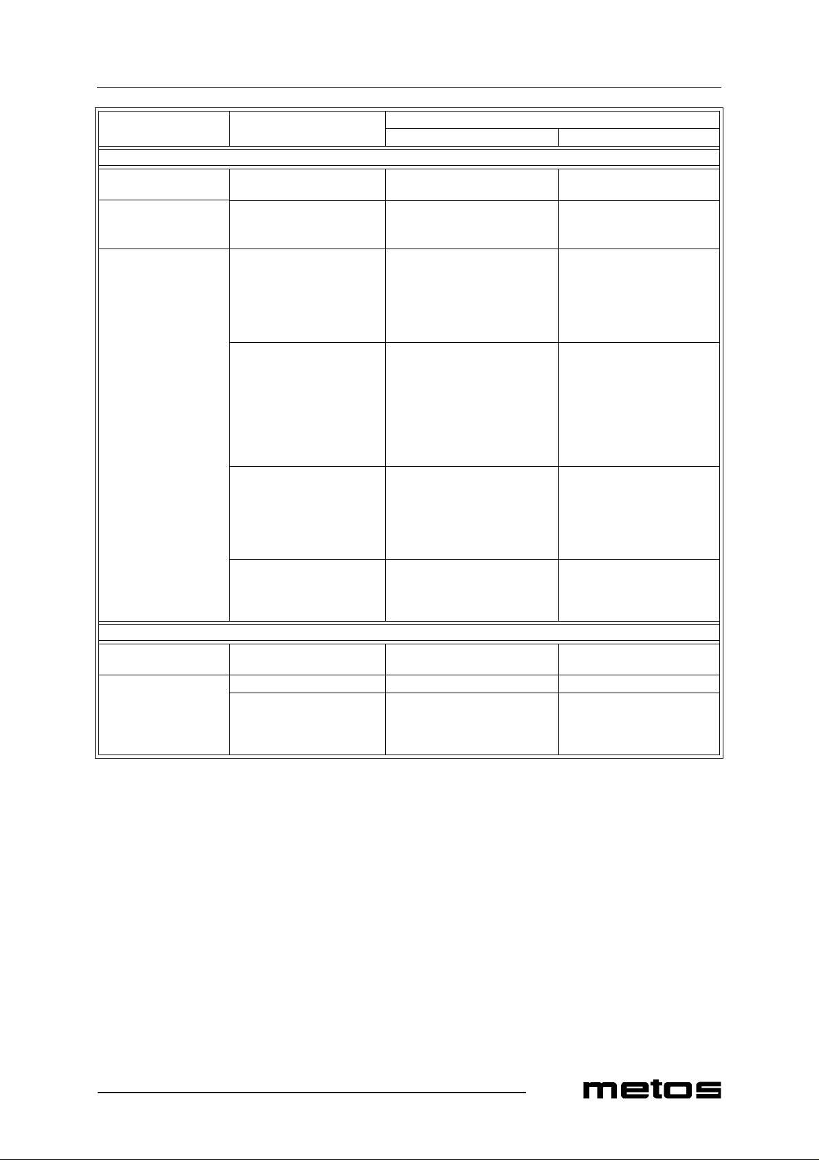
Troubleshooting
TROUBLE POSSIBLE CAUSES WHAT TO DO
FOR THE USER FOR THE INSTALLER
ELECTRIC OVEN
No heating: no power; check that the appliance is be-
ing po w e re d;
A temper at ure i s s et but
the ove n w o n’ t tu rn on :
safety thermostat has
tripped;
2.9.2003 Rev. 1.0
rese t th e th er m o stat
Uneven cooking
(strong difference in
food colour):
selector switch position is
wrong or unsuitable for the
desired cooking method
product divided into pieces
that have different sizes or
thicknesses;
wire shelves not horizontal; level the appliance and check
one of the two heating elements is faulty.
choose a suitable selector
switch position to produce heat
from the oven t op an d b ottom as
required according to the cooking method you intend to use;
to ensure cooking evenness,
spread fo od over the entire baking pan evenly. In the case of
solid foodstuffs, all the pieces
should have --as much as possible-- the same size, number of
layers or thickness.
that the wire shelves are horizontal using the adjustable feet:
such operation is essential to
ensure even cooking.
HOT CUPBOARD
No heating: no power; check that the appliance is be-
ing po w e re d;
A temper at ure i s s et but
the hot cupboard won’t
turn on:
thermostat faulty; replace it;
heating element open; replace it (see chapter "Re-
replace it (refer to the chapters on how to re pl ace heati ng
elements).
placing the hot cupboard
heating element" in section
"Service").
41
Page 48

Troubleshooting
2.9.2003 Rev. 1.0
42
Page 49

Technical specifications
Connection diagrams ...................................................70
Installa tion and conne ction drawin g s..... ................ ....74
Technical specifications table......................................87
CE conformity declaration..........................................89
2.9.2003 Rev. 1.0
9. Technical speci fications
69
Page 50

Page 51
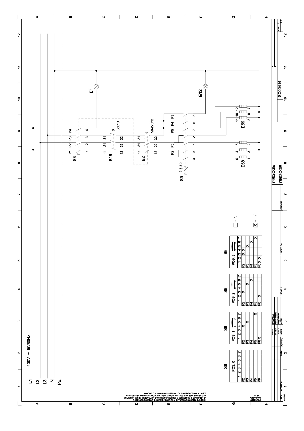
SC00414: wiring di agram 74/02CGE, 76/02CGE - 3/N/PE ~400V 50-60 Hz
Page 52
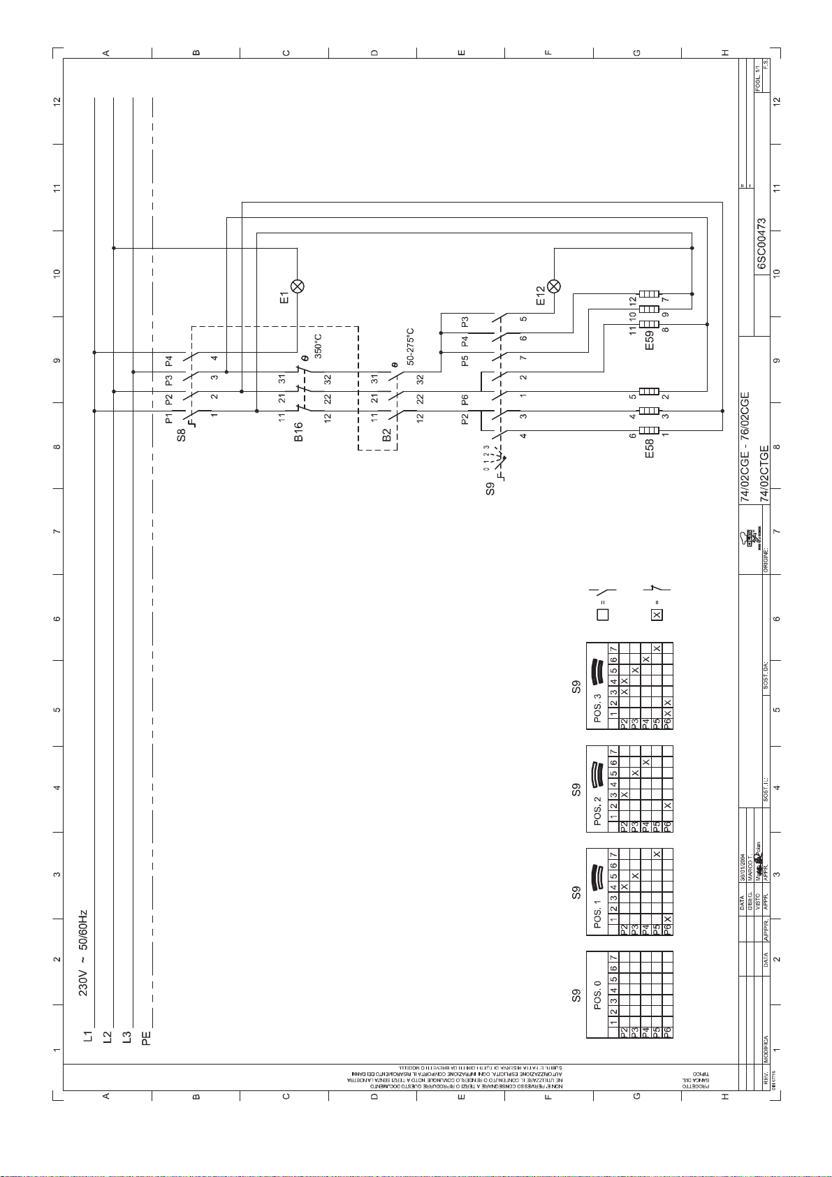
6SC00473: wiring diagram 74/02CGE, 76/02CGE, 74/02CTGE - 3/PE ~230V 50-60 Hz
Page 53
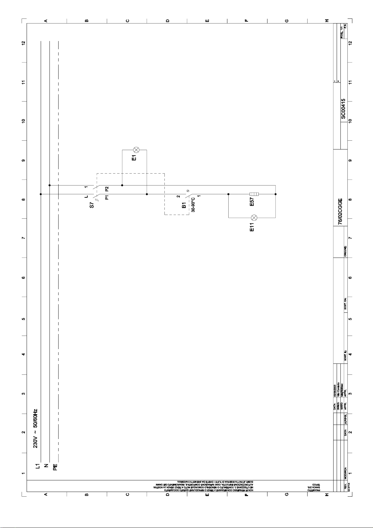
SC00415: wiring diagram 76/02CGGE - 1/N/PE ~230V 50-60Hz
Page 54
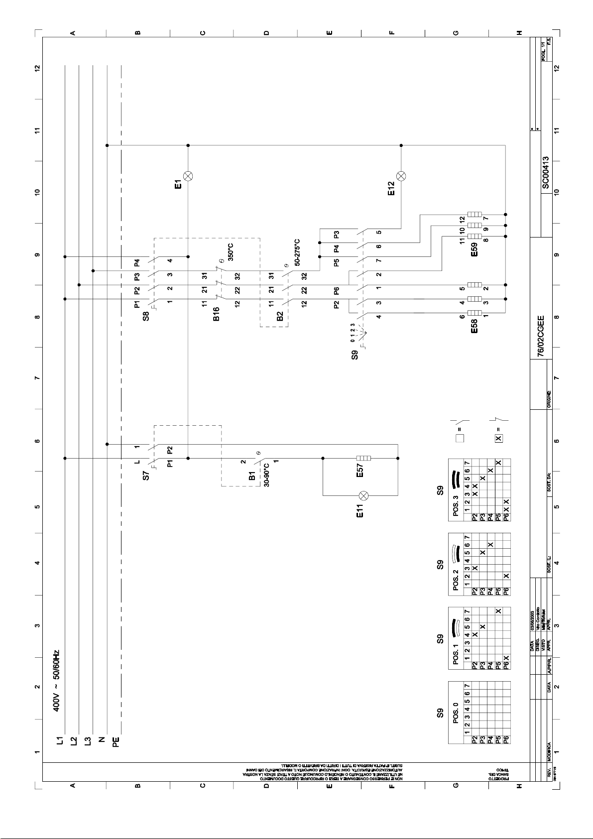
SC00413: wiring di agra m 76/ 02CGEE - 3/N/PE ~400V 50-60Hz
Page 55
Technical specifications
2.9.2003 Rev. 1.0
LE00385: key to wiring diagrams SC00414, 6SC00473
74/02CGE, 76/02CGE -.3/N/PE ~400V 50-60Hz, 3/PE ~230V 50-60Hz
Letter code Art. no. Descriptions Specifications
B2 A044601 Control thermostat 50 - 275°C - 3F
B16 A046150 Safety thermost at 350°C - 3F
E1 A038506 Line pilot lamp 400V - 150°C
E12 A038506 Operation pi lot lamp 400V - 150°C
E58-59 A0 37550 Heating element 2750W - 230V
S8 A046001 Switch 3F
S9 A046750 Switch 4-position
LE00386: key to wiring diagram SC00415
76/02CGGE - 1/N/PE ~230V 50-60Hz
Letter code Art. no. Descriptions Specifications
B1 A046050 Control thermostat 30 - 90°C - 1F
E1 A038506 Line pilot lamp 400V - 150°C
E11 A038506 Operation pi lot lamp 400V - 150°C
E57 A036800 Heating element 420W - 230V
S7 A046000 Switch 1F
LE00384: key to wiring diagram SC00413
76/02CGEE - 3/N/PE ~400V 50-60Hz
Letter code Art. no. Descriptions Specifications
B1 A046050 Control thermostat 30 - 90°C - 1F
B2 A044601 Control thermostat 50 - 275°C - 3F
B16 A046150 Safety thermost at 350°C - 3F
E1 A038506 Line pilot lamp 400V - 150°C
E11 A038506 Operation pi lot lamp 400V - 150°C
E12 A038506 Operation pi lot lamp 400V - 150°C
E57 A036800 Heating element 420W - 230V
E58-59 A0 37550 Heating element 2750W - 230V
S7 A046000 Switch 1F
S8 A046001 Switch 3F
S9 A046750 Change-over switch 4-position
73
Page 56
Technical specifications
2.9.2003 Rev. 1.0
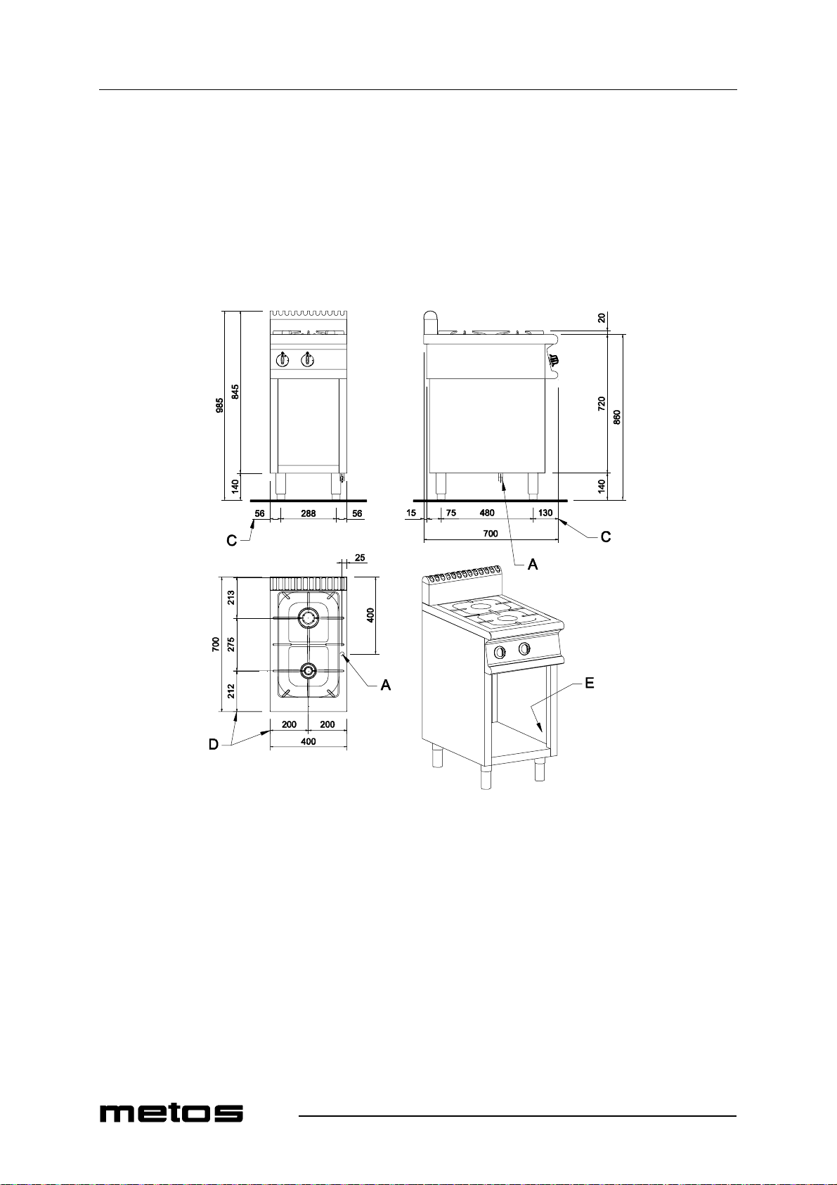
Installation and connection drawing 72/02CG
74
Page 57
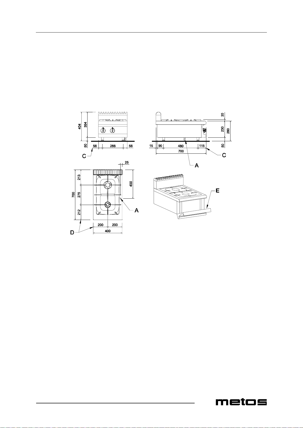
Technical specifications
2.9.2003 Rev. 1.0
Installation and connection drawing 72/02TCG
75
Page 58
Technical specifications
2.9.2003 Rev. 1.0
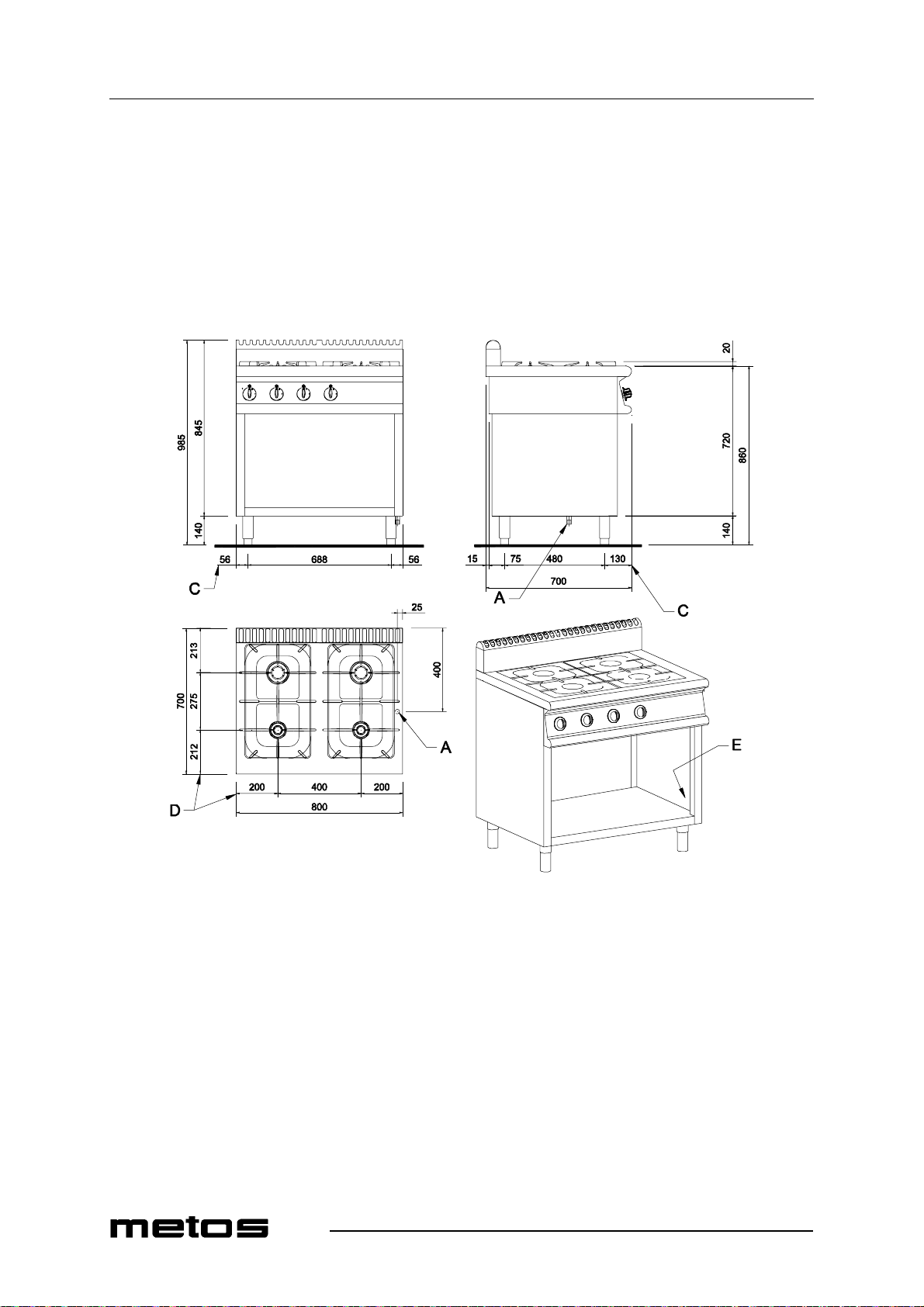
Installation a nd connection drawing 74/02CG
76
Page 59
Technical specifications
2.9.2003 Rev. 1.0
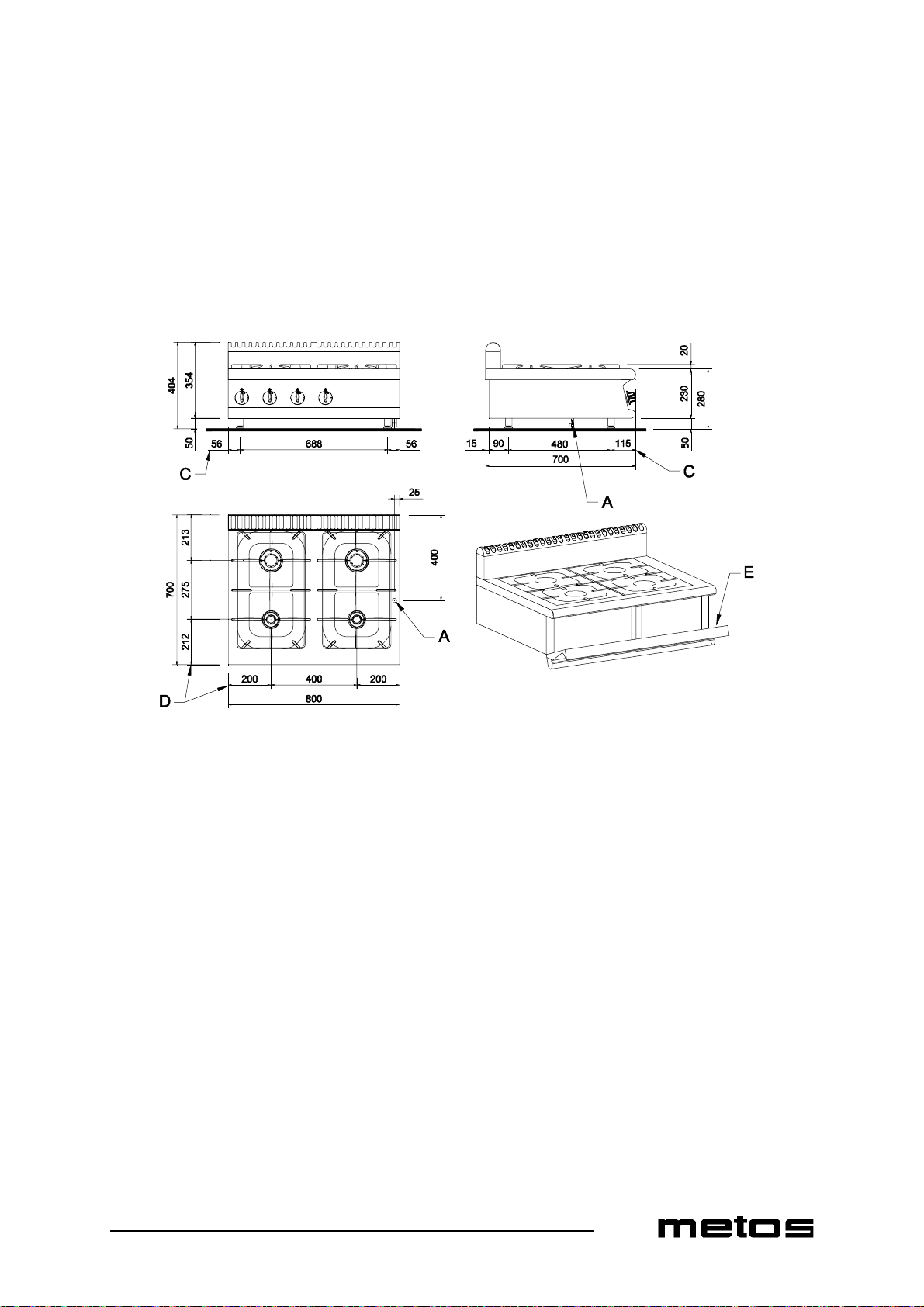
Installation and connection drawing 74/02TCG
77
Page 60
Technical specifications
2.9.2003 Rev. 1.0
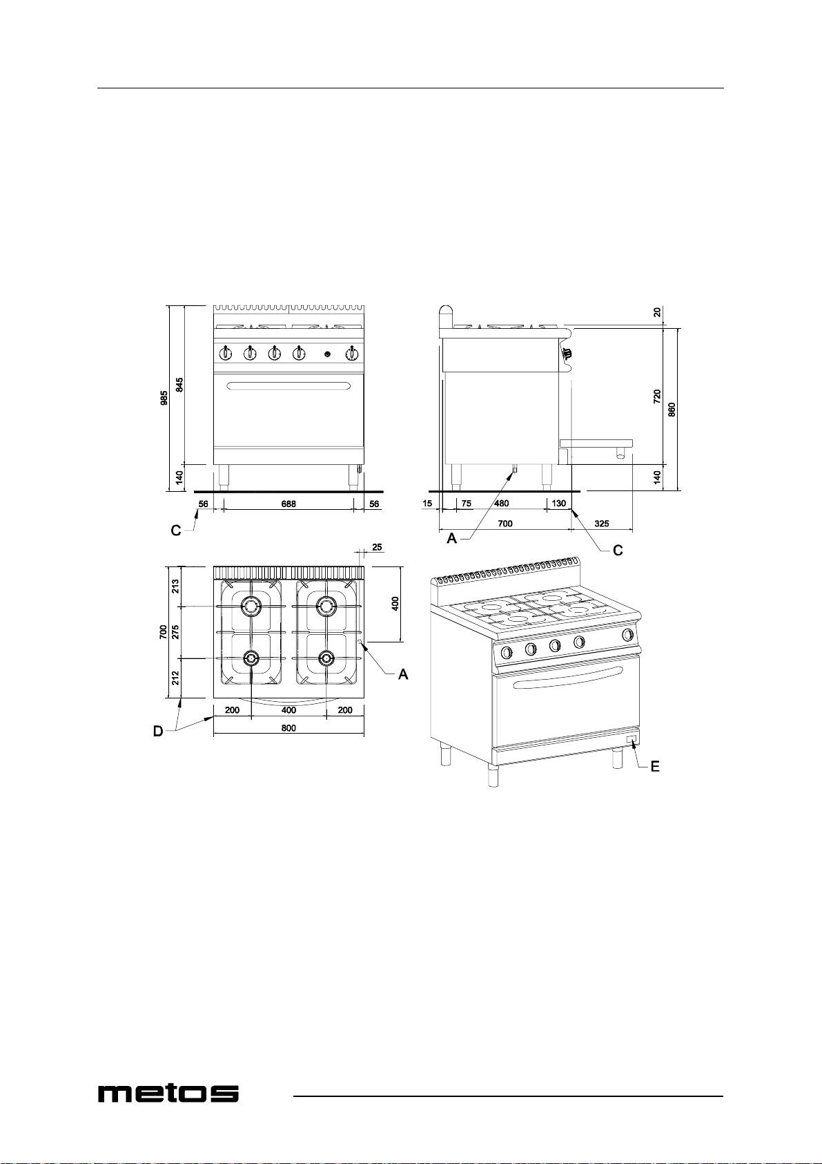
Installation and connection drawing 74/02CGG
78
Page 61
Technical specifications
2.9.2003 Rev. 1.0
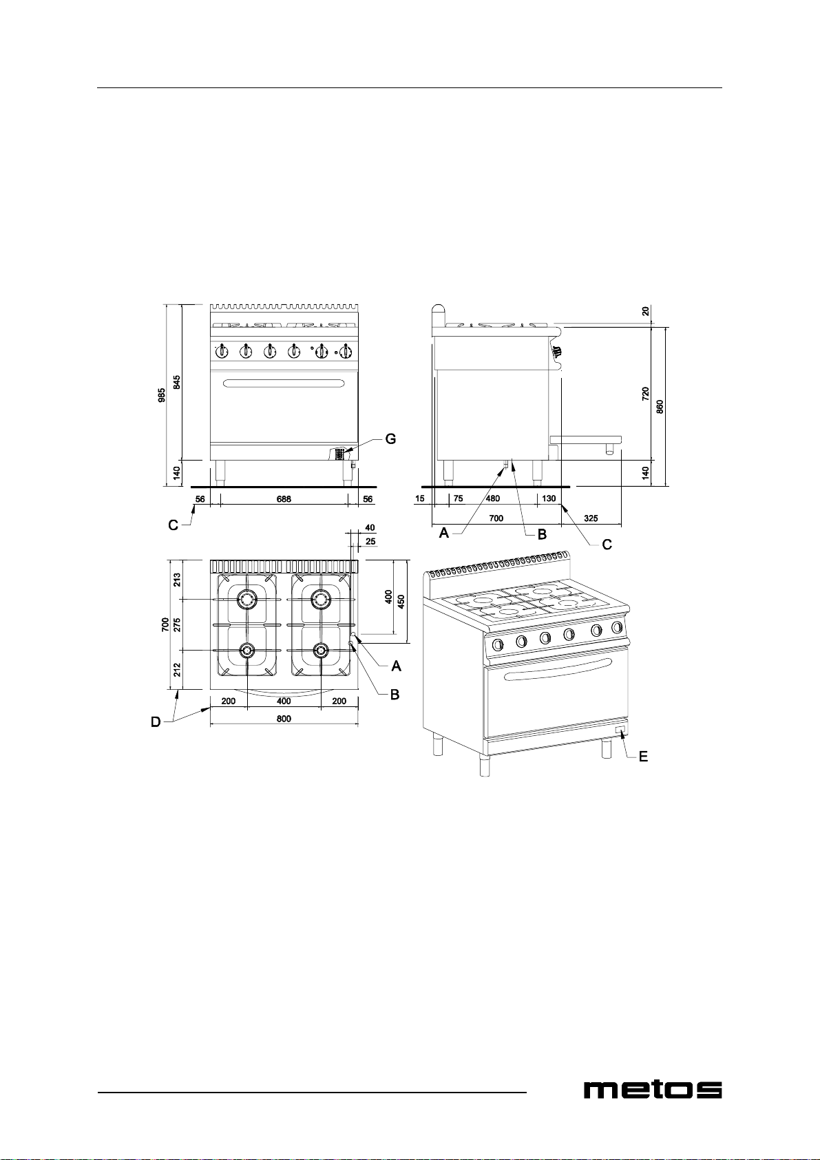
Installation and connection drawing 74/02CGE
79
Page 62
Technical specifications
2.9.2003 Rev. 1.0
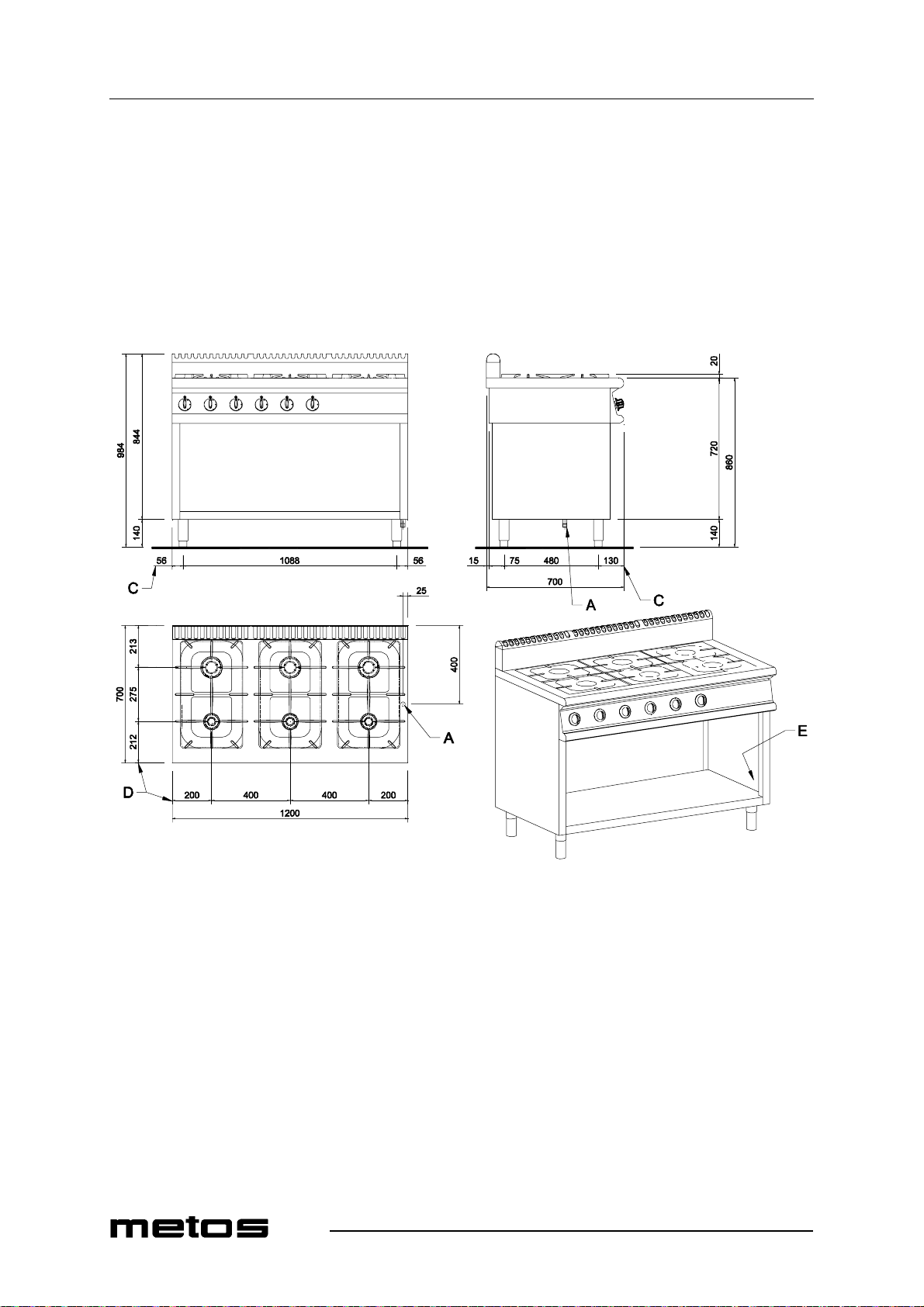
Installation and connection drawing 76/02CG
80
Page 63
Technical specifications
2.9.2003 Rev. 1.0
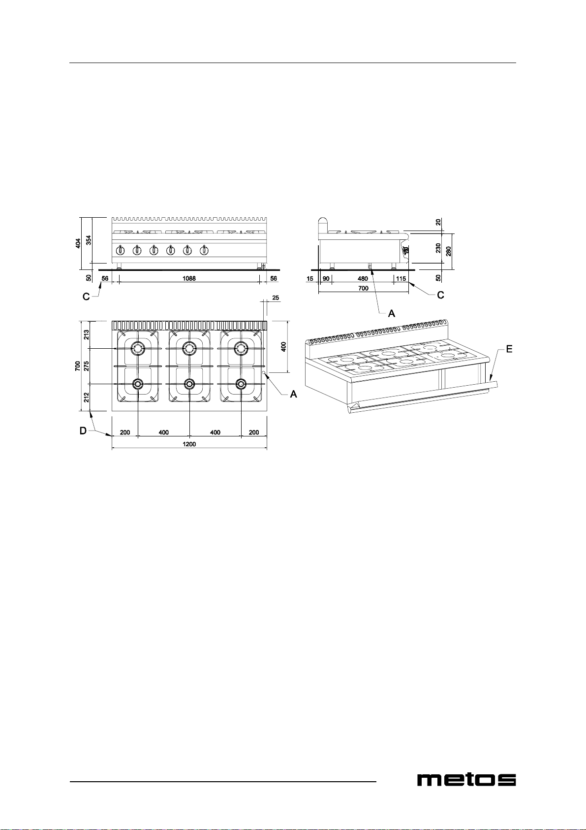
Installation and connection drawing 76/02TCG
81
Page 64
Technical specifications
2.9.2003 Rev. 1.0
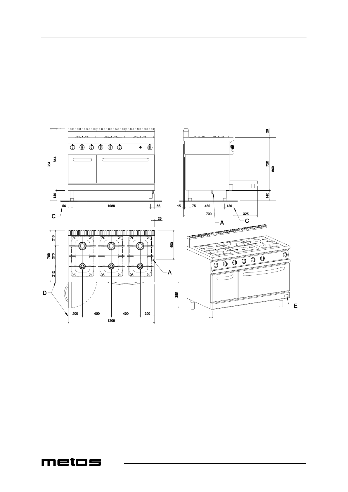
Installation and connection drawing 76/02CGG
82
Page 65
Technical specifications
2.9.2003 Rev. 1.0
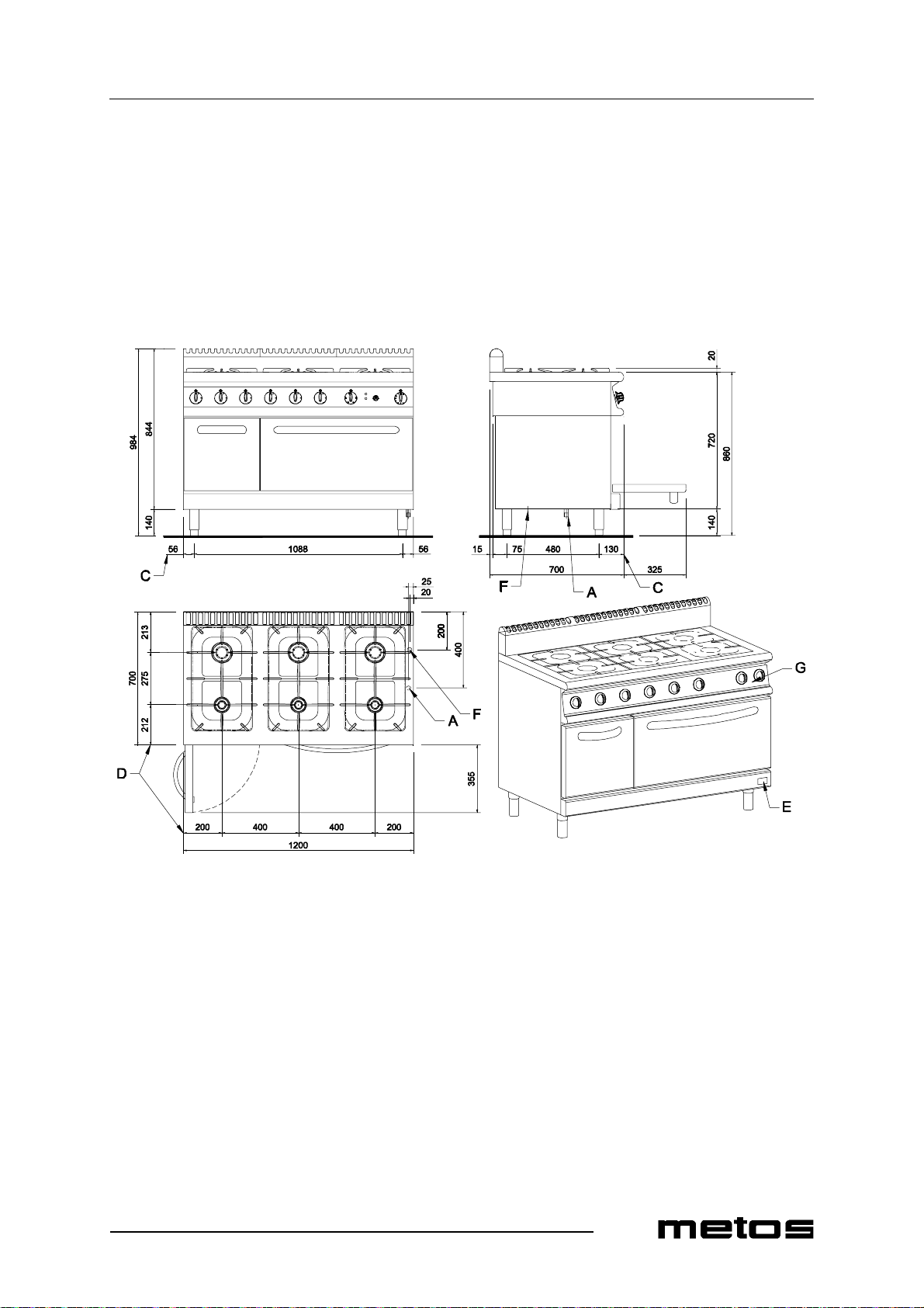
Installation and connection drawing 76/02CGGE
83
Page 66
Technical specifications
2.9.2003 Rev. 1.0
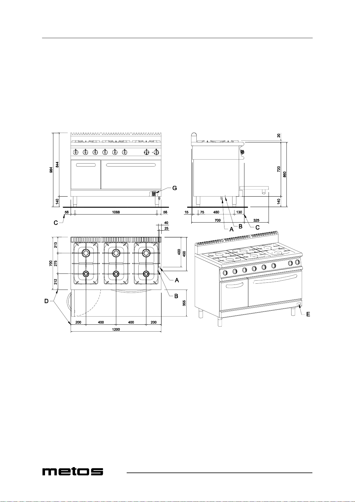
Installation and connection drawing 76/02CGE
84
Page 67
Technical specifications
2.9.2003 Rev. 1.0
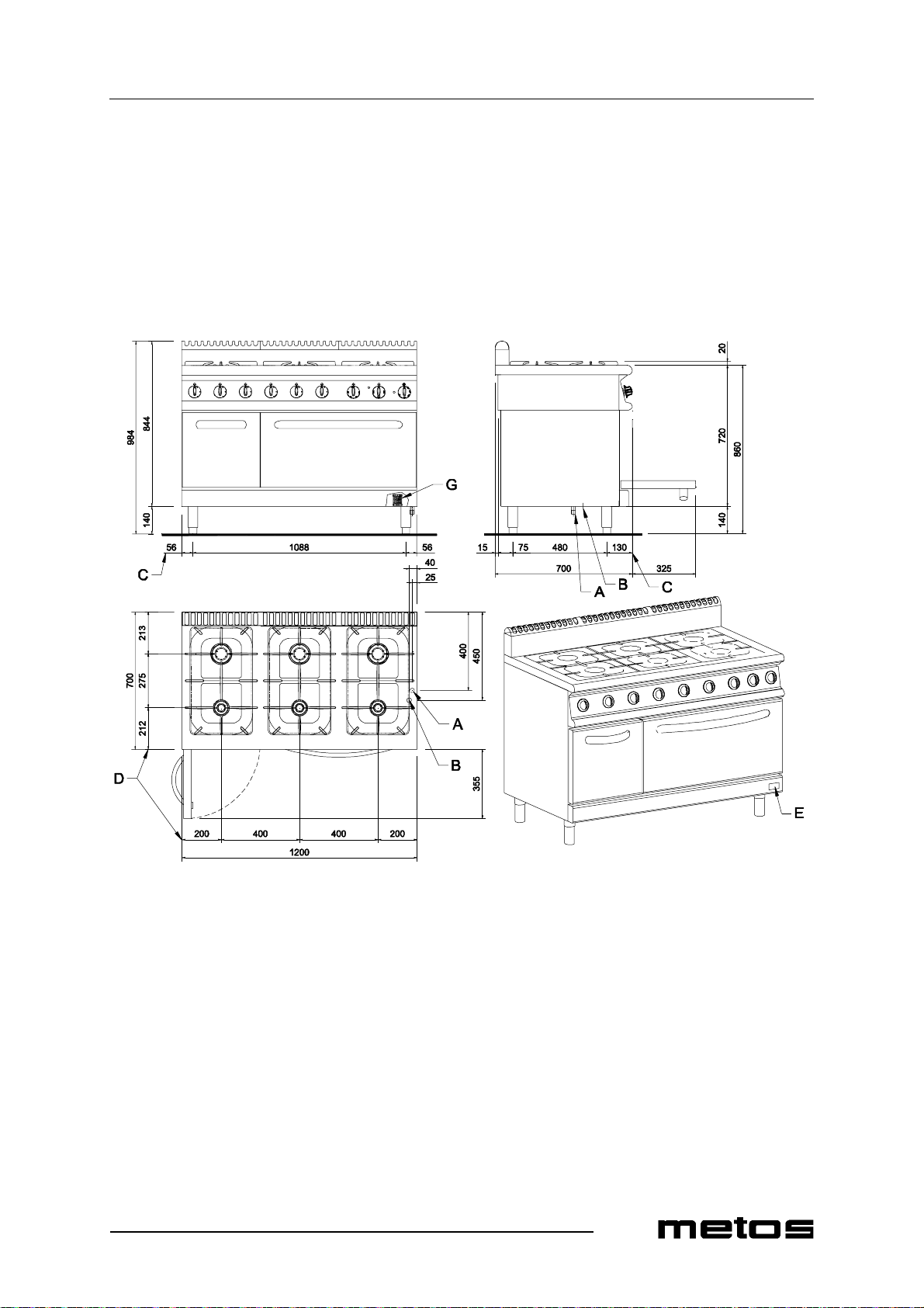
Installation and connection draw ing 76/02CGEE
85
Page 68
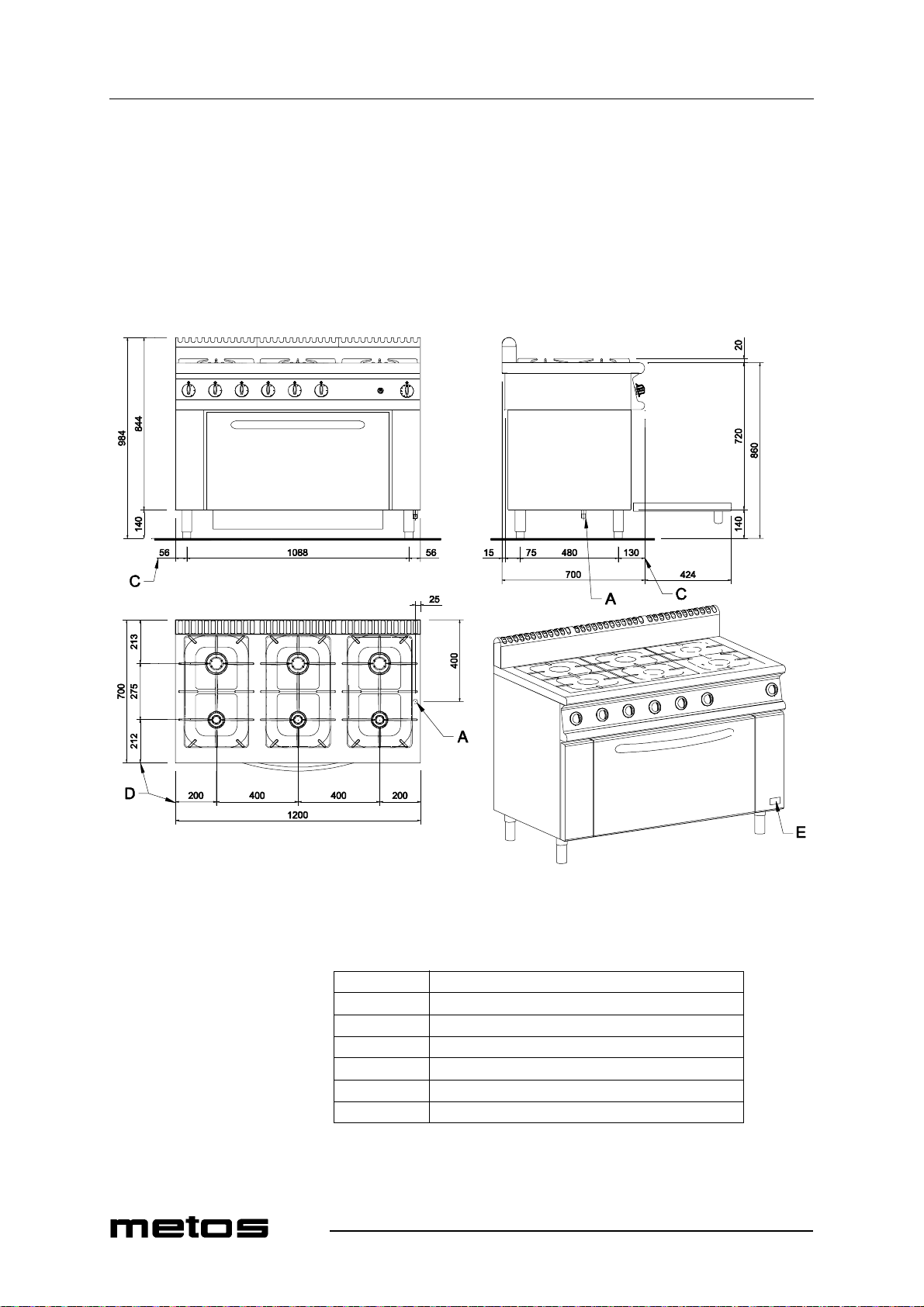
Technical specifications
2.9.2003 Rev. 1.0
Installation and connection drawing 76/02CGFL
86
A
B
C
D
E
F
G
Gas supply connection
Connection cable entry
Distance between feet
Distan ce between burners
Rating plate
Hot cupboard connection cable entry
Terminal block
Page 69

2.9.2003 Rev. 1.0
Technical specifications
Item Model Type Voltage Specification
External dime nsions WxDxH, fre estandi ng unit CG 72 400x700x860 /900 mm
External dime nsions WxDxH, fre estan ding unit 74, 74G, 74E, 74ST,
74STG, 74STE
External dime nsions WxDxH, fre estandi ng unit 76, 76G, 76GE, 76E,
76EE, 76FL, 76ST,
76STG, 76STGE
External dimensions WxDxH, tabletop unit CG 72T 400x700x280 mm
External dimensions WxDxH, ta bletop unit 74T, 74STT 800x700x280 mm
External dimensions WxDxH, tabletop unit 76T, 76STT 1200x700x280 mm
800x700x860 /900 mm
1200x700x86 0/900 mm
Inner oven dimensions 74G, 74E, 76G, 76G E,
76E, 76EE, 74STG,
74STE, 76STG, 76STGE
Inner oven dimensions CG 76FL 790x405x543 mm
Inner cupboard dimensions 76G, 76GE, 76E, 76EE,
76STG, 76STGE
Volume with package CG 72 0. 43 m ³
Volume with package 74, 74G, 74E, 74ST,
74STG, 74STE
Volume with pac kage 76, 76G, 76GE, 76E,
76EE, 76FL, 76ST,
76STG, 76STGE
Volume with package CG 72T 0.16 m³
Volume with pac kage 74T, 74STT 0.29 m³
Volume with package 76T, 76STT 0.42 m³
Total w ei g ht CG 72 50 Kg
Total weight CG 74 80 Kg
Total w ei g ht CG 76 105 Kg
Total weight CG 74E 135 Kg
Total w ei g ht CG 74G 140 Kg
Total weight CG 76E 170 Kg
Total w ei g ht CG 76EE 171 Kg
Total weight CG 76G 175 Kg
Total w ei g ht CG 76GE 176 Kg
Total weight CG 76FL 182 Kg
Total w ei g ht CG 72T 33 Kg
Total weight CG 74T 53 Kg
Total w ei g ht CG 76T 70 Kg
660x300x543 mm
300x331x550 mm
0.8 m³
1.18 m³
Electric oven pow er 74E, 76E, 76EE, 74STE 5.5 kW
Electric cup board power 76GE, 76EE, 76STGE 0.42 kW
Rated output 74E, 76E, 74STE 5.5 kW
Rated output CG 76EE 5.92 kW
87
Page 70

2.9.2003 Rev. 1.0
Technical specifications
Item Model Type Voltage Specification
Rated output 76GE, 76STGE 0.42 kW
Max. current CG 74E, 76E A 8.1 A
Max. current CG 74E, 76E H 14.5 A
Max. current CG 76GE P 1.8 A
Max. current CG 76EE A 9.9 A
Max. current CG 76EE H 15.8 A
Cable cross section CG 74E, 76E A 5 x 1.5 mm²
Cable cros s section CG 74E, 76E H 4 x 2.5 mm²
Cable cross section CG 76GE P 3 x 1.5 mm²
Cable cros s section CG 76EE A 5 x 1.5 mm²
Cable cross section CG 76EE H 4 x 2.5 mm²
Supply voltage 74E, 76E, 76EE, 74STE A 3/N/PE ~400V 50Hz
Supply voltage 74E, 76E, 76EE, 74ST E H 3/PE ~230V 50Hz
Supply voltage 76GE, 76STGE P 1/N/PE ~230V 50Hz
Gas burnes 72, 72T, 76ST, 76STG,
76STTG
Gas burnes CG 74, 74T, 74G, 74E 2x3.5 kW + 2x5.6 kW
Gas burnes CG 76, 76T, 76G, 76GE, 76E,
76EE, 76FL
Heat gas oven 74G, 76G, 76GE, 74STG,
76STG, 76STGE
Heat gas oven CG 76FL 8 kW
Gas power CG 72, 72T 9.1 kW
Gas power CG 74, 74T, 74E 18.2 kW
Gas power CG 76, 76T, 76E, 76EE 27.3 kW
Gas power CG 74G 26.1 kW
Gas power CG 76G, 76GE 35.2 kW
Gas power CG 76FL 35.3 kW
Air requirement for combustion CG 72, 72T 18.2 m³/h
Air requirement for combustion CG 74, 74T, 74E 36.4 m³/h
Air requirement for combustion CG 76, 76T, 76E, 76EE 54.6 m³/h
Air requirem ent for combustion CG 74G 52.2 m³/h
Air requirement for combustion CG 76G, 76GE 70.4 m³/h
Air requirem ent for combustion CG 76FL 70.6 m³/h
1x3.5 kW + 1x5.6 kW
3x3.5 kW + 3x5.6 kW
7.9 kW
Constructi on type CG A
Gas inlet 1/2" G ISO R7
88
Page 71
DICHIARAZIONE DI CONFORMITÀ CE
CE CONFORMITY DECLARATION
DECLARATION DE CONFORMITE CE
CE KONFORMITÄTSERKLÄRUNG
DECLARACIÓN DE CONFORMIDAD CE
Si dichiara che il seguente apparecchio:
We declare that the following equipment:
Nous déclarons que l'appareil suivont:
Wir erklären, dass dieses Gerät:
Se declara que el siguiente aparato:
Cucina a gas serie 700 New
Gas ranges series 700 New
Cousinieres a gaz gamme 700 New
Gas-Allgasherde serie 700 New
Cocina a gas gama 700 New
Mod.: 72/02CG, 74/02CG, 76/02CG, 74/02CGG, 74/02CGE, 76/02CGG,
76/02CGGE, 76/02CGE, 76/02CGEE, 76/02CGFL, 72/02TCG, 74/02TCG,
76/02TCG
è conforme alla direttiva 90/396 CEE
is in specification with the directiv e 90/396 CEE
est conforme aux directiv es 90/396 CEE
entspricht die 90/396 CEE Richtlinie
esta conforme las directrices 90/396 CEE
Certificato CE AFNOR Nr. 3842 del 15-01-2003 e successive revisioni
AFNOR CE certificate Nr. 3842 on 15-01-2003 and subsequent revisions
Certificat CE AFNOR Nr. 3842 du 15-01-2003 et révisions suivantes
AFNOR CE Certificat Nr. 3842 vom 15-01-2003 und darauffolgende Revisionen
Certificado CE AFNOR Nr. 3842 con fecha 15-01-2003 y siguientes revisiones
Bribano, 20/03/03
OLIS S.p.A.
Amministratore Delegato
P. Candiago
OLIS S.p.A.
IMPIANTI PER LA RISTORAZIONE
32030 BRIBANO - Belluno - Italy
Via Cavalieri di Vittorio Veneto, 14
Telefono +39-437-8558 (5 linee r.a.)
Fax +39-0437- 838274
http://ww.olis.it e-mail:[email protected]
Cap. Soc. € 2.500.000.
Registro delle Imprese 00917220256 R.E.A. n. 82605
Codice Fiscale e Partita IVA IT 009177220253
Page 72

 Loading...