

Page 1
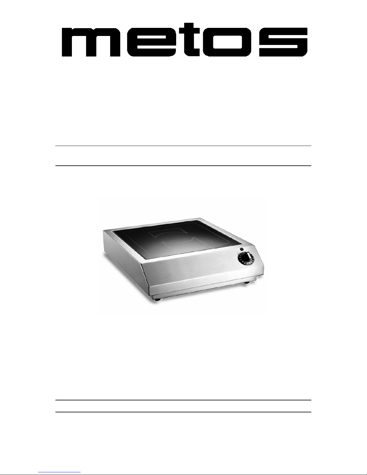
BASE-LINE INDUCTION RANGES
B
ase-Line
TYPE: 2500, 3500, 3500D, 5000, 5000D
Installation and Operation Manual
S/N: Rev.: 2.0
Page 2

Page 3

11.3.2003 Rev. 2.0
Dear Customer,
Congratulations on deciding to choose a Metos appliance for your kitchen activities. You
made an excellent choice. We will do our best to make you a satisfied Metos customer
like thousands of customers we have around the world.
Please read this manual carefully. You will learn correct, safe and efficient working methods in order to get the best possible benefit from the appliance. The instructions and hints
in this manual will give you a quick and easy start, and you will soon note how nice it is
to use the Metos equipment.
All rights are reserved for technical changes.
You will find the main technical data on the rating plate fixed to the equipment. When you
need service or technical help, please let us know the serial number shown on the rating
plate. This will make it easier to provide you with correct service.
For your convenience, space is provided below for you to record your local Metos service
contact information.
METOS TEAM
Metos service phone number:...............................................................................................
Contact person:....................................................................................................................
Page 4

11.3.2003 Rev. 2.0
Page 5

11.3.2003 Rev.
1. General .......................................................................................................... 1
1.1 Symbols used in the manual .......................................................................................... 1
1.2 Symbols used on the appliance ...................................................................................... 1
1.3 Checking the relationship of the appliance and the manual .......................................... 1
2. Safety .............................................................................................................. 3
2.1 Safe use of the appliance ............................................................................................... 3
2.1.1 Changing the settings and adjustments .................................................................. 4
2.2 Safety instructions in case of a malfunction .................................................................. 4
2.3 Disposal of the appliance ............................................................................................... 4
2.4 Other prohibitions .......................................................................................................... 4
3. Functional description .................................................................................. 5
3.1 Construction .................................................................................................................. 5
4. Operation instructions ................................................................................. 6
4.1 Before using the appliance ............................................................................................ 6
4.1.1 Operating test ......................................................................................................... 6
4.2 Operation procedures ..................................................................................................... 7
4.3 After use ........................................................................................................................ 7
4.3.1 Cleaning ................................................................................................................ 7
4.3.2 Periodic service ...................................................................................................... 8
4.3.3 Out of operation .................................................................................................... 8
5. Installation ..................................................................................................... 9
5.1 Preparing the installation ............................................................................................... 9
5.2 Installation ................................................................................................................... 10
5.3 Positioning the appliance ............................................................................................. 10
5.4 Electrical connections .................................................................................................. 11
5.4.1 Single phase supply ............................................................................................. 11
5.4.2 Three phase supply .............................................................................................. 11
5.5 After the installation .................................................................................................... 12
6. Troubleshooting .......................................................................................... 13
Page 6

11.3.2003 Rev.
8. Technical specifications .............................................................................. 27
Page 7
11.3.2003 Rev. 2.0
General
1
1. General
Carefully read the instructions in this manual as they contain important information regarding proper, efficient and safe installation, use and maintenance of the appliance.
Keep this manual in a safe place for eventual use by other operators of the appliance.
The installation of this appliance must be carried out in accordance with the manufacturer’s instructions and following local regulations. The connection of the appliance to the
electric and water supply must be carried out by qualified persons only.
Persons using this appliance should be specifically trained in its operation.
Switch off the appliance in the case of failure or malfunction. The periodical function
checks requested in the manual must be carried out according to the instructions. Have the
appliance serviced by a technically qualified person authorized by the manufacturer and
using original spare parts.
Not complying with the above may put the safety of the appliance in danger.
1.1 Symbols used in the manual
This symbol informs about a situation where a safety risk might be at hand. Given instructions are mandatory in order to prevent injury.
This symbol informs about the right way to perform in order to prevent bad results, appliance damage or hazardous situations.
This symbol informs about recommendations and hints that help to get the best performance out of the appliance.
This symbol informs about a function that has to be taken into account in self-control.
1.2 Symbols used on the appliance
This symbol on a part informs about electrical terminals behind the part. The removal of
the part must be carried out by qualified persons only.
1.3 Checking the relationship of the appliance and the manual
The rating plate of the appliance indicates the serial number of the appliance. If the manuals are missing, it is possible to order new ones from the manufacturer or the local rep-
Page 8

11.3.2003 Rev. 2.0
General
2
resentative. When ordering new manuals it is essential to quote the serial number shown
on the rating plate.
Page 9

11.3.2003 Rev. 2.0
Safety
3
2. Safety
2.1 Safe use of the appliance
The induction cookers Base-Line are specially suitable as cookers in the kitchen or for the
preparation of meals on the table. A cooker can be used for cooking, warming up, keeping
warm, flambéing, roasting, etc. food. The cooking or finishing process with Base-Line induction appliances must be carried out with recommended types and sizes of pans. Do not
use any NO NAME pans.
Information signs mounted directly on the cooker must be observed at all times and kept
in a fully legible condition.
Danger for persons, for the environment and for the cooker can result of non-observance
of the safety information. Certain risks may be associated with non-observance of precautions, including:
• Danger to persons through electrical causes
• Danger to persons through overheated pans
• Danger to persons through an overheated cooking platform (ceran plate)
The safety information contained in these instructions for use, the existing national regulation for the prevention of accidents as well as any internal working, operating and safety
regulation stipulated by the operator must be observed.
Any risks from electric power must be eliminated. The induction unit shall only be used
if the installation of the electricity is fitted by an approved installation contractor in accordance with specific national and local regulations.
• The heating area is warmed up from the heat of the pan. To avoid injuries (burning)
do not touch the heating area.
• To avoid overheating of pans by means of evaporating the contents, don’t heat up
pans unattended.
• Switch the control knob off if you take the pan away for a while. This will avoid
having the heating process continue automatically when a pan is placed back on
the heating area. So, if any person starts to use the cooker, he/she will have to start
the heating process by turning the control knob in the ON-position.
• Do not insert any piece of paper, cardboard, cloth, etc. between the pan and the
heating area, as this might initiate a fire.
• As metallic objects are heated up very quickly when placed on the operating heating area, do not place any other objects (closed cans, aluminium foil, cutlery, jewelry, watches etc.) on the induction cooker. Persons with a pacemaker should ask
their doctor whether they are safe near an induction cooker or not.
• Do not place credit cards, phone cards, cassette tapes, or other objects that are sensitive to magnetism on the ceran plate.
Page 10

11.3.2003 Rev. 2.0
Safety
4
• The induction cooker has an internal air-cooling system. Do not obstruct the air inlet-and air outlet-slots with objects (cloth). This would cause overheating and
therefore the cooker would switch off.
• Avoid liquid entering into the cooker. Do not let water or food overflow the pan.
Do not clean the cooker with a jet of water.
• If the heating area (ceran plate) is cracked or broken, the induction cooker must be
switched off and disconnected from the electric connection. Don’t touch any parts
inside the cooker.
2.1.1 Changing the settings and adjustments
Reconstruction of the cooker or changes to the cooker are not allowed. Contact the manufacturer if you intend to make any changes on the cooker. To guarantee the safety, only
use genuine spare parts and accessories authorized by the manufacturer. The use of other
components voids all warranties.
2.2 Safety instructions in case of a malfunction
Pans having a diameter smaller than 12 cm are not detected. During pan detection, the indicator operation flashes. No power is transferred and the indicator lamp flashes if no pan
or an unsuitable pan is detected.
The heating area is controlled with a temperature sensor. Overheated pans (hot oil, empty
pans) can be detected. Energy transfer will be stopped. The induction unit must be re-started after it has cooled down.
2.3 Disposal of the appliance
When the life cycle of the cooker ends, make sure that you safely dispose it. Avoid abuse:
The cooker may not be used by any person not having the appropriate qualifications.
Avoid that the cooker, provided for disposal, can be brought into operation. The cooker is
built up with common electrical, electromechanical and electronic parts. No batteries are
used. The operator is responsible for a proper and safe disposal of the cooker.
2.4 Other prohibitions
The operating reliability of the cookers can only be guaranteed with proper use. The limit
values may be exceeded on no account.
Page 11

11.3.2003 Rev. 2.0
Functional description
5
3. Functional description
3.1 Construction
Built in a robust method of construction, they are compact and powerful with a revolutionary technology in a complete case of CrNi-steel. Our accessories are coordinated with
the Base-Line“units. Equipped with continuos control, they allow efficient cooking.
• Simple operation with rotary switch with integrated mains switch
• Compact powerful electronics enable flat construction and safe operation
• A maximum of safety thanks to multiple functions of protection and checking
• Short cooking time
• Electronic checking of the energy supply
• Compact size – light weight
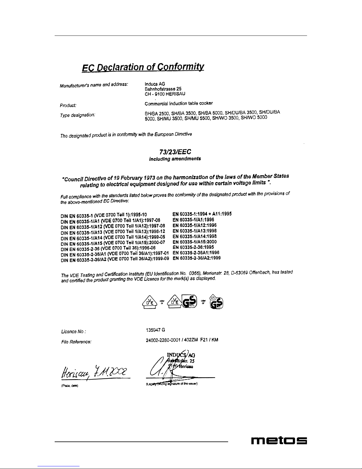
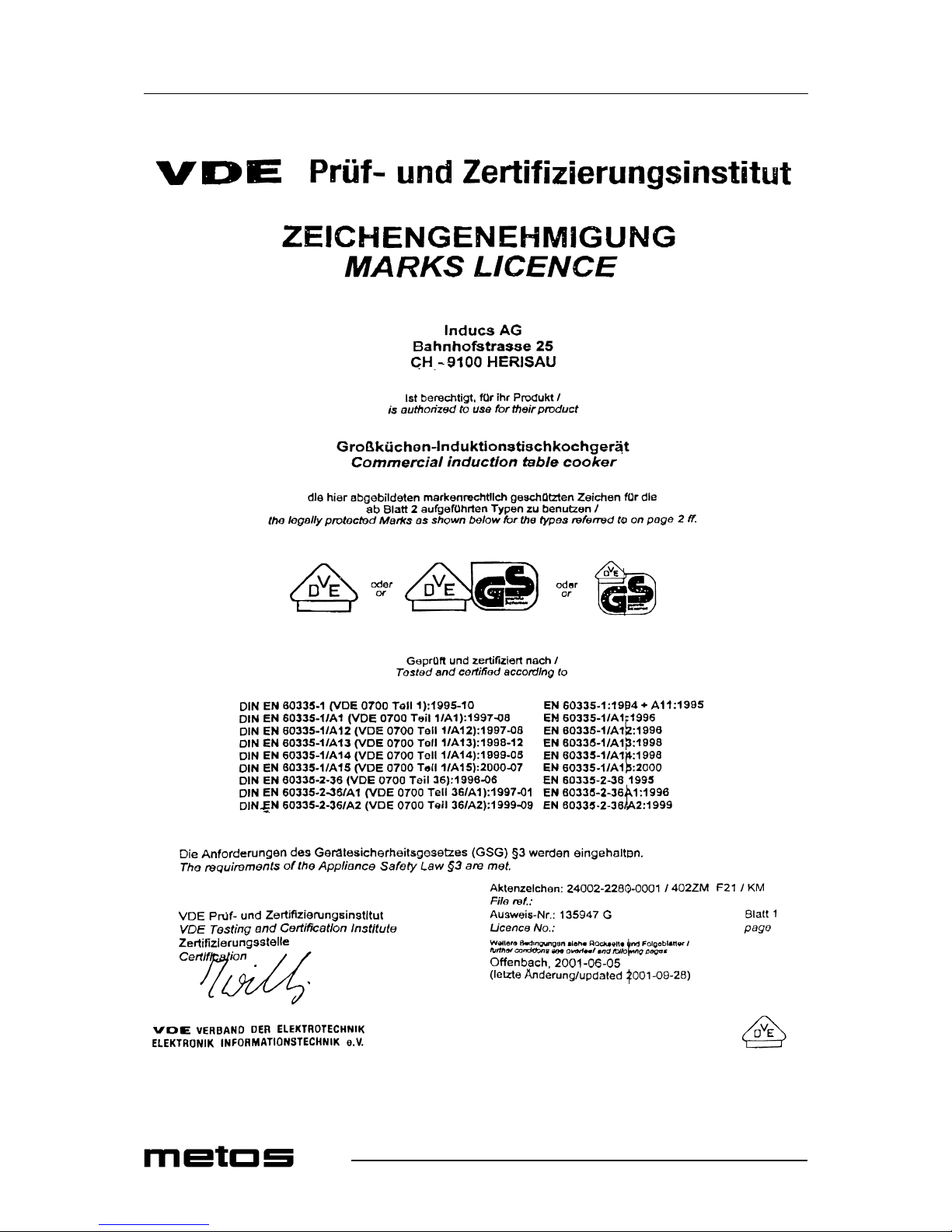
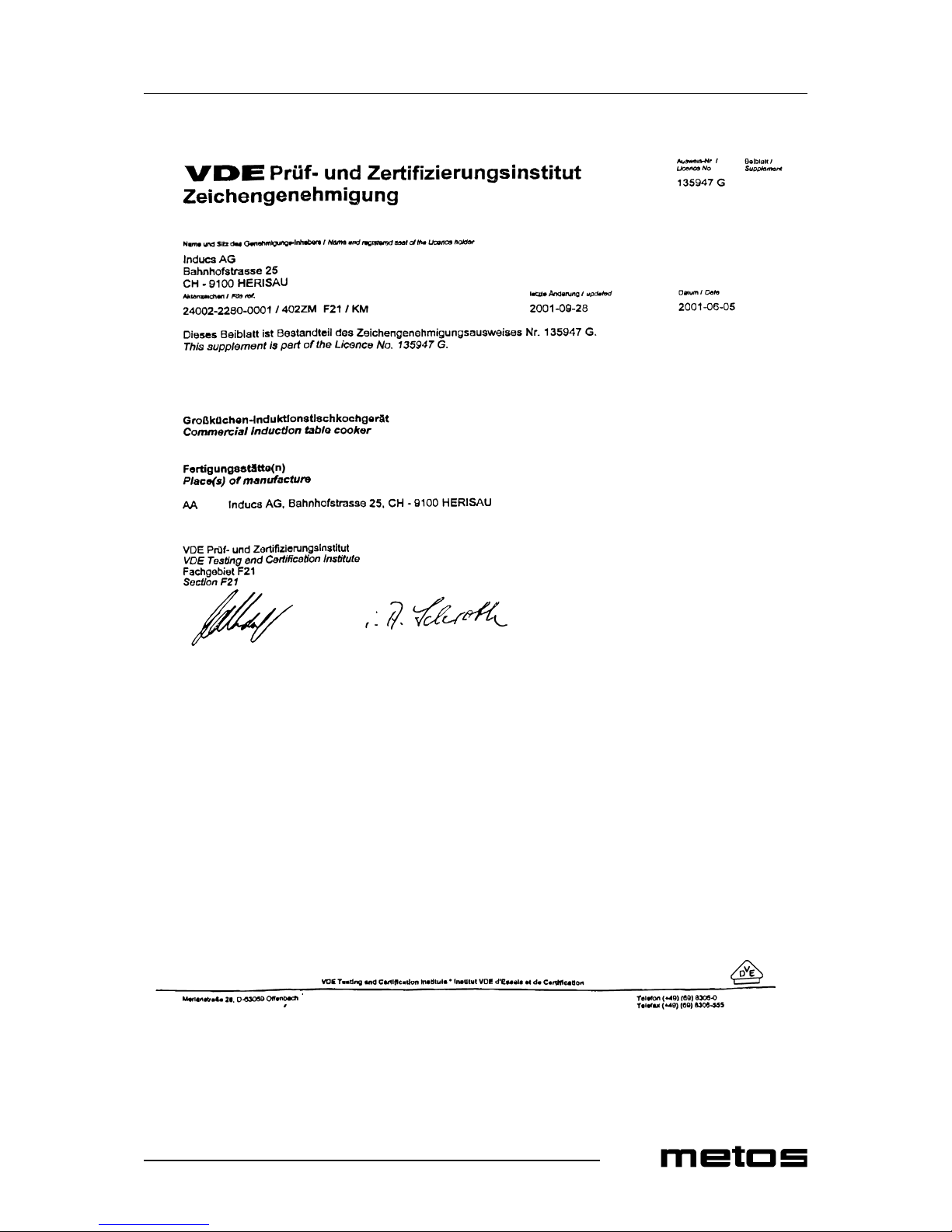
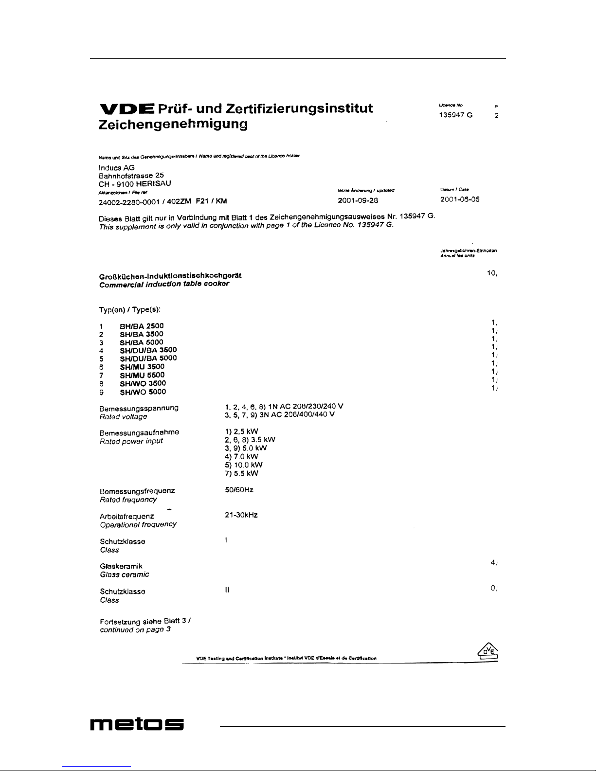
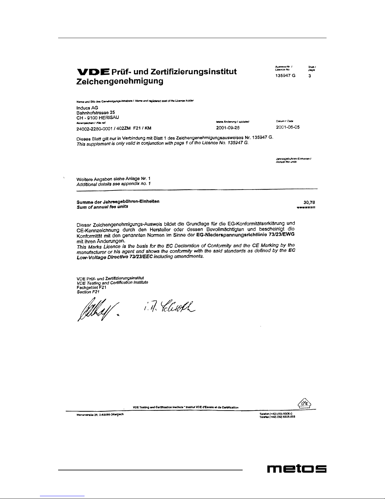
• Fulfills the latest directions: VDE EN 60335-1/-2/36, CE-conformingUL 197;
CAN/CSA/C 22.2 No. 109, NSF 4-1996
Page 12

11.3.2003 Rev. 2.0
Operation instructions
6
4. Operation instructions
4.1 Before using the appliance
4.1.1 Operating test
The glass ceramic cooking zone is warmed up from the heat of the pan. To avoid injuries
(burning) do not touch this area.
Use a pan that is suitable for induction cooking, having a bottom diameter of at least 12
cm.
• Put some water in the pan and place it in the center of the heating area.
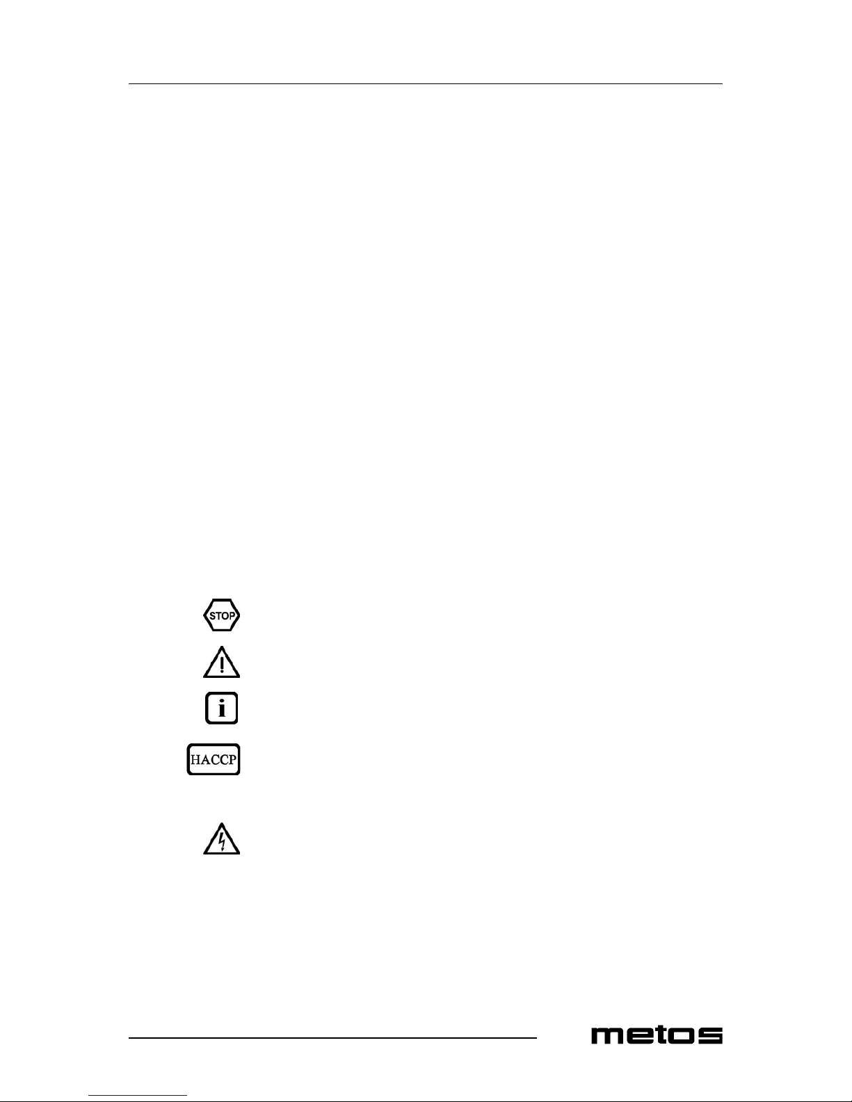
• Turn the control knob ON (in a position between 1 and 12). The indicator light
(green) illuminates and the water will be heated.
• Take the pan away from the heating area, the indicator light will flash
• Place the pan back on the heating area, the indicator light will illuminate and the
heating process will continue.
• Turn the control knob in the OFF-position, the heating process will stop, indicator
light turns off.
The shining indicator light operation means that energy is being transferred to the pan. If
the indicator operation remains off, check the following:
• Is the cooker connected to the power supply?
• Is the control knob in ON positon?
• Do you use a suitable pan (bottom diameter at least 12cm (5“), pan made of suitable material)?
• Is the pan placed in the center of the heating area?
To verify if the pan is suitable, use a permanent magnet and find out if it sticks to the bottom of the pan. If not, your pan is not suitable for induction cooking. Choose a pan which
is recommended for induction cooking. If in spite of all positive controls and tests the
cooker doesn’t work, refer to “Troubleshooting”.
Page 13

11.3.2003 Rev. 2.0
Operation instructions
7
4.2 Operation procedures
The induction cooker is switched on with the control knob. The cooker is immediately
ready for operation. The illuminated indicator lights mean that energy is being transferred
to the pan. The power rating is set by turning the control knob. The inductive power depends on the position of the potentiometer:
• position 1 > minimum power
• position 12 > maximum power
Due to the following characteristics, the operator must be more attentive when using the
induction cooker than it would be required with other appliances. The heat storage capacity of this system is very low. If the heating level is changed with the control knob, the
food is immediately exposed to a different temperature. Do not put empty pans on the
glass ceramic cooking zone, first put grease or liquid into the pan and start cooking process after that. Adjust carefully the heating level to the required cooking mode. Set and adjust the power with the control knob. The pan should always remain in the center of the
heating area, otherwise, the bottom of the pan is heated unequally and the food inside the
pan may burn. When heating up oil or grease, constantly check the pan to prevent oil and
grease from overheating and burning.
The cooker only transmits energy if a pan is placed on the heating area, independently of
the position of the control knob. If you take the pan away from the heating area, power
transfer stops immediately. If the pan is put back on the heating area, the selected power
will be transferred to the pan again. After switching the cooker to the off position the
cooking will stop.
4.3 After use
4.3.1 Cleaning
List with common types of soiling and recommendations how to treat them:
• Slight soiling, no burned residues: Wipe with a moist cloth, without cleaning agent
• Sticky soiling: Remove with a scraper. Then wipe the heating area with a moist
cloth
• Lime deposits, caused by water which has boiled over: These spots can be removed with vinegar or a special cleaning agent
• Sugar, sugar containing food, plastic, aluminum foil: Immediately scrape off the
sugar, plastic or aluminum foil residues thoroughly from the hot cooking area, e.g.
with a razor blade. After removal of the residues, clean it with a cleaning agent. If
the heating area soiled with residues of sugar, plastic or aluminum foil cools down
without prior cleaning, the ceramic surface might become deformed by pinheadsized pits
The cleaning of the Ceran plate and the ceramic bowl is identical to other similar surfaces
like glass. Do not use corrosive or abrasive cleaning agents, such as grill- and ovensprays, stain- and rust-removers, scouring powder and rough sponges. Before being
cleaned, the Ceran plate or the ceramic bowl must be cooled down. Other maintenance
and servicing work other than cleaning as described here, must be done by authorized
service personnel. Make sure that no liquid can enter in the induction unit.
Page 14

11.3.2003 Rev. 2.0
Operation instructions
8
4.3.2 Periodic service
A good maintenance of the induction cooker requires a regular cleaning, care and servicing. The operator has to ensure, that all components relevant for safety are in perfect
working order at all times. The cooker should be examined at least once a year by an authorized technician.
Do not open the cooker, dangerous electric voltage inside.
The cookers may only be opened by authorized personnel.
4.3.3 Out of operation
If the cooker is not in use, make sure that the control knob is in the “OFF” position. If you
don’t use the cooker for a longer period (several days) unplug the unit. Make sure that no
liquid can enter into the cooker and do not clean the cooker with a jet of water.
Page 15

11.3.2003 Rev. 2.0
Installation
9
5. Installation
5.1 Preparing the installation
Please observe the following rules:
• Check and ensure that the supply voltage matches the voltage given on the rating
plate
• The electrical connections must satisfy local house installation regulations. The
valid, national and local electrical regulations must be observed.
• This induction appliance is equipped with a cable which can be connected with the
necessary plug to the socket. The socket must be easily accessible to disconnect
the unit from the net.
• When faulty-current circuit breakers are used, they must be rated for a breaking
current of 30mA or more
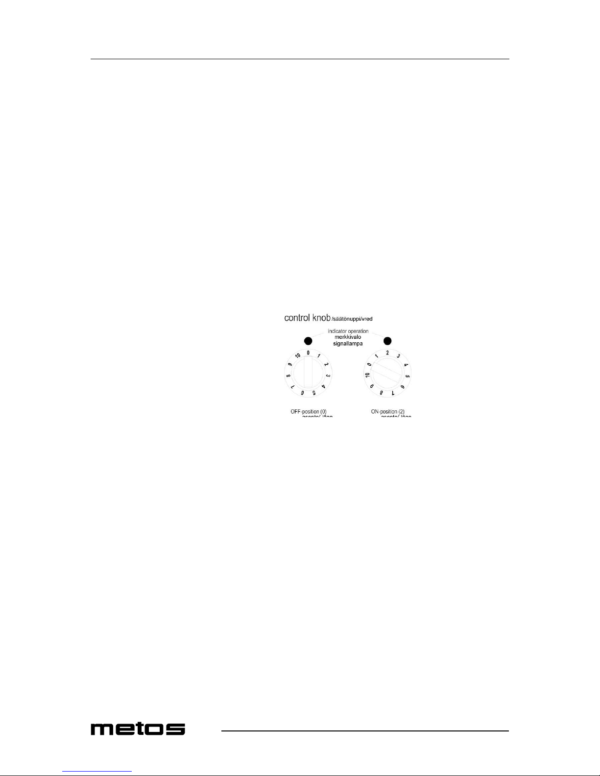
• This induction unit is equipped with an air cooling system. Make sure that the air
supply and air exhaust are not blocked (wall, fabric etc)
• This induction unit is equipped with an additional grease filter. Make sure that the
induction unit does not take in hot ambiant air (concerns units standing side by
side, or one behind the other, or standing near a frying pan or an oven)
• The induction unit must not be placed near or on a hot surface
• The air intake temperature must be under 40°C
• The operating staff has to make sure that installation is done by qualified personnel.
Page 16
11.3.2003 Rev. 2.0
Installation
10
5.2 Installation
The cooker is equipped with a cable. It has to be connected to a wall socket. If no plug is
installed at the cable, do the connection according to the information in “Electrical connections”. The installation for the electricity must be fitted by approved installation contractors in accordance with specific national and local regulations. The installation
contractors are responsible for the correct layout and installation in conformity with all
safety regulations. The warning signs and rating plates put up to the appliances must
strictly be followed. Check and ensure, that the mains voltage matches with the voltage
given on the rating plate.
The cooker must always be installed on a clean and even surface (table, base, etc.) at it’s
designated site. The cooker stands on non-slip rubber feet and is not permanently installed. It must be installed in such a way that it cannot fall down or move in a uneven
position. The conditions for the “positioning the appliance must be guaranteed.
Turn the control knob in the OFF-position before connecting the cooker with the voltage
supply. The operator has to insure that all installation, maintenance and inspection work
is carried out by authorized and qualified personnel.
When the control knob points to the “0”-position, the cooker is OFF. In any other position
the cooker is on.
5.3 Positioning the appliance
The cooker has to be installed on a even place like a table. It requires an area of at least
400 x 480 mm. The air inlet and air outlet must not be obstructed, the area must be able
to carry a loading of 40 kg. The cooker doesn’t have to be fixed on the table. The control
knob to operate the cooker must be easily accessible.
Installation ambience:
• Max. ambient temperature: Storage > -20 - +70°C, function> + 5 - +40°C
• Max. relative humidity of air: Storage > 10% - 90%, function> 30% - 90%
Page 17
11.3.2003 Rev. 2.0
Installation
11
5.4 Electrical connections
The electrical connection must be done by an authorized person.
5.4.1 Single phase supply
Induction appliance: Type Base-Line 2500 and type Base-Line 3500. The cooker is
equipped with a cable and plug conforming to the national regulations.
If the voltage is wrong, the cooker can be damaged.
• Voltage: +6 / -10%
• Frequency: 50 Hz / 60 Hz
• Preliminary fuse: 16A
5.4.2 Three phase supply
Induction appliance:Model Base-Line 5000, model Base-Line 5000D. The cookers are
equipped with a cable conforming to the national regulations.
Make sure that the plug is connected the right way:
• Phase 1,2,3: black / brown/blue (Colour of the conductor) or other colours, except
of grey, green or white
• Protective ground: green / yellow (Colour of the conductor)
If the voltage is wrong, the cooker can be damaged.
• Voltage: + 6 / -10 %
• Frequency: 50 / 60 Hz
• Preliminary fuse: 10A (5 kW), 10A (2x3,5 kW) 15A (2x5,0kW)
d: minimal distance to the wall = 4 c
air inlet
side view
air outlet
d
Induktioliesi/ induktionsspis
/sivulta/ från sidan
ilmanotto/ luftintag
ilmanlähtö/ luftutlopp
m
minimietäisyys seinään
minimiavstånd till väggen
Page 18
11.3.2003 Rev. 2.0
Installation
12
5.5 After the installation
Before carrying out function checks, the operator must know how to operate the cooker.
Your cooker is positioned in a suitable place and connected with the voltage supply. Make
sure that the cooker is well positioned and free from exposure to vibration. The control
knob is in the OFF-position.
Remove all objects from the glass ceramic cooking zone, verify if this area is neither
cracked nor broken. Don’t continue with use when the glass ceramic cooking zone is
cracked or broken, immediately switch off and disconnect the cooker from the socket.
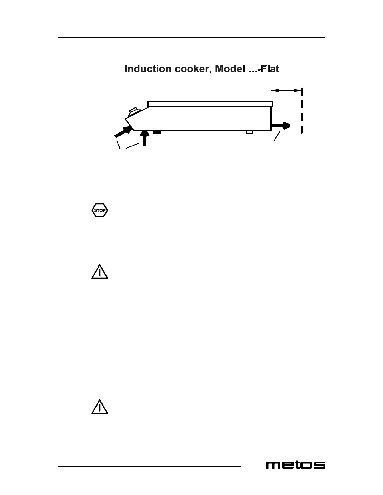
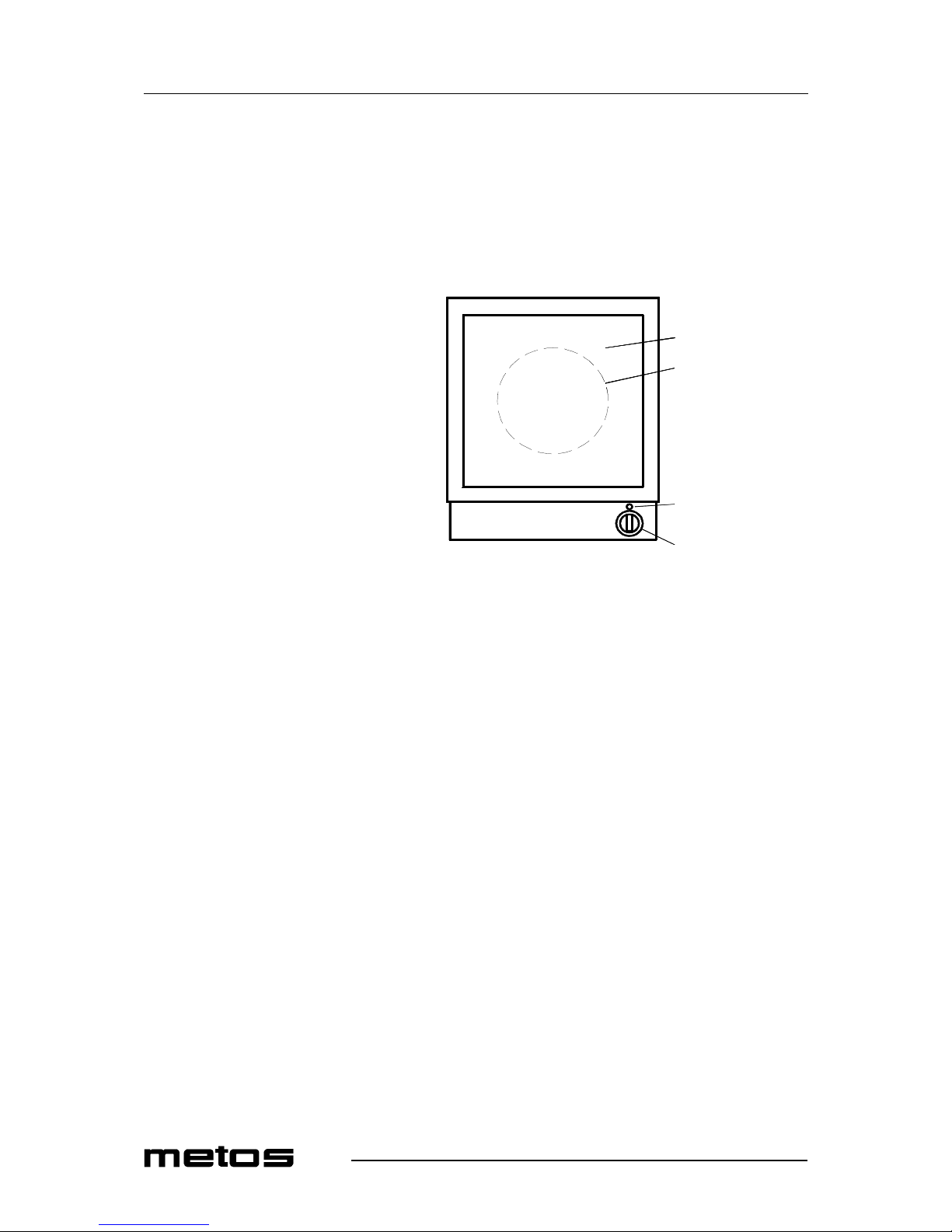
control knob
indicator operation
coil
heating area
Induction cooker
Model ...-Flat
top view
ylhäältä
uppifrån
lämmitysalue
värmeområde
käämi
spole
merkkivalo
signallampa
säätönuppi
vred
Page 19
11.3.2003 Rev. 2.0
Troubleshooting
13
6. Troubleshooting
Do not open the cooker, dangerous electric voltage inside.
The cookers may only be opened by authorized service personnel. Stop any actions if the
heating area (Ceran plate) is cracked or broken, the induction cooker must be switched off
and disconnected from the electric supply. Don’t touch any parts inside the cooker.
Error messages:
1. The induction unit stops working immediately.
2. The induction unit is still working with reduced power cycles.
3. Bad pan material
An error message consist of a long flash and a number of short flashes after the long one.
The number of the short flashes corresponds to the error code listed above.
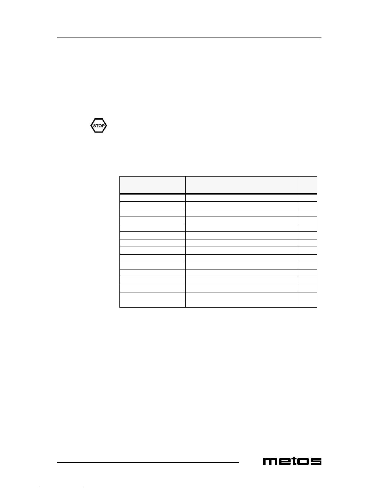
Number of flashing
signals -Code
Signification
-- No fault, normal operation
01 No coil current, Hardware overcurrent 3)
02 High coil current, Software overcurrent 3)
03 Temperature heat sink too high 1)
04 Temperature heating area too high 1)
05 Switch or potentiometer defected 1)
06 Too high inside temperature 2)
07 Coil temperature sensor, short circuit, short circuit 1)
08
09
10
11
12 Power reduction heat sink temperature 2)
13 Power reduction heating area temperature 2)
14 Power reduction caused by bad pan material 2)
Page 20
11.3.2003 Rev. 2.0
Troubleshooting
14
1)To verify, if the pan is suitable, use a permanent magnet and find out if it sticks on the
bottom of the pan. If not, your pan is not suitable for induction cooking. Choose a pan
which is recommended for induction cooking. Chose pan material suitable for induction
appliances.
2)The cooling-system (fan) starts to operate when the heat temperature exceeds 55ºC . At
heat temperatures higher than 70ºC, the controller automatically reduces the power to
keep the power unit in normal operating conditions. The cooker runs in a non continuous
mode. This mode can be heard.
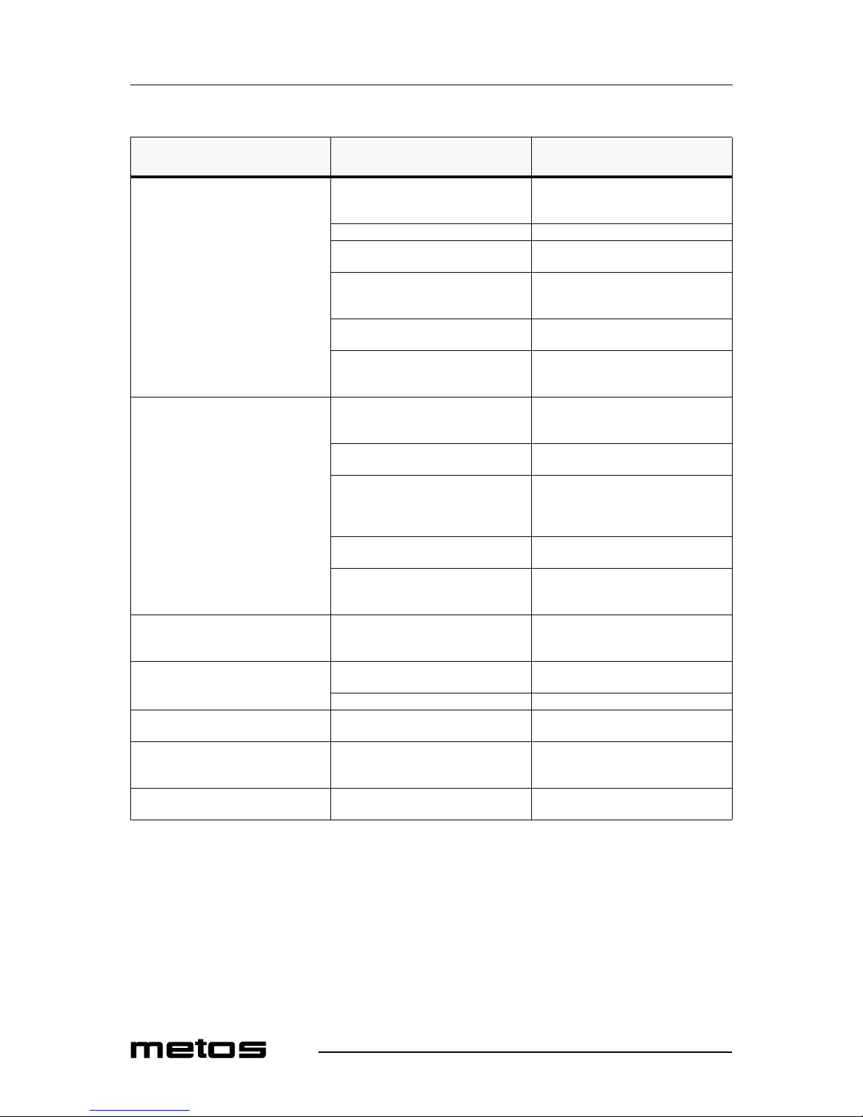
Fault Possible cause Action to take through opera-
tor or operating personell
No heating, operation indicator is OFF
(dark)
No mains supply Check the electrical supply (cable
plugged in the wall socket), check preliminary fuses
Control knob in OFF- position Turn control knob ON
Pan too small (bottom diameter less
than 12 cm)
Use a suitable pan
Pan is not placed in the center of the
heating area (the cooker can't detect the
pan)
Move the pan to the center of the heating area
Unsuitable pan Choose a pan which is recommended
for induction cooking 1)
Cooker defective• Ask your supplier for repair service,
unplug the cooker from the electrical
supply
Poor heating, operation indicator is
ON (shines) •
Used pan is not ideal Use a pan which is recommended for
induction cooking, compare results
with 'your' pan
Air-cooling system hindered Verify, that air inlet and air outlet are
not hindered with objects
Ambient temperature is too high (the
cooling system is not able to keep the
cooker in normal operatingconditions
2) )
Verify, that no hot air is sucked in by
the fan. Reduce the ambient temperature. The air inlet temperature must be
lower than 40ºC
One phase is missing (only with three
phase supply)
Check preliminary fuses
Cooker defective• Ask your supplier for repair service,
unplug the cooker from the electrical
supply
No reaction to control knob positions Control knob defective Ask your supplier for repair service,
unplug the cooker from the electrical
supply
Heating cycle switches off and on
within minutes, fan is active
Air inlet or outlet hindered Remove objects from air inlet and air
outlet slots, clean the slots
Grease filter is dirty Clean grease filter
Heating switches off and on within
minutes, fan is never active
Fan defective or fan control defective Call service
After a longer permanent operating
time, the heating switches off and on
within minutes
Coil overheated, cooking area too hot
or empty pan or pan with overheated
oil
Switch cooker off, remove pan and
wait until the cooking area has cooled
off.
Small metallic objects (e.g. spoon) are
heated up within the cooking area
Pan detection tuned incorrectly Call service!
Page 21

11.3.2003 Rev. 2.0
Technical specifications
27
8. Technical specifications
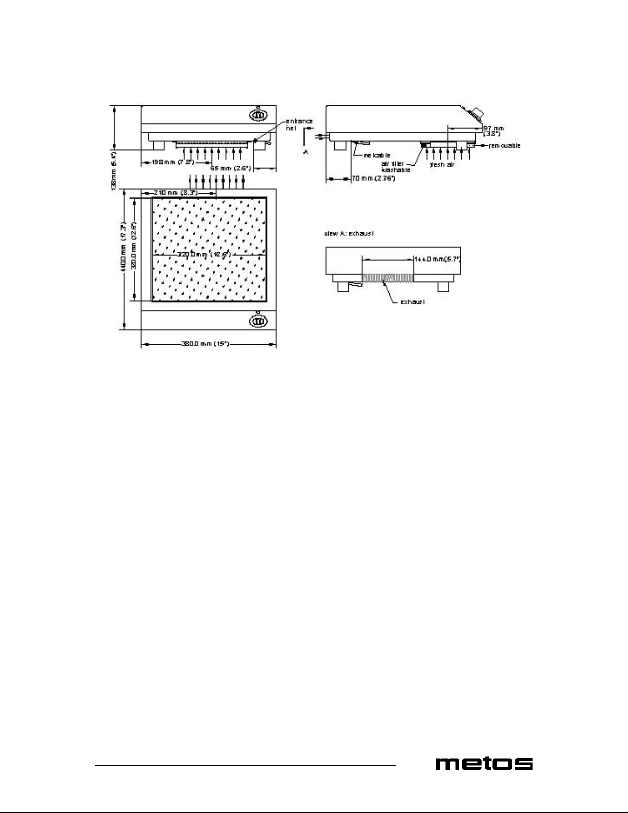
Installation drawing Base-Line 2500
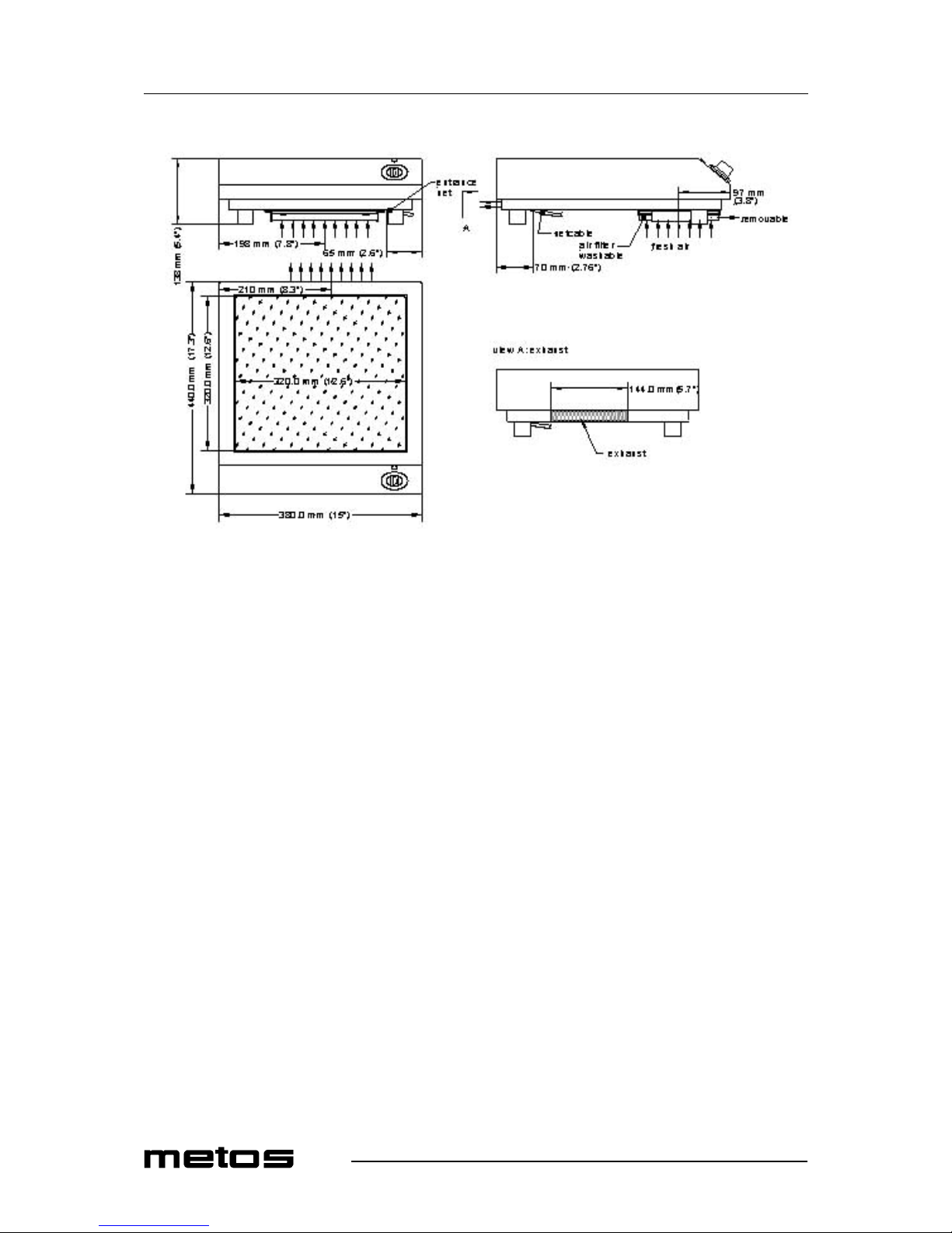
Installation drawing Base-Line 3500
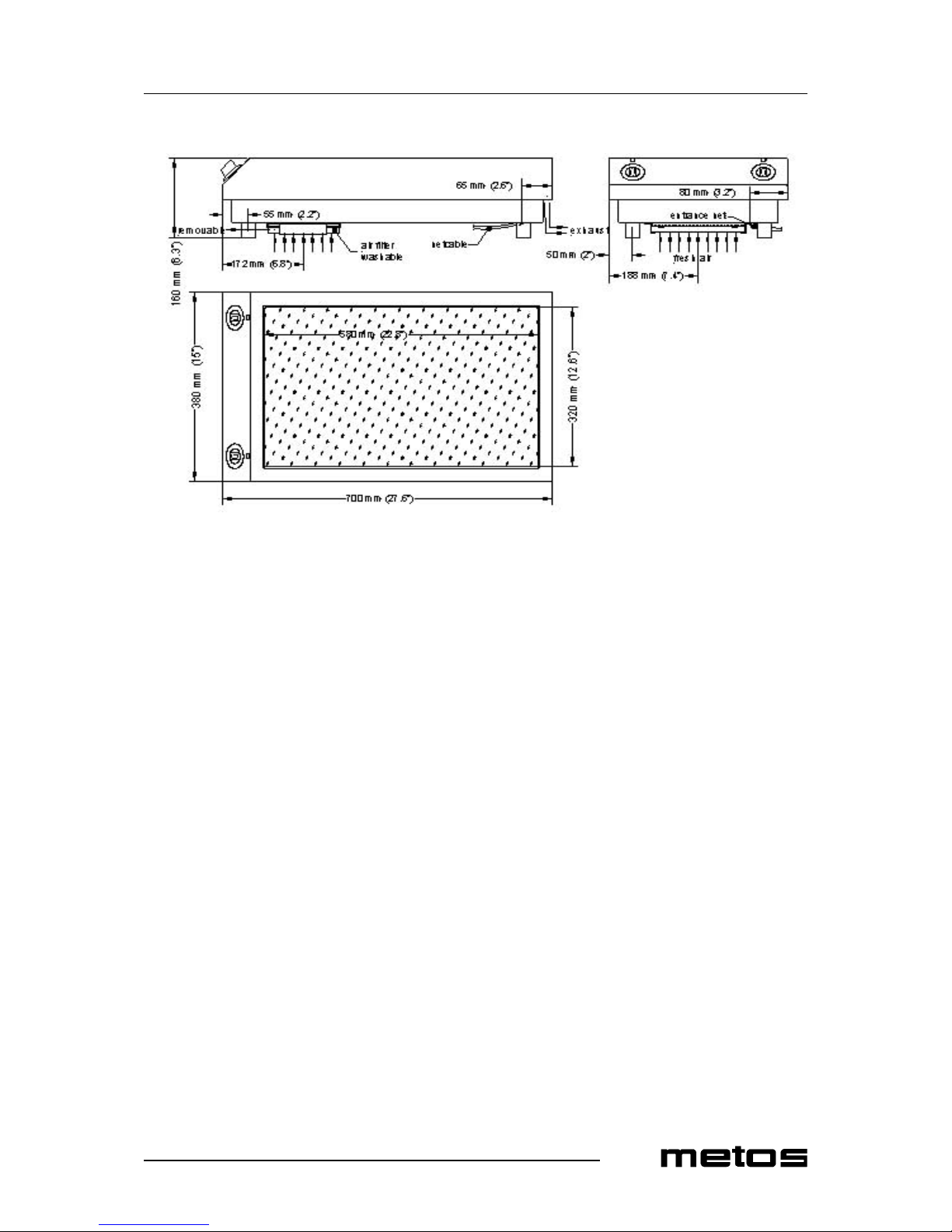
Installation drawing Base-Line 5000
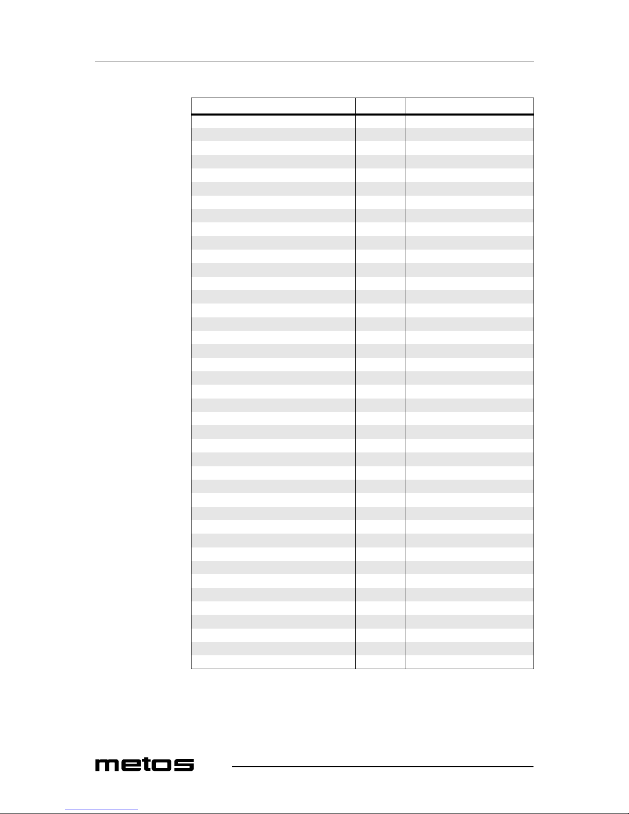
Installation drawing Base-Line 5000D
Page 22
11.3.2003 Rev. 2.0
Technical specifications
28
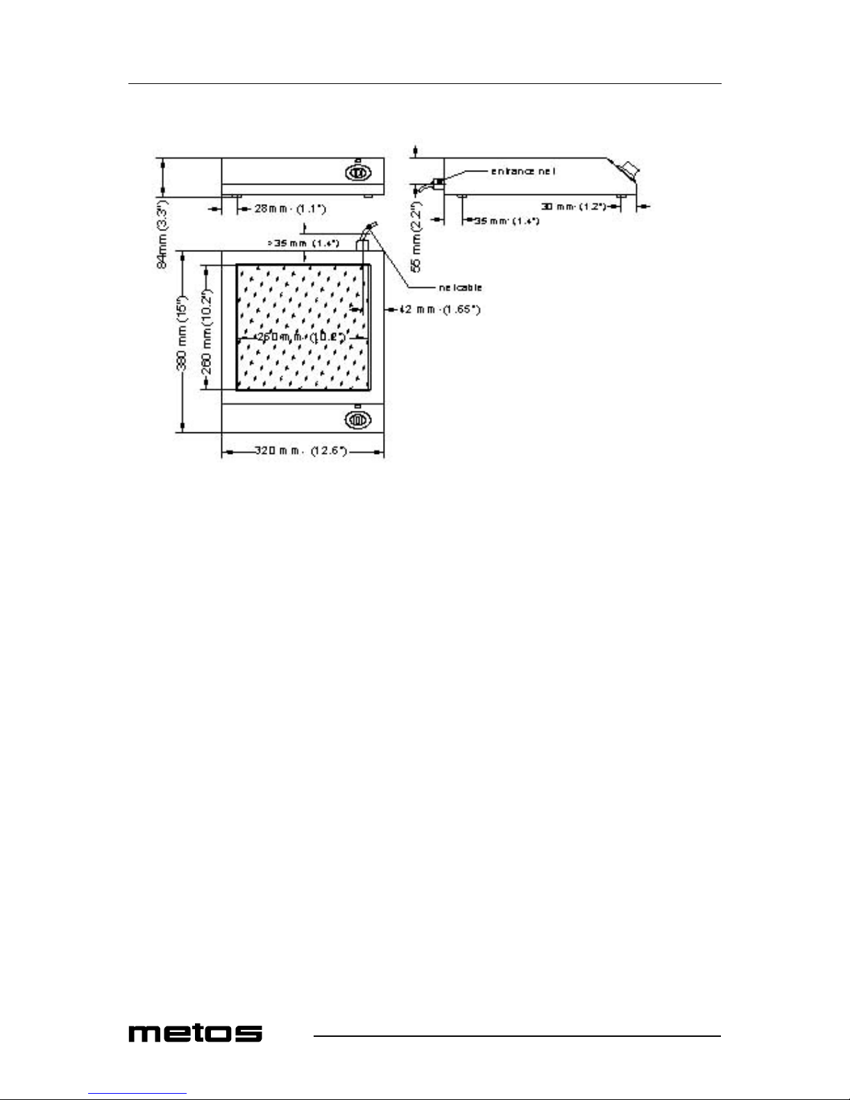
Installation drawing Base-Line 2500
Page 23
11.3.2003 Rev. 2.0
Technical specifications
29
Installation drawing Base-Line 3500
Page 24
11.3.2003 Rev. 2.0
Technical specifications
30
Installation drawing Base-Line 5000
Page 25
11.3.2003 Rev. 2.0
Technical specifications
31
Installation drawing Base-Line 5000D
Page 26
11.3.2003 Rev. 2.0
Technical specifications
32
Item Type Specification
Lamp operation 24V DC/max. 40mA (green)
Power regulation Potentiometer 10kOHM
Dimensions WxDxH 2500 320x380x90 mm
Dimensions WxDxH 3500, 5000 380x440x138 mm
Dimensions WxDxH 5000D 380x700x160 mm
Ceramic top 2500 260x260 mm
Ceramic top 3500, 5000 320x320 mm
Ceramic top 5000D 320x580 mm
Technical data
Voltage 2500 230
Voltage 3500 230
Voltage 5000 400
Voltage 5000D 400
Power 2500 2,5 kW
Power 3500 3,5 kW
Power 5000 5,0 kW
Power 5000D 2x5,0 kW
Current 2500 11,8A
Current 3500 16 A
Current 5000 14 A
Power factor 2500 >0.95
Power factor 3500 >0.95
Power factor 5000 >0.95
Discharge rate 2500 4 mA
Discharge rate 3500 4 mA
Discharge rate 5000 4 mA
Coil diameter 2500 190 mm
Coil diameter 3500 210 mm
Coil diameter 5000 210 mm
Weight 2500 9 kg
Weight 3500 11 kg
Weight 5000 11 kg
Weight 5000D 25,2 kg
Operation conditions
Max. tolerance of the nominal supply voltage 2500 +6/-10%
Supply frequency 2500 50/60 Hz
Protection class 2500 IP X0
Minimal diameter of the pan 2500 12 cm
Page 27
11.3.2003 Rev. 2.0
Technical specifications
33
Page 28
11.3.2003 Rev. 2.0
Technical specifications
34
Page 29
11.3.2003 Rev. 2.0
Technical specifications
35
Page 30
11.3.2003 Rev. 2.0
Technical specifications
36
Page 31
11.3.2003 Rev. 2.0
Technical specifications
37
 Loading...