

Page 1
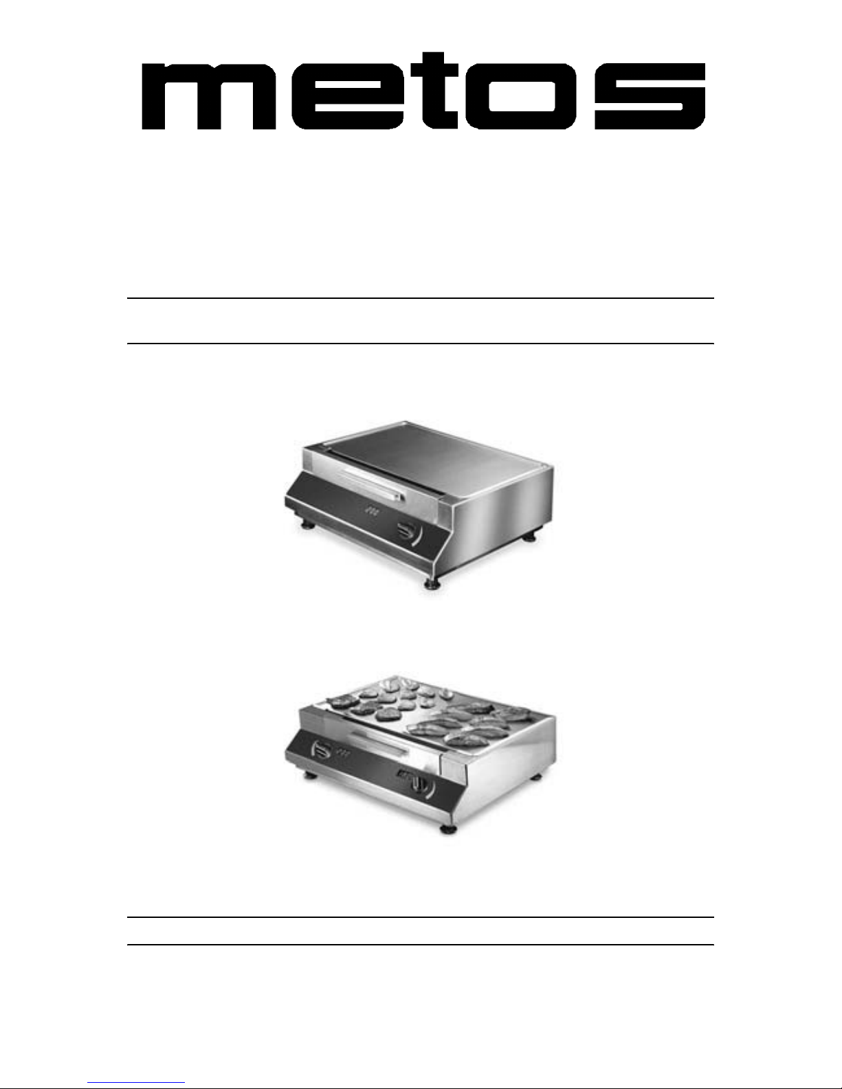
INDUCTION GRIDDLES
GRIDDLE-LINE
TYPE: 3500, 5000, 7000, 10000
Installation and Operation Manual
S/N: Rev.: 2.0
Page 2

Page 3

19.9.2006 Rev. 2.0
Dear C us tom e r ,
Congratulatio ns on deciding to choose a Metos appliance for your kitchen act ivities. You
made an excellent choice. We will do our best to make you a satisfied Metos customer
like thousands of customers we have around the world.
Please read this manual carefully. You will learn correct, safe and efficien t working methods in order to get the best possibl e benefit from the applia nce. Th e instr uctions and hints
in this manual will give you a quick and easy start, and you will soon note how nice it is
to use the Metos equipm ent.
All rights are reserved for technical changes.
You will find the main te chnical da ta on the rating plate fixed to the equipment . When you
need service or technical help, please let us know the serial number shown on the rating
plate. This will make it easier to provide you with corr ect service.
For your convenienc e, spa ce is provide d below f or you to r ecord you r lo cal Me tos s ervic e
contact informati on.
METOS TEAM
Metos service phone number:...............................................................................................
Contact person:....................................................................................................................
Page 4

19.9.2006 Rev. 2.0
Page 5

19.9.2006 Rev.
1. General .......................................................................................................... 1
1.1 Symb o l s us e d i n th e manual ...... .............. ...................................................................... 1
1.2 Symb o l s us e d o n the ap p liance .............. ........................................................................ 1
1.3 Check i n g t h e relation sh i p o f t h e ap p l iance and th e m a n u a l ...................... .................... 1
2. Safety .............................................................................................................. 2
2.1 Safe use of the appliance ............................................................................................... 2
2.1.1 Changing the settings and adjustments .................................................................. 3
2.2 Safe t y instructi o n s in case of a m alfunctio n ......................................................... ......... 3
2.3 Disposal of the appliance ............................................................................................... 3
2.4 Other prohibitions ......................................... .... ...... ... .. .... ...... .... ...... .... ...... .... ...... .... ...... 3
3. Functional description .................................................................................. 4
3.1 Construction .................................................................................................................. 4
4. Operation instructions ................................................................................. 5
4.1 Before using the ap p l iance ................................................................................... ......... 5
4.1.1 Operating test ......................................................................................................... 5
4.2 Operation procedures ..................................................................................................... 5
4.3 After use ................................................................................................................... ..... 6
4.3.1 Cleaning ................................................................................................................ 6
4.3.2 Peri o d i c service .. ............................................................... ..................................... 7
4.3.3 Out of operation .................................................................................................... 7
5. Installation ..................................................................................................... 8
5.1 Preparing the installation ............................................................................................... 8
5.2 Installatio n ........................ .............. .................... ............. .................... .............. ............ 8
5.3 Positioning the appliance ............................................................................................... 9
5.4 Electrical connections .................................................................................................... 9
5.4.1 Single phase supply ............................................................................................... 9
5.4.2 Three phase supply ............................................................. .......... .......... .......... ... 10
5.5 Measures after the installation ..................................................................................... 10
6. Technical specifications .............................................................................. 11
Page 6

19.9.2006 Rev.
Page 7
19.9.2006 Rev. 2.0
General
1
1. General
Carefully read the instructions in this manual as they contain important information regarding proper, efficient and safe installa tion, use and mainten anc e of the appliance.
Keep this manual in a safe place for eventual use by other operators of the appliance.
The installation of this appliance must be carried out in accordance with the manufacturer’s instructions and following local regulations. The connection of the appliance to the
electric and water supply must be carried out by qualified persons only.
Persons using this appliance should be spe cifically traine d in its operation.
Switch off the appliance in the case of failure or malfunction. The periodical function
checks requested in the manua l must be carried out a ccording to the instructions . Have the
appliance serviced by a technically qualified person authorized by the manufacturer and
using original spar e part s.
Not complying with the above may put the safety of the appliance in danger.
1.1 Symbols used in the manual
This symbol in forms about a sit uation whe re a saf ety ri sk m ight be at h and. Give n i nstructions are mandatory in order to prevent injury.
This symbol informs about th e rig ht way to per form in orde r to preve nt bad resul ts, a ppliance damage or hazardous situa tions.
This symbol informs about recom me ndations and hints that help to get the best performance out of the appliance.
1.2 Sy mbols used on th e applia nc e
This symbol on a part informs about electrical terminals behind the part. The removal of
the part must be carried out by qual ified persons only.
1.3 Checking the relationship of the applian ce and the ma nual
The rating plate of the appliance indicates the serial number of the appliance. If the manuals are missing, it is possible to order new ones from the manufacturer or the local representative. When ordering new manuals it is essential to quote the serial number shown
on the rating plate.
Page 8

19.9.2006 Rev. 2.0
Safety
2
2. Safety
2.1 Safe use of the appliance
The table-to p Griddle -Li ne indu ction g riddl es a re es pecia lly s uit able as fryi ng un its i n th e
kitchen for the preparati on of meals. They can be use d for frying and keep ing food warm.
Information signs mounted directly on th e griddle must be observed a t all times and kept
in a fully legible condition.
Danger for persons, for the environment and for the griddle can result from non-observance of the safety information. Certain risks may be associated with non-observance of
precautions, including:
• Danger to persons th rough electrical causes.
• Danger to persons through an overheated heating surface.
• Danger to persons through overheated oil or greas e.
• Danger to persons through a hot case.
The safety information contained in these instruction s fo r use, the existing national regulation for the prevention of acci dents as well as any internal worki ng, operatin g and safety
regulation stipulated by the operator must be obse rved.
Any risks from electric power must be eliminated. The induction unit shall only be used
if the installation of the electricity is fitted by an approved installation contractor in accordance with specific national and local regulations.
• The induction Griddle-Line unit must only be used for frying or keeping warm of
food.
• Never heat-up frying devices as e.g. pans on the griddle plate as this could lead to
thermal damage or destruction.
• Do not put any piece of paper, cardboard, cloth, etc. on the frying area, as this
might initiate a fire.
• Do not place cr edit c ards , phone c ards, cass ette t apes, o r othe r objec ts th at are sensitive to magne tism on the heating surface.
• As metallic objects are heated up very quickly when placed on the frying area, do
not place any ot her objec ts (c lo sed can s, a lumin ium foi l, c utl ery , jewell ery , watc hes etc.) on the induction griddle.
• Persons with a p acemaker s hould a sk the ir doct or whethe r they a re safe ne ar an i nduction griddle or not.
• The induction griddle has an internal air-cooling system. Do not obstruct air inletand air outlet-slots with objects (cloth) as this would cause an overheating and the
griddle would switch off.
Page 9

19.9.2006 Rev. 2.0
Safety
3
• Avoid liquid e nt ering in to t he grid dle . Do not let wat er or foo d ove rflo w the fryi ng
area. Do not clean the griddle with a jet of water.
• If the frying area is cracked or broken, the induction griddle must be switched off
and disconnected from the electric connection. Don't touch any parts inside the
griddle.
2.1.1 Changing the settings and adjustments
Reconstruction of the griddle or changes to the griddle are not allo wed. Contact the ma nufacturer if you intend to make any changes to the griddle. To guarantee the safety, just
use genuine spare parts and accessor ies authorized by the manufacturer. The us e of other
components voids all warranties.
2.2 Safety instructions in case of a malfunction
Do not open the induction gr iddle - dangerous electric voltage inside!
If the frying are a is cr acked or b roke n, the induc tion gr iddl e must b e swit ched off and disconnected from the elec tric suppl y. The griddle may onl y be opened by autho rized servic e
personnel. Do not touch any parts inside the griddle.
2.3 Disposal of the appliance
When the lif e cy cle of th e in du cti on g ridd le end s, mak e s ure th at it wil l be saf ely d ispo se d
of.
Avoid abuse: The gri ddle may not be use d by any person not ha ving the appro priate qualifications. Avoid that the griddle, provided for disposal, can be brought back into operation. The griddle is built up with common electrical, electromechanical and electronic
parts. No b atteries are used.
The operator is responsible for a proper and safe disposal of the induction griddle.
2.4 Other proh ibitions
The operating reli abili ty o f the griddle s ca n only be gu ara nteed wi th pr oper use. The li mit
values may be exceeded on no account.
Page 10

19.9.2006 Rev. 2.0
Functional description
4
3. Functional description
3.1 Construction
The Griddle-Line induction g riddles come in two different sizes, eac h of them in two different power ratings.
Built in a robust case complet ely in stain less steel, the Griddle-Li ne units are compact and
powerful with a revolutionary „RTCS"-technology. The complete case is made of CrNisteel with a deep-drawn griddle plate set -in above. Rounds and a smooth surfac e enable a
rational and optima l cleaning. The te mperature can be chosen via a steples s regulator . The
set and actual fryin g surface temperatures are vis ualized on the LCD displ ay.
• Real-time Temperature Control System allows a temperature regulated frying
process with contactles s temperature measurement and regulation in real-time .
• A special developed induction griddle plate with a HPCR-INOX surface coating.
• The temperature of the whole griddle surface is measured, regulated and checked.
• Instantaneous control of the frying te mperature.
• State-of-the-art SMD-technol ogy, regulated via micr oprocessor.
• A maximum of safety thanks to mul tiple functions of prot ection and checking.
• Electronic checking of the energy suppl y.
• Temperature regul ation between 20° and 250°C.
• Short heat-up time from 20°-200°C in 4 ½ minutes.
• Exchangeable grease filter.
• Europatent EP 0858722.
• Fulfils the latest directions: VDE EN 60335-1/-2/36, CE-conforming UL 197;
CAN/CSA/C 22.2 No. 109, NSF 4-1996.
Page 11

19.9.2006 Rev. 2.0
Operation instructions
5
4. Operation instructions
4.1 Before using the appliance
4.1.1 Operating test
The frying area is warmed up to the s et-i n temper ature . To avoid i nju ries ( burni ng) do not
touch either griddle plate or case.
Turn the temperature power swi tch from positi on 0 to a required position . We recommend
a temperature of 200°C. During the turning of the switch and for two seconds afterwar ds,
the LCD display shows the set temperature. After the two second period, the display
shows again the act u al temperature of the griddle plate.
Turn the power switch in „OFF" position, the LCD display will blank out.
If the display does not function, check the following:
• Is the griddle connected to the main s supply?
• Is the tempera ture knob in „ON" position?
If in spite of all positive controls and tests the grid dle doesn't work, refer to the Fault Fi nding Section.
4.2 Operation procedures
The Griddle-Line uni t is immediate ly ready for use. By choosing the re quired tem perature
and, while the te mperature is s hown on the LCD d isplay, energy i s transf erred t o th e griddle plate. The temperature is ch osen by turning the po w er switch.
We recommend to use frying temperatures between 170° and 200°C.
Only a little oil or gre ase is ne eded o n the HPCR-INOX griddl e surfac e. For fry ing breaded meat, use a little bit more oil or grease. When heating up oil, monitor the frying area
regularly in order to avoid overheating or burning.
Turn the pieces on the griddl e plate with the spatula which is deliver ed with the unit. The
use of sharp knifes or forks can damage the griddle s urface!
The griddle will recognize and react to even smallest drops in the surface temperature
when adding cold foo d on the gri ddl e plat e. The gri ddle wil l re act immedi atel y and adjust
the temperature back on the right level. Because of this, there is no need to pre-heat the
griddle to a higher temperature before starting the process.
After switching th e power switch „OFF", the frying process will be stopped.
Page 12
19.9.2006 Rev. 2.0
Operation instructions
6
4.3 After use
4.3.1 Cleaning
Depending on the degre e of soil ing, t he frying a rea s hall be cle aned r epe atedl y but a t l east
once a day.
• To clean the fryin g area from soili ng, use only pure water. You can add ph-neu tral
detergents produced on a base of non-ionic tens ides.
• Lime residue on th e frying area c an be removed wit h a commercia l lim e det ergent.
• For the cleaning of the frying area, please use the stainless steel sponge and the
special griddle spatula which are delivered together with the Griddle-Line unit.
• For any cleaning between the frying processes, we recommend the use of ice
cubes. The soi ling will dis solve qui ckly and can ea sily be removed wi th the griddl e
spatula.
• For a daily cleaning, please cool down the frying area to about 50°C.
• Avoid strong detergents and dissolvers as well as alkaline detergents. Depending
on concentration, reaction time and temperature, they could lead to a damage of
the HPCR-INOX heating surface. Do not use scratching devices as steel wool or
scratching sponges as they could also damage the heating surface.
• Mechanical abuse such as strikes can lead to a shortened life cycle of the heating
surface.
• Do not clean the induction unit by running water, a jet of water or steam.
• The cleaning of the frying area can produce hot steams - danger of burning!
Make sure that no liquid can enter into the induction unit.
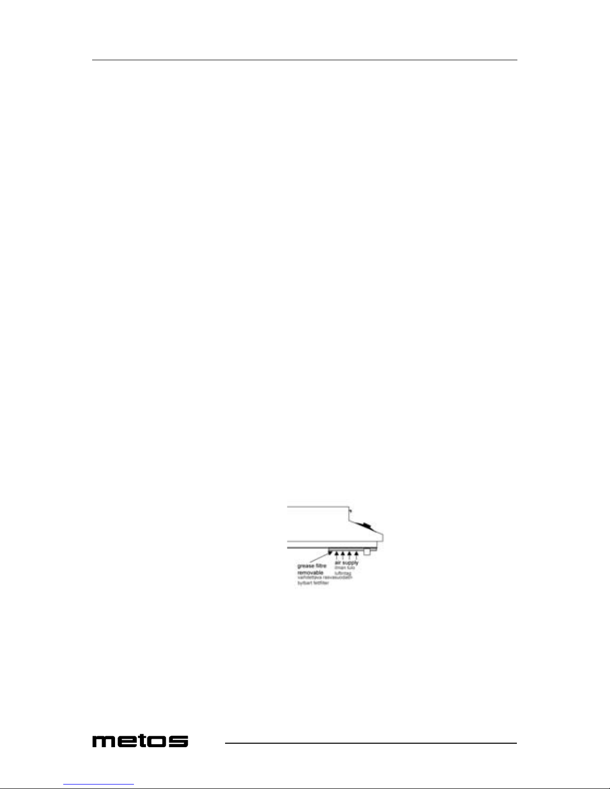
The unit is equipped with a removable grease filter under the front side of the unit. This
filter needs to be clea ned peri odica lly depe nding on t he u sage and t he am bient a ir qual ity .
Before removing the filter, unplug the unit from the mains. The filter must be in place
again before plugging in the unit. The unit mus t never be used without the gr ea se filter in
its place.
Page 13

19.9.2006 Rev. 2.0
Operation instructions
7
4.3.2 Periodic service
A good maintenance of the induction griddl e requires a r egular cleaning , care and servicing. The opera tor has to e nsure th at a ll c omponen ts rele va nt for safe ty are i n perf ect working order at al l t imes. The gr iddl e has t o be exam ined at least onc e a ye ar by a n au thor ized
technician.
Do not open the griddle, dangerous electric volt age inside.
The griddle may only be opened by au thorized personnel .
4.3.3 Out of operation
If the griddle is not in u se, m ake sure that the temper ature knob is in the “OFF” pos ition.
If you don’t use the griddle for a longer pe riod (several d ays ), unplug the unit. Make sure
that no liquid can enter into the griddle and do not clean the griddle wit h a jet of water.
Page 14

19.9.2006 Rev. 2.0
Installation
8
5. Installation
5.1 Preparing the installation
Please observe the following rules:
• Check and ensure that the supply voltage matches the voltage given on the rating
plate.
• The electrical connections must satisfy local house installation regulations. The
valid, nati onal and local electrical regulati ons must be observed.
• This indu ction applia nce i s equ ipped wi th a cabl e whic h can b e conne cted wit h the
necessa ry plu g to the soc ket. Th e sock et must be easi ly acce ssible to disc onnect
the unit from the net.
• When faulty-current circuit breakers are used, they must be rated for a breaking
current of 30mA or more.
• This induction unit is equipped with an air cooling system. Make sure that the air
supply and air exhaust are not blocked (wall, fabric etc.).
• This induction unit i s equipped with a n additional grease filter. Make sure that the
induction unit does not take in hot ambient air (concerns units standing side by
side, or one behind the other, or standing near a frying pan or an oven).
• The induction unit must not be placed near or on a hot surface.
• The air intake te mper ature must be under 40°C.
• The operating staff has to make sure that installation is done by qualified personnel.
5.2 Installation
The griddle is e quipped with a cable . It has to be connected to a wall socket. If no plug is
installed at the cable, do the connection according to the information in “Electrical connections”. The installation for the electricity must be carried out by approved installation
contractors in accordance with specific national and local regulations. The installation
contractors are responsible for the correct layout and installation in conformity with all
safety regulations. The warning signs and rating plates put up to the appliances must
strictly be followed. Check and ensure, that the mains voltage matches with the voltage
given on the rating plate.
The griddle must always be installed on a clean and even surface (table, base, etc.) at its
designated site. The griddle stands on non-slip rubber feet and is not permanently installed. It must be installed in such a way that it cannot fall down or move in a uneven
position. The conditions for the “positioning the appliance” must be guaranteed.
Page 15
19.9.2006 Rev. 2.0
Installation
9
5.3 Positioning the appliance
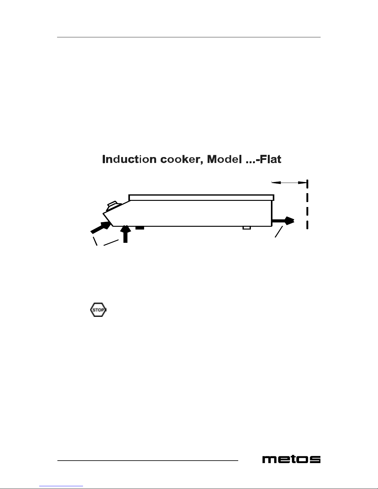
The griddle has to be set up on an even surface. The air inlet and air outlet must not be
obstructed, the ar ea must be able to car ry a loading of 80 kg. The griddl e does not need to
be fixed on the table. The temperature knob to operate the griddle must be ea sily accessible.
Installation am bience:
• Max. ambient temper ature: Storage > -20 - +70°C, function> + 5 - +40°C
• Max. relative humidity of air: Storage > 10% - 90%, funct ion> 30% - 90%
5.4 Electrical connections
The electrical conne ction must be done by an expert.
5.4.1 Single phase supply
Induction appliance: Type Griddle-Line 3500. The griddle is equipped with a cable conforming to the national regulations.
Make sure that the plug is connected the right way:
• Phase: brown (Colour of the conductor)
• Neutral: blue (Colour of the conductor)
• Protective ground: green-yellow (Colour of the conductor)
d: minimal distance to the wall = 4 c
air inlet
side view
air outlet
d
Induktioliesi/ induktionsspis
/sivulta/ från sidan
ilmanotto/ luftintag
ilmanlähtö/ luftutlopp
m
minimietäisyys seinään
minimiavstånd till väggen
Page 16

19.9.2006 Rev. 2.0
Installation
10
If the voltage is wrong, the griddle can be damaged.
• Voltage: max + 6 / -10 % from the connection voltage
• Frequency: 50 Hz / 60 Hz
• Preliminary f use: 16A- Griddle-Line 5000 and 7000; 16A - Griddle-Line 10000.
5.4.2 Three phase supply
Induction appliance: Model Griddle-Line 5000, 7000, 10000. The griddles are equipped
with a cable conforming to the national regulations.
Make sure that the plug is connected the right way:
• Phase 1,2,3: black / brown/blue (Colour of the conductor) or other colours, except
of grey, green or white
• Protective ground: green / yellow (Colour of the conductor)
If the voltage is wrong, the griddle can be damaged.
• Voltage: max + 6 / -10 % from the connection voltage
• Frequency: 50 / 60 Hz
• Preliminary f use: 10A - Griddle-Line 5000 and 7000
• Preliminary f use: 16A - Griddle-Line 10000
5.5 Measures after the installation
Turn the temperature knob in the OFF-position before connecting the griddle to the voltage supply. Befo re car ryin g out func ti on tes ts, th e op erator has t o kno w how to ha ndle the
induction Griddle - Line unit.
Place the i nduction Griddle -Line unit at its final place and connect it to the mains supply.
Make sure that the unit is standing well and cannot move.
Remove all obje cts from the griddle pla te. Veri fy if this a rea is nei ther crac ked nor broken .
If the griddle plate is cracked or broken, immediately switch the griddle off, disconnect
the griddle from the outlet and contact your lo cal service.
Page 17

19.9.2006 Rev. 2.0
Technical specifications
11
6. Technical specifications
Installation drawing
Page 18
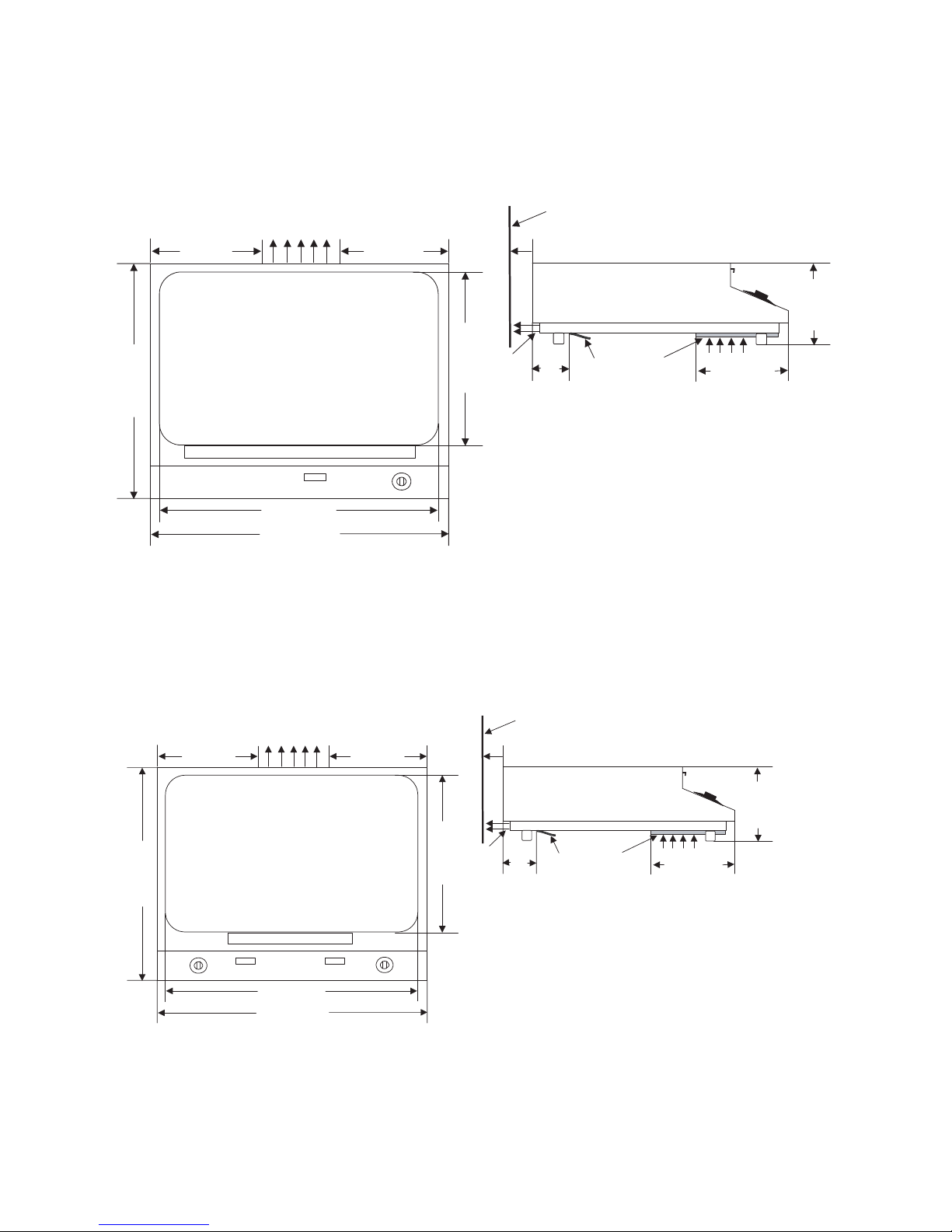
Installation drawing
I
521mm (20.5")
)"3,71(mm044
195mm (7.7")
175mm (6.9")
air exhaust
wall
d d: min. distance to wall = 40mm (1.6")
air
exhaust
70mm (2.7")
air supply
grease filtre
removable
220mm (8.7")
)"8.7(mm891
net cable
griddle top
)"8.11(mm003
475mm (18.7")
grease drawer
I
646mm (25.4")
"2.42(mm566)
285mm (11.2")
261mm (10.3")
air exhaust
wall
d d: min. distance to wall = 40m m (1.6")
air
exhaust
70mm (2.7")
air supply
grease filter
removable
220mm (8.7")
"8.7(mm891 )
net cabel
griddle top
"7.02(mm525 )
600mm (23.6")
grease drawer
Griddle-Line 3500, 5000
Griddle-Line 7000, 10000
Page 19
19.9.2006 Rev. 2.0
Technical specifications
13
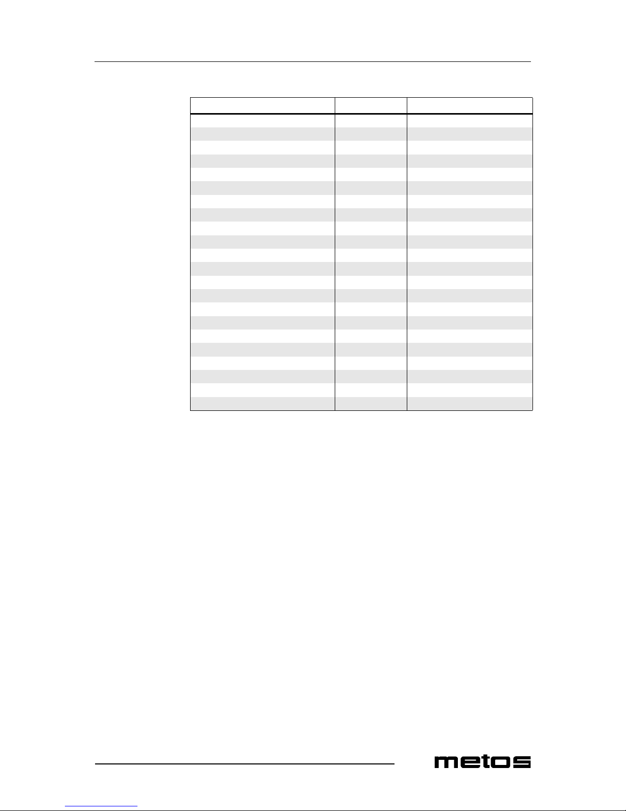
GRIDDLE-LINE
Item Type Specification
Lamp 24V DC/max. 40mA (red)
Key pad and LED dis play
Dimensions WxDxH 3500, 5000 521x440x19 8 mm
Dimensio ns WxDxH 7000, 10000 646x665x19 8 mm
Voltage 3500 230V
Voltage 5000,7000,10000 400V
Current 3500 16 A
Current 5000 10 A
Current 7000 10 A
Current 10000 16 A
Power 3500 3,5 kW
Power 5000 5,0 kW
Power 7000 7,0 kW
Power 10000 10,0 kW
Weight 3500 22 kg
Weight 5000 22 kg
Weight 7000 45 kg
Weight 10000 45 kg
Operation condition s:
Max. tolerance of the nominal supply +6/-10%
Supply frequency 50/60 Hz
Protection class IP X0
Page 20
 Loading...