


OPERATING MANUAL
®
METO-FER
MINI LINEAR UNIT TYPE ML 33-…-0
AUTOMATION AG
ML 33-…-A
ML 33-…-B
ML 33-…-C
SERIES FROM 5-25
1. PRODUCT DESCRIPTION
1.1 Introduction
1.1.1. Utilization
The mini linear unit ML 33-... (Type O,A,B,C) is able to execute linear
movements in any position. This linear movement can be adjusted in its working area
(stroke).
1.1.2. Safety Precautions
Before starting to operate the mini linear unit ML 33-... (Type O,A,B,C), it is
necessary to check that no body parts are within the working range of the element.
The maximum supply pressure of 8 bar must not be surpassed.
1.1.3. Danger Area
Any body parts are to be kept out of the working area (stroke area) of the unit in
order to avoid mangling.
1.2 Technical Data
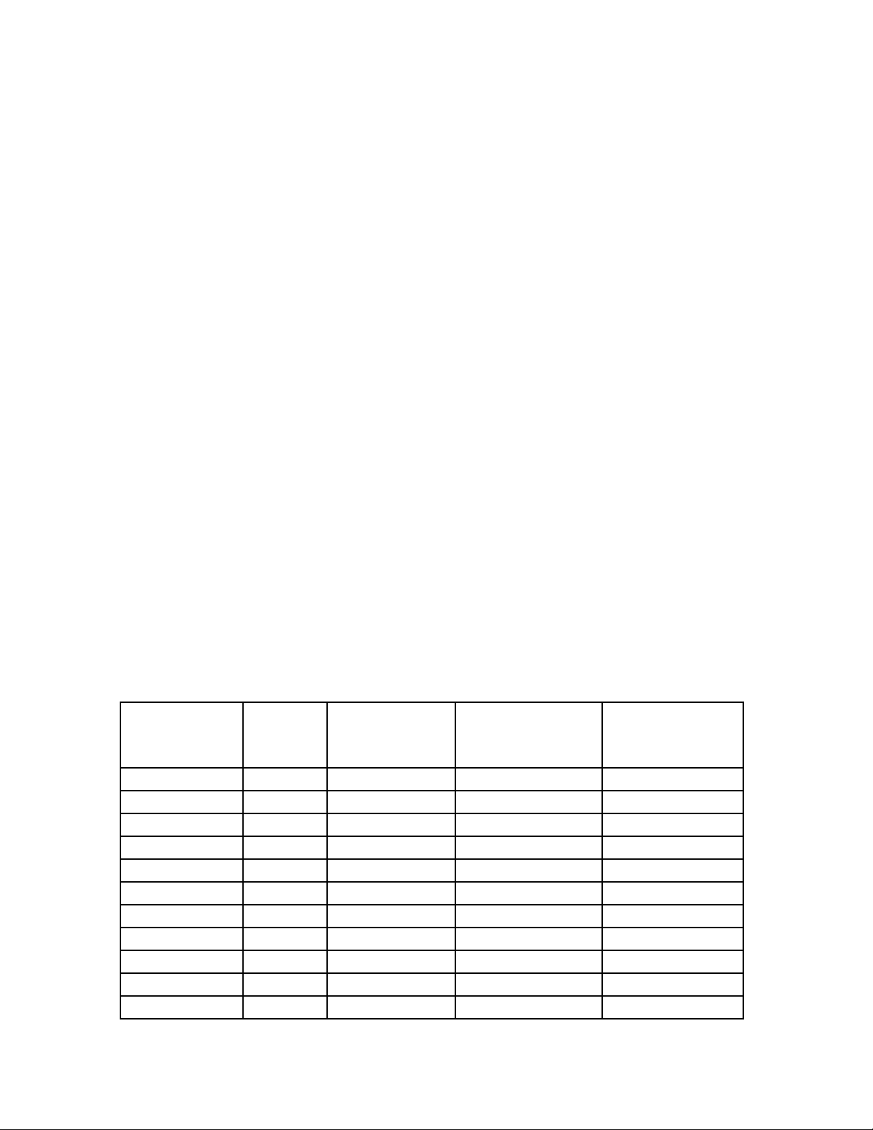
1.2.1 Weights and Measurements
See also Sheet 5
Adjustment A (See Weight
Type Stroke Range
Sheet 5) Lb.(kg)
Between
ML 33-025 0-25mm 0-27mm 157mm 8.9 (4.05)
ML 33-050 0-52mm 0-52mm 182mm 9.4 (4.25)
ML 33-075 0-75mm 8-77mm 207mm 9.9 (4.50)
ML 33-100 0-100mm 33-102mm 232mm 10.4 (4.70)
ML 33-125 0-125mm 58-127mm 257mm 10.8 (4.90)
ML 33-150 0-150mm 83-152mm 282mm 11.45 (5.15)
ML 33-175 0-175mm 108-177mm 307mm 11.8 (5.35)
ML 33-200 0-200mm 133-202mm 332mm 12.2 (5.55)
ML 33-250 0-250mm 183-252mm 382mm 13.2 (6.00)
ML 33-300 0-300mm 233-302mm 432mm 14.1 (6.40)
ML 33-350 0-350mm 283-352mm 482mm 15.1 (6.85)
1

ML 33-400 0-400mm 333-402mm 532mm 16.0 (7.24)
2
OPERATING MANUAL (ML 33)
)
(Nm)
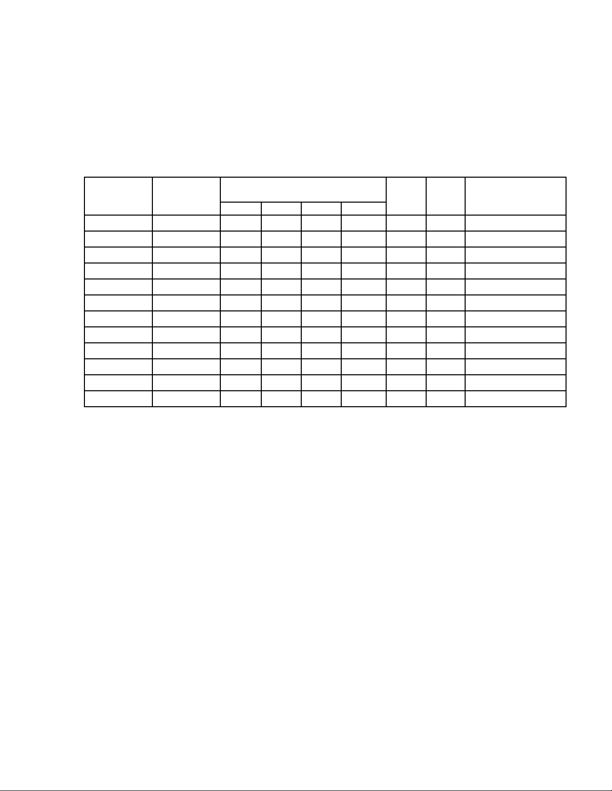
1.2.2. Performance Characteristics
Piston
force
Type at 5 bar F1 F2 F3 F4(Nm
Lifting force static/dynamic Ma Mb Air
Consumption
per stroke
ML 33-025 300N 823N 861N 982N 1013N 38.0 64.0 0.23 NL
ML 33-050 300N 499N 522N 982N 1013N 32.5 54.5 0.45 NL
ML 33-075 300N 340N 355N 865N 892N 28.5 47.5 0.67 NL
ML 33-100 300N 281N 295N 865N 892N 28.5 47.5 0.90 NL
ML 33-125 300N 203N 213N 728N 750N 24.0 40.0 1.12 NL
ML 33-150 300N 178N 186N 728N 750N 24.0 40.0 1.35 NL
ML 33-175 300N 148N 155N 680N 702N 22.5 37.5 1.57 NL
ML 33-200 300N 125N 131N 637N 657N 20.5 34.5 1.79 NL
ML 33-250 300N 100N 105N 610N 628N 20.0 33.5 2.24 NL
ML 33-300 300N 79N 83N 561N 578N 18.5 30.5 2.69 NL
ML 33-350 300N 66N 69N 532N 549N 17.5 29.5 3.14 NL
ML 33-400 300N 57N 59N 512N 528N 16.5 28.0 3.59 NL
NL: Normal Liter
Repetition accuracy +/-0.0004" (0.01mm)
1.2.3 Operating Source
40mm filtered, unoiled or oiled air (dew point 6oC)
Operating pressure P
1.2.4 Connections
Air connections R 1/8 (see sheet 6)
1.2.5 Environment
Temperature 50
Relative humidity 95% (without condensation of water)
Purity of the environment air regular working place atmosphere
3 bar
min
P
o
F to122oF (+ 10oC to + 50oC)
3
max
8 bar

OPERATING MANUAL (ML 33)
1.3 Features
1.3.1 Standard Features (included in delivery)
The unit delivered will have two patented end screws type AS 12/60 with fine
thread. These end screws adjust the stroke within its working area. According to
the type, the units are equipped with the following cushions:
Mini Linear Unit Cushions Type
ML 33-…O No cushions ---ML 33-…A Elastomer cushions PM25MF,
ML 33-...B Oil cushions OB 15/10K
ML 33-...C Oil cushions with compensation
reservoir
KB08/M14X1
OB 15/10K with
KOB 50
1.3.2 Special Equipment
The end screws can be fitted with the patented sensing elements (see Meto-Fer
Electronic catalog, pages 22 and 23) in order to check the end position.
2. SAFETY REGULATIONS
2.1 In general
See chapters 1.1.1
1.1.2
1.1.3
2.2 Specifically
Do not make any changes or modifications to the unit (voids warranty).
3. CONSTRUCTION AND FUNCTION
The stroke adjustment can be made infinitely variable with the end screw AS
12/60 (Pos.101) in order to check the occurred movement, the end screws can be
fitted with our sensing elements (see Meto-Fer
®
Electronics catalog).
®
4

5

OPERATING MANUAL (ML 33)
4. INITIAL OPERATION
4.1 Compressed Air
Remove the safety caps from the air connections. In order to regulate the velocity
of the movement, we recommend our flow control valves DV-R1/8" (see sheet
5.021). Unused air connections must be covered with the R1/8 caps.
4.2 Stroke Adjustment
- loosen security nut on the end screw
- adjust the required stroke with the end screw (Pos.101)
- tighten security nut on the end screw
4.3 Cushion Adjustment
The basic adjustment of the cushions has to be optimized by the user upon
his special requirements.
The position of the cushions can be seen on the construction drawing.
The brake resistance can be changed by adjusting the length of the brake path.
When using oil and elastomer cushions, it must be checked that the end stop is
not made by the cushions. The cushions should show a remainder stroke of
0.039” (1mm).
5. MAINTENANCE
5.1 Introduction
The mini linear unit does not require any special maintenance procedure. Never
use any type of solvents in order to clean the unit.
5.2 Air Supply
The mini linear unit is equipped with oil-free seals and can be operated with dry
and non-oiled compressed air. If oiled compressed air is used, we recommend:
- Airpress compound SAE 5 (Klueber Order No. 063027)
6

7

OPERATING MANUAL (ML 33)
6. REPAIR
6.1 Introduction
If the unit no longer meets the requirements (leakage, wear, etc.) the
defective parts must be replaced.
6.2 Safety Precautions
Before dismounting the unit, it is necessary to check that the compressed air
supply is turned off. It is best to disconnect the compressed air supply from the
unit.
When repair work is done, only the original spare parts and lubrication must be
used.
6.3 Replacing the Seals
- Remove the end plate (Pos.2) by loosening the set screw (Pos.202).
- Remove the cylinder tube (Pos.7) with the special wrench. Don’t loosen
the brass cover.
- Loosen and extract the piston rod (Pos.8).
- Extract the housing (Pos.1).
- Replace the seals.
- Lubricate the cylinder bore and piston rod with grease (see Chapter 7.2).
- The parts are then assembled in reverse order as described above.
6.4 Replacing the linear ball bushings
- Remove the end plate (Pos.2), the cylinder tube and extract the piston rod
as described in chapter 6.3.
- Extract the housing.
8

- Press out the linear ball bushings (Pos.208).
9

OPERATING MANUAL (ML 33)
- Press in the new linear ball bushings. Make sure that the piston seal rings
lie on the outside of the housing.
- The parts are then assembled in reverse order as described above.
7. SPARE PARTS LIST
7.1 Spare Parts
When ordering spare parts, the type and serial number of the unit must be
supplied.
Position Part Number Description Amount
*206 025.150.0810 Piston Seal 1 piece
*207 025.140.0057 Rod Seal 1 piece
208 045.100.0007 Linear Ball Bushings 4 pieces
*214 025.100.0695 O-Ring 1 piece
Seal Kit Order No. 460.100.0257 all items marked with (*)
Repair Kit Order No. 460.110.0137 kit includes Pos.208
7.2 Lubrication
Grease for seals Staburag NBU 4 Atemp.
Grease for linear ball bushings Staburag NBU 4 Atemp.
(Klueber Order No.005 040)
(Klueber Order No.005 040)
10

11
 Loading...