

Page 1

OPERATING MANUAL
®
METO-FER
MINI LINEAR UNIT ML 26-…-0
AUTOMATION AG
SERIES FROM 4-50
ML 26-…-A
ML 26-…-B
ML 26-…-C
Page 2
1. PRODUCT DESCRIPTION
1.1 Introduction
1.1.1. Utilization
The mini linear unit ML 26-... (Type O,A,B,C) is able to execute linear
movements in any position. This linear movement can be adjusted in its working area
(stroke).
1.1.2. Safety Precautions
Before starting to operate the mini linear unit ML 26-... (Type O,A,B,C), it is
necessary to check that no body parts are within the working range of the element.
The maximum supply pressure of 8 bar must not be surpassed.
1.1.3. Danger Area
Any body parts are to be kept out of the working area (stroke area) of the unit in
order to avoid mangling.
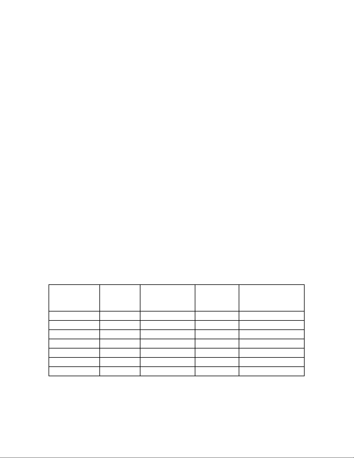
1.2 Technical Data
1.2.1 Weights and Measurements
See also Sheet 5
Type Stroke
Adjustment
Range Between
A (See
Sheet 5)
Weight
Lb. (kg)
ML 26-025 0-25mm 0-25mm 147mm 3.7 (1.7)
ML 26-050 0-50mm 0-50mm 172mm 4.0 (1.8)
ML 26-075 0-75mm 24-75mm 197mm 4.2 (1.9)
ML 26-100 1-100mm 49-100mm 222mm 4.4 (2.0)
ML 26-125 0-125mm 74-125mm 247mm 4.6 (2.1)
ML 26-150 0-150mm 99-150mm 272mm 4.9 (2.2)
ML 26-200 0-200mm 149-200mm 322mm 5.5 (2.5)
1
Page 3
OPERATING MANUAL (ML 26)
(Nm)
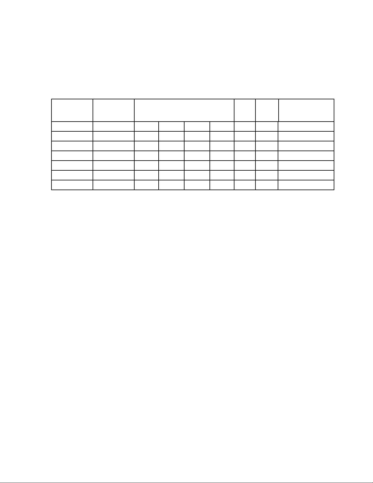
1.2.2. Performance Characteristics
Type
Piston
force
at 5 bar
Lifting force static/dynamic
F1 F2 F3 F4
Ma
(Nm
)
Mb
Air
Consumption
per stroke
ML 26-025 154N 721N 754N 746N 770N 28.0 40.5 0.14NL
ML 26-050 154N 404N 422N 777N 794N 22.5 33.5 0.27NL
ML 26-075 154N 207N 311N 712N 734N 20.0 29.5 0.41NL
ML 26-100 154N 216N 226N 617N 636N 18.0 26.0 0.54NL
ML 26-125 154N 182N 169N 516N 583N 16.0 23.5 0.68NL
ML 26-150 154N 136N 143N 518N 548N 15.5 22.5 0.81NL
ML 26-200 154N 99N 104N 494N 509N 14.5 21.5 1.08NL
NL: Normal Liter
Repetition accuracy +/-0.0004" (0.01mm)
1.2.3 Operating Source
40mm filtered, unoiled or oiled air (dew point 6oC)
Operating pressure P
P
min
max
3 bar
8 bar
1.2.4 Connections
Air connections R 1/8 (see sheet 6)
1.2.5 Environment
Temperature 50
Relative humidity 95% (without condensation of water)
Purity of the environment air regular working place atmosphere
o
F to 122oF (+ 10oC to + 50oC)
2
Page 4

OPERATING MANUAL (ML 26)
1.3 Features
1.3.1 Standard Features (included in delivery)
The unit delivered will have two patented end screws type AS 10/50 with fine
thread. These end screws adjust the stroke within its working area. According to
the type, the units are equipped with the following cushions:
Mini Linear Unit Cushions Type
ML 26-…-O No cushions ---ML 26-…-A Elastomer cushions KB 08/M14X1
ML 26-…-B Oil cushions OB 15/10K
ML 25-…-C Oil cushions with
OB 15/10K with KOB 50
compensation reservoir
1.3.2 Special Equipment
The end screws can be fitted with the patented sensing elements (see Meto-Fer
Electronic catalog, pages 22 and 23) in order to check the end position.
2. SAFETY REGULATIONS
2.1 In general
See chapters 1.1.1
1.1.2
1.1.3
2.2 Specifically
Do not make any changes or modifications to the unit (voids warranty).
3. CONSTRUCTION AND FUNCTION
®
3
Page 5

The stroke adjustment can be made infinitely variable with the end screws AS
10/50 (Pos.101) in order to check the occurred movement, the end screws can be
fitted with our sensing elements (see Meto-Fer® Electronics catalog).
4
Page 6

OPERATING MANUAL (ML 26)
4. INITIAL OPERATION
4.1 Compressed Air
Remove the safety caps from the air connections. In order to regulate the velocity
of the movement, we recommend our flow controls DV-R1/8" (see sheet 5.021).
Unused air connections must be covered with the R1/8 caps.
4.2 Stroke Adjustment
- loosen security nut on the end screw
- adjust the required stroke with the end screw (Pos.101)
- tighten security nut on the end screw
4.3 Cushion Adjustment
The basic adjustment of the cushions has to be optimized by the user upon
his special requirements.
The position of the cushions can be seen on the construction drawing.
The brake resistance can be changed by adjusting the length of the brake path.
When using oil and elastomer cushions, it must be checked that the end stop is
not made by the cushions. The cushions should show a remainder stroke of
0.0394” (1mm).
5. MAINTENANCE
5.1 Introduction
The mini linear unit does not require any special maintenance procedure Never
use any type of solvents in order to clean the unit.
5.2 Air Supply
The mini linear unit is equipped with oil-free seals and can be operated with dry
and non-oiled compressed air. If oiled compressed air is used, we recommend:
- Airpress compound SAE 5 (Klueber Order No. 063027)
5
Page 7

6
Page 8

OPERATING MANUAL (ML 26)
6. REPAIR
6.1 Introduction
If the unit no longer meets the requirements (leakage, wear, etc.) the
defective parts must be replaced.
6.2 Safety Precautions
Before dismounting the unit, it is necessary to check that the compressed air
supply is turned off. It is best to disconnect the compressed air supply from the
unit.
When repair work is done, only the original spare parts and lubrication must be
used.
6.3 Replacing the Seals
Remove the end plate (Pos.2) by loosening the set screw (Pos.202).
Remove the cylinder tube (Pos.7) with the special wrench. Don’t loosen the brass
cover.
Loosen and extract the piston rod (Pos.8).
Extract the housing (Pos.1).
Replace the seals.
Lubricate the cylinder bore and piston rod with grease (see Chapter 7.2).
The parts are then assembled in reverse order as described above.
6.4 Replacing the linear ball bushings
Remove the end plate (Pos.2), the cylinder tube and extract the piston rod as
described in chapter 6.3.
Extract the housing (Pos.1).
7
Page 9

OPERATING MANUAL (ML 26)
Press out the linear ball bushings (Pos.208).
Press in the new greased linear ball bushings. Take care that the piston seal rings
lie on the outside of the housing.
The parts are then assembled in reverse order as described above.
7. SPARE PARTS LIST
7.1 Spare Parts
When ordering spare parts, the type and serial number of the unit must be
supplied.
Position Part Number Description Quantity
*206 025.150.0800 Piston Seal 1 piece
*207 025.140.0057 Rod Seal 1 piece
208 045.100.0006 Linear ball bushings 4 pieces
*214 025.100.0585 O-Ring 1 piece
Seal Kit Order No. 460.100.0251 all items marked with (*)
Repair Kit Order No. 460.110.0128 kit includes Pos.208
7.2 Lubrication
Grease for seals Staburag NBU 4 Atemp.
Grease for linear ball bushings Staburag NBU 4 Atemp.
(Klueber Order No. 005 010)
(Klueber Order No. 005 040)
8
Page 10

9
 Loading...