


OPERATING MANUAL
METO-FER® AUTOMATION AG
LINEAR UNIT TYPE LH 100-…
LH 150-…
LH 200-…
LH 300-…
LH 400-…
SERIES FROM 5-32
1. PRODUCT DESCRIPTION
1.1 Introduction
1.1.1. Utilization
The linear unit LH is able to execute linear movements in any position. This linear
movement can be adjusted in its working area (stroke).
1.1.2. Safety Precautions
Before starting to operate the linear unit LH, it is necessary to check that no body
parts are within the working range of the element. In such a case the unit must not
be operated.
The maximum supply pressure of 8 bar must not be surpassed.
1.1.3. Danger Area
Any body parts are to be kept out of the working area (stroke area) of the unit in
order to avoid mangling.
1.2 Technical Data
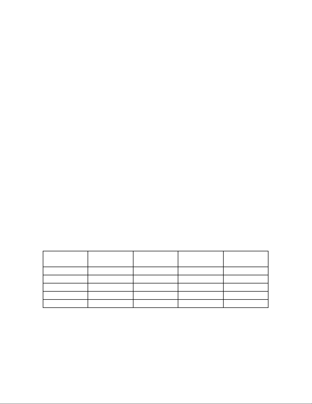
1.2.1 Weights and Measurements
See also Sheet 5
Type Stroke A B Weight
LH 100 0-100mm 352mm 234mm 11.0(5.0)
LH 150 0-150mm 452mm 284mm 12.8(5.8)
LH 200 0-200mm 552mm 334mm 14.6(6.6)
LH 300 0-300mm 752mm 434mm 18.1(8.2)
LH 400 0-400mm 952mm 534mm 21.6(9.8)
Lb.(kg)
1
OPERATING MANUAL (LH)
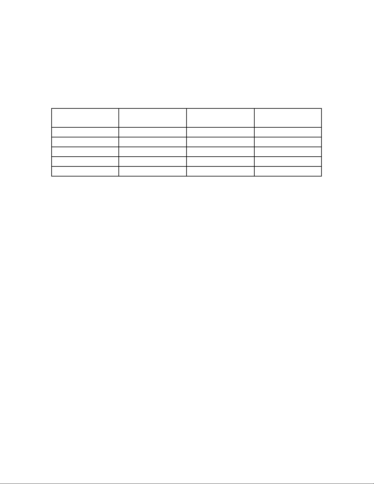
1.2.2. Performance Characteristics
Type
Piston force at 5
bar
Max load
(kg) Air consumption*
LH 100 226 N 28.0 kg. 0.73 NL
LH 150 226 N 16.0 kg 1.09 NL
LH 200 226 N 9.0 kg 1.45 NL
LH 300 226 N 4.5 kg 2.18 NL
LH 400 226 N 3.0 kg 2.90 NL
NL: Normal Liter
*Air consumption for each double stroke at 72.5 PSI (5 Bar)
Repetition accuracy +/-0.0004" (0.01mm)
1.2.3 Operating Source
40mm filtered, unoiled or oiled air (dew point 6oC)
Operating pressure P
P
min
max
3 bar
8 bar
1.2.4 Connections
Air connections R 1/8 (see sheet 6)
1.2.5 Environment
Temperature 50
o
F to 122oF (+ 10oC to + 50oC)
Relative humidity 95% (without condensation of water)
Purity of the environment air regular working place atmosphere
1.3 Features
1.3.1 Standard Features (included in delivery)
2

The unit delivered will have two patented end screws type AS 12/60 with fine
thread. These end screws adjust the stroke within its working area. According to
the type, the units are equipped with the following cushions:
3

OPERATING MANUAL (LH)
1.3.2 Special Equipment
The end screws can be fitted with the patented sensing elements (see Meto-Fer
Electronic catalog, pages 22 and 23) in order to check the end position.
To add one or more intermediate positions, please usethe following parts:
See also Sheet 7
Type A B
Intermediate
position with
SA 01
Intermediate
position with
SA 01 A
LH 100 193 175 ZB 03.040 ZB 03.040 A
LH 150 243 225 ZB 03.035 ZB 03.035 A
LH 200 293 275 ZB 03.045 ZB 03.045 A
LH 300 393 375 ZB 03.050 ZB 03.050 A
LH 400 493 475 ZB 03.055 ZB 03.055 A
2. SAFETY REGULATIONS
2.1 In general
®
See chapters 1.1.1
1.1.2
1.1.3
2.2 Specifically
Do not make any changes or modifications to the unit (voids warranty).
3. CONSTRUCTION AND FUNCTION
The stroke adjustment can be made infinitely variable with the end screws AS
12/60 (Pos.101) in order to check the occurred movement, the end screws can be
fitted with our sensing elements (see Meto-Fer
4
®
Electronics catalog).

OPERATING MANUAL (LH)
4. INITIAL OPERATION
4.1 Compressed Air
Remove the safety caps from the air connections. In order to regulate the velocity
of the movement, we recommend our one-way restrictors DV-R1/8" (see sheet
5.021). Unused air connections must be covered with the R1/8 caps.
4.2 Stroke Adjustment
- Loosen screw (Pos.102 and 110) and plate (Pos.9), move to the needed
position.
- Tighten screw, make sure piston rod and shaft (Pos.6) are parallel.
- Loosen nut on stop screw.
- Adjust the needed stroke on AS 12/60 (Pos.115).
- Tighten security nut on the stop screw.
4.3 Cushion Adjustment
The basic adjustment of the cushions has to be optimized by the user upon
his special requirements.
The position of the cushions can be seen on the construction drawing.
The brake resistance can be changed by adjusting the length of the brake path.
When using oil and elastomer cushions, it must be checked that the end stop is
not made by the cushions. The cushions should show a remainder stroke of
0.039” (1mm).
5. MAINTENANCE
5.1 Introduction
5

The linear unit does not require any special maintenance procedure. Never use
any type of solvents in order to clean the unit.
OPERATING MANUAL (LH)
5.2 Air Supply
The linear unit is equipped with oil-free seals and can be operated with dry
and non-oiled compressed air. If oiled compressed air is used, we recommend:
- Airpress compound SAE 5 (Klueber Order No. 063027)
6. REPAIR
6.1 Introduction
If the unit no longer meets the requirements (leakage, wear, etc.) the
defective parts must be replaced.
6.2 Safety Precautions
Before dismounting the unit, it is necessary to check that the compressed air
supply is interrupted. It is best to disconnect the compressed air supply from the
unit.
When repair work is done, only the original spare parts and lubrication must be
used.
6.3 Replacing the Seals
- Remove the end plate (Pos.9) by loosening the screws (Pos. 102, 110).
- Loosen the set screws (Pos.106) and remove plate (Pos.8).
- Extract the housings (Pos.1).
- Extract the piston rod and guide shaft (Pos. 5 and 6).
- Extract the cylinder pipe (Pos.4).
- Clean the parts.
6

- Replace the seals.
- Check all parts for wear and grease cylinder pipe, guide shaft, piston rod
(see Chapter 7.2).
OPERATING MANUAL (LH)
- The parts are then assembled in reverse order as described above.
6.4 Replacing the linear ball bushings
Disassembly same as Chapter 6.3.
- Extract linear ball bushings.
- When assembling the ball bushings, make sure the seal rings lie on the
outside of the housing.
The parts are then assembled in reverse order as described in Chapter 6.3.
7. SPARE PARTS LIST
7.1 Spare Parts
When ordering spare parts, the type and serial number of the unit must be stated.
Position Part Number Description Quantity
*109 015.130.0100 Clips 2 Pieces
*111 025.100.0680 O-Rings 2 Pieces
*112 025.140.0055 Rod Seals 2 Pieces
*113 025.150.0810 Piston Seals 2 Pieces
114 045.100.0007 Linear Ball Bushings 4 Pieces
*117 025.100.0410 O-Ring 1 Stk.
Seal Kit Order No. 460.100.0056 all items marked with (*)
Repair Kit Order No. 460.110.0246 kit includes Pos.114
7.2 Lubrication
Grease for seals Staburag NBU 4 Atemp.
7

(Klueber Order No. 005 040)
Grease for linear ball bushings Staburag NBU 4 Atemp.
(Klueber Order No. 005 040)
8
 Loading...