


OPERATING MANUAL
®
METO-FER
ELEVATING TABLE TYPE HT 20 A
AUTOMATION AG
HT 20 B
HT 20 C
SERIES FROM 5-52

1. PRODUCT DESCRIPTION
1.1 Introduction
1.1.1. Utilization
The elevating table HT 20 (Type A, B, C) is able to execute linear movements
in any position. This linear movement can be adjusted in its working area
(stroke).
1.1.2. Safety Precautions
Before starting to operate the elevating table (Type A, B, C), it is necessary to
check that no body parts are within the working range of the element.
In such a case the unit must not be operated.
The maximum supply pressure of 8 bar must not be surpassed.
1.1.3. Danger Area
Any body parts are to be kept out of the working area (stroke area) of the unit in
order to avoid mangling.
1.2 Technical Data
1.2.1 Weights and Measurements
See also Sheet 5
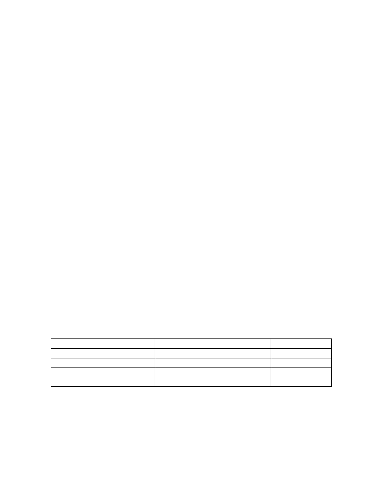
Type Strok
e
(mm)
HT 20
0-20 135 9 45 267N 0.19 NL 10.14(4.6)
A
(mm)B(mm)C(mm)
Piston
force at 5
bar
A,B,C
*Air consumption per each double stroke at 72.5 PSI (5 bar).
Air
consumption*
NL: Normal Liter
Weight
Lb.(kg)
1
OPERATING MANUAL (HT)
1.2.2. Performance Characteristics
Repetition accuracy +/-0.0004" (0.01mm)
1.2.3 Operating Source
40mm filtered, unoiled or oiled air (dew point 6oC)
Operating pressure P
1.2.4 Connections
Air connections M-5 (see sheet 6)
1.2.5 Environment
P
min
max
3 bar
8 bar
Temperature 50
o
F to 122oF (+ 10oC to + 50oC)
Relative humidity 95% (without condensation of water)
Purity of the environment air regular working place atmosphere
1.3 Features
1.3.1 Standard Features (included in delivery)
The unit delivered will have two patented end screws type AS 08/15 with fine
thread. These end screws adjust the stroke within its working area. According to
the type, the units are equipped with the following cushions:
Elevating Table Cushions Type
HT 20 A Elastomer cushions KB 07/12/5
HT 20 B Oil cushions OB 9/10
HT 20 C Oil cushions with compensation
reservoir
OB 9/10 and
KOB 50
2

OPERATING MANUAL (HT)
1.3.2 Special Equipment
The end screws can be fitted with the patented sensing elements (see Meto-Fer
Electronic catalog, pages 22 and 23) in order to check the end position.
2. SAFETY REGULATIONS
2.1 In general
See chapters 1.1.1
1.1.2
1.1.3
2.2 Specifically
Under no circumstances are any changes or modifications to be made on the unit.
3. CONSTRUCTION AND FUNCTION
The stroke adjustment can be made infinitely variable with the end screw AS
08/15 (Pos.107) in order to check the occurred movement, the end screws can be fitted
with our sensing elements (see Meto-Fer
®
Electronics catalog).
®
4. INITIAL OPERATION
4.1 Compressed Air
Remove the safety caps from the air connections. In order to regulate the velocity
of the movement, we recommend our flow controls DV-M5 (see sheet 5.021).
Unused air connections must be covered with the M-5 caps.
4.2 Stroke Adjustment
- loosen security nut on the end screw
- adjust the required stroke with the end screw (Pos.107)
- tighten security nut on the end screw
3

OPERATING MANUAL (HT)
4.3 Cushion Adjustment
The basic adjustment of the cushions has to be optimized by the user upon
his special requirements.
The position of the cushions can be seen on the construction drawing.
The brake resistance can be changed by adjusting the length of the brake path.
When using oil and elastomer cushions, it must be checked that the end stop is
not made by the cushions. The cushions should show a remainder stroke of
0.039” (1mm).
5. MAINTENANCE
5.1 Introduction
The elevating table does not require any special maintenance procedure. Never
use any type of solvents in order to clean the unit.
5.2 Air Supply
The elevating table is equipped with oil-free seals and can be operated with dry
and non-oiled compressed air. If oiled compressed air is used, we recommend:
- Airpress compound SAE 5 (Klueber Order No. 063027)
6. REPAIR
6.1 Introduction
If the unit no longer meets the requirements (leakage, wear, etc.) the
defective parts must be replaced.
6.2 Safety Precautions
Before dismounting the unit, it is necessary to check that the compressed air
supply is off. It is best to disconnect the compressed air supply from the unit.
4

When repair work is done, only the original spare parts and lubrication must be
used.
OPERATING MANUAL (HT)
6.3 Replacing the Seals
- Loosen the screw (Pos.114).
- Remove the stop holder (Pos.4) by loosening the screws (Pos.110).
- Remove the clip (Pos.106).
- Extract the piston rod with the piston (Pos. 12 and 13).
- Replace the seals.
- Grease the cylinder bore and piston rod. (See Chapter 7.2.)
- The parts are then assembled in reverse order as described above.
6.4 Replacing the linear ball bushings
- Remove the stop holder, safety clip and extract the guide block as in
Chapter 6.3.
- Remove the plate (Pos.5) by loosening the screws (Pos.113).
- Press out the linear ball bushings (Pos.109).
- Press in the new greased ball bushings. Make sure to press them in all the
way to the bearing block cover (see page 6).
- Assemble the remaining parts as described in Chapter 6.3.
5

OPERATING MANUAL (HT)
7. SPARE PARTS LIST
7.1 Spare Parts
When ordering spare parts, the type and serial number of the unit must be stated.
Position Part Number Description Amount
*105 025.100.0590 O-Ring 1 piece
106 015.160.0180 Retaining Ring 1 piece
109 045.100.0007 Linear Ball Bushings 4 pieces
*121 025.150.0810 Piston Seal 1 piece
*122 025.140.0057 Rod Seal 1 piece
Seal Kit Order No. 460.100.0012 all items marked with (*)
Repair Kit Order No. 460.110.0202 kit includes Pos.106 and 109.
7.2 Lubrication
Grease for seals Staburag NBU 4 Atemp.
Grease for linear ball bushings Staburag NBU 4 Atemp.
(Klueber Order No. 005 040)
(Klueber Order No. 005 040)
6
 Loading...