

Page 1
NEFNEF
CONTROLLED PRESSURE WATER HEATER: DOMESTIC BUILDING
CONTROLLED
PRESSURE
WATER HEATER
- Valve fitted at the Heater -
Cold Water Outlets
Mains
Supply
(1) Pressure
Limiting Valve
(2) Pressure
Limiting Valve
Line
Strainer
Non Return
Isolating
Valve
Inlet Control Valves
Expansion
Control Valve
Tempering Valve
Tempered Water (50°C Maximum to Bathroom)
Hot Water (60°C Minimum to Kitchen & Laundry)
In a domestic installation it is recommended that one Nefa pressure-limiting valve is used at the property boundary (1) to limit
pressure to the whole
site.
Where there is no Pressure Limiting Valve controlling the whole installation (1), it is recommended that the cold supply to the water
heater & tempering valve be controlled by a Nefa Pressure Limiting Valve (2)
Flush line thoroughly before fitting.
Pressure &
Temperature
Relief Valve
Fig 4
CONTROLLED PRESSURE WATER HEATER: DOMESTIC BUILDING
CONTROLLED
PRESSURE
WATER HEATER
Pressure
Limiting Valve
Line
Strainer
Non Return
Isolating
Valve
Line
Strainer
In a domestic installation it is recommended that one Nefa pressurelimiting valve is used at the property boundary to limit pressure to the
whole site. Where there is no Pressure Limiting Valve controlling the
whole installation (1), it is recommended that the cold supply to the
tempering valvebe controlledby a PressureLimiting Valve(2) ofthe same
pressure setting as the valve supplying the water heater. Flush line
thoroughly beforefitting.
- Valve fitted remotely from the Heater -
Expansion
Control Valve
Tempering Valve
(2) Pressure
Limiting Valve
Mains
Supply
(1) Pressure
Limiting Valve
Cold Water Outlets
Hot Water
(60°C Minimum to
Kitchen & Laundry)
Tempered Water
(50°C Maximum
to Bathroom)
Inlet Control Valves
Pressure &
Temperature
Relief
Valve
Fig 5
Pressure
Limiting Valve
HEAT EXCHANGE WATER HEATER: DOMESTIC BUILDING
Tempered Water
(50°C Maximum
to Bathroom)
Pressure Expansion
&
Non Return
Valve
Line
Strainer
Mains
Supply
Cold Water Outlets
Non Return
Isolating Valve
Hot Water
(60°C Minimum to
Kitchen & Laundry)
Tempering Valve
Schematic shows valve fitted at the heater. It is possible to mount the valve remote from the heater.
Flush line thoroughly before fitting.
HEAT
EXCHANGE
WATER HEATER
Fig 6
PUMPED SUPPLIES, MULTIPLE VALVES: COMMERCIAL BUILDING
It is recommended that Pressure Limiting Valves are installed for each valve to ensure any pressure fluctuations
from the pumped supply or other source are minimised prior to supplying water to the tempering valves.
There MUST be non-return valves fitted to BOTH hot and cold inlets for this type of installation.
Easily accessed, fully serviceable strainers (in addition to the strainers supplied with the Tempering Valve)
should be installed on each floor or circuit.
Flush line thoroughly before fitting
Pumped
Cold Supply
50°C Maximum to Room 1
Tempered Water Tempered Water Tempered Water
Strainer
P
umped
Hot Supply
Hot Return
50°C Maximum to Room 2
Strainer
50°C Maximum to Room 3
Fig 8
557$ 557$
/0/3&563/
7"-7&
'*-5&3
4&"-03*/(
'JH
4&"-8"4)&3
'*-5&3/0/3&563/
"44&.#-:*/6/*0/
A NEW INSTA NEW INST
NEF
A NEW INST
NEFNEF
A NEW INSTA NEW INST
WARRANTY RETURN FORMWARRANTY RETURN FORM
WARRANTY RETURN FORM
WARRANTY RETURN FORMWARRANTY RETURN FORM
ALLAALLA
ALLA
ALLAALLA
TION ANDTION AND
TION AND
TION ANDTION AND
THIS FORM MUST BE FILLED OUT IN FULL AND RETURNED TO NEFA WITH THE
FAULTY VALVE OR YOUR CLAIM WILL NOT BE PROCESSED.
Identify Problem (Please Tick)
R Valve leaks R Water hammer R Noisy valves R Valve failed
R Insufficient water flow (measure flow of valve litres/minute)
R Pressure Limiting Valve is not limiting pressure (state outlet pressure kPa)
○○○○○
○○○
R Tempering Valve does not regulate temperature between 40°C and 50°C.
R Tempering Valve does not limit temperature to 50°C.
Further Details
○○○○○○○○○○○○○○○○○○○○○○○○○○○○○○○○○○○○○○○○○○○○
○○○○○○○○○○○○○○○○○○○○○○○○○○○○○○○○○○○○○○○○○○○○
Was faulty valve replaced?
Did this fix the problem? R Yes R No
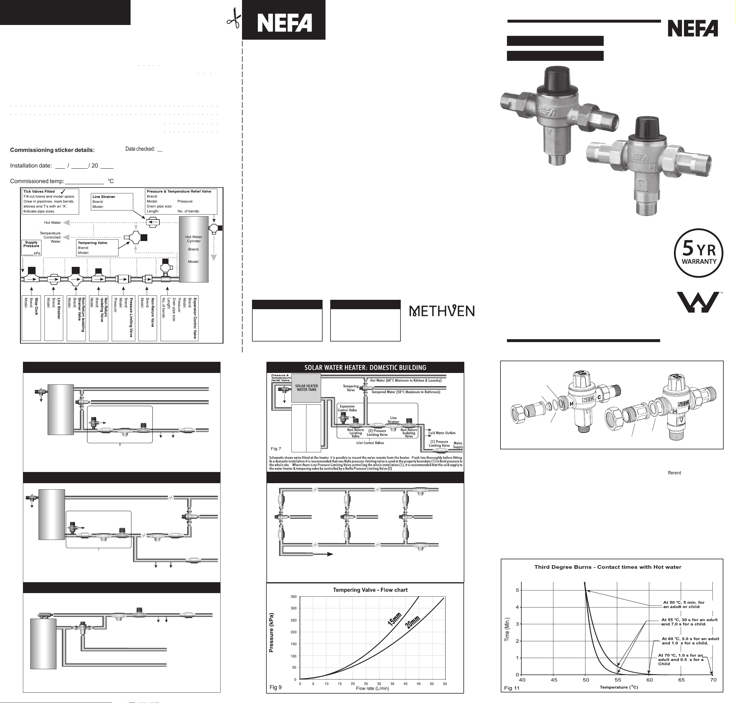
Commissioning sticker details:
Installation date: ___ / _____ / 20 ____
Commissioned temp: ____________ °C
R Yes R No If yes: Brand
Model
○○○○○○○○○○○○
○○○○○○○○○○○○
Date checked: ___________ Temp: ______ °C
Date checked: ___________ Temp: ______ °C
Date checked: ___________ Temp: ______ °C
Date checked: ___________ Temp: ______ °C
Date checked: ___________ Temp: ______ °C
Warranty Statement
The following warranty statement shall apply to all NEFA valve products supplied by NEFA Australia.
Where NEFA valves are installed in a suitable, commercial or domestic application, in addition to any other right or
remedy which the purchaser or end user may have under any relevant consumer protection legislation, Methven
Australia, or any of its subsidiaries, undertake to replace any NEFA brand valve deemed to be faulty by a licensed
plumber.
Further, if any NEFA valve submitted for warranty is found to contain a material defect which arose in the course
of manufacture or does not satisfy the relevant Australian Standards and/or New Zealand Standards product
requirements upon testing, the claimant (licensed plumber) will be reimbursed $50 (See Note 1.)
These undertakings will only apply if:
1. The product was installed by a licensed plumber
2. The warranty claim form is completed in its entirety
3. The product was installed as described in the installation instructions supplied with every NEFA product
4. The product is installed in accordance with the relevant Australian Standards and Plumbing Codes
5. The product was installed as described within the limits of the product specifications supplied with every NEFA product
6. The product has not been tampered with or repaired in any way
7. The product has not been damaged by misuse, accident or neglect
8. The product does not contain excessive debris
9. The product is installed in the specific Country where the original purchase was made
10. The product is submitted to NEFA Australia within 5 years from the date of manufacture.
(See Note 2)
TEMPERINGTEMPERING
TEMPERING
TEMPERINGTEMPERING
VV
ALAL
AL
ALAL
VEVE
VE
VEVE
V
VV
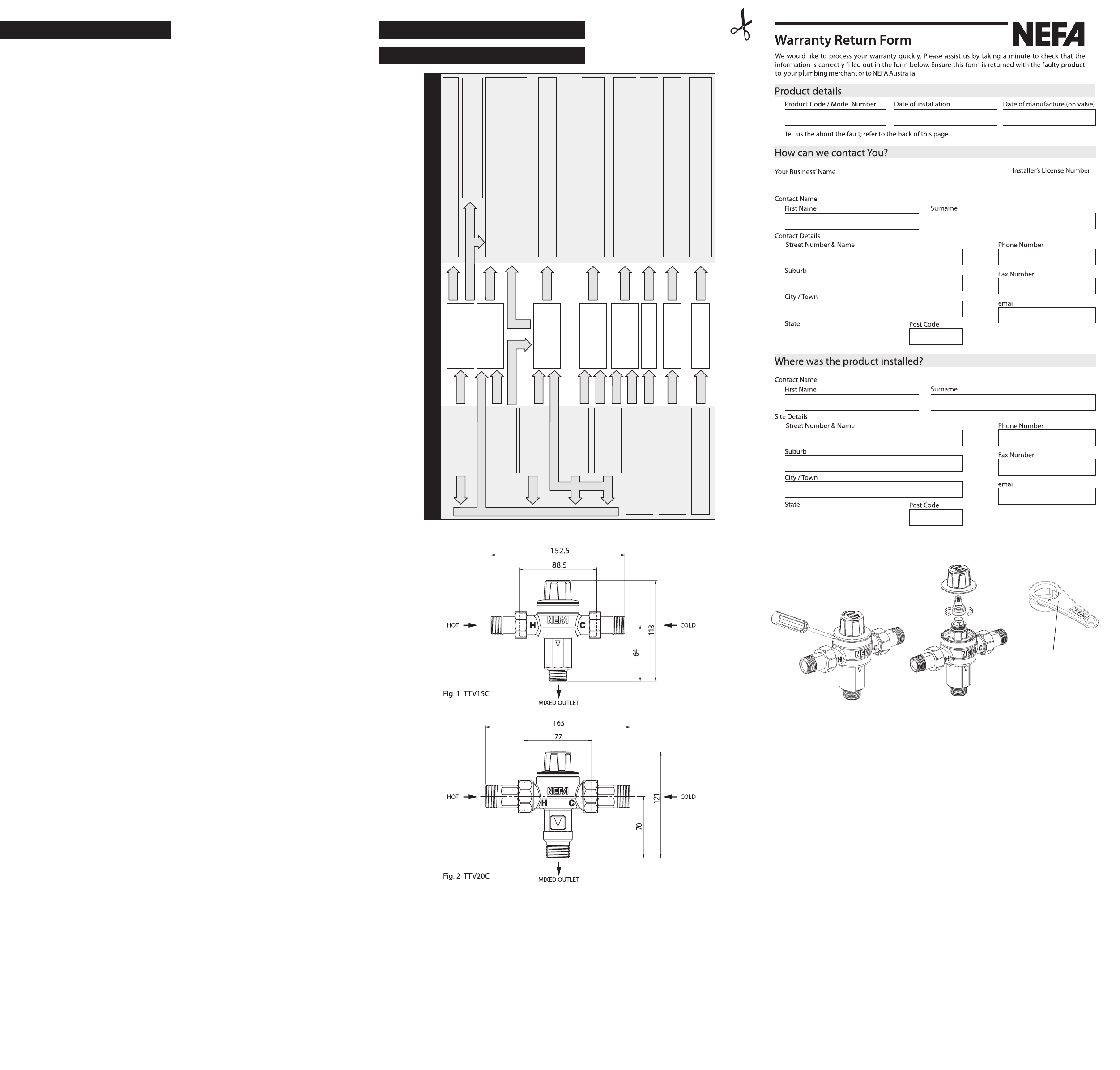
TTV15C
Note 1. Upon submitting a NEFA valve to NEFA Australia for warranty claim purposes, the valve will be tested by
Methven Ltd in accordance with the relevant AS/NZS product standard. If the valve does not meet the requirements
of the product standard, the claimant (licensed plumber) will be reimbursed to a maximum of $50 (incl. GST).
Note 2 The date of manufacture is marked on the valve, represented by a five digit number. The first two digits of
the date of manufacture refer to the last two digits of the year of manufacture. The remaining three digits refer to
the numerical day of the year in which the valve was manufactured (example: 30th June 2007 would be
represented as 07181).
Methven shall in no way be liable to the purchaser or end user of any NEFA valves for any loss, damage (direct,
indirect or consequential), cost or expense suffered or incurred by that person (including, without limitation, any
damage and/or labour charges incurred in installation, repair or replacement), other than as provided in the above
provisions, under any relevant consumer protection legislation or as consented to by Methven in writing in
advance.
CUSTOMER SERVICECUSTOMER SERVICE
CUSTOMER SERVICE
CUSTOMER SERVICECUSTOMER SERVICE
AUSTRALIA
Phone 1300 638 483
Website: www.nefa.com.au
CUSTOMER SERVICECUSTOMER SERVICE
CUSTOMER SERVICE
CUSTOMER SERVICECUSTOMER SERVICE
NEW ZEALAND
Phone 0800 804 222
Website: www.methven.com
Designed, distributed and warranted
by Methven Limited,
Private Bag 19996, Avondale, Auckland, NZ.
285019 Issue E
• Provides accurate safe controlled
temperature water for sanitaty
outlets.
• Hot water shut-off on cold water
supply failure.
• Tamper-proof adjustment.
• Advanced polymers give greater
resistance to calcium deposits.
• Union connections for easy
installation with integral Line
Strainers and Non- Return valves.
• Integral Non Return Valves.
• WaterMark certified.
• Conforms to AS4032.2
TTV20C
WMKA02729
AS4032.2
www.nefa.com.au
(IMPORTANT) Scalds From Hot Water
The following aims to provide information on the risk of Hot water scalds at different water temperatures
and contact time.
The seriousness of a hot water scald burn is directly dependent on the temperature of the liquid and the
length of contact time.
Medical research has demonstrated that there is a significant difference in the time that it takes to get a
serious, third degree scald at different temperatures. A third degree burn is one that goes through the full
thickness of skin and is likely to require surgery.
For water temperatures less than 50ºC, there is a substantial safe contact time before third degree burns
occur. At 50ºC the safe contact time for an adult and a child is 5 minutes. At higher temperatures, the safe
contact time particularly for children and the elderly, is substantially reduced as shown in (Figure 10.) below.
Children and elderly people are more likely to suffer injury than other age groups because their skin tends
to be softer, they are also more susceptible to falls and are less likely to be able to protect themselves.
Extract from AS 4032.2
Page 2
No flow from outlet
Fluctuating or Low
flow rate
Outlet temperature
changes over time
Unstable outlet
temperature
Outlet temperature
not adjustable
Hot or Cold supply from outlet only
Hot or Cold water leaking through
to other supply
Noise
Hot or Cold supply
pressure failure
Line strainers blocked
Fluctuating or incorrect
supply pressures
Hot water supply
temperature fluctuating
or set too low
Valve inlets reversed
Valve incorrectly set
Non-return valves fouled
High water velocity
See AS3500.1
Restore inlet supply pressures and check outlet
Remove valve and inlet connections. Inspect for
blockages and flush if necessary
Remove and clean strainers. If strainers continue to block
additional Nefa line strainers should be fitted to the system
Fit Nefa pressure limiting valves to Hot and Cold supplies
Adjust hot water supply temperature if necessary
See notes 1 and 3. Valve specifications
Re-fit the valve to the correct inlet connections
Re-adjust outlet temperature as required
Re-adjust outlet temperature as required
Clean non-return valves and flush debris from valve
Reduce water velocity.
Achieved via fitting Nefa pressure limiting valves
What is wrong!
Causes How to fix it
SPECIFICASPECIFICA
SPECIFICA
SPECIFICASPECIFICA
TIONSTIONS
TIONS
TIONSTIONS
TROUBLESHOOTING FORTROUBLESHOOTING FOR
TROUBLESHOOTING FORTROUBLESHOOTING FOR
TROUBLESHOOTING FOR
TROUBLESHOOTING FOR
TROUBLESHOOTING FORTROUBLESHOOTING FOR
TROUBLESHOOTING FORTROUBLESHOOTING FOR
• Connections TTV15C 15mm (½" BSP) Male compression
TTV20C 20mm (¾" BSP) Male compression
• Recommended Outlet Temperature range: 40°C - 50°C
• Factory setting: 50°C nominal
(Must be commissioned on site)
• Accuracy of mixed outlet temperature: ±3° - Tested to AS 4032.2
• Cold water supply: 5°C -25°C
• Hot water supply:
TTV15C & TTV20C: (Gas & Electric Storage) 55°C - 90°C
TTV15CHP & TTV20CHP: (Solar Installations) 55°C - 99°C
• Hot water / mixed water temperature differential: 15°C minimum.
• Supply Pressure - Static: 1600kPa maximum
• Supply Pressure - Dynamic: 500kPa maximum
• Maximum permitted pressure variation at inlets: ±10% maximum
(From supply pressure at commissioning)
• Pressure supply differential - Dynamic: 3:1 maximum
(At time of commissioning)
• Minimum flow rate:
For solar installations and applications where fluctuating supply pressures may occur such as
instantaneous water heaters Nefa recommend the installation of a High Performance Tempering Valve.
4 Litres/min
2
1,3
1,3
3
5,6
4
Notes:
1. The minimum hot water storage temperature stated in AS3500.4 Clause1.9 shall
be not less than 60°C to inhibit the growth of legionella bacteria.
NEFNEF
NEF
NEFNEF
A HOA HO
A HO
A HOA HO
T WT W
T W
T WT W
AA
TER SYSTEMSTER SYSTEMS
A
TER SYSTEMS
AA
TER SYSTEMSTER SYSTEMS
2. The valve can be set as low as 35°C or as high as 58°C, depending on site conditions.
These temperatures are outside the optimum working range of the valve and the
requirements of AS 4032.2 and AS3500.
3. This is the minimum temperature differential required between the Hot inlet water
temperature and the Mixed outlet of the valve, to achieve outlet isolation in
accordance with AS 4032.2 in the event of cold water supply failure, providing the
valve is set between the specified adjustable temperature range 40°C to 50°C.
4. The maximum ratio permitted between supply pressures, under dynamic flow
operation. It is recommended at time of commissioning that Hot and Cold pressures
be as equal as possible.
5. The maximum permitted pressure variation in either supply from commissioning
pressures in order to maintain the outlet temperature to ±3°.
6. Note: Steps should be taken to eliminate any causes of rapid changes in supply
pressures, as this may result in an outlet temperature spike greater than ±3° from
commissioned temperature. If a spike occurs it may take a few seconds for the
temperature to stabilize back to within ±3°.
Checks
• Be sure to check site installation parameters (Temperature, Pressure etc.) against the working
specifications of the valve. If these parameters are outside of the stated specifications, they must
be rectified prior to installation.
• Never expose valves to a torch flame or heat. Heat will destroy the seals and sealing parts.
• Never expose valves to freezing conditions. If installed where freezing conditions may occur,
then suitable insulation must be used to prevent damage to the valve.
• Not to be used on Steam supplied systems.
• Not to be used on low–pressure systems.
• The use of excess thread sealant (liquid, tape or any other form) must be avoided as this may
cause the valve to fail.
• A copy of these instructions should be left with the householder for future reference.
The Installation details sticker, should be completed by the installer and attached to the water
heater or other prominent position near the valve or as specified by the local Authority
requirements.
Valve Adjustment
Adjusting tool is marked
to indicate direction for
Hot & Cold temperature
adjustment.
Fig. 3
Operation
• The NEFA Tempering valve is designed to accurately provide safe controlled temperature water
• The Tempering valve will effectively mix to 50
• If the cold water supply to the valve fails then the valve will automatically shut off the hot water
• For installations outside the requirements of AS 4032.2 and AS/NZS 3500.4, the valve can be set
• Strainers are integral to prevent debris entering the Tempering valve that could prevent it working
• Non return valves (NRV’s) are integral to prevent cross feeding of unbalanced supply pressures.
• All working components and critical shut-off faces of the Tempering valve are manufactured from
for outlets primarily used for personal hygiene. The Tempering valve will maintain the outlet
mixed temperature to ± 3
NB: AS/NZS 3500.4 requires hot water to be stored at 60
growth.
supply preventing scalding. 15
set temperature is required to ensure effective hot water shut off in accordance with AS 4032.2.
°C - 58°C. This will depend on site conditions.
to 35
effectively. Installations with poor quality water that could cause the strainers to continually block
should have separate line strainers fitted.
These NRV’s are crucial for the complete hot water system to function effectively and MUST be
fitted to both inlets.
high spec engineering polymers to resist scale build-up. Deposits to similar metal components
would cause them to seize preventing effective and safe operation.
°C from set temperature in accordance with AS 4032.2.
°C when supplied with 55°C hot water.
°C minimum to inhibit legionella bacteria
°C differential between the hot inlet water temperature and outlet
Systems supply pressures.
• Optimum performance of the valve is obtained when Hot and Cold dynamic (flowing) supply
pressures are equal.
• Static supply pressures (non-flowing) will not give a true indication of dynamic pressures.
• In commercial installations it is recommend that separate Nefa pressure-limiting valves be fitted
to both inlets of the Nefa tempering valve for optimum performance.
• In a domestic installation it is recommended that one Nefa pressure-limiting valve is used at the
property boundary to limit pressure to the whole site.
• It is recommended that both Hot and Cold supplies to the valve should be controlled with their
own pressure limiting valves.
Installation
• NEFA Valves shall always be installed by a licensed plumber, in accordance with the NEFA installation
instructions, and the National Plumbing and Drainage Code AS/NZS 3500.4. The installation must also
comply with any Local Authority requirements.
• Before fitting a Tempering valve ensure all debris is thoroughly flushed from the pipe-work prior to
installing. Contaminants and debris are the most common causes of system difficulties.
• A separate un-tempered hot water line to the kitchen and laundry is recommended.
• Do not install a Tempering valve directly onto a hot water cylinder. It is recommended that the valve be
installed as close to the Hot water source as possible for optimum performance.
• The Tempering valve shall be installed where it can be easily accessed for strainer checking and
cleaning, or temperature adjustment.
• The valve must be installed in accordance with the installation diagrams shown in (Figs.4-8).
• If installed at an outlet fixture, 1m of pipe must be installed between the Tempering valve and the outlet.
• Ensure both hot and cold water supplies are connected to the correct sides of the Tempering valve as
marked on the valve body.
Once, installed, EVERY valve must be commissioned by adjusting the valve and measuring the mixed
water temperature at the outlet closest to the Tempering valve. A thermometer must be used.
• Before setting the valve ensure the hot water source is switched on and supplying water within
the specified hot water temperature limits. It is recommended the water heater, if controlled by an
adjustable thermostat should be set to the required 15
thermal shut-off. (See Note.3 of valve specifications).
• Allow the water to flow 1-2 minutes to ensure the mixed water temperature has stabilized.
• A thermometer must be used to test the hot water at the nearest outlet to the installed valve to
ensure the correct mixed water temperature is supplied. Test at a flow rate of not less than 4
litres/minute.
• To adjust the set temperature of the valve you must remove the cap allowing access to the
adjusting spindle.
• Using the adjusting tool supplied, simply rotate the spindle shown in (fig.3) in the direction (H)
hot or (C) Cold as indicated on the tool until the required set temperature is achieved.
• Once the set temperature has been reached and tested with a thermometer the cap must be
snapped back onto the valve to protect the spindle from accidental adjustment, damage or
debris.
° differential temperature necessary for
Servicing and checking requirements:
• It is recommended the NEFA tempering valve be checked annually by a certified plumber to
ensure correct functionality of valve. Space has been provided on the commissioning sticker to
record the date & set temperature of the valve.
• Where the water supply is of poor quality or any other supply variations are likely, it maybe
necessary to check the NEFA valve at more frequent intervals.
• Any temperature checks should be performed at the same outlet at which the valve was first
commissioned. (See installation details sticker details). If the temperature varies more than 2
from the commissioned temperature stated on the installation sticker or is outside of the
requirements of AS3500.4, refer to the NEFA Trouble shooting guide.
• Line strainers and non-return valves are easily accessible through the union connectors for
quick cleaning.
• Where the line strainers continue to block it may be necessary to fit an additional filter or line
strainer into the system.
• This valve is a safety valve and cannot be serviced. If the valve fails to operate it is to be
replaced. No attempt should be made to dismantle the valve. Any attempt to dismantle the valve
(other than union connectors and adjustment cap) will void all warranties.
°C
 Loading...