

Page 1
KIRI CONCEALED THERMOSTATIC SHOWER
WITH DIVERTER (2 OUTLETS AND BATH FILL)
Installation Instructions
Your product should be fitted in compliance with the Water Authority
Regulations. If you are unsure as to what the regulations require, you
can contact your Local Water Authority for further details.
Before commencing installation please ensure that you have :-
Product Care
To maintain a high quality finish of your product , you should avoid using any abrasive detergents.
Some detergents will aggressively attack the surface over a period of time leading to irreversible
damage. Instead, it is advisable to use a soft cloth with warm water . This will significantly
prolong the life and looks of the product. If for some reason you need to use a detergent when
cleaning , only use a low concentrated brand.
Warranty
Methven warrants this product against manufacturing defects and that it is suitable for use
under the general operating conditions specified in this instruction sheet. However, regional
regulations apply and may affect your warranty. Please refer to www.methven.com or call
customer service for full details.
New Zealand Australia UK
0800 804 222 1300 638 483 0800 195 1602
INST ISSUE A294
1. Checked the contents of the box to ensure all parts are present and correct.
2. Read these instructions carefully to understand the installation requirement.
3. Obtained the correct tools to perform a trouble free installation.
4. Considered the surrounding environment where the installation is to take place
and any potential hidden dangers.
Taking the above into consideration should result in a smoother, trouble free installation
Page 2
Index
Item Quantity
Thermostatic Shower Valve 1
Concealing Plate 1
Thermostatic Shower Valve Control Knob 1
Divertor Control Knob 1
Bath Fill Control Knob 1
Screws 4
Wall Plugs 4
Flow Regulator 2
Hexagonal Allen Key 1
Box Contents ...................................................................................
Site Installation Conditions ..............................................................
Operating Requirements ................................................................
Installation .......................................................................................
Maximum Temperature Setting and Adjustment .............................
Parts Reference Drawing ................................................................
Maintenance ...................................................................................
Product Care ...................................................................................
Warranty ................................................................................................................
Page 2
Page 2
Page 3
Page 3
Page 4
Page 5
Page 6
Page 8
Page 8
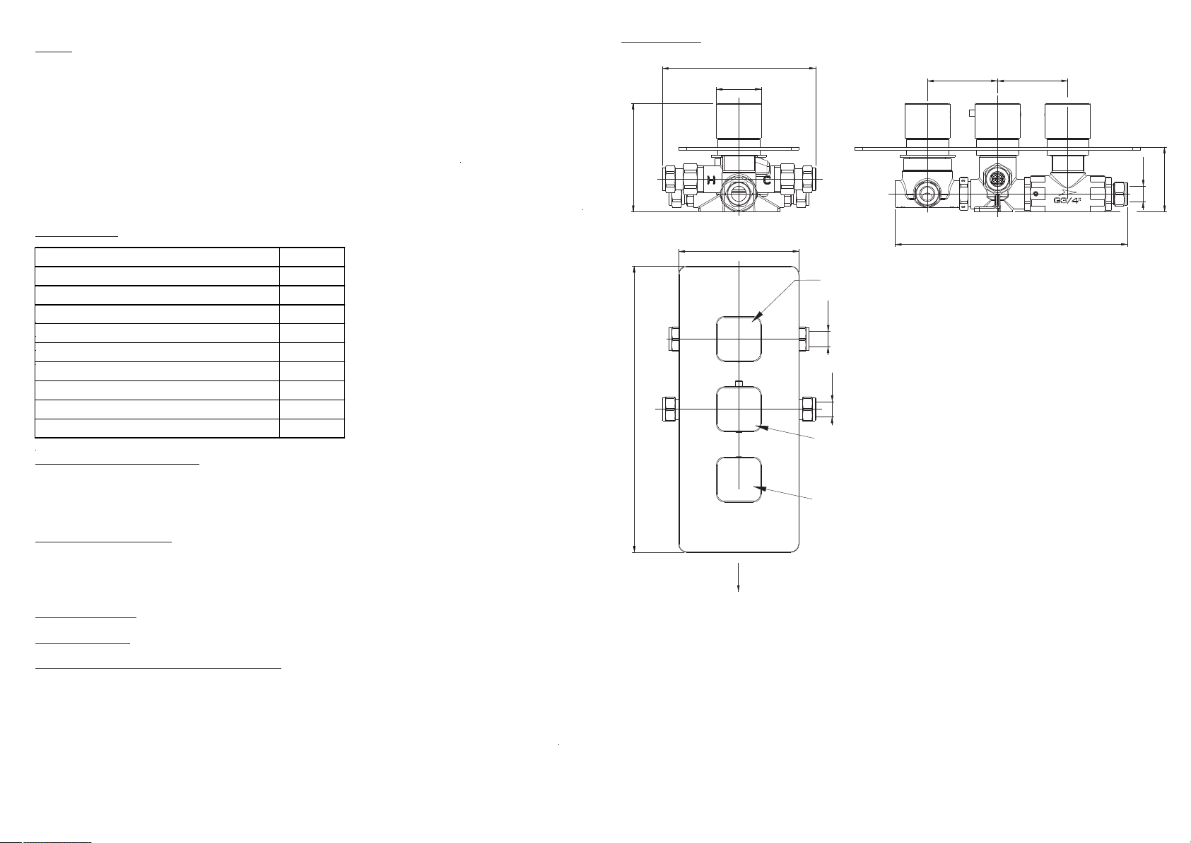
Line Drawing
108
153
45
70
70
Ø15
60 - 67 mm
Box Contents
Site Installation Conditions
Prior to installing your Thermostatic mixing valve it is important to fully understand the site installation
conditions and the location where you intend to install your product. This Thermostatic mixing valve is
designed to be used within the following systems :-
Gravity Fed Hot and Cold
Wherever possible for the best performance of the product, it is always best practice to have equal
pressures supplied to both hot and cold inlets. . However this products will only work up to a maximum
5 to1 Pressure differential.
Unvented Systems
Pumped Systems
Instantaneous Water Heaters (Gas or Electric)
Please note that especially with Electric instantaneous water heaters that a stable flow of water passes
through the heater and the delivered Hot water temperature to the Thermostatic mixing valve is sufficient
to enable the thermostatic mixing valve to work correctly.
Your product should be fitted in compliance with the Water Authority Regulations. If you are unsure as to
what the regulations require, You can contact your Local Water Authority or the Institute of Plumbers for
further details.
2 7
Outlet 1
285
Hot Inlet
120
Bath fill
outlet
Divert to Outlet 1 , Outlet 2 or Bath fill
Ø15
Outlet 2
Ø15
Cold Inlet
Temperature control
Bath fill on / off
231,5
Page 3

Cold Supply Pressure (bar) Hot Supply Pressure (bar) Cold Inlet Port Hot Inlet Port
1 to 5 bar (or Pumped) 1 to 5 bar (or Pumped) Yes Yes
Mains 1.5 to 10 bar Unvented Mains / Mains Pressurised Yes Yes
Mains 1.5 to 10 bar Instantaneous Gas Water Heater Yes Yes
Mains 1.5 to 10 bar Instantaneous Electric Water Heater Yes No
System Configuration Fit Flow Regulator
Maintenance
It is strongly recommended that you perform regular maintenance of your Thermostatic mixing valve to
ensure continued good performance. Failure to regularly maintain the Thermostatic mixing valve may lead
to poor flow , fluctuations in temperature and in some cases complete failure.
To maintain the Thermostatic Mixing valve :-
1. Isolate both Hot and Cold water supplies.
2. Taking note of the Knob positions, Remove both the Diverter knob and Thermostatic mixing valve knob.
3. Remove the Concealing plate.
4. Remove the Plastic temperature stop ring (12) ensuring to note the position on the spindle. This will be
required to be refitted in this position when re-assembling the valve assembly.
5. Remove Shroud (26).
6. Unscrew the Thermostatic mixing valve cartridge anti-clockwise and remove from the valve assembly.
7. Taking care not to alter or damage the cartridge , Soak the cartridge in a suitable descalent and rinse
with warm water.
8. Re-grease any visible seals and refit the Thermostatic mixing valve cartridge to the valve assembly.
9. Refit Shroud (26).
10. Refit Plastic temperature stop ring (12) onto the Thermostatic Mixing valve cartridge spindle in the
position noted in step 4.
11. To ensure the joints are watertight and the valve is re-commissioned correctly , please refer to the
section ‘Installing the product’ , item 5 and follow the sequence through.
Filter Seal Cleaning
Over a period of time the Filter washers (6) located in both the Hot and Cold inlet housings of the
thermostatic mixing valve may become blocked with dirt and debris from your system which could result
in the poor performance of your thermostatic mixing valve. Therefore these filters will periodically require
cleaning. To clean the filters :-
1. Isolate both Hot and Cold Mains supplies.
2. Taking note of the knob positions, Remove bath fill on/off , diverter and thermostatic mixing valve knobs.
3. Remove the Concealing plate.
4. Undo Nuts(s) (19) on both Hot and Cold inlets and remove Filter washers (6).
5. Rinse Filter washers (6) clean and refit into Hot and Cold inlets.
6. Refit Nuts(s) (19) and tighten.
7. Please refer to ‘Installing the Product’ and carry out all steps from items 5.to reassemble the
shower valve and obtain the correct temperature setting.
Operating Requirements
Minimum operating pressure 1 bar *
Maximum operating pressure 5 bar
Maximum Static Pressure 10 bar
*Note : For Gravity systems a minimum distance of 10 metres is required between the bottom of the storage tank
and the showerhead. Failure to ensure this criteria being met may cause the Thermostatic mixing valve to
work incorrectly.
Cold water supply Temperature - Minimum 5°C to Maximum 25°C
Hot water supply Temperature - Maximum 80°C (Recommended Hot water supply temperature 60 - 65°C)
Note: - The minimum temperature differential between the hot and cold water supply should be 50°C. I.e. when
the cold inlet water supply temperature is the hot inlet water supply temperature should be .10°C 60°C
Important Note : To ensure the Thermostatic mixing valve works correctly . The inlet hot water temperature must
be a minimum 10°C above the outlet mixed water temperature of the Thermostatic mixing valve
This product is factory set to an outlet temperature of 38ºC at equal inlet water pressures , but by
using the temperature over ride button the temperature will increase to a maximum of 46ºC.
Fitting Flow Regulators
Important points to note before commencing Installation of your concealed shower mixer.
You should have :-
a. Checked the contents of the box and all parts are present and correct.
b Checked to ensure the minimum site operating conditions can be met.
c. The correct tools to perform a trouble free installation.
d. Considered the surrounding environment where the installation is to take place and any potential hidden
dangers.
e. Isolated both the hot and cold water supplies.
Note : If not already present , you may wish to consider installing isolation valves for ease of future maintenance.
Isolation valves can be fitted anywhere prior to connecting the thermostatic mixer assembly to the water
supply pipes. However , they should always be installed in a safe and convenient place for ease of future
access.
6
Installation
Before securing the Thermostatic valve assembly into the wall cavity. You will need to :-
1. Ensure that both Hot and Cold Supply pipes have been flushed to ensure there is no residual debris within
the supply pipes that may effect the performance of your product. Extreme care should be taken when
carrying out this procedure.
2. Ensure that the Filter washers (6) have been fitted in both inlet ports of the thermostatic mixing valve.
Filter seals are used to protect the delicate thermostatic valve mechanism. Failure to use the
Filter washers (6) provided could damage your thermostatic valve mechanism and will invalidate your
warranty.
3. Decide whether you need to fit the Flow regulators (14) provided into the inlet assembly as shown in the
exploded assembly diagram. In cases where you do need to fit the Flow regulators (14) , please ensure
they are fitted the correct way round as per the diagram. DO NOT INSTALL THESE IF NOT REQUIRED
3
Page 4

Installing the Product
Part Code Description Part Code Description
1 00105055 Valve Body 24 00512119 Connector
2 00142875 Diverter Handle 25 00514592 Connector
3 00142872 Temperature Handle 26 00515537 Shroud
4 00400014 O' Ring 27 00515826 Adaptor
5 00400015 O' Ring 28 00550740 Plate
6 00400246 Filter W asher 29 00601113 Pair of Fixing Screws and Plugs
7 00400380 O' Ring 30 00603719 Check Valve
8 00400648 O' Ring 31 00604189 Diverter Assembly
9 00411240 Spline Adaptor 32 00650492 Thermostatic Cartridge
10 00410544 Handle Cap 33 00940006 Seating Ring
11 00411048 Temperature Over ride Button 34 00400262 O' Ring
12 00411057 Temperature Stop Ring 35 00400008 O' Ring
13 00411171 Plastic Spacer 36 00500219 Grub Screw
14 00411398 Flow Regulator 10 l/min LP 37 00141699 Stopcock Body
15 00500144 Grub Screw 38 00400030 O' Ring
16 00500222 Spring 39 00512115 Connector
17 00500492 Temperature Stop Pin 40 00400100 O' Ring
18 00500700 Grub Screw 41 00512619 Stopcock valve seat
19 00510133 Nut 42 00650307 Stopcock Valve
20 00511135 Nut 43 00515922 Adaptor
21 00511137 Olive 44 00501037 Spacer
22 00511258 Connector 45 00500746 Stopcock Spline Extended Screw
23 00512620 Connector
When installing the assembly into the wall cavity , for ease of installation and maintenance you should aim to
keep the access hole as large as possible whilst ensuring there will still be enough room to be able to create
a suitable contact between the wall and concealing plate using a suitable silicon sealant to create a water tight
joint between the wall and concealing plate.
This product has been designed to fit in a cavity with a minimum depth of 60mm. For deeper cavities you may
need to create a suitable mounting bracket in the cavity to securely mount the valve assembly. We recommend
a mounting depth of between 60/67mm from the front face of the tiles. Failure to take this into account will mean
that the concealing plate will not be able to be fixed onto the valve assembly. Refer to Page 7 ‘Line drawing’.
1. Ensure that both the Hot and Cold mains water supplies are isolated.
2. Fix the shower valve assembly into the wall cavity ensuring the diverter assembly is at the top and the bath
fill on / off control is at the bottom. If done correctly the ‘Hot’ inlet port to the thermostatic mixing valve will be
in the centre of the valve assembly to the left hand side.
3. Connect the respective Hot and Cold water supplies to the Hot and Cold inlet ports of the thermostatic
mixing valve making sure that all seals, filters olives are fitted and joints sufficiently tightened.
4. Connect the left hand diverter outlet to one of your outlets and the right hand diverter outlet to the
other outlet connection and the bath fill outlet to the bath fill.
Important : Before fitting the concealing plate it is essential that all joints are checked for leaks. Failure to do
so could result in flooding or water damage within the cavity over a long period of time that may
not be immediately evident. Therefore :-
5. Secure the Diverter knob (2) to the Diverter assembly (31) and Bath fill on/off knob (2) to the stopcock
assembly.
6. Secure the temperature control knob to the thermostatic mixing valve (32). To secure the temperature
knob in the correct position . Please refer to ‘Maximum temperature setting and adjustment’.
7. Ensuring all joints have been secured and tightened , Turn on both Hot and Cold water supplies.
8. Turn the diverter knob towards the side connected to bath fill outlet.
9. Taking care , turn on the thermostatic mixing valve. If no water appears from the outlet of the bath fill ,
rotate the bath fill on/off knob. Water should now be flowing through the bath fill outlet, check all joints
for signs of leaks . Turn off the bath fill on/off knob. Turn the diverter knob towards one of the other
connected outlets. Water will now flow through this outlet. Repeat this process for the remaining outlet.
Any leaking joints should be immediately rectified. It may be a good idea to leave the shower running for
several minutes to ensure the joints are water tight and no leaks appear.
10. When you are confident that all joints are watertight. Turn off the thermostatic mixing valve.
11. Noting each of the three control knob positions , remove the bath fill , thermostatic mixing valve and
diverter control knobs (The positions will be required after fitting the concealing plate to refit the control
knobs in the correct operating positions).
12. Ensuring correct orientation, Fit the concealing plate (28) to the valve assembly. When fitting the
concealing plate , a suitable sealant should be used to create a waterproof joint between the concealing
plate and wall.
13. Refit and secure the Diverter control knob to the position it was removed in point 11.above.
14. To refit the thermostatic mixing valve temperature knob , Please refer to ‘Maximum temperature
setting and adjustment’.
15. Refit and secure the bath fill control knob to the position it was removed in point 11.above.
Maximum Temperature Setting and Adjustment
Whilst the Temperature of your Thermostatic mixing valve has been factory tested and calibrated, you will
need to perform a slight initial adjustment to suit your system operating setup. To do so :-
1. Loosely fit the Thermostatic mixing valve control knob (3) to the Thermostatic mixing valve. Note, whilst
fitting the Knob, there is a Temperature stop pin (17) inside the knob which is required to line up with the
Temperature stop ring (12).
2. Taking extreme care, Slowly turn on the Thermostatic mixing valve and gently rotate the control knob
to the maximum temperature position. Let the shower run for several minutes to ensure the correct
blend of Hot and Cold water and the maximum outlet hot water temperature has been achieved.
4 5
It is Important to note at this stage, very hot water MAY flow through either outlet depending on
where the diverter is set too and can cause serious burns if care is not taken !!!.
3. Take note of the outlet temperature of the shower using a suitable testing equipment.
4. If the maximum temperature requires adjusting . Remove the Temperature control knob (3) and adjust
the Thermostatic mixing valve spindle.
To increase the outlet temperature , Slowly turn the spindle of the anti-clockwise
To decrease the outlet temperature , Slowly turn the spindle of the clockwise
5. When the desired temperature is achieved. Refit and secure the Thermostatic mixing valve control
knob (3) lining up the pin in the Knob with the Temperature stop ring(12).
6. Turn off the Shower valve.
Parts Reference Drawing
 Loading...