


OPERATING INSTRUCTION MANUAL
MODEL 3200U
ULTRASONIC LEVEL & FLOW MONITOR
AquaMetrix Inc.
22-121 Granton Drive
Richmond Hill, ON
Canada, L4B 3N4
Tel: (800) 742-1413
(905) 763-8432
Fax: (905) 763-9480
www.aquametrix.com

AquaMetrix
Bench Test ·······················································3
Connections·······················································3
Keypad System ····················································4
Menu - Flow Chart ·················································4
Run·····························································6
Totalizer (Flow Mode)··············································6
Password ························································6
Units / Mode ······················································7
Flume Selection ···················································9
Calibration - for Level ·············································10
Calibration - for Open Channel Flow ··································11
4-20mA Current Loop Offset ········································12
Rejection Time ···················································12
Relay Parameters ·················································13
Special Functions ·················································15
Sensor Location - Tank Level········································17
Sensor Mounting/Location - Open Channel ·····························20
Enclosure Installation ··············································23
Error/Warning Messages ···········································24
Field Troubleshooting··············································25
Installation Considerations In Noisy Environments ·······················27
Customer Service ·················································29
Instrument Return Procedure ········································29
Appendix A - Options··············································30
Data Logger ·····················································32
RS232C Serial Output ·············································38
Appendix B - Applications Background································41
Conversion Guide ·················································42
Specifications ····················································43
Calibration Worksheet - Level Mode ··································46
Calibration Worksheet - Flow Mode ··································47
Ultrason
INDEX
IMPORTANT NOTE: This instrument is manufactured and calibrated to meet product specifications.
Please read this manual carefully before installation and operation. Any unauthorized repairs or
modifications may result in a suspension of the warranty.
Page 2

AquaMetrix
QUICK BENCH TEST:
Ultrason
Connect Sensor to the
T.DUCER terminals as shown below, then apply Power. When properly connected
a soft clicking can be heard from the sensor and figures will show on the large LCD display. Test
operation of the Ultrason by holding the sensor steadily and aiming at a flat, stable target 12 to 28" (305
to 711 mm) away from the end of the sensor. Allow a few seconds for the Ultrason to lock onto the
target before displaying its distance. The Ultrason will now display distance in ft or cm (factory
calibration).
CONNECTIONS:
POWER INPUT: The standard model requires AC power input between 100-130VAC 50/60Hz (2 amp
fuse is recommended). No adjustments are necessary for any voltage in this range. Optional 230VAC
requires power input between 200-260VAC 50/60Hz. (See OPTIONS section of this manual for
connection of optional 12VDC or 24VDC power input).
IMPORTANT NOTE
: To comply with CSA/NRTL standards, AC power input and relay connection
wires must have conduit entry to the instrument enclosure.
AMqua etrix
C
N.O
RELAY 1
100-130VAC (50/60 Hz)
OPTIONAL:
200-260VAC (50/60 Hz)
N.C
N.O
RELAY 2
C
C
N.O
N.C
N.C
RELAY 3
G
N
L
IMPORTANT:
MUST CONNECT TO A
GOOD GROUND (<1 Ohm)
WITH 12 AWG CONDUCTOR
4\20
AC
T.DUCER
GND
RX
PU
TX
RS 232
*
N.O
RELAY 4
OPTIONAL
C
N.C
N.O
RELAY 5
C
*
C
N.O
N.C
GROUND STUD
IMPORTANT
ATTACH CABLE
SHIELDS (4-20mA, RS232)
THIS END ONLY
N.C
RELAY 6
:
ALUMINUM CHASSIS
Page 3
AquaMetrix
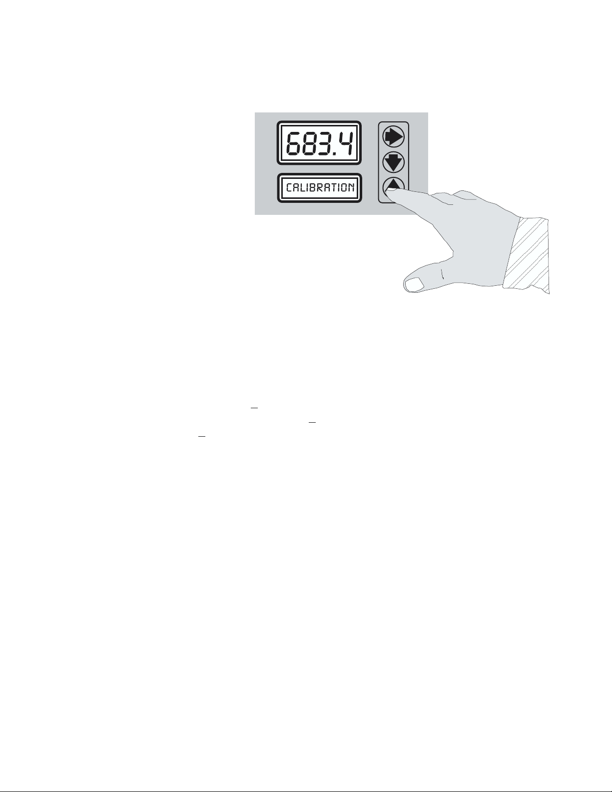
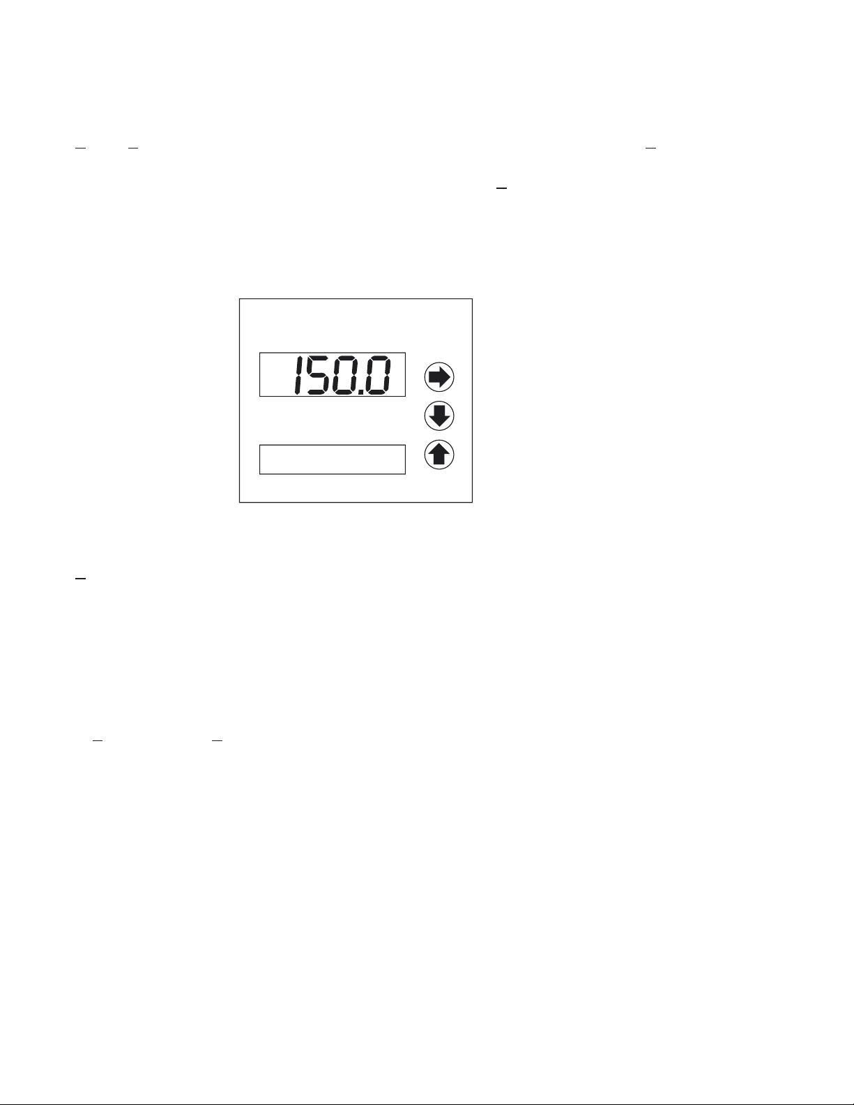
KEYPAD SYSTEM
The Ultrason has a simple 3-button
calibration system. Operating and
calibration modes are shown on the
16-digit alphanumeric display. The
keypad is used to move around the
menu to calibrate the Ultrason, and to
view operating mode and functions. A
beep is sounded as each key is pressed.
If the keypad is not used for 2 minutes,
the Ultrason will automatically go to
RUN mode (scrolling display). Use the
keypad to explore the Menu and
become familiar with its features.
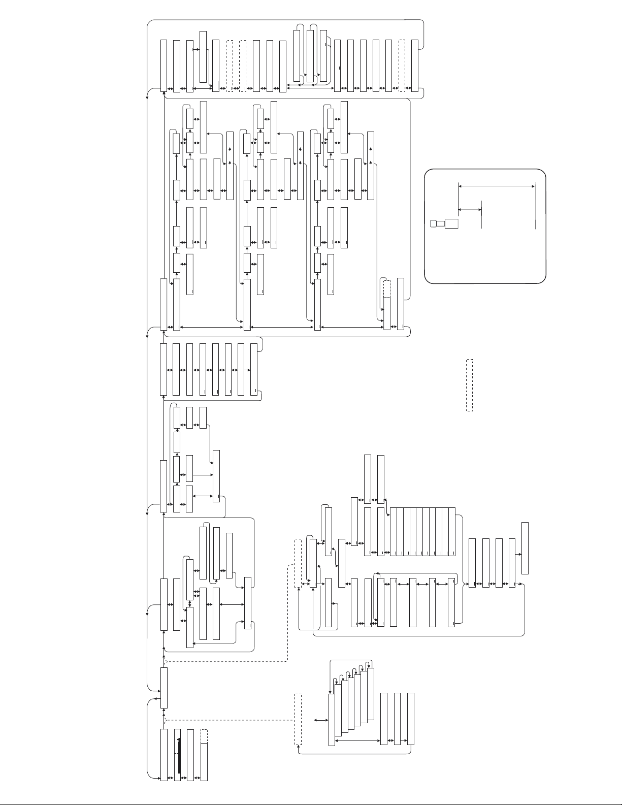
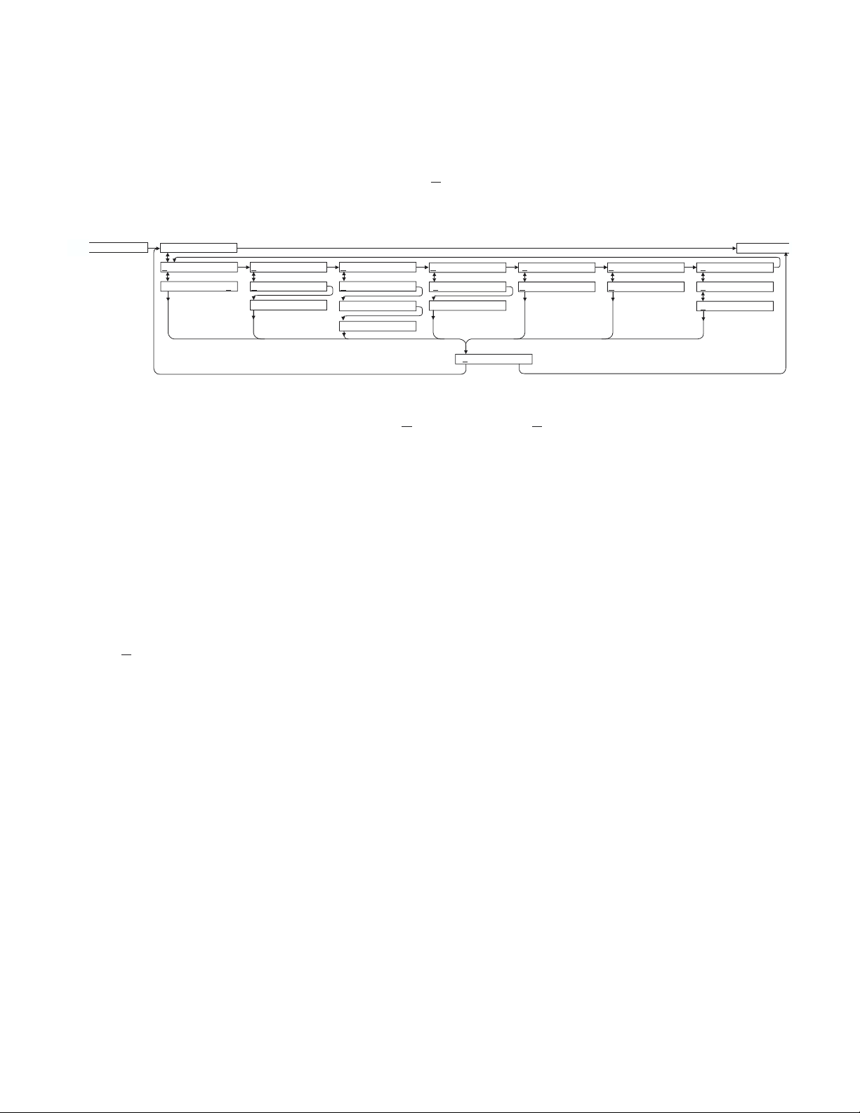
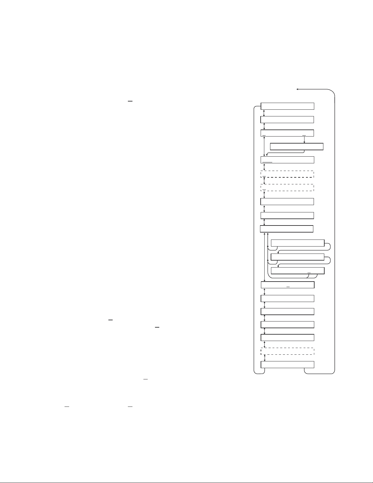
MENU - FLOW CHART
Ultrason
The following diagram shows part of the Ultrason Menu system. Arrows show the three directions to
leave a box. Pressing a corresponding keypad arrow will move to the next box in the direction shown.
Move the cursor (or underline) under numerals to increase or decrease the number with the ÈÇ keys.
At the bottom of each Menu column is a
(even through power failure), move the cursor under
pressed with the cursor under
the Menu column.
Store? no changes will be stored and the system will return to the top of
Store? Yes box. To store the calibration values permanently
Yes and press the È or Ç key. If the È key is
Page 4
V 2.51
O
SLT32
SPECIAL FUNCTION
1234567890123456
Tag 01
VYiew Codes? es
23:39:51
Time
Date May 31/1999
30 s
LOE Time
Yes
Tot?
Reset
Cº
20.3
Temp
Cº
20.0
Min Temp
Cº
23.0
Max Temp
DISPLAY FCºº
0.00%
4.000
20.000
Simul
20mA ADJ
4mA ADJ
ISB?: oYesN
Yes
Store?
New Password: 00
Com 24 48 96 192
N MENU
RELAY PARAMETERS
CALIBRATION
Flow
Level
Temp
Pulse
R1 Function Off
1.333 ft
MinRg
HiAlm
LoAlm
R1 Mode Pump
R1on 0.00 C°
R1on 0.00 ft3
32.00 ft
MaxRg
R1 on 0.00ft3/s
R1 OFF 0.00 ft
R1 on 0.00 ft
° C
OFF
R1 0.00
0.00 %
100.00 %
20mA @
4mA @
Hold
On
R1 LOE Off
%
08 s
20
RejTime
Damping
Flow
Level
Temp
Pulse
R2 Function Off
Yes
Store?
HiAlm
LoAlm
R1 Mode Pump
R1on 0.00 C°
R1on 0.00 ft3
R1 on 0.00ft3/s
R1 OFF 0.00 ft
R1 on 0.00 ft
° C
OFF
R1 0.00
Hold
On
R1 LOE Off
Flow
Level
Temp
Pulse
Function Off
R3
HiAlm
LoAlm
R1 Mode Pump
R1on 0.00 C°
R1on 0.00 ft3
R1 on 0.00ft3/s
R1 OFF 0.00 ft
R1 on 0.00 ft
° C
OFF
R1 0.00
Hold
On
R1 LOE Off
(123456)
ALT
Yes
Store?
MIN
SENSOR
RANGE
OPTIONAL FEATURES
MAX LEVEL
MAX
RANGE
ZERO LEVEL
Ultrason - CALIBRATI
FLOW MODE ONLY
FLUME SELECTION
UNITS / MODE
PASSWORD: 00
K=
Custom
More
Sizes
Parshall
Sizes
V-Notch
cm %
Vol Hrt Flow
m
in
Level
ft
Range
n=
Yes
Store?
L
m3
VSG USMG
IG IMG
ft3
L
USG IG m3
Mx Vol xxxx.x ft3
ft3
123456
LoAlm
5.0 ft3/s
HiAlm
At:
Event
1
Time
Trend
Formatted
StartJan 01/2000
Flow
MAX
AVERAGE
TOTAL
Daily
Daily
Daily
TIME
Flow
MAX
Flow
MIN
Daily
StartJan 01/2000
03:02:16
Start
TIME
Flow
MIN
Log Site ID
Setup
s min hr d
Yes
Store?
DATA LOGGING
24 HR LOG
ONLY IF ENABLED
SHOWS 24 Hr FORMAT
STOP
RUN
1
Session No
->
01/2000
Jan
03:02:16
Start
Interval: 30 Sec
Isnterval: 24 Hr
Interval: 12 Hrs
->
31/1999
Days
Dec
255
5 Sec
2 Sec
Interval: 10 Sec
Interval:
Interval:
s
Hr
Interval: 8
-
data
more
no
-
1 Sec
5 Min
Interval:
Interval: 30 Min
Interval: 10 Min
Interval:
s
Hr
Interval: 4
2 Min
1 Min
Interval:
Interval:
Hr
Isnterval: 1
WrapAround? Yes
Yes
Reset Log?
26640 Hrs Left
Yes
*** STORING ***
Store?
RUN
FLOW MODE ONLY
C
RELAYS:
Tot:
E
AquaMetrix
o
RUN
Ultrason
A scrolling display shows the units selected from the
UNITS/MODE column, the mode of operation (Range, Level or
Flow), the full scale value for the large numeric display, Totalizer
value (in
FLOW mode), and air temperature at the sensor location.
RUN
EC
FLOW MODE ONLY
Tot:
RELAYS:123456
PASSWORD: 00
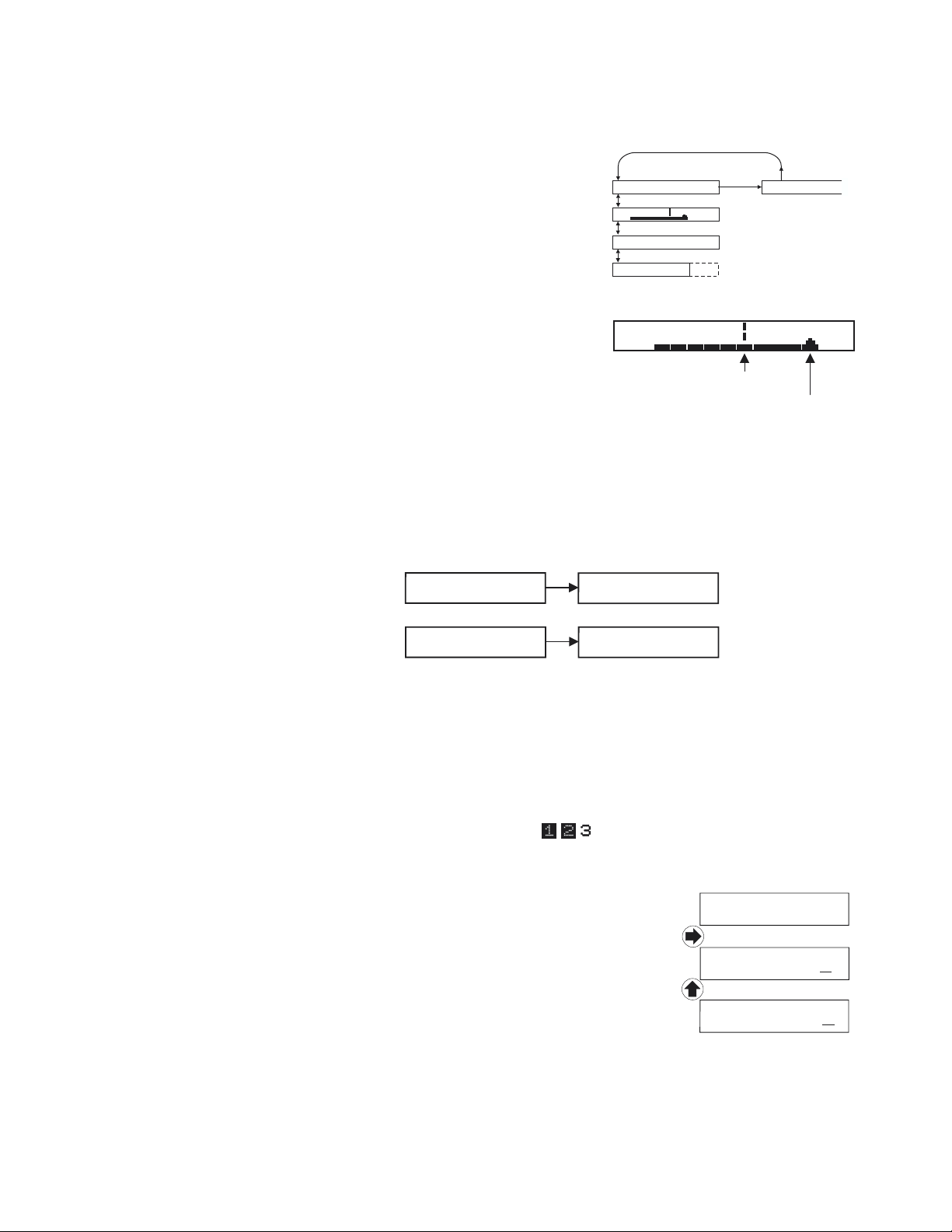
ECHO CONFIDENCE
EC
Echo Strength is automatically adjusted by the Ultrason in response
to operating conditions in the applications.
From RUN use È to get to the Echo Confidence display,
EC.
Minimum
Marker
Current
Echo Strength
Arr
w
TOTALIZER
The Totalizer display will only be enabled when the Ultrason is calibrated in
FLOW mode. From RUN
use È or Ç keys to display Tot: value. The Totalizer value is updated every 2 seconds with flow
volume > 1 litre (0.264 USG). The display will show up to 10 digits and then restart at 0 automatically.
Units: ft³, USG, IG, L
T: 9999999999
TOT: 0
Units = m³
Press È or Ç keys to return to
RUN.
The totalizer can be reset to zero by going Æ to
T: 0283168470
SPECIAL FUNCTION and È to Reset Tot?.
TOT: 0
RELAY STATUS DISPLAY
Press È from
Engerized relays will be displayed in reverse type
Tot: to RELAYS 1,2,3.
RELAYS:
PASSWORD
The password (a number from
CALIBRATION menu.
From
RUN (scrolling display) press Æ to PASSWORD.
00 to 99) prevents unauthorized access to the
Press Æ to place the cursor under the digits and È or Ç to change the
number and then Æ to proceed to
CALIBRATION.
PASSWORD: 00
PASSWORD: 00
PASSWORD: 01
Factory default Password is
and È to New Password.
00. A new password can be stored by going Æ to SPECIAL FUNCTION
Page 6
AquaMetrix
UNITS / MODE
Ultrason
Press Æ to
DATA LOGGING
Range Level
UNITS/MODE, then È . Press Æ to move the cursor under the required measurement units:
ft - feet
in - inches
m - meters
cm - centimeters
% - percent
UNITS / MODE
ft in m cm %
Vol Hrt Flow
ft3 USG IG m3 L
Mx Vol xxxx.x ft3
Store? Yes
ft3 USG USMG
IG IMG m3 L
s min hr d
FLUME SELECTION
Press È to
Range mode displays distance from the sensor to the target or liquid surface like a tape measure.
Range Level > Vol Hrt Flow.UseÆ to select the operating mode of the Ultrason.
Range mode is useful to measure the exact distance from the sensor to the zero level during
calibration, or to monitor “outage” or free space in a tank.
Level mode can be used to measure tank level in linear units, or “Head” (height of flow) in an open
channel for comparison with a flume manufacturer’s flow tables.
Vol Volume mode displays tank inventory in engineering units like gallons or liters.
Hrt Horizontal Round Tank mode sets the Ultrason to calculate and display volume units in a
horizontal round tank.
Flow mode is for open channel flow through a flume or weir.
From
Vol Hrt or Flow press È to make your selection. (Range or Level mode will bypass the
Volume units selection menu).
Vol Hrt or Flow modes will give you the additional choice of
volumetric units:
ft3 - cubic feet
USG - US gallons
USMG - US million gallons (FLOW only)
IG - Imperial gallons
IMG - Imperial million gallons (FLOW only)
m3 - cubic meters
L - liters
Press Æ to position the cursor underneath your selection and press È to make your selection.
Page 7
AquaMetrix
Vol or Hrt modes will also prompt you to enter a maximum volume. Press È from MxVol to position
Ultrason
the cursor under the first digit. Use È or Ç to change the digits or decimal point to enter the actual
maximum volume you will be measuring. Press Æ to return to
MxVol and È .
You can enter values up to 6 digits (e.g. 150,000 liters). When the measured tank volume exceeds 4
digits, the Ultrason will automatically display a 'multiplier' on the lower alphanumeric display.
AMqua etrix
= 150,000 Liters
UNITS 1000L
FLOW mode will offer the additional selection of time units:
s - seconds
min - minutes
hr - hours
d - day
Note: The Ultrason will display
value of 9,999,999. Use
to
Store and Æ to Yes. Then press È or Ç to store all your UNITS/MODE selections.
US MGD, Imp MGD or m3/d so that Units will be 9,999,999 or less. Press È
Er:ILLEGAL UNITS if your choice of Units exceeds a maximum
Page 8
AquaMetrix
FLUME SELECTION
The
FLUME SELECTION menu will only appear in FLOW mode.
Use È and Æ to select the correct Flume or Weir.
Ultrason
UNITS/MODE
Use È and Æ again to select the Size then È to
Press È or Ç to store flume selection and get to
FLOW MODE ONLY
FLUME SELECTION
V-Notch More> P. Bowlus More> L.Lagco More> Rect. Weir >
22.5 30 45 60 09
Parshall More>
2" 3" 6" 9" >
12" 18" 24" 36">
4" 6" 8" 10">
12" 15" 18">
21" 24" 42">
6" 8" 10" 12" >
18" 24" 30" 36">
Store? Yes
Size 1.000 ft
Store? and Æ to Yes.
CALIBRATION mode.
Rect.Weir w/EC >
Size 1.000 ft
Custom More>
K = 1.0000
N = 1.0000
CUSTOM FLUMES: Experimental or empirical data for any flume or weir can be reduced to an
equation of the form
Q is flow volume
K is as scaling factor which includes flume size and units of flow measurement
n describes the flume non-linearity
H is the level being measured
Use the AquaMetrix Utility program
Select
n: enter an 'n' constant.
CUSTOM for flumes or weirs not listed in the Menu. At the K: prompt enter a 'K' constant. At the
Q=KHn where:
FIND K&n.exe to determine K and n constants from entered data.
CALIBRATION
Page 9

AquaMetrix
Ultrason
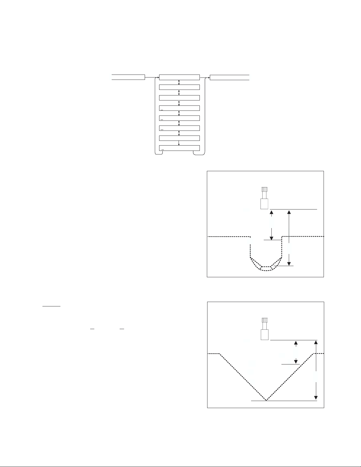
CALIBRATION
- for Level/Inventory Applications
1. Before starting the calibration determine:
a) MAX RANGE = ________________
(Maximum range = distance from Sensor to Zero
level)
b) MAX LEVEL = ________________
(Maximum level of product being measured)
c) MIN RANGE = ________________
(Distance from sensor to Max Level)
Minimum range = MAX RANGE - MAX LEVEL
(must be at least 8" / 203 mm depending on sensor
model)
2. Check the maximum range with the sensor installed by:
a) Use Æ to get to
Range, then Store? Æ Yes
UNITS/MODE then È to get to
(NOTE: liquid must be at zero level)
or
b) Carefully measure distance from sensor to zero
level with tape measure.
TANK INVENTORY
LEVEL MODE
0%
0%
MIN RANGE
MIN RANGE
100%
TANK INVENTORY
RANGE MODE
SENSOR
MAX RANGE
SENSOR
MAX RANGE
MAX LEVEL
MAX
VOLUME
ZERO LEVEL
MAX LEVEL
MINIMUM RANGE:
CALIBRATION
At
- Press È to get to MinRg
- Press Æ to move the cursor under the digits
-UseÈ or Ç to set the minimum range
MinRg must be ³12" (30.5 cm) for US2-1A1A
Note:
sensors and ³ 16" (40.6 cm) for US2-2A1B sensors except
in
Hrt mode. For correct tank volume calculation in Hrt
mode MinRg must be the actual distance from the end of
the sensor to the top of the tank (any value ³0). In
Level
or Range modes the Ultrason will only accept MinRg
values ³ 8" (20.3 cm).
- Press Æ to return to
MinRg
MAXIMUM RANGE:
Press È to get to
MaxRg
Repeat as for MinRg
100%
TANK INVENTORY
HORIZONTAL ROUND TANK (HRT) MODE
MIN RANGE
MAX
VOLUME
MAX RANGE
ZERO LEVEL
Page 10
AquaMetrix
CALIBRATION
- for Open Channel Flow
Ultrason
FLUME SELECTION
CALIBRATION
MinRg 1.333 ft
MaxRg 32.00 ft
4mA @ 0.00 %
20mA @ 100.00 %
Damping 20 %
RejTime 08 s
Store? Yes
1. Before starting the calibration determine:
a) MAX RANGE = ____________________
(Maximum range = distance from the Sensor to Zero
level point)
b) MAX LEVEL = ____________________
(Maximum level of flow through flume or weir)
c) MIN RANGE = __________________
(Distance from sensor to Max Level)
Minimum range = MAX RANGE - MAX LEVEL
(must be at least 8" / 20.3 cm depending on sensor
model).
RELAY PARAMETERS
PALMER BOWLUS
SENSOR
MAX LEVEL
MIN
RANGE
MAX
RANGE
ZERO LEVEL
2. Check
a) Use Æ to get to
the maximum range with the sensor installed by:
UNITS/MODE then È to get to
Range, then Store? Yes
(NOTE: flow must be at zero flow)
or
b) Carefully measure distance from sensor to zero level
with tape measure.
Page 11
V-NOTCH
SENSOR
MIN
RANGE
MAX LEVEL
MAX
RANGE
ZERO LEVEL

AquaMetrix
4-20mA CURRENT LOOP OFFSET
Some applications may require the 4-20mA output to be offset so that 4mA or 20mA corresponds to a
Level, Range or Flow other than Zero and Full Scale.
4mA at - use Ç and È to set % output for 4mA. It is adjustable from -5% (3.8mA) up to 15% lower
than the 20mA setting. Adjustment resolution is 0.05% (0.01mA).
20mA at - use Ç and È to set % output for 20mA (down to 15% greater than the 4mA setting and up
to 300%). Adjustment resolution is 0.05% (0.01mA).
DAMPING
Minimum damping allows fast response to level changes. Increasing damping slows the Ultrason's
response to level changes and is ideal to smooth the display and outputs in turbulent conditions.
Damping value is shown in percent (0-99%). Some experimentation may be required to select the
optimum damping value. A value of 20% is recommended for most applications. For fast level changes
(up to ½ inch/sec - 13 mm/sec), a
Damping value of 1% is recommended. Maximum is 99%.
Ultrason
If the Ultrason is unable to obtain repeated echoes the Damping setting will be automatically set to 1%
by the instrument.
REJECTION TIME (RejTime)
Rejection Time adjustment is a powerful Ultrason feature to suppress false echoes and the effects of
transient targets such as agitators, splashing, or turbulence. Rejection Time is shown in seconds. The
time value represents the number of seconds the Ultrason must receive repeated echoes from a new
target before indicating its level on the display and outputs. The factory default is 8 seconds and should
be ideal for most applications. Decreasing this value allows the Ultrason to respond more quickly to fast
level changes, and increasing the time value allows the Ultrason to reject false echoes from slow
sweeping agitators, tank filling streams, splashing, severe turbulence and steam. Minimum setting is 1
second (for fast level changes up to 1/2 inch/sec - 13 mm/sec). Maximum setting is 85 seconds. If the
Ultrason is unable to obtain repeated echoes the
by the instrument.
RejTime setting will be automatically set to 1 second
Page 12
AquaMetrix
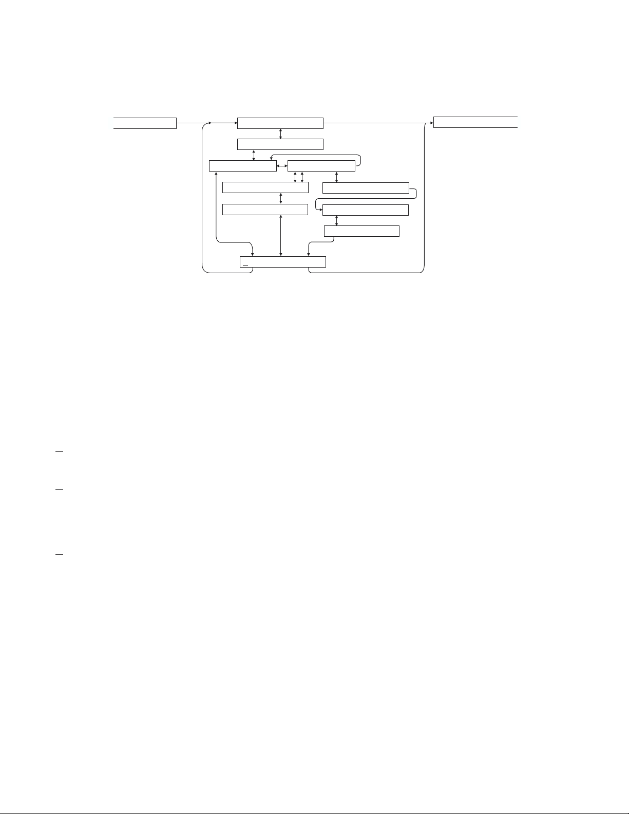
RELAY PARAMETERS
Ultrason
Each relay can be individually calibrated. Press È to
ÆTemp Æ Level Æ Flow.
Off
Pulse
CALIBRATION
mode means the relay will not be energized
Appears in Flow mode only. Press È and set digits to the flow volume increment required
RELAY PARAMETERS
R1on 0.00 ft3
R2 Function Off
Pulse
Pulse
TempR1 Function Off
R1on 0.00 C°
R1 0.00
OFF
Temp
between relay pulses. Use this feature for remote samplers, chlorinators or totalizers.
Minimum time between pulses is 1 second and pulse duration is 350 milliseconds.
R Function and Æ to select: Off Æ Pulse
SPECIAL FUNCTION
Level Flow
R1 Mode Pump LoAlm
° C
R1 on 0.00 ft R1 on 0.00ft3/s
R1 OFF 0.00 ft
R1 LOE Off
Level Flow
On
HiAlm
Hold
Temp References temperature reading from the Ultrason's ultrasonic sensor (air temperature at
the sensor location). Press È and Æ and set the relay On and Off set points.
Level
Range
Volume
Appears in Level, Range, Volume or HRT modes only. Press È to R Function and Æ
to select
Pump mode - press È and Æ and set relay On and Off set points.
LoAlm mode - press È and set relay On point. Relay will be On with levels below
Pump, LoAlm (low alarm) or HiAlm (high alarm).
this point.
HiAlm mode - press È and set relay On point. Relay will be On with levels above
this point.
LOE - press Æ to select Off ÆOn Æ Hold. In a loss of echo condition, the
(Loss Of Echo) relay will turn Off (de-energize), On (energize) or Hold its current state.
Each relay can be individually configured. Press È.
To calibrate a relay for echo loss alarm only, set the relay On and Off set points to exactly
the same value, and then set
LOE to On mode. The relay will now energize only when an
echo loss condition occurs.
Page 13

AquaMetrix
Ultrason
Flow
Appears in Flow mode only. Press È to R Function and Æ to select Pump, LoAlm
(low alarm) or HiAlm (high alarm).
Pump mode - press È and Æ and set relay On and Off set point.
LoAlm mode - press È and set relay On point. Relay will be energized with levels
below the On point and de-energized with levels above the On point.
HiAlm mode - press È and set relay On point. Relay will be energized with levels
above the On point and de-energized with levels below the On point.
LOE - press Æ to select Off ÆOn Æ Hold. In a loss of echo condition, the
(Loss Of Echo) relay will turn Off (de-energize), On (energize) or Hold its current state.
Each relay can be individually configured. Press È.
ALT permits relays calibrated in Pump mode to be
alternated automatically. Pump alternation
allows even pump wear in pumping station
applications.
ALT (-None-) indicates that no relays have
been programmed in Pump mode.
ALT 123 - Press Æ to place cursor (underline)
under the relay number to be programmed for
alternation and press Ç or È to highlight.
Repeat until all relays to be alternated are
highlighted.
PUMP ALTERNATION (R1, R2, R3)
LAG
PUMP 1
2
3
1
1st CYCLE
2nd CYCLE
3rd CYCLE
...ETC
LEAD
PUMP
1
2
3
LAG
PUMP 2
3
1
2
Press È to
Store? Yes and Æ to Yes. Press Ç or È to save your Relay settings.
Page 14
AquaMetrix
SPECIAL FUNCTIONS
SLT32 V2.26 shows software version installed
Ultrason
View Codes? Yes
Select Yes and then È to display an
instrument performance code. Faults detected
by the instrument are stored in the code and
will be requested by AquaMetrix if you call
for service or assistance.
Tag Enter Instrument Tag number (0-9999)
Date MM DD/YYYY
(with optional Data Logger) Press Æand Ç or
È to change Month, Day Year.
Time HH:MM:SS
(with optional Data Logger) Press Æ and Ç or
È to change Hours, Minutes, Seconds
LOE TIME
Press Æ and Ç or È to change the number of
seconds without receiving an echo before the
Ultrason displays
ECHO LOSS, and Control
relays change state as calibrated under Relay
Parameters.
Factory default is 30 seconds and is
recommended for most applications,
Minimum is 10 seconds and maximum is 60
seconds.
SPECIAL FUNCTION
SLT32 V 2.26
VYiew Codes? es
1234567890123456
Tag 01
Date May 31/1999
Time 23:39:51
LOE Time 30 s
Reset Tot? Yes
Temp 20.3 Cº
Min Temp 20.0 Cº
Max Temp 23.0 Cº
DISPLAY FCºº
ISB?: N Yeso
Simul 0.00%
Reset Tot? Yes (FLOW mode only) Position the cursor under
Yes to reset the totalizer. Store this selection
at the
Store? Yes prompt.
Temp 25.0°C Indicates current temperature at the sensor
head. Press Æ to
Temp
to display the minimum and maximum
Min Temp and Æ to Max
temperatures the Ultrason has sensed. Press Æ
to Display °
C °F. Position the cursor under °C
4mA ADJ 4.000
20mA ADJ 20.000
New Password: 00
Com 24 48 96 192
Store? Yes
for celcuis display or °F for Farenheight
display. Press È to return to
ISB?: No Yes Select Yes only when the instrument is equipped with an optional Intrinsic
Temp.
Safety Barrier for sensor mounting in hazardous locations. This setting
compensates for the electrical characteristics of an Intrinsic Safety Barrier.
Page 15

AquaMetrix
Simul The Output simulation function controls the 4-20mA output, digital display
and control relays. Use it to simplify calibration of remote devices such as
chart recorders or remote displays, and to test Relay set-points. Simulation
digits are shown as a percentage of full scale. Use the Çand ÈArrow keys to
simulate
Increments will automatically accelerate when the Çor È is continuously
pressed.
0% (4mA), 100% (20mA), and increments of .05% (.008mA).
Ultrason
4mA ADJ
20mA ADJ
New Password position cursor under digits and set new number between 00 and 99.
Com 24 48 96 192 Optional (with Data Logger) Speed of RS-232C transmission. Select 2400,
Use to fine tune the 4mA and 20mA calibration of the 4-20mA output.
Adjustment range is +1mA to –1mA in 0.002mA steps
Important
during these adjustments.
4800, 9600 or 19200 baud rate (must be set to match baud rate in
‘AquaMetrix Logger’ software and any modems used for serial
communication).
: The 4-20mA output will be forced to 4mA and 20mA respectively
Page 16

AquaMetrix
OO
Ultrason
INSTALLATION - SENSOR LOCATION
- Tank Level/Inventory Applications
Each Ultrason Level Transmitter includes a
non-contacting ultrasonic sensor. The sensor must be
installed in a position to obtain unobstructed echoes
from the liquid or material being measured.
Mount the sensor away from pipes, ladders, or
structural members which might cause continuous
false echoes.
SOLIDS AND POWDERS
SENSOR MOUNTED
AWAY FROM MATERIAL
PATH. COARSE SOLIDS
WILL USUALLY RETURN
AN ECHO EVEN IF AT
AN ANGLE
BAD G
D
90°
FINE POWDERS
MAY NEED SENSOR
TILTED NORMAL TO
SURFACE TO OBTAIN
GOOD ECHOES
Page 17

AquaMetrix
A
0
SENSOR MOUNTING LOCATION
- Tank Level/Inventory Applications
1 FT (30 cm) HORIZONTAL
FROM SIDEWALL FOR
EVERY 10' (3 m) VERTICAL
NOTE: 2 FT (60 cm) FOR
EVERY 10' (3 m) DEPTH ON
PPLICATIONS WITH ROUGH
SIDEWALLS, LADDERS,
REINFORCING RINGS ETC.
PREFERRED SENSOR
LOCATION
SENSOR FACE MUST
BE HORIZONTAL ±1°
Ultrason
6" SCHEDULE 4
STAND PIPE IF
EXTENSION
REQUIRED
MAX. LIQUID LEVEL
SENSOR MOUNTING
Each sensor is equipped with a 3/4 inch “isolation coupling” which MUST be used in your installation.
A threaded nipple or length of conduit may be used to position the sensor at the desired height.
The sensor should be hand-tightened (like a light bulb) by turning the sensor stem only. DO NOT use a
wrench and do not over tighten. DO NOT clamp the sensor below the isolation coupling.
Page 18

AquaMetrix
Notes:
1. Use the ¾" NPT "Isolation Coupling"
supplied and only. Do
not clamp sensor body or stem.
2. Locate the sensor 1 ft (30 cm) from
the sidewall or obstruction for every
10 ft (3 m) depth.
3. mount in direct sunlight.
Do not
4. Extend sensor cable up to 500 ft
(150 m) with RG62AU coaxial only.
CROSS BAR MOUNT
CLAMP
DO NOT
CLAMP IN
THIS AREA
hand tighten
3/4"
CONDUIT
ISOLATION
COUPLING
(SUPPLIED)
MUST BE
USED
FLANGE MOUNT
4" OR 6" BLIND FLANGE
TAPPED ¾" NPT
¾" NPT
NIPPLE
DO NOT
CLAMP IN
THIS AREA
FLEXIBLE
CONDUIT
ISOLATION
COUPLING
(SUPPLIED)
MUST BE
USED
CONDUIT MOUNT
Ultrason
JUNCTION
BOX
(OPTION JB)
3/4"
CONDUIT
STANDPIPE LENGTH
AS SHORT AS POSSIBLE
STANDPIPE DIAMETER
AS LARGE AS POSSIBLE
TYPICAL STANDPIPE:
4” / 100 mm DIAMETER
12” / 300 mm LENGTH
NARROW DIAMETER
STANDPIPES (<4” / 100 mm)
MAY AFFECT ACCURACY
OF READING
STAND PIPE MOUNT
SMOOTH
GRIND OR FILE
PIPE EDGE
DO NOT
CLAMP IN
THIS AREA
3/4" NPT
DO NOT
CLAMP IN
THIS AREA
ISOLATION
COUPLING
(SUPPLIED)
MUST BE
USED
ANGLE MOUNT
NIPPLE
ISOLATION
COUPLING
(SUPPLIED)
MUST BE
USED
Page 19

AquaMetrix
Ultrason
SENSOR MOUNTING/LOCATION
- Open Channel Flow Applications
Each sensor is equipped with a 3/4 inch isolation coupling which MUST be used in your installation. A
threaded nipple or length of conduit may be used to position the sensor at the desired height. The
sensor should be hand-tightened by turning the sensor stem only. DO NOT use a wrench and do not
over tighten.
IMPORTANT: Follow the flume manufacturer’s directions for transducer location. The transducer
should be centered above the flume approach section and mounted ³ 12"/30.5 cm (minimum) above the
maximum liquid level (depending on sensor model).
The transducer should be protected from physical damage and the transducer cable should be routed in
a separate metal conduit.
Because the sensor is equipped with a temperature sensor, it should be shielded from direct sunlight.
Use the PVC “isolation coupling” supplied with the sensor and hand-tighten
assembly onto your mounting stand. Do not
12"
305
clamp directly to the sensor or to the isolation coupling.
12"/305
the sensor/coupling
METAL
CONDUIT
TO ULTRASON
ENCLOSURE
Page 20

AquaMetrix
Ultrason
TYPICAL TRANSDUCER POSITIONING
FOR FLUMES AND WEIRS
Always refer to the flume or weir manufacturer’s instructions for correct measurement point upstream
from the flume or weir. Location of the sensor is critical for accurate flow measurement.
If manufacturer’s instructions are not available, the following guidelines are generally accepted.
1.PARSHALL FLUME:
Position the sensor at 2/3 Approach
as illustrated above. Sensor height
must be 12" (30.5 cm) or more
above the highest water level.
2. PALMER BOWLUS FLUMES:
Position the sensor at 1/2 the flume
Diameter upstream from the throat
of the flume. Sensor height must be
12" / 30.5 cm (depending on sensor
model) or more above the highest
water level.
3. V-NOTCH WEIRS
Position the sensor at 3 x maximum Head upstream from
the weir plate. Sensor height must be 12" / 30.5 cm
(depending on sensor model) or more above the highest
water level.
SENSOR
POSITION
D
3x MAX. HEAD
FLOW
WEIR
PLATE
STILLING WELLS
Stilling wells are recommended to reduce the effects of turbulence as water flows through the flume or
weir. The Ultrason sensor is centered over the stilling well. Sensor height must be 12" (30.5 cm) or more
above the highest water level. The well must be kept clean of sediments and deposits on the side walls.
Page 21

AquaMetrix
ZERO POSITIONING OF SENSOR
- Open Channel Flow Applications
Locate the sensor at the positionupstream from the throat of the flume or weir plate as recommended by
the manufacturer.
A technique for accurate sensor height adjustment is shown:
Ultrason
Page 22

AquaMetrix
Ultrason
ENCLOSURE INSTALLATION
Locate the enclosure within 500 ft (150 m) of the sensor. It can be wall mounted with four mounting
screws (supplied) or panel mounted with Option PM Panel Mounting Kit from AquaMetrix. Avoid
mounting the enclosure in direct sunlight to protect the electronics from damage due to overheating and
condensate. In high humidity atmospheres, or where temperatures fall below freezing, Option TH
Enclosure Heater and Thermostat is recommended. Seal conduit entries to prevent moisture from
entering enclosure.
NEMA4X (IP66) WITH CLEAR COVER
COVER
1. Open hinged enclosure cover.
2. Insert #8 screws and washers through the four enclosure
ENCLOSURE
MOUNTING
HOLES
mounting holes to secure enclosure to wall or mounting stand.
3. Close cover.
Additional conduit holes can be cut in the end of the enclosure
ENCLOSURE
when required. Use a hole saw or Greenlee-type hole cutter to cut
the required holes.
END VIEW
Note: This non-metallic enclosure does not automatically provide grounding between conduit
connections. Grounding must be provided as part of the installation. Ground in accordance with the
requirements of the National Electrical Code. System grounding is provided by connecting grounding
wires from all conduit entries to the steel mounting plate or another point which provides continuity.
Page 23

AquaMetrix
Ultrason
ERROR/WARNING MESSAGES
! LOSING ECHO ! No valid echoes for half LOE TIME (SPECIAL FUNCTION menu).
"ECHO LOSS"(flashing) No valid echoes received within the LOE TIME setting. See FIELD
TROUBLESHOOTING (F). In
Level mode the Ultrason will hold the
display and outputs at the last reading until a new echo is received. In
FLOW mode it will display 0.00 and totalization will stop until an echo
is received.
Er: ILLEGAL MinRg The value entered for MinRg (Minimum Range) is less than 8"(20.3 cm).
MinRg must be greater than or equal to 8" (20.3 cm) for US12-1A1A
sensors. Minimum Range for US2-1A1A sensors must be ³ 12" / 30.5
cm and for optional US2-2A1B sensor must be greater than or equal to
16" (40.6 cm).
Er: ILLEGAL UNITS Your choice of UNITS exceeds a maximum value of 9,999,999. Use US
MGD, Imp MGD or m3/d so that UNITS will be 9,999,999 or less.
Err:ILLEGAL SPAN 1. The value entered for MaxRg is the same or less than MinRg +2".
Maximum range must
be greater than minimum range and less than
102 ft. (31.09 m). (Note: to invert the scale and outputs, choose
Level instead of Range selection in the UNITS/MODE menu.)
2. For Rectangular Weirs with End Contractions, the SPAN (
MinRg
) must be less than 1/2 the weir size (eg: 12" crest width,
MaxRg -
SPAN must be 6" or less).
-or- Your choice of Units exceeds 9,999,999. Use USMG/d, IMG/d or m3/d
so that Units will be 9,999,999 or less
ERR: ILLEGAL
SETPOINTS
NORMAL / REVERSED
SET POINTS MIXED!
ON or OFF setpoint is < MinRg or > MaxRg
Relays have been selected for Pump Alternation and have been calibrated
in opposite modes. Any alternating relays must be calibrated in the same
mode:
1. with ON setpoint > OFF setpoint, or
2. with OFF setpoint > ON setpoint
TEMP * 23.5 C
ECHO TOO CLOSE Indicates that the target is less than MinRg distance from the sensor
* Indicates Temperature Compensation fault. Check sensor connections.
(too close to the sensor)
!! SENSOR OPEN ! Instrument has detected sensor connection/cable Open.
! SENSOR SHORTED ! Instrument has detected sensor connection/cable Shorted.
Page 24

AquaMetrix
FIELD TROUBLESHOOTING
Ultrason
SYMPTOMS
Display - full scale A
- zero B
- erratic - random C
- drifting up D
- drifting down E
ECHO LOSS prompt - flashing F
Calibration Non-Linear H
SYMPTOMS
Unit “See’s” Wrong Target Due To:
A,C,D,F - sensor not aimed correctly
A,F,D - condensation/dust/dirt buildup on
A,D - sensor mounting stand pipe - Lower Sensor below stand pipe intrusion
C,E - very turbulent flow in open channel - Increase
C,E - very turbulent level in tank
FAULTS SOLUTIONS
sensor
- too long / - too narrow
- dirty / - gasket intruding
CHECK
- Clean carefully (do not scratch sensor face)
RejTime (CALIBRATION menu)
- install stilling well on flume or weir
- Increase
- change tank fill method
RejTime (CALIBRATION menu)
Unit Picks-Up Interference Due To:
A,C - noise from high pressure fill - Install submerged fill pipe
A,D - sensor coupling over tightened - Hand tighten only (like a light bulb)
A,D - sensor coupling not used - Use coupling supplied
C - other ultrasonic unit in close proximity - Synchronize
Electrical interference:
C - sensor cable connections reversed
C,G - through sensor cable - Use properly grounded metal conduit
C - sensor cable extended and junction not
insulated
C,G - through enclosure - Use metal enclosure
C,G - through 4-20mA output cable - Use shielded twisted pair (shielded to AC
C,G - wiring or installation close to variable
speed drive or inverter
Page 25
- Use metal Junction Box
ground)
- Use grounded metal conduit
- Follow V.S.D. manufacturer’s instructions
for Drive grounding, wiring and shielding

AquaMetrix
Unit Receives No Return Echo Due To:
C,F,E - foam on liquid surface - Use stilling well (open channel flow)
B - target beyond
E - calibration error -
G - sensor damaged
Wiring Problems Due To Sensor Cable:
A,C,F, - open circuit - Measure continuity (5K Ohms max.)
B,F - short circuit - Check connections
F - too long (max 500 ft., 150 m)
C - bundled/run in conduit with power
cable
C - sensor ground shorted to
conduit/enclosure
A - extended with wrong type of wire - Use RG62A/U coaxial only
C - close to high voltage/large motors
G - AC chassis/ground missing on
instrument power connections
MAX RG - Recalibrate
ISB No selected in SPECIAL FUNCTIONS
and instrument has an optional ISB
- Insulate
Ultrason
Non-Linearity Due To:
H - Vapour - Dissipate fumes, Calibration in-situ
H - zero not set accurately - See “Zero Positioning of Sensor”
H - wrong flume, or K&n selected (
mode)
D,E - calibration error -
FUSE REPLACEMENT
1. Turn OFF power
2. Loosen 2 Phillips corner screws and remove power module from the chassis.
3. Locate fuse on Power Board
4. Replace fuse with 2 Amp/250V, 5 x 20mm fuse
5. Reinstall power module in the chassis.
FLOW
- Select correct flume
ISB Yes selected in SPECIAL FUNCTIONS
menu and instrument does not have an ISB
POWER MODULE
Page 26

AquaMetrix
INSTALLATION CONSIDERATIONS IN NOISY ENVIRONMENTS
AquaMetrix’s instruments are designed with a high degree of noise immunity for use in industrial
environments. Noise interference can still occur if certain minimal considerations are not adhered to
when installing the equipment.
Noise
When relay contacts are used to switch inductive loads, such a auxiliary relays or solenoids, extremely
large voltage spikes can be generated when the relay contact opens producing what is known as
Radio-Frequency Interference or “RFI” or just “noise”.
These voltage spikes can also be coupled from power lines that are powering equipment that contains
S.C.R. circuitry such as VSD controllers, or lines that are actuating AC or DC solenoids or actuators.
There are three major ways that noise spikes can enter the instrument.
1. Via the AC power input lines.
2. Via the Sensor input line.
3. Via the output lines (relay connections and 4-20mA output)
Ultrason
Symptoms of RFI produced by relay activation
If the instrument shows the following symptoms suspect RFI.
- The Alphanumeric display (bottom display) blinks continuously as if power was being turn
off and on (i.e instrument resets continuously).
- Keypad does not respond or instrument resets to run mode from inside the menu.
- The instrument calibration is lost.
- The message "
- Relays trip erratically.
- Both digital displays go blank as if power was OFF.
Symptoms of noise on sensor input and/or 4-20mA lines
- Instruments readings are erratic or high when actual value is low
- The Alphanumeric display (bottom display) blinks continuously as if power was being turned
off and on i.e instrument resets continuously.
- Instrument “beebs” intermittently even if the Keypad is not pressed.
MEM CORRUPTED" is shown.
Page 27

AquaMetrix
Ultrason
Avoiding noise problems
1. It is recommended that electronic instruments be connected to a relatively clean AC power source.
Use an AC power filter or isolation transformer if necessary.
2. The sensor input line and the control lines (AC or DC) should not be run in the same conduit . The
sensor input should be separated from wires going to inductive loads such as motors, solenoids, relays
and contactors. For best results run the sensor wire in a separate metal conduit. A two-conductor
shielded cable is recommended for the 4-20mA output, the shield should be connected to chassis ground
at the instrument only.
3. For the relay connections, one of most overlooked sources of trouble, noise suppressors are
recommended. Also known as “snubbers” these devices will limit the large spikes produced when the
relay opens, stopping the RFI and also protecting the relay contacts from degrading.
ULTRASON
NOISESUPPRESSIONON RELAYOUTPUT
SNUBBER
AQUAMETRIX PART # SNUB
C
NO
NOISE
SUPPRESSED
AT INSTRUMENT
POWER
240VAC (MAX)
28VDC
SNUBBER
NOISE
SUPPRESSED
AT LOAD
(
B
E
LOAD
S
T)
Page 28

AquaMetrix
Ultrason
CUSTOMER SERVICE
If a problem cannot be resolved with the foregoing procedures or application assistance is required,
frequently a telephone consultation with your AquaMetrix representative or directly with AquaMetrix
will provide the answer. To contact the factory, call, fax or write to:
AquaMetrix Telephone: (905) 946-1064
4-30 Royal Crest Court Fax: (905) 946-8064
Markham, Ontario
Canada
L3R 9W8
INSTRUMENT RETURN PROCEDURE
If you are returning the instrument for service please enclose a written description of the problem and a
purchase order to cover the repair. If, in AquaMetrix judgement, the repair is to be covered under
warranty, there will be no charge against the purchase order. Be sure to pack the instruments adequately
because AquaMetrix cannot be responsible for shipping damage. For safety reasons, AquaMetrix cannot
accept instruments and sensors for repair that have not been thoroughtly cleaned to remove all process
material.
When you contact AquaMetrix please have the following information available:
1. Model number / Software Version
2. Serial number
3. Date of Purchase
4. Reason for return (description of fault or modification required)
5. Your name, company name, address and phone number
USA
WARNING:This equipment generates, uses and can
radiate radio frequency energy and if not installed and used
in accordance with the instructions manual, may cause
interference to radio communications. It has been tested
and found to comply with the limits for a Class A
computing device pursuant to Subpart J of Part 15 of FCC
Rules, which are designed to provide reasonable protection
against such interference when operated in a commercial
environment.
This digital apparatus does not exceed the Class A limits for
radio noise emissions from digital apparatus set out in the
radio interference regulations of the Canadian Department of
Communicatons.
Le présent appareil numérique n'émet pas de bruits
radioélectriques dépassant les limites applicables aux
appareils numériques de la Classe A prescrites dans le
Réglement sur le brouillage radioélectriques éicter par le
ministére des Communications du Canada.
Canada
Page 29

AquaMetrix
Ultrason
APPENDIX A - OPTIONS
EXTRA SENSOR CABLE
(OPTION XC)
Each AquaMetrix Ultrason includes 25 ft. (7.6m) RG62AU coaxial cable. Additional RG62AU coaxial
cable and Cable Junction Box (Option JB) may be ordered with the Flow Monitor, or the cable may be
spliced and extended up to 500 ft (152m) as required during installation. No adjustment is required when
the sensor cable is extended or shortened. Use only
RG62AU (or RG62U) coaxial cable which is
available from AquaMetrix or your local distributor. Nominal impedance of RG62AU cable is 93 ohms.
Extended sensor cable must be installed in metal conduit to prevent interference. Do not use BNC
coaxial connectors (TV cable type). Recommended installation with a metal junction box is illustrated
below:
SENSOR CABLE
25 ft (7.6 m)
RG62AU COAXIAL
Note: Optional Watertight steel NEMA4 Junction Boxes with terminal strips (Option JB) are available
from AquaMetrix.
Page 30

AquaMetrix
Ultrason
SENSOR INTRINSIC SAFETY - OPTION ISB
Ultrason Sensors (with built-in temperature compensation)
When connected through an Intrinsic Safety Barrier, the AquaMetrix Ultrason sensors are CSA certified
for installation in a hazardous location rated:
Class I, Groups C,D
Class II, Groups E, F and G
Class III
Intrinsic Safety Barriers may be ordered with the AquaMetrix instrument and are supplied mounted in
the AquaMetrix instrument enclosure. Replacement barrier fuses (Part No. ISB-011239) may be
purchased separately. Barriers must be installed in the sensor cable between the safe and hazardous
locations, and must be mounted in either the safe or Div. 2 area. Barriers may be plate, busbar or rail
mounted.
Intrinsic Safety Barrier Specifications: Certified, rated 17.5V max, 95 ohms min. (Recommended: Stahl
Model 9001/02-175-200-10).
N.O
RELAY 1
2
1
N.O
RELAY 2
N.O
C
N.C
RELAY 3
C
N.C
L
NOTE:
BARRIER-EQUIPPED UNITS
ARE FACTORY-WIRED WITH
GROUND THROUGH THE
INSTRUMENT CHASSIS.
POWER INPUT GROUND
MUST BE
GOOD GROUND (<1 Ohm) WITH
A 12 AWG CONDUCTOR
REPLACEMENT FUSE ASSEMBLY
ORDER PART NO. ISB-011239 (160mA)
INTRINSIC SAFETY BARRIER
AMqua etrix
C
N.C
4-20
G
AC
N
CONNECTED TO A
4
3
T.DUCER
GND
RX
PU
TX
C
C
N.C
N.C
RS 232
N.O
N.O
RELAY 5
RELAY 4
OPTIONAL
NON-HAZARDOUS LOCATION
HAZARDOUS LOCATION
CLASS I, GROUPS C,D
CLASS II, GROUPS E,F,G
CLASS III
N.O
RELAY 6
N.C
C
Page 31
SENSOR

AquaMetrix
Ultrason
POWER INPUT OPTION
12VDC OR 24VDC
Ultrason Level & Flow Monitors may be ordered factory-configured for 12VDC, or 24VDC power
input.
QUICK BENCH TEST:
Connect Sensor as shown below, then Power. When properly connected a soft clicking can be heard
from the sensor and figures will show on the large LCD display. Test operation of the Ultrason by
holding the sensor steadily and aiming at a flat, stable target 12 to 28" (305 to 711 mm) away from the
end of the sensor. Allow a few seconds for the Ultrason to lock onto the target before displaying its
distance. The Ultrason will now display Range in ft or cm (factory calibration).
CONNECTIONS:
POWER INPUT: Connect only 12VDC/0.5 Amps to the + and - terminals for units marked 12V, or
24VDC/0.5 Amps for units marked 24VDC. The Power Input GND must be connected to the nearest
Ground pole. A 1 amp fuse in line is recommended. Power Consumption is 6.5 W continuous.
12V or
24VDC
1 AMP FUSE
12 AWG
MAX
OPTIONAL 24VDC
OPTIONAL 12VDC
POWER INPUT
GND
IMPORTANT:
MUST CONNECT TO A
GOOD GROUND (<1 Ohm)
WITH 12 AWG CONDUCTOR
Page 32

AquaMetrix
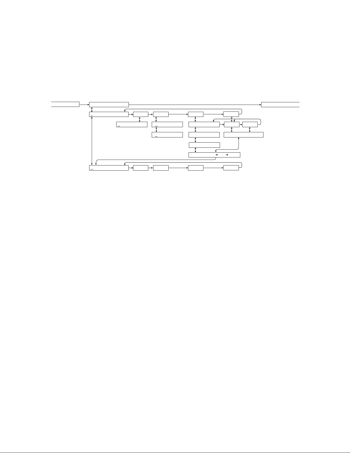
DATA LOGGER MENU (Optional)
Ultrason
PASSWORD: 00 UNITS / MODE
Session No 1
StartJan 01/2000
Start 03:02:16
Isnterval: 24 Hr
Interval: 12 Hrs
Interval: 8 Hrs
Interval: 4 Hrs
Isnterval: 1 Hr
DATA LOGGING
RUN STOP Setup
Log Site ID 1
Formatted Trend
Time Event
StartJan 01/2000
Start 03:02:16
Interval: 30 Sec
Interval: 10 Sec
Interval: 5 Sec
Interval: 2 Sec
Interval: 1 Sec
Interval: 30 Min
Interval: 10 Min
Interval: 5 Min
Interval: 2 Min
Interval: 1 Min
HiAlm LoAlm
At: 5.0 ft3/s
WrapAround? Yes
Reset Log? Yes
26640 Hrs Left
Store? Yes
*** STORING ***
Page 33

AquaMetrix
Ultrason
DATA LOGGING (Optional)
Setup
From
RUN STOP SETUP press Æ to SETUP and then È to Log Site ID 0. Press Æ to position the
cursor under the numeral and È or Ç to change the numerals. The “Site ID” number is retained with
data logging sessions to identify logs stored from different locations.
Formatted Data
Press È from
Formatted” data stores a summary of flow readings over a user-selectable time period. The
“
Log Site ID and press È from Formatted .
summary includes:
DATE and TIME
Interval TOTAL
Interval AVERAGE
Interval MAX FLOW
Interval MAX FLOW TIME
Interval MIN FLOW
Interval MIN FLOW TIME
From
Formatted press È to Start MMM DD/YYYY (eg: Jan 01/2000). Press Æ to position the
cursor and then È or Ç to set the Month, Day and Year that logging will Start. Press Æ to return to
Start.
Press È to
clock in Hours/minutes/seconds, eg:
Æ to return to
Start (time) and Æ to position the cursor under the time column HH/MM/SS (24 hour
23:02:16) and then È or Ç to set the logging start Time. Press
Start .
Press È to
Interval and Æ to the Hrs column. Press È or Ç to select the flow logging interval.
Choose from:
24 Hrs,or 12 Hrs,or 8 Hrs,or 4 Hrs,or 1 Hrs
Press Æ to return to Interval. Press È and the Ultrason will report xxxxx Hrs Left indicating
the amount of logging time available with your current set-up. You can also press Ç to return to
previous menu items and make changes.
Press È to
WrapAround mode the oldest
WrapAround Yes?. Press Æto Yes? and È to enable the logging wrap function. In
data will be overwritten by the newest. If WrapAround is not enabled the
logger will stop when its memory becomes full.
Press È to
sessions and stored values. Or press È from
Ultrason will display “
Reset Log? Yes. Press Æ to Yes and then È to reset the Log and erase all previous
Reset Log? to retain existing data in the Log. The
xxxxx Hrs/Days Left.
Page 34

AquaMetrix
Ultrason
From the xxxxx Hrs Left display press È to Store? Yes. Press Æ to Yes and then È to save
your Data Logging setup, or press È from
Store? to cancel changes made above and exit without
storing changes.
From the Data Logging
position the cursor under
and Time. The Ultrason will display
Store? Yes prompt the menu will return to RUN STOP SETUP. Press Æ to
RUN and press È to activate the Data Logger to start at your selected start Date
SESSION NO. x. Press È to return to DATA LOGGING.
Viewing FORMATTED Data Logs on the Ultrason Display
24 Hour Formatted logs can be viewed directly on the Ultrason display. From
LOG
. This function is available only if 24 Hour Formatted logging has been Stored from the DATA
RUN press Æ to 24 HR
LOGGING menu.
The 24 Hour Log Report is designed to be read one line at time using the Æ key. Using the È or Ç
keys will return the display to the Date column.
TODAYS DATE DAILY TOTAL DAILY AVERAGE MAX FLOW MAX FLOW TIME MIN FLOW MIN FLOW TIME
PREVIOUS DATE “ “ ““““
PREVIOUS DATE “ “ ““““
PREVIOUS DATE “ “ ““““
PREVIOUS DATE “ “ ““““
PREVIOUS DATE “ “ ““““
The current day plus the past 255 days of data can be displayed. (Logger software will display up to
1300 days of data.)
Trend Data Logging - Setup
From
RUN STOP SETUP press Æ to SETUP and then È to Log Site ID 0. Press Æ to position the
cursor under the numeral and È or Ç to change the numerals. The “Site ID” number is retained with
data logging sessions to identify logs stored from different locations.
From
Log Site ID press È to Formatted Trend and press Æ to position the cursor under
Trend. Then press È to select Time based logging.
‘Time’ based Trend Logging
Time based logging allows you to choose Start and Stop times and a logging interval.
From
Time press È to Start MMM DD/YYYY (eg: Jan 01/2000). Press Æ to position the cursor
and then È or Ç to set the Month, Day and Year that logging will Start. Press Æ to return to
Start.
Page 35

AquaMetrix
Ultrason
Press È to Start (time) and Æ to position the cursor under the time column HH/MM/SS (24 hour
clock in Hours/minutes/seconds, eg:
Æ to return to
Start .
23:02:16) and then È or Ç to set the logging start Time. Press
Press È to Interval and Æ to the
Sec/Min column. Press È or Ç to set the logging time interval.
Choose:
30 Sec
10 Sec
5 Sec
2 Sec
1 Sec
30 Min
10 Min
5 Min
2 Min
1 Min
Press Æ to return to to Interval and È to Reset Log? To erase all existing data in the log press Æ
to
Yes and È. To keep existing data in the Log press È from Reset Log? If you have made changes
to the Start Date, Time or Interval, the data logger will automatically start a new “session”. The Ultrason
will display “
From the
Data Logging setup, or press È from
xxxxx Hrs/Days Left”.
xxxxx Hrs Left display press È to Store? Yes. Press Æ to Yes and then È to save your
Store? to cancel changes made above and exit without storing
changes.
From the Data Logging
position the cursor under
and Time. The Ultrason will display
Store? Yes prompt the menu will return to RUN STOP SETUP. Press Æ to
RUN and press È to activate the Data Logger to start at your selected start Date
SESSION NO. x. Press È to return to DATA LOGGING.
‘Event’ based Trend Logging
Event based logging stores data points only when a High or Low flow set point has been reached.
With cursor under
rate, while
LoAlm and press È to the At: prompt. Press Æ to the numerals column and press È or Ç to set flow
LoAlm will log points below a selectable flow rate. Position the cursor under HiAlm or
alarm logging set point. Press Æ to return to
Event press È to HiAlm LoAlm . HiAlm will log points above a selectable flow
At:
Page 36

AquaMetrix
Ultrason
Press È to Interval and Æ to the Sec/Min column. Press È or Ç to set the logging time interval.
Choose:
30 Sec
10 Sec
5 Sec
2 Sec
1 Sec
30 Min
10 Min
5 Min
2 Min
1 Min
Press Æ to return to Interval and press È to Reset Log? To erase all existing data in the log press
Æ to
Yes and È. To keep existing data in the Log press È from Reset Log? If you have made
changes to the Start Date, Time or Interval, the data logger will automatically start a new “session”. The
Ultrason will display “
xxxxx Hrs/Days Left”.
From the
your Data Logging setup, or press È from
xxxxx Hrs Left display press È to Store? Yes. Press Æ to Yes and then È to save
Store? to cancel changes made above and exit without
storing changes.
From the Data Logging
position the cursor under
display
SESSION NO. x. Press È to return to DATA LOGGING.
Store? Yes prompt the menu will return to RUN STOP SETUP. Press Æ to
RUN and press È to activate the Data Logger to start. The Ultrason will
Logging "Sessions"
Each time you select
memory as a "
selecting
NO xx
". When you download the logger files to your PC using AquaMetrix Logger software, each
SESSION NO" automatically numbered from "1"to"10". If you resume logging by
RUN, the Data Logger will report that a new logging session is started and titled "SESSION
STOP in the DATA LOGGING menu, the Data Logger stores the current data in
Session will open as a separate graph/table titled "AquaMetrix Data Log xx".
Important:
If you
STORE instrument calibration changes under the UNITS/MODE or CALIBRATON menus, STOP
the data logger and select RUN again to start a new logging Session with your new calibration values.
Page 37

AquaMetrix
PublicTeleph
RS232C SERIAL OUTPUT (with optional Data Logger)
Ultrason
Format: 8 Bits, 1 Stop Bit, No Parity. (Baud rate may be changed under the
SPECIAL FUNCTIONS
menu. Factory default is 19200 baud).
Output Connector is DB9-Female. Use the cable supplied for connection to a PC Computer. Use the
cable plus the “NULL MODEM” (supplied) for connection to modem.
oneLines
Modem
Computer
AquaMetrix
Ultrason
INCLUDED
RS232
20' (6 m) cable
included
Detail
GND
RX
PU
RS 232
(BLK)
(WHT)
(GREEN)
TX
(RED)
DB9F
ADAPTOR
9M
B
D
DB25F
6
7
8
9
Detail
L
L
U
N
DB25M
1
2
3
4
5
M
E
D
O
DB25M
M
Wired as DCE
(Data Communication Equipment)
PIN2-RX
PIN3-TX
PIN 4 - DTR (PU)
PIN 5 - GND
SHIELD - CASE
(PU = PULL-UP)
Modem
DB25F
DB25M
Computer
DB9M
Page 38

AquaMetrix
Ultrason
RS485 SERIAL OUTPUT
(Replaces standard RS232 Output with Data Logger option.)
Permits transfer of optional Data Logger reports on long wire lengths up to 4000 ft. (1220 m). Use for
Ultrason to PC communication only (not for multidrop RS485 networking).
Format: 8 Bits, 1 Stop Bit, No Parity. (Baud rate may be changed under the
SPECIAL FUNCTIONS
menu. Factory default is 19200 baud).
Use shielded, 4-conductor cable (cable option SC-18AWG recommended). Connect the cable shield to
Ground at the Ultrason electronics enclosure and do not connect to Ground at the other end.
AMqua etrix
Transmitter
with
RS485 Output
RS485
18AWG, 4-conductor, shielded
<4000 ft (1220 m)
Option: SC-18AWG
Detail
GND
RX
PU
TX
RS485
(BLK)
(RED)
(WHT)
(GREEN)
RS232/485 Converter
Option: 485OICR-12V
TX
RX
PU
GND
RS485
RS232
DB25F
RS232 Cable
Option: DB25M/DB9F
DB25M
6ft(2m)
DB9F
Configure the Logger software program for RS485 communications. Under the Communications /
Connection Setup menu, select 'Connected to a 485OICR-12V adaptor.
485OICR-12V
RS232/RS485 Converter
Use with optional RS485 putput for connection to a PC computer
or modem.
•
Optically isolates and protects your computer's RS232 port
•
Terminal block for RS485 connections
•
Operates from 2400 up to19.2K baud
DB25M/DB9F - RS232 Cable
Connects RS232/485 Converter to a PC
Cable length 6 ft.(2 m) with DB25M and DB9F connectors.
Page 39

AquaMetrix
m
ENCLOSURE SUNSCREEN - OPTION SSM
Note:
Ultrason
11" / 280 mm
Exposure to direct sunlight can cause
overheating and moisture condensation
which will reduce the operating life of
electronics.
Protect Instruments from direct sunlight
with this iridite finished aluminum sun
screen (AquaMetrix Option SSM).
Seal conduit entries with caulking
compound to further reduce moisture
condensation.
SENSOR SUNSCREEN - OPTION SSP
11"
280 mm
5"
127 m
Page 40

AquaMetrix
APPENDIX B - APPLICATIONS BACKGROUND
Conditions in the tank or channel where the ultrasonic sensor is installed can affect the performance,
range and accuracy of the system. The following notes are for general reference. Contact AquaMetrix or
your local representative for specific information on your application.
Ultrason
FOAM
ultrasonic level measuring system. Foam acts as a sound insulator and may eliminate, or reduce the
strength of an echo. Measurement range may be reduced in a system where foam is present. Ultrasonics
are not recommended where thick dense foam is continually present. Intermittent or thin layers of light
foam (1/8 in. or less) can generally be disregarded. Use a stilling well in open channel applications.
LIQUIDS
viscous liquids can be monitored without contacting the liquid.
SOLIDS - The Ultrason will measure most granular material and powders as well as liquids. Powders
will not generally provide the same echo strength as liquids. Therefore maximum expected range should
be reduced to approximately 20 feet (6 m) for powders. There are many exceptions to this rule and
installation of a test system is recommended when in doubt.
DUST
concentrations of dust are expected ultrasonics may not work. Where moderate dust is encountered
care should be taken to mount the sensor in a position where dust accumulation will be minimized and
where the sensor can be cleaned if necessary.
SENSOR TEMPERATURE - The standard sensor model US2 supplied with each Level & Flow
Monitor includes a built-in temperature sensor. The Ultrason automatically compensates for temperature
fluctuations to retain high accuracy. Note the operating temperature ranges listed in the product
specifications section. Do not exceed the sensor temperature ratings or damage may occur.
- Solid or dense surfaces such as a smooth liquid surface will give the best echos in an
- The Ultrason is ideal to monitor tank liquid level or inventory. Caustic, corrosive or very
- Any obstructions to the sound will affect performance of the system. In silo’s where heavy
ELECTRONICS TEMPERATURE
specifications. Temperatures higher than the maximum shown can reduce the operating life of the
electronics. Moisture condensation from those temperatures below the range shown can also damage
electronics components. In cold or outdoor environments the optional factory-installed enclosure heater
and thermostat is recommended.
NOISE
vibration will not affect the system. Sensors installed in close proximity to one another in the same tank
may “cross-talk” and should be synchronized.
VAPOUR
can cause false echoes. Variable vapour cannot be compensated.
CHEMICAL COMPATIBILITY
compatabilities. Tank contents should be checked for their compatibility with PVC. An all-teflon
sensor is available for corrosive applications.
- Because the Ultrason’s sensor operates at high sound frequency, regular process noise or
- May affect but it can be compensated for by calibration in-situ. Severe vapour stratification
- Note operating temperature ranges listed in the product
- The Ultrason is constructed of very durable materials with broad
Page 41

AquaMetrix
FROM TO MULTIPLY BY
US GALLONS CUBIC FEET 0.1337
US GALLONS IMPERIAL GALS 0.8327
US GALLONS LITRES 3.785
US GALLONS CUBIC METERS 0.003785
LITRES/SEC GPM 15.85
LITRES CUBIC METERS 0.001
BARRELS US GALLONS 42
BARRELS IMPERIAL GALS 34.9726
BARRELS LITRES 158.9886
INCHES MM 25.4
DEGREES F DEGREES C
POUNDS KILOGRAMS 0.453
PSI BAR 0.0676
FOOT² METER² 0.0929
Ultrason
CONVERSION
GUIDE
(°F-32) x 0.556
VOLUME CALCULATION FOR ROUND TANKS: 3.142 x R² x H
R = TANK RADIUS (1/2 TANK DIAMETER)
H = TANK HEIGHT
Page 42

AquaMetrix
U
Ultrason
SPECIFICATIONS
7.4 / 188 mm"
6.46 / 164 mm"
5.12 / 130 mm"
Electronics Enclosure: NEMA4X (IP 66), watertight
and dust tight, fiberglass with
clear, shatterproof
hinged Lexan cover
Accuracy: 0.25% F.S., Repeatability:
0.1% F.S., Linearity:
0.1%F.S.
Display: Flow/Level Values: ¾” / 19
AMqua etrix
Ultrason
10 / 254 mm"
10.94"/278mm
mm high, 4 digit LCD
Menu/Status/Totalizer:
16 digit LCD alphanumeric
Programming: 3-button keypad with Menu
selection. Calibration
CONDUIT ENTRY
LOCATION
SIDE VIEW
ENCLOSURE
parameters are permanent
when Stored (even through
power interruptions)
Power Input: 100-130VAC 50/60 Hz, (7.2 W max.)
Optional: 200-260VAC 50/60 Hz,(7.2 W max.)
Optional: 12VDC, or 24VDC (6.5 W max)
Output: Isolated 4-20mA, 1000 ohm
load maximum
Control Relay: Qty 3, rated 5 ampere SPDT
Temperature Compensation: Automatic, temperature probe built in to level Sensor
Lightning/Surge Protection: Sensor, 4-20mA, AC power input
Operating Temperature (electronics): -5 to 140°F (-20 to 60°C). Optional Enclosure Heater recommended for
condensation protection below 32°F (-1°C)
Standard Sensor US2-1-A-1-A
Maximum Range: 32 ft. (10 m)
Deadband (blanking): Programmable, minimum 12” (305 mm)
Beam Angle: 8° at3DB
Temperature Compensation: Automatic, continuous
Operating Frequency: 42 KHz
Exposed Materials: PVC and Teflon
Operating Temperature: -40° to 150°F (-40° to 65°C)
Operating Pressure: 20 psi (1.35 Bar) maximum
Hazardous Rating: with optional Intrinsic Safety Barrier: CSA,
Mounting: ¾” NPT (PVC isolation coupling supplied)
Sensor Cable: RG62AU coaxial, 25 ft. (7.6 m) standard
Class I,II,III, Div. I,II, Groups C,D,E,F,G
Note: Max Range reduced to 25 ft (7.6 m) with
ISB option.
Page 43
3/4"
NPT
ISOLATION
COUPLING
(SUPPLIED)
3/4"
NPT
SIDE
VIEW
END
VIEW
PVC
PVC
1-3/4 "
44.5mm
L
TEFLON
O
TEF
25' (7.6 m) RG62A
COAXIAL CABLE
3-7/8 "
98mm
(127 mm)
OVERALL
5"

AquaMetrix
Optional Sensor US2-1-B-1-A
Ultrason
Maximum Range: 32 ft. (10 m)
Deadband (blanking): Programmable, minimum 12” (305 mm)
Beam Angle: 8° at 3 DB
Temperature Compensation: Automatic, continuous
Operating Frequency: 42 KHz
Exposed Materials: Teflon
Operating Temperature: -40° to 170°F (-40° to 76°C)
Operating Pressure: 20 psi (1.35 Bar) maximum
Mounting: ¾” NPT (Teflon isolation coupling
supplied)
Sensor Cable: RG62AU coaxial, 25 ft. (7.6 m) standard
Hazardous Rating: with optional Intrinsic Safety Barrier:
CSA, Class I,II,III, Div. I,II, Groups
C,D,E,F,G,
Note: Max Range reduced to 25 ft (7.6
m) with ISB option.
3/4"
NPT
TEFLON
ISOLATION
COUPLING
(SUPPLIED)
3/4"
NPT
SIDE
VIEW
END
VIEW
TEFLON
TEFLON
1-3/4 "
44.5mm
L
TEFLON
O
T
EF
25' (7.6 m) RG62AU
COAXIAL CABLE
3-7/8 "
98mm
5"
(127 mm)
OVERALL
Optional US2-2-A-1-B
Maximum Range: 50 ft. (15.6 m)
Deadband (blanking): Programmable, minimum 16"(406mm)
Beam Angle: 8º at 3 DB
Temperature Compensation: Automatic, continuous
Operating Frequency: 40 KHz
Exposed Materials: PVC and Teflon
Operating Temperature: -40 to 150ºF (-40 to 65ºC)
Operating Pressure: 20 psi (1.35 Bar) maximum
Sensor Cable: RG62Au coaxial, 50 ft. (15 m) standard
Hazardous Rating: with optional Intrinsic Safety Barrier:
PVC
Mounting: ¾” NPT (Isolation Coupling supplied)
PVC
CSA, Class I,II,III, Div. I,II, Groups
C,D,E,F,G,
Note: Max Range reduced to 32 ft (10
m) with ISB option.
Page 44

AquaMetrix
Optional US12-1-A-1-A
Maximum Range: 12 ft (3.66 m)
Minimum Range (Deadband): 8" (203.2 mm)
Operating Frequency: 92 KHz
Beam Angle: 8°
Operating Temperature: -40° to 150° (-40° to 65°C)
Temperature Compensation: Automatic, continuous
Max. Operating Pressure: 20 psi (1.35 bar)
Sensor Face: PVC
Sensor Body: PVC
Mounting: ¾" NPT
Cable Length: 25 ft. (7.6 m) continuous
RG62AU coaxial. Optional 50
ft. (15 m) continuous
Max. Cable Length: 500 ft. (152 m) RG62AU
coaxial (splice)
Hazardous Rating: CSA rated Intrinsically Safe
Class I, Groups C,D, Class II,
Groups E,F,G with Optional
Intrinsic Safety Barrier.
~3.9"
(99 mm)
OVERALL
2.75"
70 mm
25 ft (7.6 m) RG62AU
COAXIAL CABLE
(50 ft 15 m OPTIONAL)
3/4“ NPT
3/4" NPT
2.75" (70 mm)
Ultrason
ISOLATION
COUPLING
(SUPPLIED)
1"
(25.4 mm)
Optional US12T_F
Maximum Range: 12 ft (3.66 m)
Minimum Range (Deadband): 8"(203.2 mm)
Operating Frequency: 92 KHz
Beam Angle: 8°
Operating Temperature: -40° to 150° (-40° to 65°C)
Temperature Compensation: Automatic, continuous
Max. Operating Pressure: 20 psi (1.35 bar)
Sensor Face: Teflon
Sensor Body: PVC
Mounting: ¾" NPT
Cable Length: 25 ft. (7.6 m) continuous RG62AU coaxial. Optional 50 ft. (15 m)
continuous
Max. Cable Length: 500 ft. (152 m) RG62AU coaxial (splice)
Hazardous Rating: CSA rated Intrinsically Safe Class I, Groups C,D, Class II, Groups E,F,G
with optional Intrinsic Safety Barrier.
25 ft (7.6 m) RG62AU
COAXIAL CABLE
(50 ft 15 m OPTIONAL)
3/4“ NPT
ISOLATION
COUPLING
(SUPPLIED)
~ 4.5"
(114 mm)
OVERALL
82.5 mm
3.25"
3/4 " NPT
TEFLON FACE 0.01" / 0.25mm
BOLT CIRCLE DIAMETER
FLANGE DIAMETER
Page 45
1"
(25.4 mm)

AquaMetrix
CALIBRATION WORKSHEET - Level Mode
for Horizontal Round Tanks (HRT) and Vertical Tanks
(Ultrason reads) A = ______________
Ultrason
Program Ultrason to show RANGE via:
CALIBRATION
MODE
RANGE
LINEAR
STORE
RUN
(DIP STICK) B = ____________
MIN RANGE
MUST BE
12 in (305 mm)
OR MORE
A
C
B
(INSIDE DIA.) C = ____________
A + B = MAX RANGE
___ + ___ = ___________
A+B-C =MINRANGE
___ + ___ - ___ = ___________
Program MIN RANGE then
Use
VOLUME
for Vertical
Tanks
MAX RANGE via:
CALIBRATION
MODE
LEVEL
HRT
MAX. VOL
MIN RG
MAX RG
STORE
RUN
Page 46

AquaMetrix
n
P
CALIBRATION WORKSHEET - Flow Mode
for Open Channel Flow through Flume and Weirs
MAX RANGE
(Ultrason READS)
rogramUltrason to show
RANGE via:
A=______________
SENSOR
Ultrason
MIN RANGE
MUST BE
12 in. (305 mm)
OR MORE
UNITS
SELECTION
ftinmcm%
RANGE
STORE? YES
MAX HEAD
(Height at MAX Flow)
B=______________
A
B
Program MIN RANGE the
MAX RANGE via:
CALIBRATION
MODE
A - B = MIN RANGE
______ - ______ = __________
MIN RANGE
MAX RANGE
STORE? YES
Page 47

V 2.26
SLT32
SPECIAL FUNCTION
1234567890123456
Tag 01
VYiew Codes? es
23:39:51
Date May 31/1999
Time
30 s
LOE Time
Yes
Tot?
Reset
Cº
20.3
Temp
Cº
20.0
Min Temp
Cº
23.0
Max Temp
DISPLAY FCºº
ISB?: No Yes
0.00%
Simul
4.000
4mA ADJ
20.000
20mA ADJ
Yes
Store?
New Password: 00
Com 24 48 96 192
HiAlm
Flow
LoAlm
Level
R1 Mode Pump
R1on 0.00 C°
Temp
Pulse
R1on 0.00 ft3
RELAY PARAMETERS
R1 Function Off
32.00 ft
1.333 ft
CALIBRATION
MinRg
MaxRg
R1 on 0.00ft3/s
R1 OFF 0.00 ft
R1 on 0.00 ft
° C
OFF
R1 0.00
0.00 %
100.00 %
@
20mA @
4mA
Hold
On
R1 LOE Off
%
08 s
20
RejTime
Damping
Flow
Level
Temp
Pulse
R2 Function Off
Yes
Store?
HiAlm
LoAlm
R1 Mode Pump
R1on 0.00 C°
R1on 0.00 ft3
R1 on 0.00ft3/s
R1 OFF 0.00 ft
R1 on 0.00 ft
° C
OFF
R1 0.00
Hold
On
R1 LOE Off
Flow
Level
Temp
Pulse
Function Off
R3
HiAlm
LoAlm
R1 Mode Pump
R1on 0.00 C°
R1on 0.00 ft3
R1 on 0.00ft3/s
R1 OFF 0.00 ft
R1 on 0.00 ft
° C
OFF
R1 0.00
Hold
On
R1 LOE Off
(123456)
ALT
Yes
Store?
SENSOR
MIN
OPTIONAL FEATURES
RANGE
MAX LEVEL
MAX
RANGE
ZERO LEVEL
K=
Custom
More
Sizes
Parshall
FLOW MODE ONLY
Ultrason - CALIBRATION RECORD
FLUME SELECTION
V-Notch
cm %
m
in
UNITS / MODE
ft
PASSWORD: 00
Sizes
Vol Hrt Flow
Level
Range
n=
Yes
Store?
L
USMG
m3
VSG
IMG
IG
ft3
L
USG IG m3
Mx Vol xxxx.x ft3
ft3
123456
LoAlm
5.0 ft3/s
HiAlm
At:
Event
1
Time
Trend
Formatted
StartJan 01/2000
Flow
MAX
AVERAGE
TOTAL
Daily
Daily
Daily
TIME
Flow
MAX
Flow
MIN
Daily
StartJan 01/2000
03:02:16
Start
TIME
Flow
MIN
Log Site ID
Setup
s min hr d
Yes
Store?
DATA LOGGING
24 HR LOG
ONLY IF ENABLED
SHOWS 24 Hr FORMAT
STOP
RUN
1
Session No
->
01/2000
Jan
03:02:16
Start
Interval: 30 Sec
Isnterval: 24 Hr
Interval: 12 Hrs
->
31/1999
Days
Dec
255
5Sec
Interval: 10 Sec
Interval:
-
data
more
no
-
2Sec
1Sec
Interval:
Interval:
Interval: 30 Min
s
Hr
Interval: 8
5 Min
2Min
Interval: 10 Min
Interval:
Interval:
s
Hr
4
Interval:
1 Min
Interval:
Hr
Isnterval: 1
WrapAround? Yes
Yes
Reset Log?
26640 Hrs Left
Yes
*** STORING ***
Store?
RUN
FLOW MODE ONLY
C
RELAYS:
Tot:
E
 Loading...