

Page 1

PM51
Pocket Multimeter
Users Manual
• Mode d’emploi
• Bedienungshandbuch
• Manual d’Uso
• Manual de uso
PN 2153024
August 2004
2004 Meterman Test Tools.
All rights reserved. Printed in Taiwan
Page 2
SELECT
1
4
2
S
E
L
E
C
T
3
5
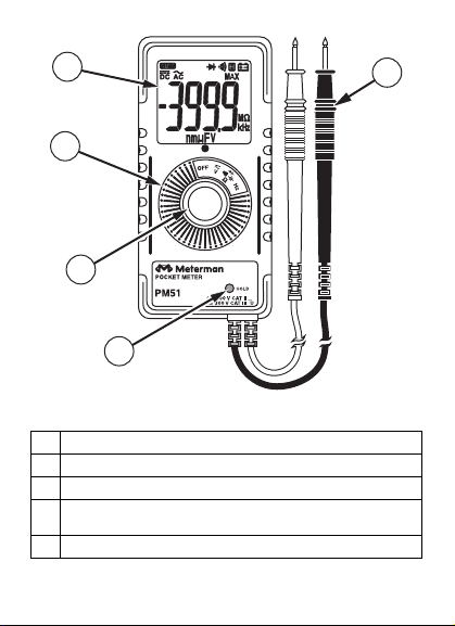
A LCD display
B Rotary switch to select functions and to turn the power on or off
C SELECT-button to select alternate functions.
D Permanently attached red test lead for positive (+) polarity and
black test lead for ground reference (-)
E HOLD button to freeze the display for later viewing.
Page 3

PM51 Pocket Meter
Contents
Introduction ....................................................................................................2
Safety Information...........................................................................................2
Symbols Used in this Manual........................................................................3
Making Measurements ....................................................................................3
Selecting Functions......................................................................................4
V dc and V ac Functions...............................................................................4
Resistance, Continuity, Diode, and Capacitance Functions.............................4
Frequency Function......................................................................................5
Additional Features.......................................................................................6
Product Maintenance.......................................................................................6
Maintenance.................................................................................................6
Cleaning.......................................................................................................6
Troubleshooting...........................................................................................6
Battery Replacement.....................................................................................6
Limited Warranty and Limitation of Liability .....................................................7
Repair.............................................................................................................8
Specifications..................................................................................................9
1
Page 4

Introduction
The PM51 meter is a shirt-pocket size meter only 19 mm (.75 in) wide and
weighing less than 85 g (3 oz). With full functionality offering AC and DC
voltage to 600 V, resistance to 40 MΩ, capacitance to 300 µF, frequency to
1 MHz, continuity with beeper, and diode test. Fully autoranging, the PM51
offers seven different measurement functions with 27 full ranges of
measurement. The digital display is oversized with large digits and icons in
the display. In spite of its small size, the PM51 is full safety rated to CAT III
300 V, CAT II 600 V, and is UL listed. No other meter offers this size with
such performance and high safety ratings.
Safety Information
• The PM51 Digital Multimeter is certified for cULus and EN61010-
1:2001; CAT II 600 V, CAT III 300 V, class 2 and pollution deg. 2.
• This instrument is EN61010-1 certified for Installation Category II
(600 V). It may only be used to make measurements on energy limited
circuits within equipment and not directly connected to mains.
• This instrument is EN61010-1 certified for Installation Category III
(300 V). It is recommended for use with local level power distribution,
appliances, portable equipment, etc., where only smaller transient
overvoltages may occur, and not for primary supply lines, overhead
lines and cable systems.
• Do not exceed the maximum overload limits per function (see
specifications) nor the limits marked on the instrument itself. Never
apply more than 600 V between the test lead and earth ground.
• Inspect the DMM, test leads and accessories before every use. Do not
use any damaged part.
• Never ground yourself when taking measurements. Do not touch
exposed circuit elements or test probe tips.
• Do not operate the instrument in an explosive atmosphere.
• Exercise extreme caution when: measuring voltage >20 V // current >10
mA // AC power line with inductive loads // AC power line during
electrical storms // current, when the fuse blows in a circuit with open
circuit voltage > 600 V // servicing CRT equipment.
• Remove test leads from circuit before opening the case.
2
Page 5

Symbols Used in this Manual
N Battery W Refer to the manual
T Double insulated X Dangerous Voltage
F Direct Current J Earth Ground
B Alternating Current R Audible tone
Complies with EU
P
directives
Making Measurements
All measurements described in this manual use the red test lead for positive
(+) polarity and the black test lead for ground reference (-) unless otherwise
specified.
Power On and Off
Turn the rotary switch to turn the power ON or OFF.
Underwriter Laboratories,
>
Inc.
3
Page 6

Selecting Functions
Select measurement as shown in the diagram on the back of the meter.
V dc and V ac Functions
Rotate the rotary selector to the V position. V dc is the default function. The
dc annunciator F appears on the display. Press the SELECT button
momentarily to select V ac. The ac annunciator B appears on the display.
Resistance, Continuity, Diode, and Capacitance
Functions
• Turn the rotary switch to the Ω/R/G/ position. Resistance is the
default function.
1. Turn off power to the circuit being measured. Never measure resistance
across a voltage source or on a powered circuit.
2. Discharge any capacitors that may influence the reading.
3. Connect the test probes across the resistance.
4. Read the display. If OL appears on the highest range, the resistance is
too large to be measured or the circuit is an open circuit.
4
Page 7

• A continuous beep tone indicates a complete circuit.
1. Turn off power to the circuit being measured.
2. Discharge any capacitors that may influence the reading.
3. Connect the test probes across the resistance or two measurement
nodes.
4. Listen for the tone that indicates continuity (< 120 Ω).
• Press the SELECT button momentarily AGAIN to select Diode test
function. The annunciator G appears on the display. The reading
shows the approximate voltage drop across the test leads. Normal
forward voltage drop (forward biased) for a good silicon diode is
between 0.400 V to 0.900 V. A reading higher than that indicates a leaky
diode (defective). A zero reading indicates a shorted diode (defective).
OL indicates an open diode (defective). Reverse the test leads
connections (reverse biased) across the diode. The digital display shows
OL if the diode is good. Any other readings indicate the diode is
defective.
• Press the SELECT button momentarily AGAIN to select the Capacitance
function.
1. Turn off power to the circuit being measured.
2. Discharge the capacitor using a 100 kW resistor.
3. Free at least one end of the capacitor from the circuit.
4. Connect the test probes across the capacitor.
5. Read the display.
Frequency Function
Turn the rotary switch to the Hz position to select the frequency function.
This function is set only at the highest input sensitivity mainly for
measuring small electronic signals below 20 V ac rms.
1. Connect the test probes to the signal source.
2. Read the display.
5
Page 8

Additional Features
HOLD and 30 ms MAX HOLD Modes
HOLD mode freezes the display for later viewing. Press the HOLD button
momentarily to activate or to exit the Hold feature.
MAX mode captures voltage signals that have durations as short as 30 ms
(milliseconds) within a single range, and has automatic up range capability.
This feature is available in V dc and V ac functions. Press the HOLD button
for 1 second or more to activate or exit MAX mode.
Hazardous voltages present at test leads may not be
displayed when in HOLD mode.
Auto-ranging
If the function selected has more than one range, the meter will auto-range
to the best range and resolution.
XWWARNING
Product Maintenance
Maintenance
Do not attempt to repair this meter. It contains no user serviceable parts.
Repair or servicing should only be performed by qualified personnel.
Cleaning
Periodically wipe the case with a damp cloth and mild detergent; do not use
abrasives or solvents. If the meter is not to be used for periods of longer
than 60 days, remove the battery and store it separately
Troubleshooting
If the instrument fails to operate, check battery, leads, and replace as
necessary. Double check operating procedure as described earlier in this
manual. Refer to the LIMITED WARRANTY section for obtaining warranty or
repairing service.
Battery Replacement
If the meter starts up with persistent resetting display or with low battery
icon N turns on, replace the battery. The meter uses one 3 V coin battery,
IEC-CR2032.
6
Page 9

To replace the battery
1. Turn off the meter and disconnect the test leads from live circuits.
2. Loosen the screw on the case bottom.
3. Lift the end of the case bottom nearest the input test leads until it
unsnaps from the case top. Replace the battery cover and tighten the
screw. Recycle the battery using approved methods.
4. Replace the battery. Observe battery polarities with positive (+) faces up
(towards the case bottom). Replace the case bottom, and ensure that
the snap on the case top (near the LCD side) is engaged.
5. Replace and tighten the screw.
To avoid electrical shock, disconnect test leads from live
circuits before opening the case. Do not operate with open
case.
Limited Warranty and Limitation of Liability
Your Meterman product will be free from defects in material and
workmanship for 1 year from the date of purchase. This warranty does not
cover fuses, disposable batteries or damage from accident, neglect, misuse,
alteration, contamination, or abnormal conditions of operation or handling.
Resellers are not authorized to extend any other warranty on Meterman’s
behalf. To obtain service during the warranty period, return the product with
proof of purchase to an authorized Meterman Test Tools Service Center or
to a Meterman dealer or distributor. See Repair Section for details. THIS
WARRANTY IS YOUR ONLY REMEDY. ALL OTHER WARRANTIES WHETHER EXPRESS, IMPLIED OR STAUTORY - INCLUDING IMPLIED
WARRANTIES OF FITNESS FOR A PARTICULAR PURPOSE OR
MERCHANTABILITY, ARE HEREBY DISCLAIMED. MANUFACTURER SHALL
NOT BE LIABLE FOR ANY SPECIAL, INDIRECT, INCIDENTAL OR
CONSEQUENTIAL DAMAGES OR LOSSES, ARISING FROM ANY CAUSE OR
THEORY. Since some states or countries do not allow the exclusion or
limitation of an implied warranty or of incidental or consequential damages,
this limitation of liability may not apply to you.
XWWARNING
7
Page 10

Repair
All test tools returned for warranty repair or for calibration should be
accompanied by the following: your name, company’s name, address,
telephone number, and proof of purchase. Additionally, please include a
brief description of the problem or the service requested and include the
test leads with the meter. Non-warranty repair or replacement charges
should be remitted in the form of a check, a money order, credit card with
expiration date, or a purchase order made payable to Meterman Test Tools.
In-Warranty Repairs and Replacement – All Countries
Please read the warranty statement, and check your battery before
requesting repair. During the warranty period any defective test tool can be
returned to your Meterman Test Tools distributor for an exchange for the
same or like product. Please check the “Where to Buy” section on
www.metermantesttools.com for a list of distributors near you.
8
Page 11

Specifications
General Specifications
Display and Update Rate: 3-3/4 digits 4000 counts; Updates 3 per second
nominal
Operating Temperature: 0 °C - 40 °C
Relative Humidity: Maximum 80% R.H. up to 31 °C, decreasing linearly to
50% R.H. at 40 °C
Altitude: Operating below 2000 m
Storage Temperature: -20 °C ~ 60 °C, < 80% R.H. (with battery removed)
Temperature Coefficient: Nominal 0.15 x (specified accuracy)/ °C @
(0°C ~ 18 °C or 28 °C ~ 40 °C), or otherwise specified
Sensing: Average sensing
Overload Protection: 600 V dc and V ac rms
Low Battery: Below approx. 2.4 V
Power Supply: 3 V standard button battery x 1
(IEC-CR2032; ANSI-NEDA-5004LC)
Power Consumption (typical): 2 mA
APO Consumption (typical): 2.2 µA
APO Timing: Idle for 30 minutes
Dimension / Weight
L 113 mm x W 53 mm x H 10.2 mm / Approx. 78 gm
Special Features
Data Hold, and 30ms MAX Hold
Agency Approvals
P >
Safety: Meets IEC61010-1, UL61010B-1, CAN/CSA-C22.2 No. 1010.1-92,
CAT II 600 V and CAT III 300 V, Pollution Degree 2, Class 2
9
Page 12

E.M.C. Meets EN61326 (1997, 1998/A1), EN61000- 4-2 (1995), and
EN61000-4-3 (1996). This product complies with requirements of the
following European Community Directives: 89/ 336/ EEC (Electromagnetic
Compatibility) and 73/ 23/ EEC (Low Voltage) as amended by 93/ 68/ EEC
(CE Marking). However, electrical noise or intense electromagnetic fields in
the vicinity of the equipment may disturb the measurement circuit.
Measuring instruments will also respond to unwanted signals that may be
present within the measurement circuit. Users should exercise care and
take appropriate precautions to avoid misleading results when making
measurements in the presence of electronic interference.
Accessories
Battery installed, and User’s manual
Optional Accessories:
H-PM protective holster, and VC3 soft carrying pouch
Electrical Specifications
(Accuracy @ 23 oC +/- 5 oC and < 75% R.H.)
RF Field @ 3 V/m: Specified accuracy + 45 d (Capacitance not specified)
DC Voltage
Range Accuracy
400.0 mV ±(1.0%+2 dgt)
4.000 V, 40.00 V, 400.0 V ±(2.0%+2 dgt)
600 V ±(2.5%+4 dgt)
NMRR: > 50 dB @ 50 Hz/60 Hz
CMRR: > 120 dB @ dc, 50 Hz/60 Hz; Rs=1 kΩ
Input Impedance: 10 MΩ, 30 pF nominal; (1000 MΩ for 400.0 mV
range)
10
Page 13

AC Voltage
Range Accuracy
50 Hz – 60 Hz
4.000 V, 40.00 V, 400.0 V ±(2.0%+5 dgt)
60 Hz – 500 Hz
4.000 V, 40.00 V, 400.0 V ±(3.0%+5 dgt)
50 Hz – 500 Hz
600 V ±(3.5%+5 dgt)
Input Impedance: 10 MΩ, 30 pF nominal
CMRR: > 60 dB @ DC to 60 Hz, Rs=1 kΩ
Capacitance
Range1 Accuracy2
500.0 nF, 5.000 µF, 50.00 µF,
500.0 µF, 3000 µF3
1
Additional 50.00 nF range accuracy is not specified
2
Accuracies with film capacitor or better.
3
Updates > 1 minute on large values
4
Specified with battery voltage above 2.8 V (half full battery). Accuracy
decreases gradually to 12% at low battery warning voltage of approx
2.4 V
±.(3.5%+6 dgt4)
11
Page 14

Ohms
Range Accuracy
400.0 Ω ±(1.5%+6 dgt)
4.000 KΩ, 40.00 KΩ, 400.0 KΩ ±(1.0%+4 dgt)
4.000 MΩ ±(1.5%+4 dgt)
40.00 MΩ ±(2.5%+4 dgt)
Open Circuit Voltage: 0.4 V dc typical
Frequency
Range1 Accuracy
400 Hz, 4 kHz, 40 kHz, 400 kHz,
and 1 MHz
1
Specified at Input Voltage < 20 V ac rms Input Signal: Sine-wave, or
Square-wave with duty cycle > 40% & < 70%
Sensitivity (V-peak):
5 Hz - 100 kHz : > 1.3 Vp
100 kHz - 500 kHz : > 2.2 Vp
500 kHz - 1 MHz : > 4.2 Vp
Diode Tester
Test Current (Typical): .25 mA
Open Circuit Voltage: 1.6 V dc
Audible Continuity Tester
Open Circuit Voltage: 0.4 V dc typical
Audible Threshold: between 10 Ω and 120 Ω
±(0.5%+4 dgt)
12
 Loading...