

Page 1

Operator’s Manual
Model DM73B
Pen Style
Digital Multimeter
•
Bedienungsanleitung
• Manual de Instrucciones
• Manual d’Utilization
Di
gi
ta
l
Page 2

The DM73B Digital Multimeter is warranted against any defects of
material or workmanship within a period of one (1) year following the
date of purchase of the multimeter by the original purchaser or original
user. Any multimeter claimed to be defective during the warranty
period should be returned with proof of purchase to an authorized
Meterman Test Tools Service Center or to the local Meterman Test
Tools dealer or distributor where your multimeter was purchased. See
maintenance section for details. Any implied warranties arising out of
the sale of a Meterman Test Tools multimeter, including but not limited to implied warranties of merchantability and fitness for a particular
purpose, are limited in duration to the above stated one (1) year period. Meterman Test Tools shall not be liable for loss of use of the
multimeter or other incidental or consequential damages, expenses, or
economical loss or for any claim or claims for such damage, expenses
or economical loss. Some states do not allow limitations on how long
implied warranties last or the exclusion or limitation of incidental or
consequential damages, so the above limitations or exclusions may
not apply to you. This warranty gives you specific legal rights, and you
may also have other rights which vary from state to state.
CONTENTS
Warranty 1
Certifications and Precautions 1
Introduction 2
Measuring Procedures 2
Maintenance and Repair 4
Specifications 5
CERTIFICATIONS AND PRECAUTIONS
■ The DM73B instrument is UL, cUL, and EN61010-1 certified for
Installation Category II – 600V. It is recommended for use with local
level power distribution, appliances, portable equipment, etc, where
only smaller transient overvoltages may occur, and not for primary
supply lines, overhead lines and cable systems. ■ Do not exceed the
WARRANTY
1
Page 3
maximum overload limits per function (see specifications) nor the
limits marked on the instrument itself. Never apply more than 600VDC
between the test lead and earth ground.■ Exercise extreme caution
when: measuring voltage >20V // servicing CRT equipment. ■ Inspect
DMM, test leads and accessories before every use. Do not use any
damaged part. ■ Never ground yourself when taking measurements.
Do not touch exposed circuit elements or probe tips. ■ Do not operate
instrument in an explosive atmosphere.
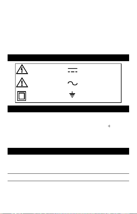
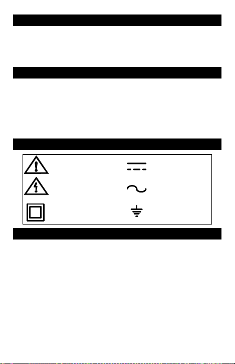
EXPLANATION OF SYMBOLS
DANGER High
Voltage
ATTE NTION
Refer to Manual
This Instrument has
double insulation
Direct Current
Alternating Current
Protective Conductor
Terminal
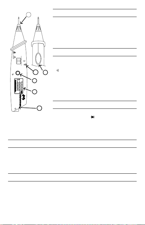
The DM73B is a probe-type digital multimeter capable of measuring
DC and AC voltage, resistance, diode and continuity. Its controls are:
Volts (V), Ohms ( Ω ), Diode Test and Continuity Beeper (
), On- Off,
AC/ DC and Hold. (See page 3) 1. V - Ω input. 2. Function selector.
3. HOLD button. 4. SHIFT button for AC / DC or Diode /Continuity. 5.
LCD Display. 6. COM input.
MEASURING PROCEDURES
When connecting or disconnecting test leads to or from a circuit,
Note:
always first turn off power to the circuit under test and discharge all
capacitors.
DC / AC Voltage Measurement
Set the Function switch to “V”. Select AC or DC by pressing the mode
selector button (AC or DC is displayed). Connect the instrument to the
circuit and read the measured voltage in the display.
INTRODUCTION
2
Page 4
1
V
Ω
OFF V
CAT II
Ω
MAX600V
SHIFT
2
DC
AC
0
4
10 3020
Mk
mV
H S
Ω
5
+
DM73B
DIGITAL
MULTIMETER
COM
mode selector button twice, so that appears (
the instrument across the device to be tested. The forward voltage
drop of a good diode is about 0.6V. An open or reverse biased diode
will read “OL”.
Data Hold
Push the HOLD button to “freeze” the measurement reading and then
remove the test leads while the reading remains displayed. HOLD is
useful when it is necessary to pay very close attention to your work.
Pushing the HOLD button again releases the display.
Automatic Shutdown
This function causes the meter to enter power saving mode after
approximately 10 minutes. Disable automatic shutdown by holding
the shift button down while turning the meter on.
Resistance Measurement
Set the Function switch to “ Ω ”. Connect the
instrument across the resistance and read
the value in the display. When measuring
high resistance values, take care not to touch
the test leads.
Continuity Measurement
H
Set the Function switch to Ω . Press the
mode selector button once, so that appears
) in the LCD. Connect the instrument
(
3
across the device or wire to be tested.
Beeper will sound when continuity is established. The beeper also sounds when changing functions, modes, or for Probe Hold.
Diode Measurement
6
Set the Function switch to Ω . Press the
) in the LCD. Connect
3
Page 5
MAINTENANCE
In Case of Difficulties
first review the operating instructions for possible errors in operation.
Inspect and check test leads for continuity. Check the condition of the
batteries. The battery “
below the level where accuracy is guaranteed. Replace batteries
immediately.
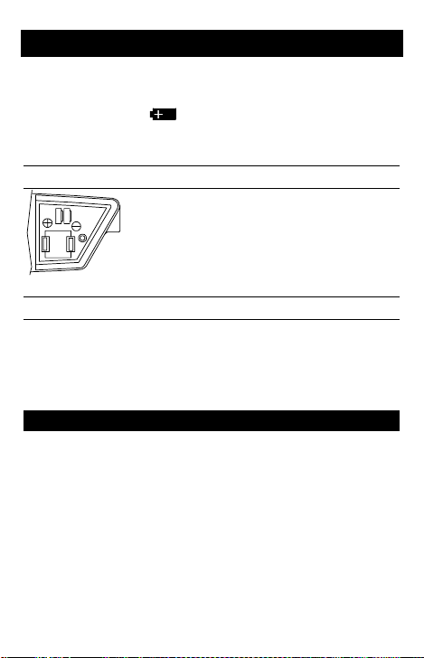
Battery Replacement
Cleaning Procedure
Gently wipe dirt from the surface of the unit with a soft cloth moistened
with a small amount of water or neutral cleanser. Do not use benzene,
alcohol, acetone, ether, paint thinner, lacquer or ketone solvents on
the units, under any circumstances as these may cause deformation
or discoloration.
In the case of improper operation of the meter,
” symbol appears when the voltage falls
Warning:
In order to avoid electrical shock,
remove the test lead before opening the case.
To replace the batteries ( 2 – LR44) unscrew the
battery hatch screw and remove the old batteries.
Install the new batteries observing the diagram in
the battery area.
REPAIR
Read the warranty located at the front of this manual before requesting warranty or non-warranty repairs. For warranty repairs, any multimeter claimed to be defective can be returned to any Meterman Test
Tools authorized distributor or to a Meterman Test Tools Service
Center for an over-the-counter exchange for the same or like product.
Non-warranty repairs should be sent to a Meterman Test Tools Service Center. Please call Meterman Test Tools or enquire at your point
of purchase for the nearest location and current repair rates. All multimeters returned for warranty or non-warranty repair or for calibration
should be accompanied by the following information or items: company name, customer’s name, address, telephone number, proof of
4
Page 6

purchase (warranty repairs), a brief description of the problem or the
service requested, and the appropriate service charge (for nonwarranty repairs). Please include the test leads with the meter. Service
charges should be remitted in the form of a check, a money order,
credit card with expiration date, or a purchase order made payable to
Meterman Test Tools or to the specific service center. For minimum
turn-around time on out-of-warranty repairs please phone in advance
for service charge rates. The multimeter should be shipped with transportation charges prepaid to one of the following addresses or to a
service center:
in U.S.A. in Canada in Europe
Meterman Test Tools Meterman Test Tools Meterman Test Tools
1420 75th Street SW 400 Britannia Rd. E.Unit #1 52 Hurricane Way
Everett, WA 98203 Mississauga, ON L4Z 1X9 Norwich, NR6 6JB, U.K.
Tel: 1-877-596-2680 Tel: (905) 890-7600 Tel: int + 44-1603-404824
Fax: 425-446-6390 Fax: (905) 890-6866 Fax: int + 44-1603-482409
The instrument will be returned with the transportation charges paid by
Meterman Test Tools.
SPECIFICATIONS
General Specifications
Display: 3- 3/ 4 digit LCD, 3400 count
Measuring rate: 2.5/ second nominal
Bargraph: 34 segments – updated 20 readings per second
Operating Temp. range: 0 to 40° C, 80% RH
Storage Temp. range: -20 to 60° C, 70% RH
Environmental: Intended for Indoor use, Altitude up to 2000 m.
Measurement Accuracy: x0.1/ C°
Batteries: 2x LR44, SR44 or S76
Life: 100 hours nominal
Auto Power Off: after 10 minutes
Dimension: 7.8” x 1.1” x 1.4”
Weight: .21 lb.
Accessories: Operating manual, test lead with alligator clip, 2 batteries (installed), spare tip.
Approvals: Safety consideration for UK: do not to measure electrical
5
Page 7
mains supply.
Safety: Conforms to EN61010- 1: Cat II - 600V; CAT III - 300V , Class
2, Pollution degree II; UL3111-1. EMC: Conforms to EN61326
This product complies with requirements of the following European Community Directives: 89/ 336/ EEC
(Electromagnetic Compatibility) and 73/ 23/ EEC (Low
Voltage) as amended by 93/ 68/ EEC (CE Marking). However, electrical noise or intense electromagnetic fields in the vicinity of the equipment may disturb the measurement circuit. Measuring instruments will
also respond to unwanted signals that may be present within the
measurement circuit. Users should exercise care and take appropriate
precautions to avoid misleading results when making measurements
in the presence of electronic interference.
Electrical Specifications
Accuracy at 23°C ± 5°C, < 75 % RH, guaranteed for one year.
DC Volts
Ranges: 340mV, 3.4, 34, 340V, 600V
Accuracy: ± (0.5% rdg + 2 dgt)
Input Impedance: 340 mV range: >100MΩ , other ranges: 10MΩ
Protection: 600VDC or AC rms
AC Volts
Ranges: 3.4V, 34, 340, 600V
Accuracy: ± (1.5 % rdg + 8 dgt) (50 - 500Hz)
Input Impedance: 10MΩ
Protection: 600VDC or AC rms.
Resistance
Ranges: 340 Ω , 3.4, 34, 340 kΩ , 3.4, 34 MΩ
Accuracy:
340Ω - 340kΩ: ± (1.0 % rdg + 4 dgt)
3.4MΩ: ± (1.5 % rdg + 4 dgt)
34 MΩ: ± (3.0 % rdg + 5 dgt)
Max. open circuit voltage: 340Ω range - 1.2V; all others: - 0.45V
Protection: 500VAC or DC.
6
Page 8

Diode Test
Range: 3.4V
Accuracy: ± (2.0%rdg + 3 dgt)
Resolution: 0.1mV in 3.4V range
Short circuit current: 1.0mA
Max open circuit voltage: 3.0VDC
Audible indication: < 0.2V
Overload prot.: 500VDC or AC rms
Continuity
Display response: <0.5s
Continuity threshold: ≤ 3
Overload prot.: 500VDC or AC rms
Accessories / User Replaceable Parts
TL73B Test lead with alligator clip
VC11 Vinyl Case
TP73B Replaceable Probe tip
Battery Type SR44, LR44, or S76
0 Ω
7
Page 9

Bedienungsanleitung
Model DM73B
Digitales Stift-Multimeter
Di
gi
ta
l
Page 10
GEWÄHRLEISTUNG
Das digitale Stift- Multimeter DM73B ist ab Kaufdatum für ein (1) Jahr
gegen Material- und Herstellungsfehler gewährleistet. Siehe “Reparatur” für Einzelheiten. Für weiterführende Ansprüche aus Garantiefällen, wie Folgeschäden, Gewinnausfälle usw. kommt nicht auf.
INHALT
Gewährleistung 9
Warnungen und Sicherheitshinweise 9
Beschreibung 10
Bedienungsanleitung 10
Wartung und Reparatur 11
Spezifikationen 13
ERKLÄRUNG DER SYMBOLE
Achtung! Bitte
Anleitung lesen
Eine gefährliche
Spannung kann den
Eingängen anliegen.
Dieses Gerät ist
doppelt isoliert.
Gleichstrom
Wechselstrom
Erdanschluß
Warnungen und Sicherheitshinweise
Anmerkung: Das Symbol auf der Frontplatte des Gerätes bedeutet:
“Bitte die Bedienungsanleitung folgen.” ■ Dieses Gerät ist UL, cUL,
und EN61010- 1 zertifiziert für Installationsklasse II. Anwendung ist
empfohlen für lokale Stromverteilung, Haushaltgeräte, tragbare
Geräte, usw, wo nur kleinere Spannungsspitzen auftre-ten können,
und nicht für primäre Stromverteilung und Hochspannungsleitungen.
■ Überschreiten Sie nie die kontinuierlichen Überlastgrenzen per
Funktion (siehe Spezifikationen) oder andere Grenzen welche auf
dem Gerät markiert sind. Legen Sie nie mehr als 600V Gleichspannung zwischen Meßkabel und Erde an. ■ Äußerste Vorsicht beim
Messen von: Spannung >20V // beim Messen an Bildröhrgeräten
9
Page 11

(hohe Spannungs- spitzen) ■ Unsersuchen Sie Gerät, Meßkabel,
Verbinder, usw. vor jeder Messung. Beschädigte Teile nicht verwenden ■ Meßspitzen und Stromkreis wäh-rend der Messung nicht
berühren ■ Sich selbst isolieren ! ■ Gerät nicht in explosiver Umgebung verwenden.
Beschreibung
1
V
Ω
OFF
CAT II
V
Ω
MAX600V
SHIFT
2
DC
AC
0
4
10 3020
Mk
mV
H S
Ω
5
+
DM73B
DIGITAL
MULTIMETER
COM
Gleich-/ Wechselspannungsmessung
Stellen Sie den Funktionsschalter auf “V”. Wählen Sie AC oder DC
durch Drücken des Wahlknopfes (AC oder DC erscheint in der Anzeige). Verbinden Sie die Meßspitzen mit dem Schaltkreis und lesen
Sie den Meßwert ab.
Widerstandsmessung
Stellen Sie den Funktionsschalter auf Ω . Verbinden Sie die
Meßspitzen mit dem Widerstand und lesen Sie den Meßwert auf der
Anzeige. Bei hohen Widerständen Meßspitzen nicht berühren.
Das DM73B ist ein digitales Stiftmultimeter
zur Messung von Gleich- und Wechselspannung, Widerstand und Durchgang.
Wahlmöglichkeiten umfassen Spannung (V)
Widerstand (R), Diodentest, Durchgang mit
Summer (
), Ein- Aus, AC/ DC und Hold.
1. V - Ω Eingang. 2. Funktion Schalter. 3.
HOLD tasten. 4. SHIFT tasten für AC / DC
oder Diode /Continuity. 5. LCD Einheitsan-
H
zeigen. 6. COM Eingang.
3
Bedienungsanleitung
Note
Hinweis: Bevor Sie die Meßspitzen mit dem
Schaltkreis verbinden oder davon trennen,
Schaltkreis abschalten und Kondensatoren
entladen. Bei Durchgang ertönt ein
Summton –ebenfalls bei Funktionswechsel,
6
AC/ DC Umschaltung und Probe Hold.
10
Page 12

Durchgangsprüfung
Stellen Sie den Funktionsschalter auf Ω . Drücken Sie einmal den
Wahlknopf, so daß (
das Meßgerät mit dem Schaltkreis.
) auf der LCD Anzeige erscheint. Verbinden Sie
Diodentest
Stellen Sie den Funktionsschalter auf “Ω”. Drüchen Sie zweimal auf
den Wahlknopf bis das (
) auf der LCD Anzeige erscheint. Verbinden Sie das Meβgerät mit dem Schaltkreis. Die Anzeige miβt einen
Spannungsabfall von ungefähr 0.6V bei einer guten Diode. OL als
Meβergebnis deutet auf einen offenen Stromkreis oder eine Sperrichtung.
Anzeigesperre
HOLD Taste drücken um den Meßwert auf der Anzeige festzuhalten.
Der Meßwert bleibt erhalten, auch wenn die Meßspitzen vom
Schaltkreis entfernt sind. HOLD Taste erneut drücken um die Anzeige
freizugeben.
Automatische Abschaltung
Wenn das Gerät 10 Minuten lang nicht benutzt wird, schaltet es automatisch ab. Um diese Abschaltung zu umgehen, drücken Sie beim
Einschalten des Gerätes gleichzeitig den “Shift/ Hold” Knopf.
Wartung
Im Problemfall
zuerst die Meßmethode mit der Gebrauchsanleitung. Prüfen Sie den
Durchgang der Meßkabel. Prüfen Sie die Batterie. Das Symbol “
erscheint in der Anzeige wenn die Spannung unter die Grenze fällt
wobei die Genauigkeit gewährleistet ist. Ersetzen Sie sofort die Batterie.
Sollte das Gerät nicht richtig funktionieren, prüfen Sie
”
11
Page 13

Reinigung des Gerätes
Warnung:
den, entfernen Sie das Meßkabel vor Öffnen des
Gerätes. Reinigen Sie das Gerät mit einem
weichen Tuch und einer milden Seifenlösung
oder einem neutralen Reinigungsmittel. Kein
Benzin, Alkohol, Azeton, Ether oder andere
Lösungsmittel verwenden. Diese Produkte können das Gerät
beschädigen.
Um elektrischen Schock zu vermei-
Batteriewechsel
Batteriedeckel vorsichtig abheben durch Druck unter die Deckellippe
auszuüben. Batterie durch (2 – LR44) unter Beachtung der Polarität
ersetzen. Batteriedeckel wieder anbringen und Gerät wie unten
beschrieben zusammensetzen.
REPARATUR
Lesen Sie die Gewährleistung bevor Sie eine Reparatur unter oder
außerhalb Gewährleistung anfragen. Unter Gewährleistung bringen
Sie bitte das def ekte Gerät zu einer anerkannten Meterman Test
Tools Verkaufsstelle oder Servicestelle füreinen direkten Umtausch.
Außerhalb Gewährleistung senden Sie das Gerät zu einer Meterman
Test Tools anerkannten Servicestelle. Bitte informieren Sie sich bei
Meterman Test Tools oder ihrem Fachhändler nach der dichtst beigelegen Adresse und nach aktuellen Reparaturgebühren. Bitte senden
Sie folgende Informationen und Dokumentemit: Firmenname, Kundenname, Adresse, Telefoonnummer, Kaufnachweis ( für Reparaturen
unter Gewährl eistung), eine kurze Beschreibung der gewünschten
Handlung, und die geforderte Bezahlung ( Eingriffeaußerhalbder
Gewährleistung). Bitteauch Testkabel beifügen. Bezahlungen in Form
eines Checks, Bezahlungsformulieren, Kredietkarte mit Verf alldatum,
usw. bitte in Namen der Servicestelle aufstellen. Bitte Multimeter (Frei)
senden an:
12
Page 14

U.S.A. Canada Europe
Meterman Test Tools Meterman Test Tools Meterman Test Tools
1420 75th Street SW 400 Britannia Rd. E.Unit #1 52 Hurricane Way
Everett, WA 98203 Mississauga, ON L4Z 1X9 Norwich, NR6 6JB, U.K.
Tel: 1-877-596-2680 Tel: (905) 890-7600 Tel: int + 44-1603-404824
Fax: 425-446-6390 Fax: (905) 890-6866 Fax: int + 44-1603-482409
oder an die Ihnen mitgeteilte Adresse. Multimeter wird (Frei) zurück
geschickt.
Allgemein Spezifikationen
Anzeige: 3- 3/ 4 Digit, 3400 Punkte
Meßrate: 2,5/ Sekunde, nominal
Betriebstemperatur: 0 bis 40° C, 80% RF
Lagertemperatur: -20 bis 60° C, 70% RF
Umgebungsdaten: Innen, Höhe 2000m
Genauigkeit: x 0.1/ °C
Batterie: 2x LR44, SR44 oder S76
Autonomie: 100 Stunden, nominal
Automatische Abschaltung: nach 10 MinutenInaktivität
Abmessungen: 198 x 29 x 35 mm
Gewicht (mit Batterie): 100 gr.
Zubehör: Anleitung, Meßkabel, ein Krokodil-klemmen, Batterie, und
Meßspitze
Sichherheit: Gemäß EN61010-1 Cat II – 600V; CAT III-300V;
Verschmutzungsgrad 2; Klasse II; UL3111-1. EMC: Gemäß EN61326.
(Niedrige Spannung) geändert durch 93/ 68/ EEC (CE Marking).
Elektrisches Rauschen und starke magnetische Felder in der direkten
Umgebung des Meßgerätes können jedoch den Meßkreis beeinflussen. Das Gerät kannauch durch Störsignale im gemessenen
Schaltkreis beeinflußt werden. Der Anwender muß Vorsichtsmaßnahmen treffen um irreführende Meßergebnisse bei Messungen in der
SPEZIFIKATIONEN
Dieses Produkt beantwortet an die Bestimmungen der
folgenden EWG Richtlinien: 89/ 336/ EEC
(Elektromagnetische Kompatibilität) und 73/ 23/ EEC
13
Page 15

Umgebung von starken elektromagnetischen Feldern zu vermeiden.
Spezifikationen können ohne vorherige Ansage geändert werden
Elektrische Spezifikationen
Genauigkeiten bei 23°C ± 5°C, < 75 % R.F. nicht kondensierend, für
ein Jahr garantiert
Gleichspannung
Bereiche: 340mV, 3,4V, 34V, 340V, 600V
Genauigkeit,: ± (0,5% vMW ± 2 Dgt)
Eingangsimpedanz: 10MΩ (340mV: >100MΩ)
Überlastschutz: 600VDC oder AC eff.
Wechselspannung
Bereiche: 3,4V, 34V, 340V, 600V
Genauigkeit: ± (1,5% vMW + 8 Dgt) (50 - 500Hz)
Eingangsimpedanz: 10MΩ ;
Überlastschutz: 600VDC oder AC eff.
Widerstand
Bereiche: 340 Ω , 3,4, 34, 340 kΩ , 3,4, 34 MΩ
Genauigkeit: 340 Ω : ± (1,0% vMW + 4 Dgt)
3,4- 340 kΩ : ± (1,5% vMW + 4 Dgt)
3,4, 34 MΩ : ± (3,0% vMW + 5 Dgt)
Max. Leerlaufspannung:
340 Ω Bereiche: - 1,2 VDC
Andere Bereiche: - 0.45 VDC
Überlastschutz: 500VDC oder AC eff.
Diodentest
Testspannung: 3,4V
Genauigkeit: ± (2,0%vMW + 3 Dgt)
Teststrom: 1mA
Max. Leerlaufspannung: 3.0VDC typisch
Hörbarer Ton: < 0.2V DC
Überlastschutz: 500VDC oder AC eff
14
Page 16

Durchgangstest
Akustisches Signal, 340Ω Bereiche: bei R < 30 Ω
Ansprechzeit: < 0.5 s
Leerlaufspannung: 3.0VDC typisch
Überlastschutz: 500VDC oder AC eff
Zubehör
Meßkabel mit Krokodilklemme: TL73B
Batterie, Typ: SR44, LR- 44, oder S76
Meßspitze: TP73B
Gepolsterte Vyniltragetasche: VC11
15
Page 17

Manual de Instrucciones
Model DM73B
Multímetro Digital tipo bolígrafo
Di
gi
ta
l
Page 18

GARANTIA
Este Multímetro Digitale Modelo DM73B está garantizados contra
cualquier defecto de material o de mano de obra durante un periodo
de un (1) año contado a partir de la fecha de adquisición. En la sección de "Mantenimiento y Reparación" se explican los detalles relativos a reparaciones en garantía. Cualquier otra garantía implícita
está también limitada al periodo citado de un (1) año. Meterman Test
Tools no se hará responsable de pérdidas de uso del multí metro, ni
de ningún otro daño accidental o consecuencial, gastos o pérdidas
económicas, en ninguna reclamación a que pudiera haber lugar por
dichos daños, gastos o pérdidas económicas.
CONTENIDOS
Garantia 17
Advertencias y Precauciones 17
Descripción 18
Introducción de uso 18
Mantenimiento y reparación 20
Especificaciones 21
SIGNIFICADO DE LOS SÍMBOLOS
¡Atención! Consulte
las Instrucc iones de
Uso
Puede haber
tensión peligrosa
en los terminales
Este instrumento tiene
doble aislamiento
Corriente continua
Corriente alterna
Conexión a tierra
Advertencias y Precauciones
El símbolo en el frontal del DM73B significa “Consulte las in-
Nota:
strucciones de uso”. ■ Este instrumento está homologado según UL,
cUL, y EN61010- 1 para la Categoría de Instalación II. Su uso está
recomendado en distribución local de energía, electrodomésticos,
equipos portátiles, etc, donde solamente pueden producirse bajos
niveles transitorios de sobre tensión; pero no en líneas principales de
17
Page 19

suministro, líneas aéreas y sistemas de cableado. ■ No supere nunca
los límites de entrada para las diferentes funciones (vea las especificaciones), ni los límites marca dos en el propio instrumento. No aplique nunca más de 600 V CC entre la punta de prueba y tierra. ■
Extreme las precauciones: al medir tensión >20 V // al trabajar con
pantallas TRC n Inspeccione siempre el multímetro, las puntas de
prueba, los conectores y los accesorios antes de cada uso. No utilice
ningún componente que esté dañado. ■ No se ponga Ud. a tierra
cuando esté tomando medidas. No toque partes expuestas de los
circuitos. ■ No utilice el instrumento en ambientes potencialmente
explosivos.
Descripción
El DM73B es un multímetro digital de tipo sonda, con capacidad para
Medidas de tensión CA/ CC
Ponga el selector de función en “V”. Seleccione CA o CC con la tecla
de selección de modo (aparece AC o DC en el visualizador). Conecte
1
medir tensión CC y CA, resistencia y continuidad. Tiene los siguientes controles:
Voltios (V), Ohmios ( Ω ), Prueba de Diodos
y Tono de Continuidad(
), On- Off, AC/ DC
y Retención (Hold). La unidad destaca por su
V
Ω
OFF
CAT II
V
Ω
MAX600V
SHIFT
2
DC
AC
0
4
10 3020
Mk
mV
H S
Ω
5
+
DM73B
DIGITAL
MULTIMETER
COM
diseño reducido y ligero, con un manejo
extremadamente sencillo y totalmente
portátil. 1. V - Ω Entrada. 2. Selector de
H
Función. 3. Teclas de HOLD. 4. Teclas de
SHIFT para AC / DC y Diode /Continuity. 5.
Indicadores de unidades. 6. COM Entrada.
3
Instrucciones de uso
Al conectar o desconectar las puntas
Nota:
de prueba a/ de un circuito, asegúrese antes
de cortar la alimentación y descargar los
condensadores. También suena el zumba-
6
dor al cambiar de función o de modo, o en
modo retención (Probe Hold).
18
Page 20

el instrumento al circuito y lea el valor de tensión en el visualizador.
Medidas de resistencia
Ponga el selector de función en “ Ω “. Conecte el instrumento a la
resistencia y lea el valor en el visualizador. Cuando esté midiendo
resistencias de valor elevado, tenga cuidado de no tocar las puntas de
prueba.
Medidas de continuidad
Ponga el selector de función en “ Ω “. Pulse la tecla deselección de
modo una vez, de forma (
) que aparezca en el visualizador LCD.
Conecte el instrumento al dispositivo o hilo que desee comprobar.
Sonará el zumbador cuando haya continuidad eléctrica.
Medidas de Diodos
Ponga el selector de función en “ Ω “. Pulsa la tecla de seleción de
modo dos vezes de forma (
) que aparezca en el visualizador LCD.
Conecte el instrumento al dispositivo o hilo que desee aprobar. Si el
diode está en buenas condiciones, la pantalla seňaralá una caída de
tension directa de 0.6V, OL indica que el diodo tiene corto o polarización inversa.
Retención de Lecturas (HOLD)
Pulse la tecla HOLD para "congelar" la lectura del visualizador. La
lectura se mantiene aunque se retiren las puntas de prueba del circuito. Para liberar el visualizador, pulse de nuevo HOLD.
Apagado automático
El medidor entra en modo de ahorro de energía transcurridos unos 10
minutos. Para anular esta función, mantenga pulsada la tecla “shift”
mientras enciende el instrumento.
19
Page 21

Maintenimiento
En caso de dificultades
Si el medidor no funciona correctamente, repase en primer lugar las
instrucciones de uso por si hubiera cometido algún error. Inspeccione
y compruebe la continuidad de las puntas de prueba. Compruebe el
estado de las pilas. Aparece el indicador “
” cuando la tensión de
la pila cae por debajo del nivel para el que se garantiza la precisión.
En este caso, cambie las pilas inmediatamente.
Advertencia:
Para evitar el peligro de descarga
eléctrica, apague el multímetro y desconecte las
puntas de prueba antes de abrir la tapa posterior.
Procedimiento de limpieza
Limpie con cuidado la superficie del medidor,
utilizando un paño suave humedecido con un
poco de agua o un producto de limpieza suave. Bajo ninguna circunstancia utilice bencina, alcohol, acetona, éter ni otros disolventes
químicos, ya que estos productos pueden
REPARACIÓN
Lea las condiciones de garantía, al principio de este manual, antes de
solicitar cualquier reparación dentro o fuera de garantía. Si la reparación es en garantía, puede llevar el multímetro defectuoso a cualquier
Distribuidor Autorizado o Centro de Servicio de Meterman Test Tools,
donde le cambiarán en mano el producto por otro igual o similar. Para
reparaciones fuera de garantía deberá enviar el multímetro a un
Centro de Servicio de Meterman Test Tools. En Meterman Test Tools,
o en su Distribuidor o punto de venta, le indicarán el Centro de Serviciomás próximo y las tarifas de reparación vi gentes. La documentación que acompañe a todo multímetro enviado para reparación debe
incluir los siguientes datos: nombre de la empresa, persona de contacto, dirección, número de teléfono, prueba de compra (para reparaciones en garantía), una breve descripción del problema o el servicio
requerido y, en caso de reparaciones fuera de garantía, si desea
presupuesto previo. Por favor envíe las puntas de prueba con el
multímetro. El importe de la reparación se enviará en forma de
20
Page 22

cheque, tarjeta de crédito con fecha de expiración u orden de pago a
favor de Meterman Test Tools o del Centro de Servicio específico. El
multímetro se enviará a portes pagados a una de las siguientes direcciones, o al Centro de Servicio que le hayan indicado:
en EE.UU. en Canadá en Europa
Meterman Test Tools Meterman Test Tools Meterman Test Tools
1420 75th Street SW 400 Britannia Rd. E.Unit #1 52 Hurricane Way
Everett, WA 98203 Mississauga, ON L4Z 1X9 Norwich, NR6 6JB, U.K.
Tel: 1-877-596-2680 Tel: (905) 890-7600 Tel: int + 44-1603-404824
Fax: 425-446-6390 Fax: (905) 890-6866 Fax: int + 44-1603-482409
Meterman Test Tools devolverá el multimetro reparado a portes pagados.
ESPECIFICACIONES
Especificaciones generales
Visualizador: LCD de 3- 3/ 4 dígitos, 4199 cuentas
Frecuencia de medida: 2.5/ segundo, nominal
Margen de temperatura: 0 a 40º C, HR 80%
Temp. de almacenamiento: -20 a 60º C, HR 70%
Medio Ambiente: Interior, altitud 2000m
Precisión de medida: x0.1/º C
Pilas: 2 x LR44, SR44 o S76
Duración: 100 horas, nominal
Dimensiones: 198 x 29 x 35 mm
Peso(pila includia): 100 gr.
Accesorios: Manual de Instrucciones, punta de prueba, un pinza de
cocodrilo, pilas, y extremo de la sonda.
Seguridad: Según normas EN61010-1; Cat II - 600V; Cat III - 300V;
Grado de polución 2; Categoría II; UL3111-1. EMC: Según EN61326
Tensión), conenmiendas según 93/ 68/ EEC (Marcado CE). No obstante, la presencia de ruido eléctrico o campos electromagnéticos
intensos en las proximidades del equipo pueden introducir perturbaciones en los circuitos de medida. Los instrumentos de medida
Este producto cumple los requisitos de las siguientes
Directivas de la Comunidad Europea: 86/ 336/ EEC
(Compatibilidad Electromagnética) y 73/ 23/ EEC (Baja
21
Page 23

también responden a las señales no deseadas que puedan estar
presentes en los circuitos de medida. El usuario deberá tomar las
precauciones necesarias para evitar obtener resultados incorrectos
cuando realiza medidas en presencia de interferencias electromagnéticas.
Especificaciones eléctricas
Valores de precisión a 23 ºC ±5 ºC, H.R. <75%, garantiá de un aňo
Tensión CC
Escalas: 340 mV; 3.4, 34, 340, 600 V
Precisión: ± (0.5% lect. + 2 dgt.)
Impedancia de entrada: 10 MΩ; (340 mV: >100 MΩ)
Protección: 600 V CC o CA eff
Tensión CA
Escalas: 3.4, 34, 340, 600 V
Precisión: ± (1.5% lect.+ 8 dgt.) (50- 500 Hz)
Impedancia de entrada: 10 MΩ
Protección: 600 V CC o CA eff.
Resistencia
Escalas: 340 Ω ; 3.4, 34, 340 kΩ, 3.4, 34 MΩ
Precisión, 340 Ω : ± (1.0% lect. + 4 dgt.)
3.4 - 340 kΩ : ± (1.5% lect. + 4 dgt.)
3.4 - 34 MΩ : ± (3.0% lect. + 5 dgt.)
Tension de test, ciruito abierto: 340Ω escala: - 1.2VCC;
Otras escalas: - 0.45VCC
Protección: 500 V CC o CA eff.
Prueba de diodos
Escalas: 3.4V
Precisión: ± (2.0%lect. + 3dgt.)
Corriente de test: 1mACC typ.
Indicación audible: < 0.2 VCC
Tensión de test circuito abierto: 3.0VCC typ.
Protección sobrecarga.: 500VCC o CA ef.
22
Page 24

Continuidad
Indicación audible, continuidad: < 30 Ω
Tiempo de respuesta: < 0.5 s
Protección sobrecarga.: 500VCC o CA ef.
Accesorios
Pila, tip SR44, LR- 44 o S76
TL73B Punta de prueba con pinza de cocodrilo
VC 11 Estuche de vinilo almohadillado
TP73B Punta de prueba
23
Page 25

Manual d’Utilization
Model DM73B
Multimètre Numérique type
“stylo”
Di
gi
ta
l
Page 26

GARANTIE
Le multimètre digitaux, Modèle DM73B est garanti pour un (1) an à
partir de la date d’achat contre les défauts de matériaux et de fabrication. Voir chapitre "Maintenance et Réparation" pour plus de détails.
Toute garantie impliquée est également limitée à un an. Meterman
Test Tools ne peut être tenu responsable pour perte d’utilisation ou
autres préjudices indirects, frais, perte de bénéfice, etc.
CONTENU
Garantie 25
Avertissemets et Précautions 25
Introduction 26
Mode d’Emploi 26
Maintenance et Réparation 27
Spécifications 29
AVERTISSEMENTS ET PRÉCAUTIONS
Le symbole à l’avant du DM73B renvoie l’utilisateur au mode
Note:
d’emploi. ■ Cet instrument est certifié UL, cUL, et EN61010- 1 pour
catégorie d’installation II- 600V. Son utilisation est conseillée pour des
réseaux de distribution locaux, les appareils électroménagers, les
appareils portatifs, etc, où seulement des transitoires d’un niveau peu
élevé peuvent survenir, et non pour des réseaux de distribution à
haute énergie. ■ N’excédez jamais les limites de surcharge continue
par fonction (voir spécifications) oud’autres limites marquées sur
l’appareil. N’appliquez jamais plus de 600VDC entre les cordons de
test et la terre. ■ Soyez très prudent quand vous mesurez: des tensions >20V // en mesurant dans des appareils à tube cathodique
(transitoires à haute tension). ■ Inspectez appareil, câbles, connecteurs avant chaque mesure. N’utilisez pas des pièces endommagées
■ Ne touchez pas les pointes de touche ou le circuit pendant les
mesures • Isolez-vous ! ■ N’utilisez pas l’appareil dans une atmosphère explosive.
25
Page 27

EXPLICATION DES SYMBOLES
Attention! Consultez
le manuel
Une tension
dangereuse peut être
pre-sente aux en trées
Cet appareil est
prévu d'une double
Courant continu
Courant alternat if
Connection de terr
INTRODUCTION
1
V
Ω
OFF
CAT II
V
Ω
MAX600V
SHIFT
2
DC
AC
0
4
10 3020
Mk
mV
H S
Ω
5
+
DM73B
DIGITAL
MULTIMETER
COM
Mesure de Tension CC et CA
Placez le sélecteur de fonctions en position “V” et poussez le sélecteur de mode pour choisir CC ou CA (DC ou AC apparait sur
l’afficheur). Reliez l’instrument au circuit et lisez la tension indiquée
sur l’afficheur.
Le DM73B est un multimètre- sonde numérique qui permet de mesurer les tensions CC
et CA, la résistance et la continuité. Les
sélections comprennent: tension (V), resistance ( Ω ), continuité avec bip sonore (
marche/ arrêt, CC/ CA et Maintien
d’Affichage (H). 1. V - Ω Entrée. 2. Sélecteur
Fonctions. 3. Bouton de HOLD. 4. Bouton
H
de SHIFT pour AC / DC et Diode /Continuity.
5. Indicateurs d’unités. 6. COM Entrée.
3
Note:
MODE d’EMPLOI
Coupez le circuit à mesurer et déchargez lescondensateurs avant de brancher et
de débrancher les cordons de test. Le bip
sonore retentit également pour chaque
changement de fonction et de calibre et pour
6
Probe Hold.
26
),
Page 28

Mesure de Résistance
Placez le sélecteur de fonctions sur la position “ Ω”. Reliez
l’instrument à la résistance et lisez la valeur sur l’afficheur. Si la résistance mesurée est élevée, évitez tout contact avec les pointes de
touche.
Mesure de Continuité
Placez le sélecteur de fonctions en position “ Ω ”. Poussez une fois
sur le bouton de mode pour faire (
l’instrument au circuit à tester. Une continuité est confirmée par un bip
sonore.
) apparaître sur l’afficheur. Reliez
Mesure de Diodes
Placez le sélecteur de fonctions en position “ Ω ”. Poussez deux fois
le bouton de mode pour faire (
l’instrument au circuit à tester. L’affichage indique la chute de tension
en sen direct d’une bonne diode approximativement 0.6V, OL indique
une diode ouverte or polarisation inverse.
) apparaître sur l’afficheur. Reliez
Maintien de Lecture
Pressez la touche HOLD pour maintenir l’affichage. L’affichage est
maintenu même quand les pointes de touche sont déconnectées du
circuit. Pressez à nouveau HOLD pour libérer l’affichage.
Coupure Automatique
Le multimètre se met automatiquement en état d’économie d’énérgie
après environ 10 minutes. Pour annuler cette fonction, appuyer sur le
bouton Shift/ Hold quand vous allumez l’appareil.
MAINTENANCE
En Cas de Problème
En cas de problème, consultez la notice d’utilisation pour erreurs
27
Page 29

éventuelles de procédure. Vérifiez les cordons de test pour continuité.
Vérifiez si les piles sont suffisamment chargées. Le symbole “
apparait sur l’afficheur quand la tension tombe endessous du niveau
où la précision est garantie. Remplacez la pile immédiatement.
Avertissement:
Afin d’éviter des chocs électriques, déconnectez le cordo de test avant d’ouvrir
l’appareil.
Nettoyage:
Nettoyez l’appareil avec un chiffon
doux et une savon- née ou un produit de nettoyage neutre. N’utilisez pas de benzène, d’alcohol,
d’acétone, d’éther ou autres dilluants qui endommageraient l’appareil.
”
Réparation
Lisez la garantie au début de ce manuel avant de demander une
réparation sous garantie ou hors gar antie. Pour une réparation sous
garantie , adressez-vous à votre revendeur Meterman Test Tools ou
à un centre de ser vices agréé par Meterman Test Tools pour un
échange direct. Pour une réparation hors garantie, envoyez votre
multimètre à un Centre de Services agrée par Meterman Test Tools .
Téléphonez à Meterman Test Tools ou demandez à votre revendeur
pour l’adresse la plus proche. Pour les réparations hors garantie,
demandez dabord les tarifs. Joignez les informations et documents
suivants: nom de sociètè, nom du client, adresse, numéro de téléphone, preuve d’achat (pour réparations sous garantie), une brève
description de l’intervention souhaitée et le payement (pour réparations hors garantie). Ajoutez également les cordons de test. Le payement, sous forme de chèque, virement, carte de crédit avec date
d’expiration, etc. doit êtr e éta bli au nom du Centre de Servic es. Le
multimètre doit être envoyé port payé à:
en U.S.A. en Canada en Europe
Meterman Test Tools Meterman Test Tools Meterman Test Tools
1420 75th Street SW 400 Britannia Rd. E.Unit #1 52 Hurricane Way
Everett, WA 98203 Mississauga, ON L4Z 1X9 Norwich, NR6 6JB, U.K.
Tel: 1-877-596-2680 Tel: (905) 890-7600 Tel: int + 44-1603-404824
Fax: 425-446-6390 Fax: (905) 890-6866 Fax: int + 44-1603-482409
ou à l’adresse communiquée. Le multimètre vous sera renvoyé port
payé.
28
Page 30

Spécifications
Général
Afficheur: 3- 3/ 4 digits, 3400 points
Raffraichissement: 2.5/ sec, nominal
Temp. de fonctionnement: 0 à 40° C, 80% HR
Temp. de stockage: -20 à 60° C, 70% HR
Environnement: Intérieur; altitude 2000m
Précision: x0.1/° C
Alimentation: 2 piles LR44, SR44, ou 576
Autonomie: 100 heures, nominal
Dimensions: 198 x 29 x 35 mm
Poids(avec pile): 100 gr.
Accessoires: Ce manuel, Cordon de mesure, un pince crocodile, piles,
et pointe de touche.
Conformités: EN61010-1: Cat II-600V; Cat III-300V; Degré de pollution
2; Classe II; UL3111-1. EMC: EN61326
Ce produit est conforme aux exigences des directives
suivantes de la Communauté Européenne: 89/ 336/ EEC
(Compatibilité Electromagnétique), et 73/ 23/ EEC (Basse
Tension), modifiée par 93/ 68/ EEC (CE Marking).
Cependant, du bruit électrique ou des champs électromagnétiques
intenses dans la proximité de l’instrument peuvent influencer le circuit
de mesure. L’instrument peut également être perturbé par des signaux
parasytes dans le circuit mesuré. L’utilisateur doit être vigilant et prendre des précautions appropriées pour éviter des résultats erronés
quand les mesures sont prises en présence d’interférences
électromagnétiques.Les spécifications être modifiées sans préavis.
Spécifications Electriques
Précision à 23°C ± 5°C, < 75 % HR, garantie d’ un an
Tension Continue
5 calibres: 340mV, 3,4V, 34V, 340, 600V
Précision: ± (0,5% lect + 2dgt)
Impédance d’entrée: 10MΩ (340mV: >100 MΩ)
29
Page 31

Protection de surcharge: 600Vcc ou ca crête
Tension Alternative
4 calibres: 3,4V, 34V, 340, 600V
Précision: ± (1,5% lect + 8 dgt) (50- 500Hz)
Impédance d’entrée: 10 MΩ
Protection de surcharge: 600Vcc ou ca crête
Résistance
6 calibres: 340 Ω , 3,4, 34, 340 kΩ , 3,4, 34 MΩ
Précision, 340 Ω : ± (1,0% lect + 4 dgt)
3,4 à 340 kΩ : ± (1,5% lect + 4 dgt)
3,4 à 34 MΩ : ± (3,0% lect + 5 dgt)
Tension en circuit ouvert max: 340 Ω: - 1.2 Vcc;
Autre gammes: - 0.45 Vcc
Protection de surcharge: 500V ca ou cc
Test de Diodes
Gamme: 3,4V
Courant de test: 1mA
Tension de circuit ouvert: 3,0Vcc typiq.
Indicacion sonore: < 0,2 Vcc
Précision: ± (2,0%lect + 3 dgt)
Résolution: 0,1 mVcc
Protection de surcharge: 500Vcc/ca eff
Continuité
Signal sonore, cal. < 30 Ω
Temps de réponse: < 0.5 s
Tension en circ. ouvert: 3,0Vcc typique
Protect. de surcharge: 500Vcc/ca eff
Accessoires
Sacoche en vinyl: VC11
Pointe de touche: TP73B
Type de pile: SR44, LR- 44, ou S76
Cordon de test: TL73B
30
Page 32

Manual Revision 05/01
Information contained in this
manual is proprietary to
Meterman Test Tools and is
provided solely for instrument
operation and maintenance.
The information in this document
may not be duplicated in any
manner without the prior approval
in writing from Meterman Test
Tools.
Specifications subject to change.
© Meterman Test Tools, 2001
U.S. Service Center
Meterman Test Tools
1420 75th Street SW
Everett, WA 98203
Tel: (877) 596-2680
Fax: (425) 446-6390
Canadian Service Center
Meterman Test Tools
400 Britannia Rd. E.Unit #1
Mississauga, ON L4Z 1X9
Tel: (905) 890-7600
Fax: (905) 890-6866
European Distribution Center
Meterman Test Tools
52 Hurricane Way
Norwich, NR6 6JB, England
Tel: (44) 1603-404-824
Fax: (44) 1603-482-409
www.metermantesttools.com
 Loading...