

Page 1

AC75AC75
®
®
AC Digital
Clamp Multimeter
with temperature
and capacitance
Users Manual
•
Mode d'emploi
•
Bedienungshandbuch
•
Manuale d'Uso
•
Manual de uso
Page 2

AC75 Clamp-on Multimeter
Contents
Safety Information.................................................................................................2
Symbols Used in this Ma nual ............................................................................3
Introduction ...........................................................................................................4
Making Measurements.......................................................................................4
Additional Features.............................................................................................4
Product Maintenance ............................................................................................4
Maintenance .......................................................................................................4
Cleaning..............................................................................................................4
Troubleshooting .................................................................................................5
Battery Replacement ..........................................................................................5
Limited Warranty and Limitation of Liability .........................................................5
Repair ....................................................................................................................6
Specifications ........................................................................................................7
General Specifications........................................................................................7
Environmental Specifications.............................................................................7
Electrical Specifications .....................................................................................8
English
1
Page 3

To ensure safe operation and usage of the meter, follow these instructions. Failure to
observe warnings can result in severe injury or death.
• To avoid possible electric shock or personal injury, follow these guidelines:
• Do not use the meter if it is damaged. Before you use the meter, inspect the case.
Look for cracks or missing plastic. Pay particular attention to the insulation
surrounding the connectors.
• Inspect the test leads for damaged insulation or exposed metal. Check the test
leads for continuity.
• Replace damaged test leads before you use the meter.
• If this product i s used in a manner not specif ied by the manufacturer, the
protection provided by the equipment may be impaired.
• Do not use the meter if it operates abnormally. Protection may be impaired.
When in doubt, have the meter serviced.
• Do not operate the meter around explosive gas, vapor, or dust.
• Do not apply more than the rated voltage, as marked on the meter, between
terminals or between any terminal and earth ground.
• Before use, verify the meter’s operation by measuring a known voltage.
• When measuring current, turn off circuit power before connecting the meter in
the circuit. Remember to place the meter in series with the circuit.
• Do not attempt to repair this meter. There are no user serviceable parts.
• Use caution when working above 30 V ac rms, 42 V peak, or 60 V dc. Such
voltages pose a shock
• hazard.
• When using the probes, keep your fingers behind the finger guards on the
probes.
• Connect the common test lead before you connect the live test lead. When you
disconnect test leads, disconnect the live test lead first.
• Remove test leads from the meter before you open the battery door.
• Do not operate the meter with the battery door remove d or loosened.
• To avoid false readings, which could lead to possible electric shock or personal
injury, replace the batteries as soon as the low battery indicator (
• Only use a 9 Volt battery, properly installed in the meter case, to power the
meter.
• To avoid the potential for fire or electrical shock, do not connect the
thermocouple to electrically live circuits.
• Disconnect circuit power and discharge all high-voltage capacitors before testing
resistance,continuity, diodes, or capacitance.
Safety Information
N
) appears.
2
Page 4
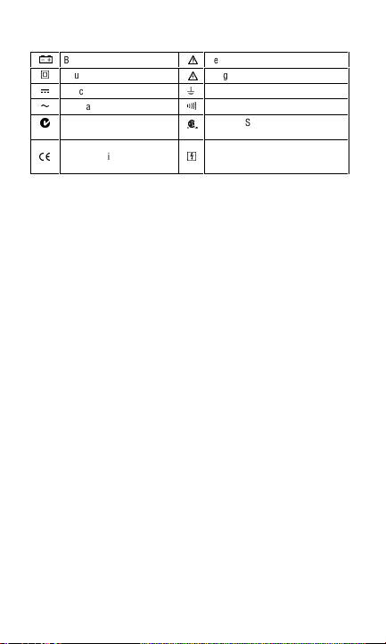
Symbols Used in this Manual
Battery
N
Double insulated
T
Direct Current
F
B
Alternating Current
;
Conforms to relevant
Australian standards.
Complies with EU directives
P
Refer to the manual
W
Dangerous Volt age
X
Earth Ground
J
R
Audible tone
Canadian Standards Association
)
(Canadian and US)
Application around and removal
,
from HAZARDOUS LIVE
conductors is permitted.
3
Page 5

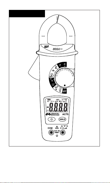
Introduction
The AC75 digital clamp-on multimeter, is a fully featured meter that also measures
temperature using a Type K probe (included). The AC75 has full Category safety
ratings and is CAT III, 600 V.
Making Measurements
Measurement F unctions
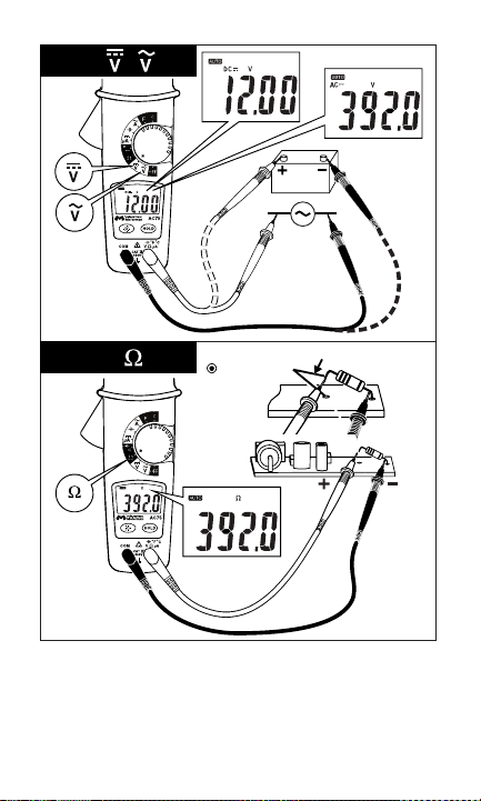
• AC and DC Volts (
• Resistance (
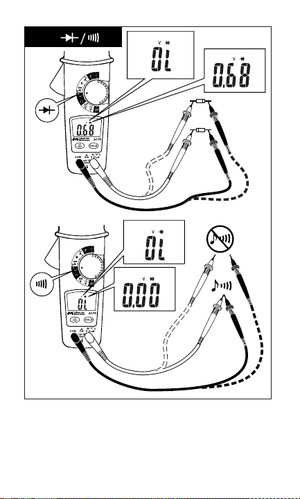
• Diode/Continuit y (
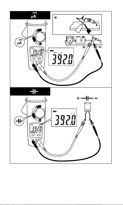
• DC Current (DC µA) See Figure
• Capacitance (
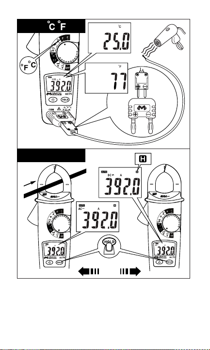
• Temperature (°C/°F) See Figure
• AC Current (
Additional Features
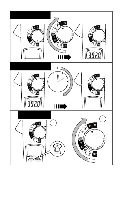
Auto Power Off/Auto Power Off Disable See Figures -2- and –3-
The meter will automatically shut itself off after approximately 10 minutes after
power is turned on, or no activity has occurred with the meter. The meter will beep
when it turns off. Turn the rotary dial to reactivate the meter.
The Auto Power Off feature can be disabled to keep the meter from going to sleep.
Press the BACKLIGHT button and then switch the rotary knob to power on the meter.
Backlight See Figure
The AC75 backlight illuminates the entire display for easy measurement viewing in
dark work environments. The backlight is activated for 60 seconds once the button is
pressed.
HOLD Measurem ents See Figure
The HOLD button allows the meter to capture and continuously display a
measurement reading. To use the HOLD feature, make a measurement, when the
reading has stabilized, press the HOLD button. The measurement value will be
captured on the display. Press the HOLD button again to release the value.
V/v
) See Figure -4-
O
) See Figure -5-
G/C
) See Figure –6-
P
) See Figure –8-
a
) See Figure –11-
–7-
–9-
-12-
-10-
Product Maintenance
Maintenance
Do not attempt to repair this meter. It contains no user serviceable parts. Repair or
servicing should only be performed by qualified personnel.
Cleaning
To clean the meter, periodically wipe the case with a soft moistened cloth. To avoid
damage to the plastic components do not use benzene, alcohol, acetone, ether, paint
thinner, lacquer thinner, ketone or other solvents to clean the meter.
4
Page 6

Troubleshooting
If the meter appears to operate improperly, check the following items first.
1. Review the operating instructions to ensure the meter is being used properly.
2. Make sure the battery is in good condition. The low battery symbol
when the battery falls below the level where accuracy is guaranteed. Replace a
low battery immediately.
Battery Replacement
To replace the battery
1. Turn the meter off and remove the test leads.
2. Loosen the screw and remove the battery door.
3. Replace the battery using an alkaline 9 V battery. See General Specifications for
detailed battery specifications.
4. Replace the battery cover and tighten the screw. Recycle the battery using
approved meth ods.
To avoid elect rical, shock remove the tes t leads from both the
meter and the tes t circuit before accessi ng the battery or the fus es.
Limited Warranty and Limitation of Liability
Your Meterman product will be free from defects in material and workmanship for
1 year from the date of purchase. This warranty does not cover fuses, disposable
batteries or damage from accident, neglect, misuse, alteration, contamination, or
abnormal conditions of operation or handling. Resellers are not authorized to extend
any other warranty on Fluke’s behalf. To obtain service during the warranty period,
return the product with proof of purchase to an authorized Meterman Test Tools
Service Center or to a Meterman dealer or distributor. See Repair Section for details.
THIS WARRANTY IS YOUR ONLY REMEDY. ALL O THER WARRANTIES - WHETHER
EXPRESS, IMPLIED OR STAUTORY - INCLUDING IMPLIED WARRANTIES OF
FITNESS FOR A P ARTICULAR PURPOSE OR ME RCHANTABILITY, ARE HER EBY
DISCLAIMED. MANUFACTURER SHALL NOT BE LIABLE FOR ANY SPECIAL,
INDIRECT, INCI DENTAL OR CONSEQUENTIAL DA MAGES OR LOSSES, ARISING
FROM ANY CAUSE OR THEORY. Since some states or countries do not allow the
exclusion or limitation of an implied warranty or of incidental or consequential
damages, this limitation of liability may not apply to you.
XW
WARNING
N
appears
5
Page 7

Repair
All test tools returned for warranty or non-warranty repair or for calibration should be
accompanied by the following: your name, company’s name, address, telephone
number, and proof of purchase. Additionally, please include a brief description of the
problem or the service requested and include the test leads with the meter. Nonwarranty repair or replacement charges should be remitted in the form of a check, a
money order, credit card with expiration date, or a purchase order made payable to
Meterman Test Tools.
In-Warranty Repairs and Replacement – All Countries
Please read the warranty statement that follows, and check your battery before
requesting repair. During the warranty period any defective test tool can be returned
to your Meterman Test Tools distributor for an exchange for the same or like
product. Please check the “Where to Buy” section on www.metermantesttools.com
for a list of distributors near you. Additionally, in the United States and Canada InWarranty repair and replacement units can also be sent to a Meterman Test Tools
Service Center (see below for address).
Non-Warranty Repairs and Replacement – US and Canada
Non-warranty repairs in the United States and Canada should be sent to a Meterman
Test Tools Service Center. Call Meterman Test Tools or inquire at your point of
purchase for current repair and replacement rates.
In USA In Canada
Meterman Test Tools Meterman Test Tools
1420 75th Street SW 400 Britannia Rd. E. Unit #1
Everett, WA 98203 Mississauga, ON L4Z 1X9
Tel: 888-993-5 853 Tel: 905-890-7600
Fax: 425-446-6390 Fax: 905-890-6866
Non-Warranty Repairs and Replacement – Europe
European non-warranty units can be replaced by your Meterman Test Tools
distributor for a nominal charge. Please check the “Where to Buy” section on
www.metermantesttools.com for a list of distributors near you.
European Correspondence Address*
Meterman Test Tools Europe
P.O. Box 1186
5602 BD Eindhoven
The Netherlands
*(Correspondence only – no repair or replacement available from this address.
European customers please contact your distributor.)
6
Page 8

Specifications
General Specifications
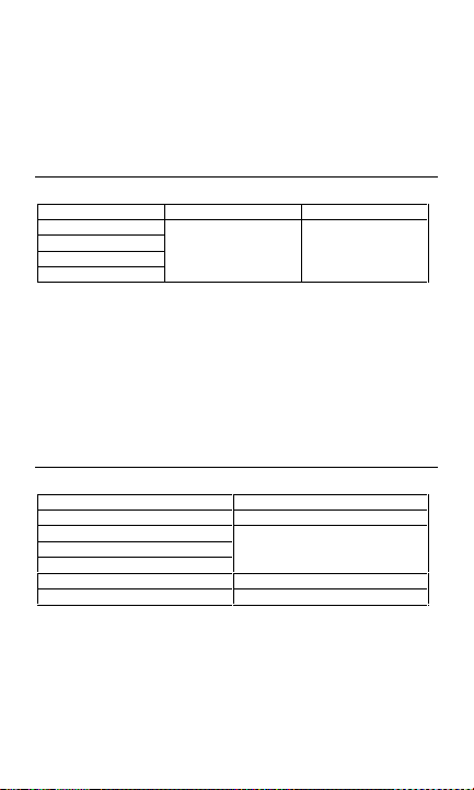
Display
3 ¾ digit large scale liquid crystal display (LCD)
Display Count
4000 counts
Measuring Rate
1.5 times per second
Overrange Display
0o
is displayed for Ω functions. Actual value is shown for A, V, and temperature
functions.
Automatic Power Off Time
Approximately 10 minutes after power on
Low battery indication
N
symbol is displayed when the battery voltage drops below the operating
The
level for accurate results.
Power
Single standard 9 V battery, NEDA160A.
Battery Life
200 hours with an alkaline 9 V battery.
Environmental Specifications
Indoor Use
Calibration
One year calibration cycle
Operating Temper ature
0 °C to 30 °C at ≤80 % R.H.
30 °C to 40 °C at ≤75 % R.H.
40 °C to 50 °C at ≤45 % R.H.
Storage Temper ature
-20 °C to 60 °C at 0 to 80 % R.H. (battery removed)
Overvoltage Category
IEC 61010-1 CAT III - 600 V, CAT II 1000 V, Pollution Degree 2
EN61010-2-032
CAN/CSA C22.2 No. 1010.1-92
CAN/CSA C22.2 No. 1010.1B-92
CAN/CSA C22.2 No. 1010.2.032-96
Altitude
<
2000 M (6562 Feet)
−
Conductor Size
<
32 mm diameter (1.25 in)
−
EMC
EN61326-1.
7
Page 9
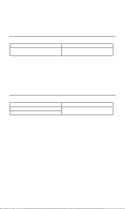
Shock Vibration
Sinusoidal vibration per MIL-PRF-28800F (5 to 55 Hz, 3 g maximum)
Drop Protection
4 foot drop to hardwood on concrete floor
Electrical Specifications
Accuracy
±(% reading + number of digits) at 23 °C ±5 °C at <80 % R.H.
Temperature Coefficient
Add 0.2 x (Specified Accuracy)/°C, <.18 °C, >28 °C.
DC/AC VOLTS
Range DC Accuracy AC Accuracy
4.000 V
40.00 V
400.0 V
1000 V dc/750 v a c
Overvoltage Protection
DC 1000 V or AC 750 V rms
Input Impedance
10 MΩ//less than 100 ρF
CMRR/NMRR (Common Mode Rejection Ratio/Normal Mode Rejection Ratio)
V ac
CMRR > 60 dB at DC, 50 Hz/60 Hz
V dc
CMRR > 100 dB at DC, 50 Hz/60 Hz
NMRR > 50 dB at DC, 50 Hz/60 Hz
AC Conversion Type
Average sensing rm s indication.
±(0.9% + 2 dgt) ±(1.5% + 5 dgt)
50 Hz to 500 Hz
Resistance
Range Accuracy
2
400.0 Ω±(1.0% + 2 dgt)
4.000 KΩ
40.00 KΩ
400.0 KΩ
4.000 MΩ±(1.0% + 2 dgt)
1
40.00 MΩ±(1.5% + 2 dgt)
±(0.7% + 2 dgt)
8
Page 10
Overload Protection
1000 V dc/750 V ac
Open Circuit Voltage
-1.3 V approx.
1
<100 dgt rolling
2
10 dgt rolling
Diode Check and Continuity
Resolution Accuracy
10 mV ±(1.5% + 5 dgt)
Max Test Current
1.5 mA
Max Open Current
3 V
Overload Protection
1000 V dc/750 V ac
Continuity
Built-in buzzer sounds when resistance is less than approximately 100 Ω. Response time is
approximately 100 msec
From 0.4 V to 0. 8 V
DC µA
Range Accuracy
400.0 µA
4000 µA
Voltage Burden
< 5 mV/µA
Overload Protection
1000 V dc/750 V ac
±(1.0% + 2 dgt)
9
Page 11
Capacitance
Range Accuracy
4.000 nF ±(3.0% + 20 dgt)
40.00 nF
400.0 nF
4.000 µF
40.00 µF
400.0 µF
1
4.000 mF
Overload Protection
1000 V dc/750 V ac
1
< 50 dgt fluctuat ing
±(2.0% + 8 dgt)
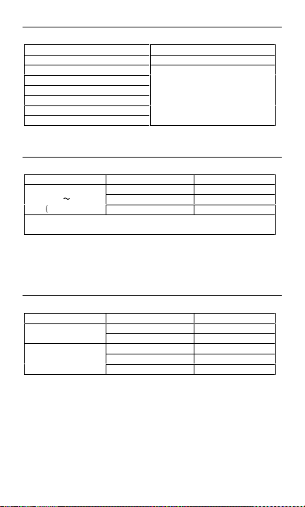
AC Current
Function Range AC Accuracy
A
B
(50 to 60 Hz)
*0.0 to 500.0 A Continuous
501 A to 600.0 A 10 minutes maximum followed by 10 minutes cooling period.
Overload Protection
1000 V dc/750 V ac
AC Conversion Type
Average sensing rm s display
Position Error
±1.5% of reading
0.0 to 100.0 A ±(1.9% + 2 A)
100.0 to 400.0 A
401 to 600.0 A*
±(1.9% + 1 A)
±(2.5% + 7 A)
Temperature
Function Range Accuracy
°C
°F
Overload Protection
1000 V dc/750 V ac
-40 °C to 0.1 °C 1% ± 4 °C
0 °C to 400.0 °C 1% ± 3 °C
-40 °F to 32 °F 1% ± 8 °F
32 °F to 750 °F 1% ± 6 °F
750 °F to 1000 °F 2% ± 8 °F
10
Page 12
Clamp Meter
1
11
Page 13
Off/On
2
Auto Power Off
3
10 min
Auto Off Disable
1
2
12
Page 14
4
5
Disconnect
13
Page 15
14615
Page 16
7
Disconnect
8
Discharge
Page 17
9
10
392
K
Data Hold
Press
16
Page 18

11
392
I
OK
I
I
12
Back Light
Press
17
OK
I
OK
I + (-I) = 0
Page 19

18
Page 20

Multimètre à pince AC75
Table des matières
Consignes de sécurité...........................................................................................2
Symboles utilisés dans ce mode d’emploi .........................................................3
Introduction ...........................................................................................................4
Mesures..............................................................................................................4
Autres fonctions .................................................................................................4
Entretien du produit ..............................................................................................4
Maintenance .......................................................................................................4
Nettoyage ...........................................................................................................5
Dépannage..........................................................................................................5
Remplacement de la pile....................................................................................5
Limites de garantie et de responsabilité ...............................................................5
Réparation .............................................................................................................6
Caractéristiques.....................................................................................................7
Caractéristiques générales .................................................................................7
Caractéristiques ambiantes................................................................................7
Caractéristiques électriques ...............................................................................8
Français
1
Page 21

Pour assurer un fonctionnement et une utilisation sans danger du multimètre, suivez
ces instructions. Le non-respect des mises en garde peut entraîner des blessures
graves, voire la mort.
• Pour éviter les chocs électriques ou les risques de blessures, respecter les
consignes suivantes :
• Ne pas utiliser le multimètre s’il est endommagé. Inspecter le boîtier du
multimètre avant d’utiliser l'appareil. Rechercher les éventuelles fissures ou les
parties de plastique manquantes. Inspecter particulièrement l’isolant autour des
connecteurs.
• Inspecter les cordons de test. Ne pas les utiliser si l’isolant est endommagé ou si
des parties métalliques sont mises à nu. Vérifier la continuité des cordons de
mesure.
• Remplacer les cordons de mesure endommagés avant d’utiliser le multimètre.
• Cet appareil doit être utilisé de la manière spécifiée par le fabricant afin de ne pas
entraver la protection intégrée.
• Ne pas utiliser le multimètre s’il ne fonctionne pas normalement. Sa protection
est peut-être défectueuse. En cas de doute, faire vérifier l’appareil.
• Ne pas utiliser le multimètre à proximité de gaz explosifs, de vapeurs ou de
poussière.
• Ne jamais appliquer de tension supérieure à la tension nominale, indiquée sur le
multimètre, entre les bornes ou entre une borne et la prise de terre.
• Vérifier le fonctionnement du multimètre en mesurant une tension connue avant
son utilisation.
• Mettre le circuit hors tension avant de brancher le multimètre au circuit pour
mesurer un courant. Veiller à placer le multimètre en série avec le circuit.
• Ne pas essayer de réparer ce multimètre. Il ne contient pas de pièces pouvant
être remplacées par l’utilisateur.
• Procéder avec prudence en travaillant avec des tensions supérieures à 30 V c.a.
efficace, 42 V maximum ou 60 V c.c. Ces tensions présentent un risque
d’électrocution.
• En utilisant les sondes, placer les doigts au-delà de leur collerette de protection.
• Connecter le commun de la sonde de test avant la polarité au potentiel. Pour
débrancher les sondes de test, commencer par celle au potentiel.
• Retirer les cordons de test du multimètre avant d’ouvrir le capot de pile.
• Ne pas utiliser le multimètre avec le capot de pile démonté ou desserré.
• Pour éviter les mesures erronées, ce qui pose des risques d’électrocution et de
blessure, remplacer les piles dès l'apparition du témoin de pile faible (
• Utiliser uniquement une pile de 9 volts correctement installée dans le boîtier du
multimètre pour alimenter le multimètre.
• Pour éviter les risques d’incendie ou de chocs électriques, ne pas brancher le
thermocouple aux circuits sous tension.
• Débrancher l’alimentation du circuit et décharger tous les condensateurs à
tension élevée avant de contrôler la résistance, la continuité, les diodes ou la
capacité.
Consignes de sécurité
N
).
2
Page 22

Symboles utilisés dans ce mode d’emploi
Pile
N
Double isolation
T
Courant continu
F
B
Courant alternatif
;
Conformes aux normes
australiennes pertinentes.
Conforme aux directives de
P
l’UE
Se reporter au mode d’emploi
W
Tension dangereuse
X
Prise de terre
J
R
Signal sonore
Association canadienne de
)
normalisation
(Canada et Etats-Unis)
Son application et son retrait à
,
proximité de conducteurs sous
TENSION DANGE REUSE sont
autorisés.
3
Page 23

Introduction
Le multimètre numérique à pince AC75 est un appareil à fonctionnalités complètes
qui mesure également la température en utilisant une sonde de type K (incluse). Le
AC75 possède des caractéristiques complètes de sécurité de catégorie de type CAT
III, 600 V.
Mesures
Fonctions de mes ure
• Volts c.a. et c.c. (
• Résistance (
• Diode/Continuit é (
• Courant c.c. (µA c.c.) Voir Figure
• Capacité (
• Température (°C/°F) Voir Figure
• Courant c.a. (
Autres fonctions
Arrêt automatique/Désactiver la fonction d’arrêt automatique
Le multimètre s’éteint automatiquement environ 10 minutes après sa mise sous
tension, ou si aucune activité ne s’est produite sur le multimètre. Le multimètre émet
un bip sonore lorsqu’il s’éteint. Réglez le cadran rotatif pour réactiver l’appareil.
Vous pouvez empêcher la mise en veille du multimètre en désactivant la fonction
d’arrêt automatique. Appuyez sur le bouton BACKLIGHT, puis réglez le commutateur
rotatif pour allumer le multimètre.
Rétroéclairage Voir Figure
Le rétroéclairage du multimètre AC75 éclaire l’affichage pour permettre de visualiser
facilement les mesures dans les environnements faiblement éclairés. Le
rétroéclairage est activé pendant 60 secondes après la pression du bouton.
Mesures en maintien HOLD Voir Figure
Le bouton HOLD permet au multimètre de capturer et d’afficher en continu la valeur
mesurée. Pour utiliser la fonction de maintien HOLD, prenez une mesure, puis une
fois le relevé stabilisé, appuyez sur le bouton HOLD. La valeur mesurée est ensuite
maintenue sur l’affichage. Une nouvelle pression du bouton HOLD libère la valeur
affichée.
V/v
) Voir Figure -4-
O
) Voir Figure -5-
G/C
) Voir Figure -6-
P
) Voir Figure -8-
a
) Voir Figure -11-
Voir Figures
-7-
-9-
-2- et -3-
-12-
-10-
Entretien du produit
Maintenance
Ne tentez pas de réparer ce multimètre. Il ne contient pas de pièces réparables par
l’utilisateur. Les réparations ou les interventions ne doivent être effectuées que par
un personnel qualifié.
4
Page 24

Nettoyage
Pour nettoyer le multimètre, essuyez périodiquement le boîtier à l'aide d’un chiffon
doux imbibé d’eau. N’utilisez pas de benzène, d’alcool, d’éther, de diluant pour
peinture, de diluant à peinture-laque, de cétone ou d’autres solvants lors du
nettoyage du multimètre afin de ne pas endommager ses composants en plastique.
Dépannage
Si le multimètre ne semble pas fonctionner normalement, vérifiez d’abord les
éléments suivants.
1. Relisez les consignes d’utilisation pour confirmer que le multimètre est utilisé
correctement.
2. Assurez-vous que la pile est en bon état. Le symbole de pile faible N apparaît
lorsque la tension de la pile tombe en dessous du niveau garantissant la
précision. Remplacez immédiatement une pile faible.
Remplacement de la pile
Pour remplacer la pile
1. Eteignez le multimètre et retirez les cordons de mesure.
2. Desserrez la vis et retirez le capot de pile.
3. Remplacez la pile en utilisant une pile 9 V alcaline. Reportez-vous aux
Caractéristiques générales pour plus de détails sur les spécifications de la pile.
4. Replacez le capot du logement de la pile et resserrez la vis. Recyclez la pile en
utilisant les méthodes appro uvées.
Pour éviter les chocs électriques, retirer les cordons de mesure du
multimètre et du circuit de test avant d’accéder à la pile ou aux
fusibles.
Limites de garantie et de responsabilité
Meterman garantit l’absence de vices de matériaux et de fabrication de ce produit dans des
conditions normales d’utilisation et d’entretien pen dant une période d’un an prenan t effet à la
date d’achat. Cette garantie ne s’applique pas aux fusibles, aux piles jetables ni à tout produit
mal utilisé, modifié, contaminé, négligé ou endommagé par accident ou soumis à des
conditions anormales d’utilisation et de manipulation. Les d istributeurs agréés par Fluke ne
sont pas autorisés à appliquer une garantie plus étendue au nom de Fluke. Pour bénéficier de
la garantie, renvoyez le produit accompagné d’un justificatif d ’achat auprès d’un centre de
services agréé par Meterman Test ou du distributeur ou du revendeur Meterman. Voir la
section Réparation pour tous les détails. LA PRESENTE GARANTIE EST LE SEUL ET
EXCLUSIF RECOURS TOUTES A UTRES GARANTIES, EXPLICITES, IMPLICITES OU
STATUTAIRES, NOTAMMENT LE CAS ECHEANT LES GARANTIES DE QUALITE MARCHANDE
OU D’ADAPTATION A UN OBJECTIF PARTICULIER SONT EXCLUES PAR LES PRESENTES.
LE FABRICANT NE SERA EN AUCUN CAS TENU RESPONSABLE DE DOMMAGES
PARTICULIERS, INDIRECTS, ACCIDENTELS OU CONSECUTIFS, NI D’AUCUNS DEGATS OU
PERTES DE DONNEES, SUR UNE BASE CONTRACTUELLE, EXTRA-CONTRACTUELLE OU
AUTRE. Etant donné que certains pays ou états n’admettent pas les limitations d’une
condition de garantie implicite, ou l’exclusion ou la limitation de dégâts accidentels ou
consécutifs, les limi tations et les exclusions de cette garantie ne s’appliquent pas
obligatoirement à ch aque acheteur.
XW
AVERTISSEMENT
5
Page 25

Réparation
Tous les outils de test renvoyés pour un étalonnage ou une réparation couverte ou
non par la garantie doivent être accompagnés des éléments suivants : nom, raison
sociale, adresse, numéro de téléphone et justificatif d'achat. Ajoutez également une
brève description du problème ou du service demandé et incluez les cordons de test
avec le multimètre. Les frais de remplacement ou de réparation hors garantie doivent
être acquittés par chèque, mandat, carte de crédit avec date d'expiration ou par bon
de commande payable à l'ordre de Meterman Test Tools.
Remplacements et réparations sous garantie – Tous pays
Veuillez lire la déclaration de garantie qui suit, et vérifier la pile avant de demander
une réparation. Pendant la période de garantie, tout outil de test défectueux peut être
renvoyé auprès de votre distributeur Meterman Test Tools pour être échangé contre
un produit identique ou similaire. Consultez la section « Where to Buy » sur le site
www.metermantesttools.com pour obtenir la liste des distributeurs dans votre
région. Au Canada et aux Etats-Unis, les appareils devant être remplacé ou réparé
sous garantie peuvent également être envoyés dans un centre de services Meterman
Test Tools (voir les adresses ci-dessous).
Remplacements et réparations hors garantie – Canada et Etats-Unis
Les appareils à réparer hors garantie au Canada et aux Etats-Unis doivent être
envoyés dans un centre de services Meterman Test Tools. Appelez Meterman Test
Tools ou renseignez-vous auprès de votre lieu d’achat pour connaître les tarifs en
vigueur pour le remplacement ou les réparations.
Aux Etats-Unis Au Canada
Meterman Test Tools Meterman Test Tools
th
Street SW 400 Britannia Rd. E. Unit #1
1420 75
Everett, WA 98203 Mississauga, Ontario L4Z 1X9
Tél. : 888-993- 5853 Tél. : 905-890-7600
Fax : 425-446-6390 Fax : 905-890-6866
Remplacements et réparations hors garantie – Europe
Les appareils européens non couverts par la garantie peuvent être remplacés par
votre distributeur Meterman Test Tools pour une somme nominale. Consultez la
section « Where to Buy » sur le site www.metermantesttools.com pour obtenir la
liste des distributeurs dans votre région.
Adresse postale européenne*
Meterman Test Tools Europe
P.O. Box 1186
5602 B.D. Eind hoven
Pays-Bas
*(Réservée à la correspondance – Aucun remplacement ou réparation n’est possible
à cette adresse. Nos clients européens doivent contacter leur distributeur.)
6
Page 26

Caractéristiques
Caractéristiques générales
Affichage
Grand afficheur à cris taux liquides (LCD) à 3 ¾ chif fres de résolution
Compte d’affichage
4000 comptes
Vitesse de mesure
1,5 fois par seconde
Affichage de dépassement de gamme
0o
est affiché pour les fonctions Ω. La valeur réelle apparaît pour les fonctions de
température et A, V.
Mise en veille automatique
Environ 10 minutes après le démarrage
Indication de pile faible
N
Le symbole
opérationnel permettant des résultats précis.
Alimentation
Pile standard de 9 V, NEDA160A.
Durée de vie de la pile
200 heures avec une pile alcaline de 9 V.
Caractéristiques ambiantes
Utilisation à l’intérieur des locaux
Etalonnage
Cycle d’étalonnage d’un an
Température en fonctionnement
de 0 °C à 30 °C à ≤80 % H.R.
de 30 °C à 40 °C à ≤75 % H.R.
de 40 °C à 50 °C à ≤45 % H.R.
Température d’ent reposage
entre -20 °C et 60 °C à 0 à 80 % H.R. (sans la pile)
Catégorie de surtension
CEI 61010-1 CAT III - 600 V, CAT II 1000 V, degré de pollution 2
EN61010-2-032
CAN/CSA C22.2 No. 1010.1-92
CAN/CSA C22.2 No. 1010.1B-92
CAN/CSA C22.2 No. 1010.2.032-96
Altitude
<
−
Calibre de cond ucteur
<
−
CEM
EN61326-1.
apparaît lorsque la tension de la pile tombe en dessous du niveau
2000 m (6562 pie ds)
32 mm de diamètre (1,25 po)
7
Page 27

Résistance aux chocs/vibrations
Vibration sinusoïdale selon MIL-PRF-28800F (5 à 55 Hz, 3 g maximum)
Protection contre les chutes
Chute à 1,20 mètre sur sol en béton sur parquet
Caractéristiques électriques
Précision
±(% lecture + nombre de chiffres) à 23 °C ±5 °C avec <80 % H.R.
Coefficient the rmique
Ajouter 0,2 x (précision spécifiée)/°C, <0,18 °C, >28 °C.
Volts c.c./c.a.
Gamme Précision c.c. Précision c.a.
4,000 V
40,00 V
400,0 V
1000 V c.c./750 V
c.a.
Protection contre les surtensions
1000 V c.c. ou 750 V c.a. eff.
Impédance d’entrée
Ω//inférieur à 100 ρF
10 M
CMRR/NMRR (Taux d’élimination en mode commun/Taux d’élimination en mode normal)
V c.a.
> 60 dB à c.c., 50 Hz/60 Hz
CMRR
V c.c.
> 100 dB à c.c., 50 Hz/60 Hz
CMRR
> 50 dB à c.c., 50 Hz/60 Hz
NMRR
Type de conversion c.a.
Mesure eff. à détec tion moyenne
±(0,9 % + 2 chiffres) ±(1,5 % +
5 chiffres)
50 Hz à 500 Hz
Résistance
Gamme Précision
2
400,0 Ω±(1,0 % + 2 chiffres)
4,000 KΩ
40,00 KΩ
400,0 KΩ
4,000 MΩ±(1,0 % + 2 chiffres)
1
40,00 MΩ±(1,5 % + 2 chiffres)
±(0,7 % + 2 chiffres)
8
Page 28

Protection contre les surcharges
1000 V c.c./750 V c.a.
Tension en circuit ouvert
-1,3 V approx.
1
<défilement à 100 chiffres
2
défilement à 10 chi ffres
Contrôle de diodes et continuité
Résolution Précision
10 mV
Courant de test max
1,5 mA
Courant d’ouverture max
3 V
Protection contre les surcharges
1000 V c.c./750 V c.a.
Continuité
L’avertisseur intégré r etentit lorsque la résistance es t inférieure à environ 100
de réponse est d’environ 100 ms
±(1,5 % + 5 chiffres)
de 0,4 V à 0,8 V
µA c.c.
Gamme Précision
400,0 µA
4000 µA
Tension de charge
< 5 mV/µA
Protection contre les surcharges
1000 V c.c./750 V c.a.
±(1,0 % + 2 chiffres)
Ω. Le temps
9
Page 29

Capacité
Gamme Précision
4,000 nF ±(3,0 % + 20 chiffres)
40,00 nF
400,0 nF
4,000 µF
40,00 µF
400,0 µF
1
4,000 mF
Protection contre les surcharges
1000 V c.c./750 V c.a.
1
< fluctuation à 50 chiffres
±(2,0 % + 8 chiffres)
Courant c.a.
Fonction Gamme Précision c.a.
A
B
(50 à 60 Hz)
*0,0 à 500,0 A C ontinu
501 à 600,0 A 10 minutes maximum suivis d’une 10 minute période de
refroidissement.
Protection contre les surcharges
1000 V c.c./750 V c.a.
Type de conversion c.a.
Mesure eff. à détection moyenne
Erreur de po sition
±1,5 % de lecture
0,0 à 100,0 A
100,0 à 400,0 A ±(1,9 % + 1 A)
401 à 600,0 A* ±( 2,5 % + 7 A)
±(1,9 % + 2 A)
Température
Fonction Gamme Précision
°C
°F
Protection contre les surcharges
1000 V c.c./750 V c.a.
-40 °C à 0,1 °C1 % ± 4 °C
0 °C à 400,0 °C1 % ± 3 °C
-40 °F à 32 °F1 % ± 8 °F
32 °F à 750 °F1 % ± 6 °F
750 °F à 1000 °F2 % ± 8 °F
10
Page 30

AC75 Clamp-on Multimeter
Inhalt
Sicherheitsinformationen ......................................................................................2
Symbole in diesem Handbuch ...........................................................................3
Einleitung...............................................................................................................4
Messungen durchführen ....................................................................................4
Zusätzliche Funktionen.......................................................................................4
Produktwartung.....................................................................................................4
Wartung..............................................................................................................4
Reinigung ...........................................................................................................4
Fehlerbehebung..................................................................................................5
Ersetzen der Batterie ..........................................................................................5
Beschränkte Gewährleistung und Haftungsbeschränkung ...................................5
Reparatur...............................................................................................................6
Technische Daten ..................................................................................................7
Allgemeine Spezifikationen ................................................................................7
Umgebungsspezifikationen ................................................................................7
Elektrische Spezifikationen.................................................................................8
Deutsch
1
Page 31

Zur Gewährleistung von sicherem Betrieb und Gebrauch des Messgeräts diese Anleitungen
befolgen. Nichtbeachtung der Warnungen kann zu schweren Verletzungen oder Tod führen.
• Zur Vermeidung von Stromschlag oder Verletzungen folgende Richtlinien einhalten:
• Das Messgerä t nicht verwenden, wenn es besch ädigt ist. Vor dem Gebrauch des
Messgeräts das Gehäuse untersuchen. Nach Rissen oder h erausgebrochenem
Kunststoff suchen. Die Isolierung im Bereich der Anschlüsse besonders sorgfältig
untersuchen.
• Die Messleitungen bezüglich beschädigter Isolierung und exponiertem Metall
untersuchen. Kontinuität der Messleitungen prüfen.
• Vor Gebr auch des Messgeräts beschädigte Messl eitungen ersetzen.
• Wenn dieses Produkt in einer hier nicht beschriebenen Art verwendet wird, wird der
durch das Gerät gebotene Schutz unter Umständen beeinträchtigt.
• Das Messger ät nicht verwenden, wenn es Fu nktionsstörungen aufweist. Unter
Umständen sind die Sicherheitsvorkehrungen beeinträchtigt. Im Zweifelsfall das
Messgerät von einer Ser vicestelle prüfen lassen.
• Das Messgerä t nicht in Umgebungen mit explosiven Gasen, Dampf oder Staub
verwenden.
• Zwischen d en Anschlüssen bzw. zwischen den A nschlüssen und Erde nie eine Spannung
anlegen, die die am M essgerät angegebene Nennspannung überschreitet.
• Vor dem Gebrauch die Funktionsfähigkeit des Messgeräts durch Messen einer
bekannten Spannung prüfen.
• Beim Messen von Strom vor dem Anschließen d es Messgeräts an den Stromkreis den
Strom des Stromkreis es abschalten. Darauf achten, dass d as Messgerät mit dem
Stromkreis in Reihe gesch altet ist.
• Nicht versuchen dieses Messgerät zu reparieren. Es gibt keine kundenseitig wartbaren
Teile.
• Bei Arbeiten mit mehr als 30 V Wechselspannung eff., 42 V Spitze oder 60 V
Gleichspannung Vorsicht walten lassen. Solche Spannungen bergen Stromschlaggefahr.
• Bei der Verwendung der Messspitzen die Finger hinter dem Fingerschutz der
Messspitzen halten.
• Vor dem Anschließen der stromführenden M essleitung die Masse-Messleitung
anschließen. Beim Ab nehmen der Messleitungen die stromführende Messleitung zuerst
trennen.
• Vor dem Öffnen der Batteriefachabdeckung die Messleitungen vom Messgerät trennen.
• Das Messger ät nicht betreiben, wenn die B atteriefachabdeckung entfernt oder lose ist.
• Zur Vermeidung falscher Messwerte, die zu Stromschlag oder Verletzungen führen
können, die Batterien ersetzen, sobald die Anzeige für schwache Batterien (
eingeblendet wird.
• Zur Stromversorgung des Messgeräts ausschließlich eine or dnungsgemäß im
Messgerätgehäuse inst allierte 9-Volt-Batterie verwen den.
• Zur Vermeidung von Feuer- und Stromschlaggefahr das Thermoelement nicht an
spannungsführende Stromkreise anschließen.
• Vor dem Prüfen von Widerstand, Kontinuität, Dioden oder Kapazität den Strom des
Stromkreises abschalten und alle Hochspannungskondensatoren entladen.
Sicherheitsinformationen
N
)
2
Page 32

Symbole in diesem Handbuch
N
Batterie
Schutzisoliert
T
Gleichstrom
F
B
Wechselstrom
;
Übereinstimmung mit den
relevanten Australischen
Standards
Übereinstimmung mit EU-
P
Vorschriften
Im Handbuch nachlesen.
W
Gefährliche Spannung
X
Erde, Masse
J
R
Akustischer Alarm
Canadian Standards Association
)
(Kanadische und US-Normen)
Anwendung in der Umgebung von
,
gefährlichen STROMFÜHRENDEN
LEITERN zulässig.
3
Page 33

Einleitung
Das digitale AC75 Clamp-on Multimeter ist ein vielfältiges Messgerät, das unter
Verwendung einer Typ- K-Messsonde (enthalten) auch Temperatur misst. Das AC75
verfügt über uneingeschränkte Kategoriesicherheitsnennbelastbarkeit und ist CAT III,
600 V.
Messungen durchführen
Messfunktione n
• Wechsel- und Gleichspannung Volt (
• Widerstand (
• Diode/Kontinuität (
• Gleichstromstärke (DC µA) Siehe Abbildung
• Kapazität (
• Temperatur (°C/°F) Siehe Abbildung
• Wechselstromstärke (
Zusätzliche Funktionen
Automatische Abschaltung/Automatische Abschaltung deaktivieren
Das Messgerät schaltet sich automatisch ab ungefähr 10 Minuten nach dem
Einschalten, bzw. wenn 10 Minuten lang keine Aktivität auftritt. Das Messgerät
piepst, wenn es sich abschaltet. Den Drehknopf drehen, um das Messgerät zu
reaktivieren.
Diese Funktion kann deaktiviert werden, um zu verhindern, dass das Messgerät in
den Schlafmodus gesetzt wird. Die Taste BACKLIGHT drücken und dann den
Drehknopf bedienen, um das Messgerät einzuschalten.
Hintergrundbeleuchtung Siehe Abbildung
Die Hintergrundbeleuchtung des AC75 beleuchtet die gesamte Anzeige für müheloses
Ablesen der Messwerte in dunklen Arbeitsumgebungen. Die Hintergrundbeleuchtung
bleibt nach dem Drücken der Taste 60 Sekunden lang aktiviert.
HOLD-Messunge n Siehe Abbildung
Durch Drücken der HOLD-Taste erfasst das Messgerät eine Messung und zeigt sie
kontinuierlich an. Zum Verwenden der HOLD-Funktion eine Messung durchführen
und die HOLD-Taste dr ücken, wenn sich die Messung stabilisiert hat. Der gemessene
Wert wird auf der Anzeige festgehalten. Wenn die HOLD-Taste erneut gedrückt wird,
wird der Wert freigegeben.
O
) Siehe Abbildung -5-
G/C
P
) Siehe Abbildung –8-
a
V/v
) Siehe Abbildung -4-
) Siehe Abbildung –6-
) Siehe Abbildung –11-
Siehe Abbildungen
-2- und –3-
-12-
-10-
–7-
–9-
Produktwartung
Wartung
Nicht versuchen dieses Messgerät zu repariere n. Es enthält keine kundenseitig wartbaren Teile.
Reparatur- oder Servicearbeiten dürfen nur durch ausgewiesenes Fachpersonal durchgeführt
werden.
Reinigung
Zur Reinigung des Messgeräts dieses von Zeit zu Zeit mit einem weichen,
angefeuchteten Lappen abwischen. Um eine Beschädigung der Plastikteile zu
vermeiden, kein Benzin, Alkohol, Azeton, Äther, Farb- oder Lackverdünner, Keton
oder andere Lösungsmittel zur Reinigung des Messgeräts verwenden.
4
Page 34

Fehlerbehebung
Wenn das Messgerät nicht ordnungsgemäß zu funktionieren scheint, zuerst die
folgenden Punkt e prüfen.
1. Die Bedienungsanleitung prüfen, um sicherzustellen, dass das Messgerät
ordnungsgemäß verwendet wird.
2. Sicherstellen, dass die Batterie in einwandfreiem Zustand ist. Das
Batterieladesymbol
den Wert abfällt, der die Messgenauigkeit gewährleistet. Eine schwache Batterie
unverzüglich ersetzen.
Ersetzen der Batterie
Ersetzen der B atterien
1. Das Messgerät ausschalten und alle Messleitungen entfernen.
2. Die Schraube lösen und die Batteriefachabdeckung abnehmen.
3. Die Batterie durch eine alkalische 9-V-Batterie ersetzen. Für ausführliche
Batteriespezifikationen siehe „Allgemeine Spezifikationen“.
4. Die Batteriefachabdeckung wieder anbringen und die Schraube anziehen. Die
Batterie gemäß zulässigen Methoden recyceln.
Zur Vermeidung von Stromschlag vor dem Ersetzen der Batterie
oder von Sicher ungen die Messleitunge n vom Messgerät und vom
zu prüfenden Schaltkreis entfernen.
Beschränkte Gewährleistung und Haftungsbeschränkung
Es wird gewährleistet, dass dieses Meterman-Produkt für die Dauer von einem Jahr
ab dem Kaufdatum frei von Material- und Fertigungsdefekten ist. Diese
Gewährleistung erstreckt sich nicht auf Sicherungen, Einwegbatterien oder Schäden
durch Unfälle, Nachlässigkeit, Missbrauch, Änderungen oder abnormale
Betriebsbedingungen bzw. unsachgemäße Handhabung. Die Verkaufsstellen sind
nicht dazu berechtigt, diese Gewährleistung im Namen von Fluke zu erweitern. Um
während der Gewährleistungsperiode Serviceleistungen zu beanspruchen, das
Produkt mit Kaufnachweis an ein autorisiertes Meterman Test Tools Service-Center
oder an einen Meterman-Fachhändler/-Distributor einsenden. Einzelheiten siehe
Abschnitt „Reparatur“. DIESE GEWÄHRLEISTUNG STELLT DEN EINZIGEN UND
ALLEINIGEN RECH TSANSPRUCH AUF SCHADENERS ATZ DAR. ALLE ANDEREN
GEWÄHRLEISTUN GEN - VERTRAGLICH GEREG ELTE ODER GESETZLICHE
VORGESCHRIEBENE - EINSCHLIESSLICH DER GESETZLICHEN GEWÄHRLEISTUNG
DER MARKTFÄHIGK EIT UND DER EIGNUNG FÜR EINEN BESTIMMTEN ZWECK,
WERDEN ABGELE HNT DER HERSTELLER ÜBERNI MMT KEINE HAFTUNG FÜR
SPEZIELLE, INDI REKTE, NEBEN- ODER FOLGESC HÄDEN ODER VERLUSTE, DIE AUF
BELIEBIGER URSACHE ODER RECHTSTHEORIE BERUHEN. Weil einige Staaten oder
Länder den Ausschluss oder die Einschränkung einer implizierten Gewährleistung
sowie von Begleit- oder Folgeschäden nicht zulassen, ist diese
Gewährleistungsbeschränkung möglicherweise für Sie nicht gültig.
N
wird eingeblendet, wenn die Spannung der Batterie unter
XW
ACHTUNG
5
Page 35

Reparatur
Zu allen Geräten, die zur Reparatur oder Kalibrierung im Rahmen der Garantie oder
außerhalb der Garantie eingesendet werden, muss folgendes beigelegt werden: Name
des Kunden, Firmenname, Adresse, Telefonnummer und Kaufbeleg. Zusätzlich bitte
eine kurze Beschreibung des Problems oder der gewünschten Wartung sowie die
Messleitungen dem Messgerät beilegen. Die Gebühren für Reparaturen außerhalb der
Garantie oder für den Ersatz von Instrumenten müssen als Scheck, Geldanweisung,
Kreditkarte (Kreditkartennummer mit Ablaufdatum) beglichen werden oder es muss
ein Auftrag an Meterman Test Tools formuliert werden.
Garantiereparaturen oder -austausch - alle Länder
Bitte die nachfolgende Garantieerklärung lesen und die Batterie prüfen, bevor
Reparaturen angefordert werden. Während der Garantieperiode können alle defekten
Geräte zum Umtausch gegen dasselbe oder ein ähnliches Produkt an den Meterman
Test Tools-Distributor gesendet werden. Ein Verzeichnis der zuständigen
Distributoren ist im Abschnitt „Where to Buy“ (Verkaufsstellen) auf der Website
www.metermantesttools.com zu finden. Darüber hinaus können in den USA und in
Kanada Geräte an ein Meterman Test Tools Service-Center (Adresse siehe weiter
unten) zur Reparatur oder zum Umtausch eingesendet werden.
Reparaturen und Austausch außerhalb der Garantie - USA und Kanada
Für Reparaturen außerhalb der Garantie in den Vereinigten Staaten und in Kanada
werden die Geräte an ein Meterman Test Tools Service-Center gesendet. Auskunft
über die derzeit geltenden Reparatur- und Austauschgebühren erhalten Sie von
Meterman Test Tools oder der Verkaufsstelle.
In den USA: In Kanada:
Meterman Test Tools Meterman Test Tools
1420 75th Street SW 400 Britannia Rd. E. Unit #1
Everett, WA 98203 Mississauga, ON L4Z 1X9
Tel.: 888-993-5853 Tel.: 905-890-7600
Fax: 425-446-6390 Fax: 905-890-6866
Reparaturen und Austausch außerhalb der Garantie - Europa
Geräte außerhalb der Garantie können durch den zuständigen Meterman Test ToolsDistributor gegen eine Gebühr ersetzt werden. Ein Verzeichnis der zuständigen
Distributoren ist im Abschnitt „Where to Buy“ (Verkaufsstellen) auf der Website
www.metermantesttools.com zu finden.
Korrespondenzanschrift für Europa*
Meterman Test Tools Europe
P. O. Box 1186
5602 BD Eindhoven
Niederlande
*(Nur Korrespondenz – keine Reparaturen, kein Umtausch unter dieser Anschrift.
Kunden in Europa wenden sich an den zuständigen Distributor.)
6
Page 36

Technische Daten
Allgemeine Spezifikationen
Display
3 ¾ Stellen-LCD, Großanzeige
Zähleranzeige
4000 Zählwerte
Messrate
1,5 Mal pro Sekunde
Überschreitun gsanzeige
0o
wird angezeigt für Ω-Funktionen. Effektiver Wert wird angezeigt für A-, V- und
Temperaturfunktionen.
Automatische A bschaltungszeit
Ungefähr 10 Minuten nach dem Einschalten
Anzeige für schwache Batterie
N
Das Symbol
Betriebswert abfällt, der genaue Ergebnisse gewährleistet.
Strom
Eine Standard-9-V-Batterie, NEDA160A.
Batterielebe nsdauer
200 Stunden mit einer alkalischen 9-V-Batterie.
Umgebungsspezifikationen
Gebrauch in Ge bäuden
Kalibrierung
Kalibrierzyklus: 1 Jahr
Betriebstemper atur
0 °C bis 30 °C bei ≤80 % relativer Feuchtigkeit
30 °C bis 40 °C bei ≤75 % relativer Feuchtigkeit
40 °C bis 50 °C bei ≤45 % relativer Feuchtigkeit
Lagerungstemper atur
-20 °C bis 60 °C bei 0 bis 80 % relativer Feuchtigkeit (Batterie entfernt)
Überspannungsk ategorie
IEC 61010-1 CAT III - 600 V, CAT II 1000 V, Verschmutzungsgrad
EN61010-2-032
CAN/CSA C22.2 Nr. 1010.1-92
CAN/CSA C22.2 Nr. 1010.1B-92
CAN/CSA C22.2 Nr. 1010.2.032-96
Höhenlage
<
2000 m
−
Leiterdurchmess er
<
32 mm Durchmesser
−
EMC
EN61326-1.
Stossfestigkeit
Sinusschwingung gemäß MIL-PRF-28800F (5 bis 55 Hz, 3 g max.)
wird eingeblendet, wenn die Batteriespannung unter den
2
7
Page 37

Fallschutz
1,2 m Fall auf Hartholz- auf Betonboden.
Elektrische Spezifikationen
Genauigkeit
±(% Messwert + Anzahl Stellen) bei 23 °C ±5 °C bei <80 % relativer Feuchtigkeit.
Temperatu rkoeffizient
0,2 x (spezifizierte Genauigkeit)/°C hinzufügen , <.18 °C, >28 °C.
DC/AC VOLTS (Gleich-/Wechselspannung Volt)
Bereich Gleichstrom-
4,000 V
40,00 V
400,0 V
1000 V
Gleichspannung /
750 V
Wechselspannung
Überspannungsschutz
Gleichspannung 1000 V oder Wechselspannung 750 V eff.
Eingangsimpedanz
Ω/weniger als 100 ρF
10 M
CMRR/NMRR (Common Mod e Rejection Ratio, Gleichtaktunterdrü ckungsverhältnis / Normal
Mode Rejection Ratio, Eigenschwingungsunterdrückungsverhältnis)
V Wechselspannung
> 60 dB, Gleichstrom, 50 Hz/60 Hz
CMRR
V Gleichspannung
> 100 dB, Gleichstrom, 50 Hz/60 Hz
CMRR
> 50 dB, Gleichstrom, 50 Hz/60 Hz
NMRR
Wechselstrom-Umwandlungstyp
Mittelwertbestimmen de Effektivwertanzeige
Genauigkeit
±(0,9 % + 2 Stell.) ±(1,5 % + 5 Stell.)
Wechselstrom-
Genauigkeit
50 Hz bis 500 Hz
Widerstand
Bereich Genaui gkeit
2
400,0 Ω±(1,0 % + 2 Stell.)
4,000 KΩ
40,00 KΩ
400,0 KΩ
4,000 MΩ±(1,0 % + 2 Stell.)
1
40,00 MΩ±(1,5 % + 2 Stell.)
±(0,7 % + 2 Stell.)
8
Page 38

Überlastschutz
1000 V Gleichspannung / 750 V Wechselspannung
Leerlaufspannung
ungefähr -1,3 V
1
<100 Stell. rollend
2
10 Stell. rollend
Diodenprüfung und Kontinuität
Auflösung Genauigkeit
10 mV
Max. Teststrom
1,5 mA
Max. bei offenem Stromkreis
3 V
Überlastschutz
1000 V Gleichspannung / 750 V Wechselspannung
Kontinuität
Eingebauter Summer ertönt, wenn Widerstand kleiner als ungefähr 100
beträgt ungefähr 100 msec.
±(1,5 % + 5 Stell.)
von 0,4 V bis 0, 8 V
Gleichstrom µA
Bereich Genaui gkeit
400,0 µA
4000 µA
Spannungsbürde
< 5 mV/µA
Überlastschutz
1000 V Gleichspannung / 750 V Wechselspannung
±(1,0 % + 2 Stell.)
Ω. Ansprechzeit
9
Page 39

Kapazität
Bereich Genaui gkeit
4,000 nF ±(3,0 % + 20 Stell.)
40,00 nF
400,0 nF
4,000 µF
40,00 µF
400,0 µF
1
4,000 mF
Überlastschutz
1000 V Gleichspannung / 750 V Wechselspannung
1
< 50 Stellen schwankend
±(2,0 % + 8 Stell.)
Wechselstrom
Funktion Bereich Wechselstrom-
A
B
(50 bis 60 Hz)
*0,0 bis 500,0 A Ununterbrochen
501 bis 600,0 A
Überlastschutz
1000 V Gleichspannung / 750 V Wechselspannung
Wehselstrom-Umwandlungstyp
Mittelwertbestimmen de Effektivwertanzeige
Positionsfehler
±1,5 % des Messwerts
0,0 bis 100,0 A ±(1,9 % + 2 A)
100,0 bis 400,0 A
401 bis 600,0 A *
für 10 min Maximum, gefolgt von 10 min Abkühlperiode.
Temperatur
Funktion Bereich Genauigkeit
°C
°F
Überlastschutz
1000 V Gleichspannung / 750 V Wechselspannung
-40 °C bis 0,1 °C1 % ± 4 °C
0 °C bis 400,0 °C1 % ± 3 °C
-40 °F bis 32 °F1 % ± 8 °F
32 °F bis 750 °F1 % ± 6 °F
750 °F bis 1000 °F2 % ± 8 °F
Genauigkeit
±(1,9 % + 1 A)
±(2,5 % + 7 A)
10
Page 40

Multimetro a pinza AC75
Indice
Informazioni sulla sicurezza ..................................................................................2
Simboli adoperati nel presente manuale ............................................................3
Introduzione ..........................................................................................................4
Esecuzione delle misure.....................................................................................4
Funzioni addizionali ............................................................................................4
Manutenzione del prodotto ...................................................................................4
Manutenzione .....................................................................................................4
Pulizia .................................................................................................................4
Soluzione dei problemi.......................................................................................5
Sostituzione della pila
GARANZIA.............................................................................................................5
Riparazioni.............................................................................................................6
Dati tecnici.............................................................................................................7
Dati tecnici generali............................................................................................7
Dati tecnici ambientali ........................................................................................7
Dati tecnici elettrici.............................................................................................8
........................................................................................5
Italiano
1
Page 41

Per garantire il funzionamento e l’uso sicuri del multimetro, attenersi alle seguenti istruzioni.
La mancata osservanz a delle avvertenze può provocare gravi lesioni o la morte.
• Per preven ire possibili scosse elettriche e altre cau se di infortunio, prendere le segu enti
precauzioni.
• Non usare il mu ltimetro se è danneggiato. Prima dell’uso, ispezionare l’involucro
controllando che non vi siano incrinature o plastica mancante. Esaminare attentamente
le condizioni dell’isolamento attorno ai connettori.
• Ispezionare i cavetti di misura, controllando che non vi siano danni all’isolamento o
metallo esposto. Con trollare la continuità dei cavett i.
• Se sono danneggiati, sostituirli prima di usare lo strumento.
• Usare lo strumento solo secondo queste istruzioni, onde evitare di alterarne le
caratteristiche di protezione.
• Non adoperare il multimetro se funziona in modo anomalo. I dispositivi di protezione
potrebbero essere d anneggiati. In caso di dubbi, farlo controllare dal servizio di
assistenza.
• Non adoperare il multimetro in presenza di polvere, vapore o gas esplosiv i.
• Non applicare una tensione maggiore di quella nominale, riportata sul multimetro, tra i
terminali dello strumento o tra un qualsiasi terminale e la terra.
• Prima dell’uso, co ntrollare il funzionamento del multimetro misurando una tensione
nota.
• Quando si misura corrente, togliere alimentazione al circuito prima di collegarvi il
multimetro. Ricordar si di collegarlo in serie con il circuito .
• Non tentare di r iparare il multimetro. Non contiene parti r iparabili dall’utente.
• Esercitare cautela quando si lavora con corrente alternata maggiore di 30 V c.a. (valore
efficace), 42 V (picco) o 60 V c.c. Tali livelli di tensione p ossono causare scosse
elettriche.
• Quando si usano le sonde, tenere le dita dietro le apposite protezioni montate su di esse.
• Collegare il cavetto di misura comune prima di collegare quello sotto tensione. Quando
si scollegano i cavetti di misura, scollegare per primo quello sotto tensione.
• Prima di ap rire lo sportello dello scomparto delle pile, rimuovere i cavetti di misura dal
multimetro.
• Non azionare il multimetro con lo sportello della batteria rimosso o allentato.
• Per evitare errori di lettura, che potrebbero comportare il rischio di folgorazione e altri
infortuni, sostituire la pila non appena si visualizza l’indicatore di pila scarica (
• Per alimentar e il multimetro, usare solo una pila da 9 V, installata correttamente
nell’apposito scomparto.
• Per evitare il pericolo di incendio o di folgorazione, non collegare la termocoppia a
circuiti sotto tensione.
• Prima di eseguire una misura di resistenza o di capacità oppure una prova di continuità
o di un diodo, scollegare l’alimentazione dal circuito e fare scaricare tutti i condensatori
ad alta tensione.
Informazioni sulla sicurezza
N
).
2
Page 42

Simboli adoperati nel presente manuale
N
Pila
Isolamento doppio
T
Corrente continua
F
B
Corrente alternata
;
Conforme alle norme
australiane di pertinenza
Conforme alle direttive UE
P
Consultare il manuale
W
Alta tensione
X
Massa di terra
J
R
Segnalazione acustica
Canadian Standards Association
)
(Canada e U.S.A.)
Permessa l’applicazione su
,
conduttori PERICOLOSI SOTTO
TENSIONE e la rimozione da essi.
3
Page 43

Introduzione
Il multimetro digitale a pinza AC75 è uno strumento completo, in grado di misurare
anche la temperatura grazie a una sonda di tipo K (in dotazione). L’AC75 è
pienamente conforme alla Categoria di sicurezza CAT III, 600 V.
Esecuzione delle misure
Funzioni di mi sura
• Tensione in c.a. e c.c. (
• Resistenza (
• Diodo/continui tà (
• Corrente continua (DC µA) Vedi Figura
• Capacitanza (
• Temperatura (°C/°F) Vedi Figura
• Corrente alternata (
Funzioni addizionali
Attivazione/disattivazione della funzione di spegnimento automatico Vedi Figure -2- e -3-
Il multimetro si spegne automaticamente dopo circa 10 minuti dall’accensione o in
caso di inattività. Quando si spegne, emette un breve segnale acustico. Per
riaccenderlo, girare il selettore.
È possibile disattivare la funzione di spegnimento automatico per evitare che il
multimetro passi in modalità di risparmio energetico. Premere il pulsante della
RETROILLUMINA ZIONE e girare il selettore per accendere il multimetro.
Retroilluminazione Vedi Figura
La retroilluminazione dell’AC75 rischiara l’intero display per una facile lettura delle
misure in ambienti di lavoro scarsamente illuminati. Dopo aver premuto il pulsante,
la funzione rimane attiva per 60 secondi.
Funzione HOLD (t enuta delle misure) Vedi Figura
Il pulsante HOLD consente al multimetro di acquisire e visualizzare continuamente
una misura. Per usare la funzione HOLD, prendere la misura e quindi, non appena la
lettura si stabilizza, premere il pulsante HOLD. Il valore viene acquisito e visualizzato
sul display. Premendo di nuovo il pulsante HOLD si sblocca il display.
V/v
O
) Vedi Figura -4-
) Vedi Figura -5-
G/C
) Vedi Figura -6-
P
) Vedi Figura -8-
a
) Vedi Figura -11-
-7-
-9-
-12-
-10-
Manutenzione del prodotto
Manutenzione
Non tentare di riparare il multimetro: non contiene parti riparabili dall’utente. Le
riparazioni e la manutenzione devono essere eseguite da personale qualificato.
Pulizia
Per pulire il multimetro, di tanto in tanto passare sull’involucro un panno morbido e
umido. Per evitare danni ai componenti plastici, quando si pulisce il multimetro non
usare benzene, alcol, acetone, etere, diluenti per vernice o lacca, chetoni o altri
solventi.
4
Page 44

Soluzione dei problemi
Se sembra che il multimetro non funzioni bene, compiere prima le seguenti verifiche.
1. Leggere le istruzioni per l’uso per accertarsi che il multimetro sia adoperato
correttamente.
2. Verificare che la pila sia in buone condizioni. Quando la carica della pila è
inferiore al livello che assicura la precisione, si visualizza il simbolo
caso sostituirla immediatamente.
Sostituzione della pila
Sostituzione della pila
1. Spegnere il multimetro e scollegare i cavetti di misura.
2. Rimuovere lo sportello dello scomparto della pila, dopo averne allentato la vite.
3. Sostituire la pila con un’altra pila alcalina da 9 V. Per dettagli in merito, fare
riferimento alla sezione Dati tecnici generali.
4. Rimettere a posto lo sportello e serrare la vite. Riciclare la pila secondo i metodi
approvati.
Per prevenire s cosse elettriche, prim a di accedere alla pila o ai
fusibili scol legare i cavetti sia dal multimetro che dal circuito di
misura.
Garanzia limitata e limitazione di responsabilità
Questo prodotto Meterman sarà esente da difetti di materiale e fabbricazione per 1
anno a decorrere dalla data di acquisto. Sono esclusi da questa garanzia i fusibili, le
pile monouso e i danni causati da incidenti, negligenza, uso improprio, alterazione,
contaminazione o condizioni anomale di funzionamento o manipolazione. I rivenditori
non sono autorizzati a offrire alcun’altra garanzia a nome della Fluke. Per richiedere
un intervento durante il periodo di garanzia, restituire il prodotto, allegando la
ricevuta di acquisto, a un centro di assistenza autorizzato Meterman Test Tools
oppure a un rivenditore o distributore Meterman locale. Per ulteriori informazioni la
sezione Riparazioni. QUESTA GARANZIA È IL SOLO RICORSO A DISPOSIZIONE
DELL’ACQUIRENT E, E SOSTITUISCE QUALSIA SI ALTRA GARANZIA, ESPRESSA ,
IMPLICITA O PR EVISTA DALLA LEGGE, COMPRES A, MA NON A TITOLO
ESCLUSIVO, QUA LSIASI GARANZIA IMPLICI TA DI COMMERCIABILITÀ O DI
IDONEITÀ PER SC OPI PARTICOLARI. IL PROD UTTORE NON SARÀ RESPONSABILE
DI DANNI O PERDITE SPECIALI, INDIRETTI O ACCIDENTALI, DERIVANTI DA
QUALSIASI CAUSA O TEORIA. Poiché alcuni stati o Paesi non permettono
l’esclusione o la limitazione di una garanzia implicita o di danni accidentali o indiretti,
questa limitazione di responsabilità potrebbe non applicarsi all’acquirente.
XW
AVVERTENZA
N
. In tal
5
Page 45

Riparazioni
A tutti gli strumenti di misura restituiti per interventi in garanzia o non coperti dalla
garanzia, oppure per la taratura, devono essere allegate le seguenti informazioni: il
proprio nome e quello dell’azienda, indirizzo, numero telefonico e scontrino. Allegare
anche una breve descrizione del problema o dell’intervento richiesto e i cavetti. Gli
importi dovuti per sostituzioni o riparazioni non coperte dalla garanzia vanno versati
tramite assegno, vaglia bancario, carta di credito con data di scadenza od ordine di
acquisto all’ordine di Meterman Test Tools.
Sostituzioni e riparazioni in garanzia – Tutti i Paesi
Si prega di leggere la seguente garanzia e di controllare la pila prima di richiedere
una riparazione. Durante il periodo di garanzia, si può restituire uno strumento
difettoso al rivenditore Meterman Test Tools per ricevere un prodotto identico o
analogo. Nella sezione “Where to Buy” del sito c’è un elenco dei distributori più
vicini. Negli Stati Uniti e nel Canada gli strumenti da sostituire o riparare in garanzia
possono essere inviati anche a un centro di assistenza Meterman Test Tools
(l’indirizzo è più avanti).
Sostituzioni e riparazioni non coperte dalla garanzia – Usa e Canada
Per riparazioni non coperte dalla garanzia, negli Stati Uniti e nel Canada lo strumento
deve essere inviato a un centro di assistenza Meterman Test Tools. Rivolgersi alla
Meterman Test Tools o al rivenditore per informazioni sui costi delle riparazioni e
sostituzioni.
USA Canada
Meterman Test Tools Meterman Test Tools
1420 75th Street SW 400 Britannia Rd. E. Unit #1
Everett, WA 98203 Mississauga, ON L4Z 1X9
Tel: 888 993 58 53 Tel: 905 890 7600
Fax: 425 446 6390 Fax: 905 890 6866
Sostituzioni e riparazioni non coperte dalla garanzia – Europa
Gli strumenti acquistati in Europa e non coperti dalla garanzia possono essere
sostituiti dal rivenditore Meterman Test Tools per un importo nominale. Nella sezione
“Where to Buy” del sito c’è un elenco dei distributori più vicini.
Recapito postale europeo*
Meterman Test Tools Europe
P.O. Box 1186
5602 BD Eindhoven
Paesi Bassi
*(Solo per corrispondenza – non rivolgersi a questo indirizzo per riparazioni o
sostituzioni. Si pregano i clienti europei di rivolgersi al rivenditore.)
6
Page 46

Dati tecnici
Dati tecnici generali
Display
Display a cristalli liqu idi (LCD) a 3 ¾ cifre, ampia sc ala.
Conteggi del display
4000 conteggi.
Frequenza di m isura
1,5 volte al secondo.
Visualizzazione di sovraportata
Per le misure in Ω, si visualizza il simbolo
appare il valore effettivo.
Intervallo di s pegnimento automatico
Circa 10 minuti dopo l’accensione.
Indicatore pila scarica
Quando la carica della pila scendo sotto il livello che garantisce la precisione dei
risultati, si visualizza il simbolo
Alimentazi one
Una normale pila da 9 V, NEDA160A.
Durata della pila
200 ore con una pila alcalina da 9 V.
Dati tecnici ambientali
Uso al coperto
Taratura
Ciclo di taratura di un anno
Temperatura di funzionamento
da 0 a 30 °C a ≤80% di umidità relativa.
da 30 a 40 °C a ≤75% di umidità relativa.
da 50 a 50 °C a ≤45% di umidità relativa.
Temperatura di immagazzinaggio
da -20 a 60 °C, da 0 a 80% di umidità relativa con la pila tolta dal multimetro.
Categoria di sov ratensione
IEC 61010-1 CAT III - 600 V, CAT II - 1000 V, livello di inquinamento 2.
EN61010-2-032 .
CAN/CSA C22.2 No. 1010.1-92.
CAN/CSA C22.2 No. 1010.1B-92.
CAN/CSA C22.2 No. 1010.2.032-96.
Altitudine
≤
2000 metri.
Dimensioni con duttori
≤
32 mm di diametro
Compatibilità elettromagnetica
EN61326-1.
0o
. Per le misure in A, V e di temperatura,
N
.
7
Page 47

Urti e vibrazioni
Vibrazioni sinusoidali in conformità alla norma MIL-PRF-28800F (da 5 a 55 Hz, 3 g max).
Protezione da cadute
120 cm su pavimento di legno su cemento.
Dati tecnici elettrici
Precisione
± (% della lettura + numero di cifre) a 23 °C ±5 °C e <80% di umidità relativa.
Coefficiente d i temperatura
Aggiungere 0,2 x (precisione specificata)/°C, <18 °C, >28 °C.
TENSIONE IN c.c./c.a.
Portata Precis ione in c.c. Precisione in c.a.
4,000 V
40,00 V
400,0 V
1000 V
c.c./750 V c.a.
Protezione da sovratensione
1000 V c.c. o 750 V rms c.a.
Impedenza d’ingresso
Ω
/ <100 ρF
10 M
CMRR/NMRR (Rapporto di reiezione di modo comune/normale)
V c.a.
>60 dB in c.c., 50 Hz/60 Hz
CMRR
V c.c.
>100 dB in c.c., 50 Hz/60 Hz
CMRR
> 50 dB in c.c., 50 Hz/60 Hz
NMRR
Tipo di conversione in c.a.
Indicazione rms rilevam ento medio.
±(0,9% della lettura +
2 cifre)
±(1,5% della lettura
+ 5 cifre)
da 50 Hz a 500 Hz
Resistenza
Portata Precisione
2
400,0 Ω
4,000 kΩ
40,00 kΩ
400,0 kΩ
4,000 MΩ
1
40,00 MΩ
±(1,0% della lettura + 2 cifre)
±(0,7% della lettura + 2 cifre)
±(1,0% della lettura + 2 cifre)
±(1,5% della lettura + 2 cifre)
8
Page 48

Protezione da sovraccarico
1000 V c.c./750 V c.a.
Tensione di circuito aperto
-1,3 V circa.
1
<100 cifre in ag giornamento
2
10 cifre in aggiornamento
Prove su diodi e continuità
Risoluzione Precisione
10 mV ±(1,5% della lettura + 5 cifre)
Corrente massima di test
1,5 mA
Corrente massima circuito aperto
3 V
Protezione da sovraccarico
1000 V c.c./750 V c.a.
Verifica di co ntinuità
Il cicalino incorporato suona quando la resistenza è inferiore a circa 100
risposta è di circa 100 ms.
Da 0,4 a 0,8 V
µA in c.c.
Portata Precisione
400,0 µA
4000 µA
Resistenza di shunt
< 5 mV/µA
Protezione da sovraccarico
1000 V c.c./750 V c.a.
±(1,0% della lettura + 2 cifre)
Ω. Il tempo di
9
Page 49

Capacità
Portata Precisione
4,000 nF ±(3,0% della lettura + 20 cifre)
40,00 nF
400,0 nF
4,000 µF
40,00 µF
400,0 µF
1
4,000 mF
Protezione da sovraccarico
1000 V c.c./750 V c.a.
1
< 50 cifre in fluttuazione.
±(2,0% della lettura + 8 cifre)
Corrente alternata
Funzione Portata Precisi one in c.a.
A
B
(da 50 a 60 Hz)
*Da 0,0 a 500,0 A Continuo
Da 501 a 600,0 A per no più di 10 minuti seguiti da un 10 minuti periodo di
raffreddamento.
Protezione da sovraccarico
1000 V c.c./750 V c.a.
Tipo di conversione in c.a.
Indicazione rms rilevam ento medio.
Errore di posizione
±1,5% della lettura.
Da 0,0 a 100,0 A
Da 100,0 a 400, 0 A
Da 401,0 a 600, 0 A* ±( 2,5% + 7 A)
±(1,9% + 2 A)
±(1,9% + 1 A)
Temperatura
Funzione Portata Precisione
°C
°F
Protezione da sovraccarico
1000 V c.c./750 V c.a.
Da -40 °C a 0, 1 °C 1% ± 4 °C
Da 0 °C a 400,0 °C
Da -40 °F a 32 °F
Da 32 °F a 750 °F
Da 750 °F a 100 0 °F 2% ± 8 °F
1% ± 3 °C
1% ± 8 °F
1% ± 6 °F
10
Page 50

Multímetro de pinzas AC75
Índice
Información sobre seguridad ................................................................................2
Símbolos utilizados en este manual...................................................................3
Introducción ..........................................................................................................4
Realización de mediciones.................................................................................4
Características adicionales.................................................................................4
Mantenimiento del instrumento ............................................................................4
Mantenimiento ...................................................................................................4
Limpieza .............................................................................................................4
Identificación de problemas ...............................................................................5
Reemplazo de pilas ............................................................................................5
Garantía limitada y Limitación de responsabilidad ...............................................5
Reparación ............................................................................................................6
Especificaciones ....................................................................................................7
Especificaciones generales ................................................................................7
Especificaciones de condiciones ambientales ...................................................7
Electrical Specifications .....................................................................................8
Español
1
Page 51

Siga estas instrucciones para asegurar la operación y el empleo seguros del medidor. El no
observar estas advertencias podría ocasionar lesion es graves o la muerte.
• Para evitar p osibles descargas eléctricas o lesiones personales, siga estas pau tas:
• No utilice el medidor si está dañado. Revise el gab inete antes de utilizar el medidor.
Observe si existen gr ietas o faltan porciones de plásti co. Preste especial atención al
aislamiento en torn o de los conectores.
• No utilice el medidor si está dañado. Revise el gab inete antes de utilizar el medidor.
Observe si existen gr ietas o faltan porciones de plásti co. Preste especial atención al
aislamiento en torn o de los conectores.
• Antes de utilizar el medidor, reemplace las puntas de prueba dañadas.
• Si este producto se utiliza de una manera no especificada por el fabricante, podría verse
afectada la protección provista por el equipo.
• No utilice el medidor si no está funcionando normalmente. Podría verse afectada la
protección. En caso d e duda, haga reparar el medidor.
• No utilice el medidor en áreas donde haya presencia de gase s, vapores o polvos
explosivos.
• No exceda el voltaje nominal del medidor, ya s ea entre sus terminales o entr e cualquier
terminal y tierra.
• Antes de utilizarlo, verifique el funcionamiento del medidor midiendo un voltaje
conocido.
• Cuando vaya a medir corr iente, interrumpa la alimentación al circuito antes de conectar
el medidor. No se olvid e de conectar el medidor en serie con el circuito.
• No trate de reparar este medidor. No hay piezas que puedan ser reparadas por el
usuario.
• Tenga cuidado cuando trabaje con voltajes que excedan los 30 V ca rms, 42 V pico o 60
V cc. Dichos voltajes r epresentan un peligro de descarg a eléctrica.
• Al utilizar las puntas de prueba mantenga sus dedos detrás de los protectores de dedos
que poseen éstas.
• Conecte la punta común de prueba antes de conectar la punta de prueba con corriente.
Al desconectar las puntas de prueba, primero desconecte la punta de prueba con
corriente.
• Antes de abrir la puerta del compartimiento de pilas retire las puntas de prueba del
medidor.
• No utilice el medidor si la puerta del compartimiento d e pilas ha sido retirada o aflojad a.
• Para evitar l ecturas erróneas, lo cual podría conducir a que tengan lugar posibles
descargas eléctricas o lesiones personales, reemplace l as pilas en cuanto aparezca el
indicador de pila agotada (
• Para alimen tar el medidor utilice solamente una pil a de 9 Voltios correctamente instalad a
en la caja del mismo.
• Para evitar l a posibilidad de incendio o de d escarga eléctrica, no conecte el t ermopar a
circuitos energizado s.
• Antes de comprobar la resistencia, la continuidad, los diodos o la capacitancia
desconecte la alimentación eléctrica al circuito y descargue todos los condensadores de
alta tensión.
Información sobre seguridad
N
).
2
Page 52

Símbolos utilizados en este manual
N
Pila
T
Aislamiento doble
F
Corriente continua
Corriente alterna
B
;
Cumple con las principales
normas australianas
Cumple con las directivas
P
de la UE
W
X
J
R
)
,
Consulte el ma nual
Voltaje peligroso
Tierra física
Tono audible
Canadian Standards Association
(de Canadá y EE.UU.)
Se permite la aplicación en torno
de conductores PELIGROSOS
CON CORRIENTE y el retiro del
instrumento de los mismos
3
Page 53

Introducción
El multímetro de pinzas AC75 es un medidor multifunción que también mide la
temperatura utilizando una sonda t ipo K (incluida). El AC75 r esponde a la
especificación CAT III, 600 V y cumple plenamente con las normas de seguridad de
Categoría.
Realización de mediciones
Funciones de me dición
• Voltios CA y CC (
• Resistencia (
• Diodo/Continui dad (
• Corriente Continua (DC µA) Ver la figura
• Capacitancia (
• Capacitancia (
• Corriente alterna (
Características adicionales
Apagado automático/Inhabilitación de apagado automático
El medidor se apagará automáticamente después de aproximadamente 10 minutos
de estar encendido o de inactividad del mismo. Cuando se apague, el medidor
emitirá un pitido. Para reactivar el medidor gire su dial.
La función de apagado automático se puede desactivar para evitar que el medidor
entre en el modo de reposo. La función de apagado automático se puede desactivar
para evitar que el medidor entre en el modo de reposo.
Retroiluminación Ver la figura
La retroiluminación del AC 75 ilumina toda la pantalla para facilitar la visualización de
las mediciones en zonas oscuras. La retroiluminación se activa por 60 segundos en
cuanto se oprime el botón.
Mediciones co n HOLD Ver la figura
El botón HOLD (Retener) permite que el medidor capture una medición y la exhiba
continuamente en la pantalla. El botón HOLD (Retener) permite que el medidor
capture una medición y la exhiba continuamente en la pantalla. El valor medido
quedará capturado en la pantalla. Pulse el botón HOLD otra vez para liberar el valor.
V/v
) Ver la figura -4-
O
) Ver la figura -5-
G/C
) Ver la figura -6-
P
) Ver la figura -8-
P
) Ver la figura -8-
a
) Ver la figura -11-
Ver las figuras -2- y -3-
-7-
-12-
-10-
Mantenimiento del instrumento
Mantenimiento
No trate de reparar este medidor. El mismo no contiene piezas que puedan ser
reparadas por el usuario. La reparación o el mantenimiento sólo deberá ser
efectuado por personal calificado.
Limpieza
Para limpiar el medidor, periódicamente limpie la caja con un paño suave
humedecido. Para no dañar los componentes de plástico no los limpie con benceno,
alcohol, acetona, éter, solvente para pinturas, solvente para lacas, acetona ni otros
solventes.
4
Page 54

Identificación de problemas
Si el medidor aparenta funcionar de manera incorrecta, primero verifique lo
siguiente:
1. Repase las instrucciones de funcionamiento para asegurarse de que el medidor
se esté utilizando de manera correcta.
2. Compruebe que la pila se encuentre adecuadamente cargada. Cuando la tensión
de la pila es menor que el nivel que garantiza la exactitud del instrumento,
aparece en la pantalla el símbolo
deben ser reemplazadas inmediatamente.
Reemplazo de pilas
Para reemplaz ar la pila
1. Apague el medidor y retire las puntas de prueba.
2. Afloje el tornillo y retire la puerta del compartimiento de pilas.
3. Utilice para reemplazo una pila alcalina de 9 V. Para obtener especificaciones
detalladas sobre la pila consulte la sección Especificaciones Generales.
4. Coloque la puerta del compartimiento de pilas y apriete el tornillo. Recicle la pila
por medio de un método aprobado.
Para evitar desc argas eléctricas, antes de acceder a la pila o a l os
fusibles reti re las puntas de prueba tant o del medidor como del
circuito en comprobación.
Garantía limitada y Limitación de responsabilidad
Su producto Meterman estará libre de defectos de material y mano de obra durante 1
año a partir de la fecha de adquisición. Esta garantía no cubre fusibles, baterías
descartables o daños que sean consecuencia de accidentes, negligencia, uso
indebido, alteración, contaminación o condiciones anormales de operación o
manipulación. Los revendedores no están autorizados a extender ninguna otra
garantía en nombre de Fluke. Para obtener servicio durante el período de garantía,
regrese el producto con una prueba de compra a un centro de servicio autorizado por
Meterman de equipos de comprobación o a un concesionario o distribuidor de
Meterman. Consulte la sección Reparación para obtener detalles. ESTA GARANTÍA
CONSTITUYE SU ÚNICO RESARCIMIENTO. TODAS LAS DEMÁS GARANTÍAS,
TANTO EXPRESAS, IMPLÍCITAS O ESTATUTARIAS, INCLUYENDO LAS GARANTÍAS
IMPLÍCITAS DE A DECUACIÓN PARA UN PROP ÓSITO DETERMINADO O
COMERCIABILIDAD, QUEDAN POR LA PRESENTE DESCONOCIDAS. El fabricante no
deberá ser considerado responsable de ningún daño o pérdida tanto especiales,
indirectos, contingentes o resultantes que surjan de cualquier causa o teoría. Debido
a que ciertos estados o países no permiten la exclusión o limitación de una garantía
implícita o de los daños contingentes o resultantes, esta limitación de
responsabilidad puede no regir para usted
N
de pila descargada. Las pilas descargadas
XW
ADVERTENCIA
5
Page 55

Reparación
Todas las herramientas de comprobación devueltas para su calibración o reparación,
cubiertas o no por la garantía, deberán estar acompañadas por lo siguiente: su
nombre, el nombre de la empresa, la dirección, el número de teléfono y una prueba
de compra. Además, incluya una breve descripción del problema o del servicio
solicitado y las puntas de prueba del medidor. Los pagos correspondientes a
reparaciones o reemplazos no cubiertos por la garantía se deben remitir a la orden de
Meterman Test Tools en forma de cheque, giro postal, pago mediante tarjeta de
crédito (incluir el número y la fecha de vencimiento) u orden de compra.
Reparaciones y reemplazos cubiertos por la garantía – Todos los países
Antes de solicitar una reparación sirvase leer la siguiente declaración de garantía y
compruebe el estado de la pila. Durante el periodo de garantía, toda herramienta de
comprobación en mal estado de funcionamiento puede ser devuelta al distribuidor de
Meterman Test Tools para cambiarla por otra igual o un producto semejante.
Consulte la sección “Dónde comprar” del sitio www.metermantesttools.com en
Internet para obtener una lista de los distribuidores de su zona. Además, en los
Estados Unidos y Canadá las unidades para reparación y reem plazo cubiertas por la
garantía también se pue den enviar a un Centro de Servicio de Meterman Test Tools (las
direcciones se incluyen más adelante).
Reparaciones y reemplazos no cubiertos por la garantía – Estados
Unidos y Canadá
Las unidades para reparaciones no cubiertas por la garantía en Estados Unidos y
Canadá se deben enviar a un Centro de Servicio de Meterman Test Tools. Póngase en
contacto con Meterman Test Tools o con el vendedor de su producto para solicitar
información acerca de los precios vigentes para reparación y reemplazo.
En Estados Unidos En Canadá
Meterman Test Tools Meterman Test Tools
1420 75th Street SW 400 Britannia Rd. E. Unit #1
Everett, WA 98203 Mississauga, ON L4Z 1X9
Tel: 888-993-5 853 Tel: 9 05-890-7600
Fax: 425-446-6390 Fax: 905-890-6866
Reparaciones y reemplazos no cubiertos por la garantía – Europa
El distribuidor de Meterman Test Tools puede reemplazar aplicando un cargo
nominal las unidades vendidas en Europa no cubiertas por la garantía. Consulte la
sección “Dónde comprar” del sitio www.metermantesttools.com en Internet para
obtener una lista de los distribuidores de su zona.
Dirección para envío de correspondencia en Europa*
Meterman Test Tools Europe P.O. Box 1186 5602 BD Eindhoven
Holanda
*(Correspondencia solame nte. En esta dirección no se suministran reparaciones ni
reemplazos. Los cli entes europeos deben ponerse en c ontacto con el distribuidor).
6
Page 56

Especificaciones
Especificaciones generales
Pantalla
Pantalla de crístal líquido (LCD) de tamaño grande, con dígitos de 3 ¾
Conteo de la pantalla
4000 cuentas
Velocidad de medida
1,5 veces por segundo
Exhibición de sobrerrango
Se exhibe
0o
para las funciones Ω. Se muestra el valor real para las funciones de A,
V y de temperatura.
Tiempo de apag ado automático
Aproximadamente 10 minutos después del encendido
Indicación de pila agotada
Para obtener resultados precisos, se exhibe el símbolo
pila cae por debajo del nivel de funcionamiento.
Alimentación
Pila única normal de 9 V, NEDA160A.
Autonomía típica
200 horas con una pila alcalina de 9 V.
Especificaciones de condiciones ambientales
Uso en interiores
Calibración
Ciclo de calibración vigente por un año
Temperatura de funcionamiento
0 °C a 30 °C a una H.R. ≤80 %
30 °C a 40 °C a una H.R. ≤75 %
40 °C a 50 °C a una H.R. ≤45 %
Temperatura de almacenamiento
-20 °C a 60 °C a una H.R. de 0 a 80 % (sin pila)
Categoría de sobrevoltaje
IEC 61010-1 CAT III - 600 V, CAT II 1000 V, Grado de polución 2
EN61010-2-032
CAN/CSA C22.2 No. 1010.1-92
CAN/CSA C22.2 No. 1010.1B-92
CAN/CSA C22.2 No. 1010.2.032-96
Altitud
<
2000 M (6562 pies)
−
Tamaño del con ductor
<
32 mm de diámetro (1,25 pulg.)
−
EMC
EN61326-1.
N
cuando el voltaje de la
7
Page 57

Vibración por choque
Vibración sinusoidal de acuerdo con MIL-PRF-28800F (máximo de 5 a 55 Hz, 3 g)
Protección contra caídas
Caída de 1,20 m (4 pies) a un piso de madera en cemento
Electrical Specifications
Exactitud
±(% lectura + número de dígitos) a 23 °C ±5 °C a un H.R.<80 %
Coeficiente de temperatura
Agregue 0,2 x (la exactitud especificada)/°C, <.18 °C, >28 °C.
VOLTIOS CC/CA
Rango Ex actitud de CC Exactitud de CA
4,000 V
40,00 V
400,0 V
1000 V cc/750 v ca
Protección de sobrevoltaje
1000 V de CC o 750 V rms de CA
Impedancia de entrada
Ω/ menos de 100 ρF
10 M
TRMC/TRMN (Tasa de rechazo de modo común/Tasa de rechazo de m odo normal)
V de ca
> 60 dB a CC, 50 Hz/60 Hz
TRMC
V de cc
> 100 dB a CC, 50 Hz/60 Hz
TRMC
> 50 dB a CC, 50 Hz/60 Hz
TRMN
Tipo de conversión de CA
Valor eficaz de detección promedio
±(0,9% + 2 dígit os) ±(1,5% + 5 dígitos)
50 Hz a 500 Hz
Resistencia
Rango Exactitud
2
400,0 Ω±(1,0% + 2 dígitos )
4,000 KΩ
40,00 KΩ
400,0 KΩ
4,000 MΩ±(1,0% + 2 dígitos )
1
40,00 MΩ±(1.5% + 2 dígitos )
Protección contra sobrecargas
1000 V cc/750 V ca
±(0.7% + 2 dígit os)
8
Page 58

Voltaje de cir cuito abierto
-1,3 V aprox.
1<1
Corrimiento de díg. <100
2
Corrimiento de díg. 10
Revisión y continuidad de diodo
Resolución Exactitud
10 mV ±(1,5% + 5 dígit os)
Corriente máxima de comprobación
1,5 mA
Corriente máxima de circuito abierto
3 V
Protección contra sobrecargas
1000 V cc/750 V ca
Continuidad
El zumbador incorporado suena cuando la resistencia tiene un valor menor que 100
aproximadamente. El tiempo de respuesta es de aproximadamente 100 milisegundos
Desde 0,4 V a 0,8 V
DC µA
Rango Exactitud
400,0 µA
4000 µA
Carga de voltaje
< 5 mV/µA
Protección contra sobrecargas
1000 V cc/750 V ca
±(1,0% + 2 dígit os)
Capacitancia
Range Exactitud
4,000 nF
40,00 nF
400,0 nF
4,000 µF
40,00 µF
400,0 µF
1
4,000 mF
±(3,0% + 20 dígit os)
±(2,0% + 8 dígit os)
Ω
9
Page 59

Protección contra sobrecargas
1000 V cc/750 V ca
1
< 50 díg. fluct uando
Corriente alterna
Función Rango Exactitud de CA
A
B
(50 to 60 Hz)
*0,0 a 500,0 A C ontinuo
501 a 600,0 A
enfriamiento de 10 minutos.
Protección contra sobrecargas
1000 V cc/750 V ca
Tipo de conversión de CA
Valor eficaz de detección promedio
Error de posición
±1,5% de la lectura
durante un tiempo máximo de 10 minutos seguido de un period de
0,0 a 100,0 A ±(1,9% + 2 A)
100,0 a 400,0 A
401 a 600,0 A*
Temperatura
Función Rango Exactitud
°C
°F
Protección contra sobrecargas
1000 V cc/750 V ca
-40 °C a 0,1 °C 1% ± 4 °C
0 °C a 400,0 °C 1% ± 3 °C
-40 °F a 32 °F 1% ± 8 °F
32 °F a 750 °F 1% ± 6 °F
750 °F a 1000 °F 2% ± 8 °F
±(1,9% + 1 A)
±(2,5% + 7 A)
10
Page 60

Page 61

Page 62

®
®
U.S. Service Center
Meterman Test Tools
1420 75th Street SW
Everett, WA 98203
Tel: 888-993-5853
Fax: 425-446-6390
Canadian Service Center
Meterman Test Tools
400 Britannia Rd. E. Unit #1
Mississauga, ON L4Z 1X9
Tel: 905-890-7600
Fax: 905-89-6866
European Correspondence Address*
Meterman Test Tools Europe
P.O. Box 1186
5602 BD Eindhoven
The Netherlands
*Correspondence only - no repair or replacement
available from this address. European customers
please contact your distributor.
Visit www.metermantesttools.com for
• Catalog
• Application notes
• Product specifications
• Product manuals
PN 2103665 Rev. 2, 1/04
September 2003
© 2003-2004 Wavetek Meterman Test Tools.
All rights reserved. Printed in China.
Please Recycle
 Loading...