


WP4C
Dew Point PotentiaMeter
Operator’s Manual
METER Group, Inc.
Version: April 16, 2018 — 09:16:14

WP4C
METER Group, Inc.
2365 NE Hopkins Court
Pullman WA 99163
Phone: 509-332-5600
Fax: 509-332-5158
Website: www.metergroup.com
Email: support.environment@metergroup.com or
sales.environment@metergroup.com
Trademarks
c
2018 METER Group, Inc.
All Rights Reserved
ii

WP4C CONTENTS
Contents
1 Introduction 1
1.1 Customer Support . . . . . . . . . . . . . . . . . . . . 1
1.2 About This Manual . . . . . . . . . . . . . . . . . . . 2
1.3 Warranty . . . . . . . . . . . . . . . . . . . . . . . . . 2
1.4 Seller’s Liability . . . . . . . . . . . . . . . . . . . . . . 2
2 About the WP4C 4
2.1 Specifications . . . . . . . . . . . . . . . . . . . . . . . 4
2.2 WP4C and Water Potential . . . . . . . . . . . . . . . 5
2.3 How the WP4C works . . . . . . . . . . . . . . . . . . 5
2.4 WP4C and Temperature . . . . . . . . . . . . . . . . . 6
3 Getting Started 7
3.1 Components of your WP4C . . . . . . . . . . . . . . . 7
3.2 Choosing a Location . . . . . . . . . . . . . . . . . . . 7
3.3 Features . . . . . . . . . . . . . . . . . . . . . . . . . . 8
3.4 Preparing the WP4C for Operation . . . . . . . . . . . 8
3.5 Portability . . . . . . . . . . . . . . . . . . . . . . . . . 9
4 The Menus 11
4.1 The Main Menu . . . . . . . . . . . . . . . . . . . . . . 11
4.1.1 Changing Languages . . . . . . . . . . . . . . . 11
4.1.2 Reading Modes . . . . . . . . . . . . . . . . . . 12
4.2 System Configuration . . . . . . . . . . . . . . . . . . 14
4.3 Sample Equilibration Screen . . . . . . . . . . . . . . . 17
5 Calibration and Verification 19
5.1 Verification . . . . . . . . . . . . . . . . . . . . . . . . 19
5.2 Verification Standards . . . . . . . . . . . . . . . . . . 19
5.3 When to Verify Calibration . . . . . . . . . . . . . . . 19
5.4 How to Verify and Calibrate the WP4C . . . . . . . . 20
6 Sample Preparation 22
6.1 Choosing a Sample Cup . . . . . . . . . . . . . . . . . 22
6.2 Preparing the Sample . . . . . . . . . . . . . . . . . . 22
6.3 Dry Samples . . . . . . . . . . . . . . . . . . . . . . . 23
6.4 Samples and Temperature . . . . . . . . . . . . . . . . 24
6.5 Measuring Plant Samples . . . . . . . . . . . . . . . . 25
iii

CONTENTS WP4C
6.6 Taking a Reading . . . . . . . . . . . . . . . . . . . . . 25
6.7 How WP4C takes Readings . . . . . . . . . . . . . . . 25
7 Computer Interface 27
7.1 AquaLink 4 Software . . . . . . . . . . . . . . . . . . . 27
7.2 Using a Communication Program . . . . . . . . . . . . 28
8 Theory: Water Potential 30
8.1 Water Potential . . . . . . . . . . . . . . . . . . . . . . 30
8.2 Measuring Water Potential . . . . . . . . . . . . . . . 30
8.3 Effect of Temperature on Water Potential . . . . . . . 31
8.4 Estimating Osmotic Potential . . . . . . . . . . . . . . 32
9 Cleaning and Maintenance 33
9.1 Accessing the Block . . . . . . . . . . . . . . . . . . . 33
9.2 Cleaning Procedure . . . . . . . . . . . . . . . . . . . . 34
9.3 Checking Calibration . . . . . . . . . . . . . . . . . . . 37
10 Repair Instructions 38
10.1 Shipping Directions . . . . . . . . . . . . . . . . . . . . 38
10.2 Repair Costs . . . . . . . . . . . . . . . . . . . . . . . 39
10.3 Loaner Service . . . . . . . . . . . . . . . . . . . . . . 39
11 Troubleshooting 40
11.1 Problems and Solutions . . . . . . . . . . . . . . . . . 40
11.2 Sensor Performance Screen . . . . . . . . . . . . . . . 44
12 Further Reading 46
12.1 Application Notes . . . . . . . . . . . . . . . . . . . . 46
13 Appendix A 48
13.1 Preparing Salt Solutions . . . . . . . . . . . . . . . . . 48
14 Appendix B 49
15 Declaration of Conformity 50
16 Certificate of Traceability 51
iv

WP4C 1 INTRODUCTION
1 Introduction
Welcome to METER’s WP4C Dew Point PotentiaMeter, the research
standard for measuring water potential. WP4C is the fastest, most
accurate, and most reliable instrument available for measuring water
potential using the chilled-mirror dew point technique. The WP4C
suits the needs of the scientist and student. It is easy to use and
provides fast, accurate results. We hope you find this manual informative and helpful in understanding how to maximize the capabilities
of your WP4C.
1.1 Customer Support
There are several ways to contact METER if you ever need assistance with your product, have any questions, or feedback. METER
has Customer Service Representatives available to speak with you
Monday through Friday, between 7 am and 5 pm Pacific time.
Note: If you purchased your WP4C through a distributor, please
contact them for assistance.
Email:
support.environment@metergroup.com or
sales.environment@metergroup.com
Phone:
509-332-5600
Fax:
509-332-5158
If contacting us by email or fax, please include as part of your message your instrument serial number, your name, address, phone, fax
number, and a description of your problem or question.
1

1 INTRODUCTION WP4C
1.2 About This Manual
Please read these instructions before operating your Potentia Meter
to ensure that it performs at full potential. This manual includes
instructions for setting up, calibrating, and maintaining the WP4C.
Please read these instructions before operating WP4C to ensure that
the instrument performs to its full potential. This manual will aid
end users in understanding the basic concepts of water potential and
enable them to use our instrument with confidence. Every effort has
been made to ensure that the content of this manual is correct and
scientifically sound.
1.3 Warranty
This device has a 30-day satisfaction guarantee and a one-year warranty on parts and labor. Your warranty is automatically validated
upon receipt of the instrument.
1.4 Seller’s Liability
Seller warrants new equipment of its own manufacture against defective workmanship and materials for a period of one year from the
date of receipt of equipment.
Note: We do not consider the results of ordinary wear and tear,
neglect, misuse, or accident as defects.
The Seller’s liability for defective parts shall in no event exceed the
furnishing of replacement parts “freight on board” the factory where
originally manufactured. Material and equipment covered hereby
which is not manufactured by Seller shall be covered only by the
warranty of its manufacturer. Seller shall not be liable to Buyer for
loss, damage or injuries to persons (including death), or to property
or things of whatsoever kind (including, but not without limitation,
loss of anticipated profits), occasioned by or arising out of the installation, operation, use, misuse, nonuse, repair, or replacement of said
material and equipment, or out of the use of any method or process
2

WP4C 1 INTRODUCTION
for which the same may be employed. The use of this equipment constitutes Buyer’s acceptance of the terms set forth in this warranty.
There are no understandings, representations, or warranties of any
kind, express, implied, statutory or otherwise (including, but without limitation, the implied warranties of merchantability and fitness
for a particular purpose), not expressly set forth herein.
3

2 ABOUT THE WP4C WP4C
2 About the WP4C
2.1 Specifications
Range: 0 to −300 MPa
1
Accuracy: ± 0.05 MPa1from 0 to −5 MPa
1% from −5 to −300 MPa
Measurement Time:
∼10 to 15 minutes for most soil samples in precise mode
∼20 min. for plant tissue samples
< 5 minutes in fast mode (reduced accuracy)
Temperature Control: 15 to 40◦C (± 0.2◦C)
Operating Environment: 5 to 40◦C (41 to 104◦F)
Sensor Type: A chilled-mirror dew point sensor and an Infrared
temperature sensor
Sample Cup Capacity: 7 mL recommended (15 mL full)
Dimensions: 24.1 x 22.9 x 8.9 cm (9.5 x 9.0 x 3.5 in)
Weight: 3.2 Kg (7.1 lbs)
Case Material: Powder Painted Aluminum
Display: 20 x 2 alphanumeric LCD with backlighting
Data Communication: RS232A compatible, 8-data bit ASCII code,
9600 baud, no parity, 1 stop bit
Power: 110 VAC to 220 VAC, 50/60 Hz
Interface Cable: Standard RS232 to USB cable (included)
Compatible Standards: ASTM D6836-07
Warranty: One year parts and labor
1
The WP4C (and all vapor pressure instruments) are limited by accuracy in
the wet end of the water potential range. The range of 0 to −5 MPa has an
accuracy of 0.05 MPa. For example, a measurement at −0.1MPa has an accuracy
of ±50% of the reading and −1 MPa has an accuracy of ±5% of the reading. The
WP4C will not measure water potential accurately near field capacity.
4

WP4C 2 ABOUT THE WP4C
2.2 WP4C and Water Potential
Water potential is a measurement of the energy status of the water
in a system. It indicates how tightly water is bound, structurally or
chemically, within a substance. Water potential can be computed
from the vapor pressure of air in equilibrium with a sample in a
sealed measurement chamber. For a more detailed description of
water potential, please refer to Chapter 9, titled “Theory: Water
Potential” of this manual.
2.3 How the WP4C works
The WP4C uses the chilled mirror dew point technique to measure
the water potential of a sample. In this type of instrument, the
sample is equilibrated with the headspace of a sealed chamber that
contains a mirror and a means of detecting condensation on the mirror. At equilibrium, the water potential of the air in the chamber is
the same as the water potential of the sample. In the WP4C, the mirror temperature is precisely controlled by a thermoelectric (Peltier)
cooler. A photoelectric cell detects the exact point at which condensation first appears on the mirror. The WP4C directs a beam of light
onto the mirror, which reflects into a photodetector. The photodetector senses the change in reflectance when condensation occurs on
the mirror. A thermocouple attached to the mirror then records the
temperature at which condensation occurs. Values begin to be displayed indicating that initial measurements are being taken. WP4C
then signals you by flashing a green LED and/or beeping when it
reaches the final values. The instrument will display the final water
potential and temperature of the sample.
In addition to the technique described above, WP4C uses an internal fan that circulates the air within the sample chamber to reduce
time to equilibrium. Measuring both dew point and sample surface
temperatures are simultaneously measured, this eliminates the need
for complete thermal equilibrium. The WP4C controls the sample
temperature by means of an internal thermo-electrical module that
monitors and stabilizes the sample block temperature according to
how it is set.
5

2 ABOUT THE WP4C WP4C
2.4 WP4C and Temperature
Large temperature differences, between sample and block, will cause
longer reading times, since a complete and accurate reading will not
be made until the difference between the sample temperature and
the block temperature is less than 1.0 degree. To help you monitor
the temperature difference between your sample and the block, you
can access a Sample Equilibration screen at the Main menu.
6

WP4C 3 GETTING STARTED
3 Getting Started
3.1 Components of your WP4C
Your WP4C should have shipped with the following items.
• WP4C Main Unit
• Quickstart Guide
• Certificate of Calibration
• Power Cord
• RS-232 to USB Cable
• 25 Plastic Sample Cups and Lids
• 10 Stainless Steel Sample Cups
• Operator’s Manual
• 12 Vials of 0.50 mol/kg KCl
• Cleaning Kit
3.2 Choosing a Location
To ensure that your WP4C operates correctly and consistently, place
it on a level surface. This reduces the chance that sample material
will spill and contaminate the inside of the instrument. To protect
the internal electrical components, and to avoid inaccurate readings,
place your WP4C in a location where the temperature remains fairly
stable. This location should be well away from air conditioner and
heater vents, open windows, outside doors, refrigerator exhausts, or
other items that may cause rapid temperature fluctuation.
7

3 GETTING STARTED WP4C
3.3 Features
Figure 1: Front View of WP4C
Figure 2: Back View of WP4C
3.4 Preparing the WP4C for Operation
After finding a good location for your WP4C, plug the power cord
into the back of the unit. Before turning it on, pull open the sample
drawer (turn the knob to the OPEN/LOAD position). You usually
place an empty disposable sample cup upside-down in the drawer to
8

WP4C 3 GETTING STARTED
protect it during shipment. Remove this sample cup and turn the
instrument on. The ON/OFF switch is located on the lower right
corner of the WP4C back panel. The model and then the main menu
will appear on the LCD.
Then:
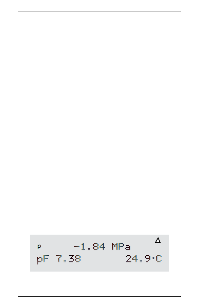
This is the Main menu, displaying the water potential in both MegaPascals (MPa) and pF, and the sample temperature in◦C. In order to
provide the most accurate readings, WP4C should ideally be allowed
a warm-up period of 15 to 30 minutes after turning it on. When you
insert a sample into the chamber drawer and turn the drawer knob
to the READ position, the instrument will begin the read cycle to
measure the water potential of your sample.
3.5 Portability
On occasion you may want to take water potential measurements in
the field where it is not feasible to take samples and return to the
lab. The following is a procedure for powering your WP4C using
your vehicle as a power source at sites where AC power is not readily
available.
1. Purchase a portable power inverter that plugs into the 12 V
output (cigarette lighter) of your vehicle. The inverter should
have a continuous output of at least 140 Watts.
9

3 GETTING STARTED WP4C
2. Place the WP4C on a level surface. Care should be taken to
minimize temperature gradients that may affect the instrument
while in the field. A Styrofoam box, for example, will help
minimize temperature effects.
3. Plug the 12-volt inverter to the 12-volt output of the vehicle,
or directly to the battery itself.
4. Plug the WP4C to the inverter, and turn it on. When the
instrument is on, it draws up to 1 amp. Check the rating of
your battery if you want to know how long it will power the
instrument (for example, if your battery is rated for 60 amp
hours, it will work for 60 hours when the vehicle is not running.
5. Allow the instrument to warm up for 15 to 30 minutes as you
would in the lab. Check the calibration of the instrument before
proceeding with reading.
10

WP4C 4 THE MENUS
4 The Menus
4.1 The Main Menu
Every time you turn on your WP4C, it will open to this screen. If
this screen does not appear, refer to Chapter 12 for troubleshooting
instructions. The water potential and sample temperature displays
on the screen. On each side of the LCD there are buttons. Each
button performs a different function depending on which mode you
want. Figure 3 provides a description of the modes and options you
may use and the buttons that set them.
Figure 3: Main Menu Screen
4.1.1 Changing Languages
The WP4C comes to you with English as the default on-screen user
language. If you prefer not to use English, you can change it to one
of a variety of other languages: German, French, Spanish, Italian,
Swedish, Danish, Norwegian, Czech, Portuguese, Japanese, Polish or
11

4 THE MENUS WP4C
Finnish. Change languages by pressing the upper right button of
the instrument while it is not reading a sample. You will see the
Language screen with default English.
Press the upper right key again, and the next language option (German) will appear.
Each time you press the right button, the display will scroll to the
next language option. Select the language you prefer and press the
lower left button to exit.
4.1.2 Reading Modes
Precise Mode
When you first turn on the WP4C, it will be in precise mode. The
WP4C repeats sample measurements until successive readings agree
within a preset tolerance (0.03 MPa for Ψ > −40 MPa; otherwise
0.3 MPa). The WP4C always starts in precise mode. To toggle
between the precise, continuous and fast modes, press the top left
button. The display will show a small p, c or f to the left of the
water potential readings.(Figure 4)
12

WP4C 4 THE MENUS
Figure 4: Main Menu with Continuous Mode Enabled
Precise mode ensures a precise water potential value by repeating
measurements on a sample. Typical read times are within 10 to 15
minutes. The green LED blinks until you turn the drawer know to
the OPEN/LOAD position.
Continuous Mode
Continuous mode measures the water potential of your sample continuously until you turn the drawer knob to the OPEN/LOAD position. This can be useful in doing long term monitoring of samples
that take an especially long time to come to vapor equilibrium, such
as plant samples and moist soil samples with water potential > −0.5
MPa. In this mode the WP4C will measure the sample, stop to display the water potential and sample temperature, then begin another
read cycle. Between samples, it will signal you with the green LED
flash, accompanied by the beeper, if enabled. Some find it helpful
to connect their WP4C to a computer while in continuous mode in
order to log and store data over time. For instructions on how to do
this, see Chapter 8.
Fast Mode
In fast mode, the sample is measured only once. Read time is typically 3 to 5 minutes. Readings are less precise, particularly in the
wet range. However, fast mode is recommended for dry soil samples
with water potential < −40 MPa.
13

4 THE MENUS WP4C
4.2 System Configuration
If you press the bottom left button while in the Main menu, it will
bring you to the System Configuration menu. This menu allows you
to make minor system changes.(Figure 5 and 6)
Figure 5: Main Menu Buttons
You can change how the beeper signals after each reading and enter
the calibration menu as well.
Figure 6: System Configuration Menu
Changing the Beeper
When you are reading, the WP4C has two ways of notifying you
when it completes the water potential reading for your sample. It
will notify you with the beeper he beeper and a flashing green LED,
14
WP4C 4 THE MENUS
located on the left front corner of the WP4C case. In fast and precise reading modes, the LED will flash once when a sample is started.
When it is finished the LED will flash continuously until the knob is
moved to the OPEN/LOAD position (if not operating in continuous
mode). You cannot turn off or change the LED flashing functions.
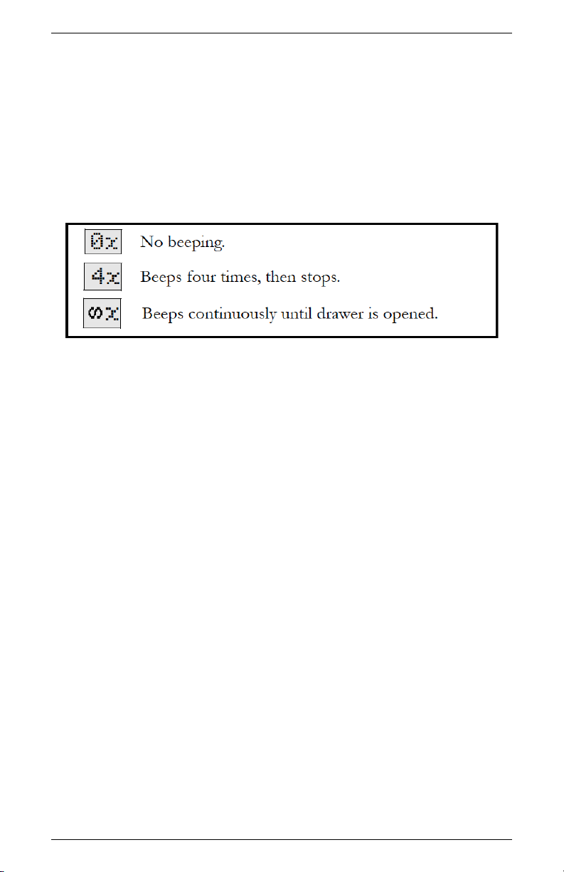
Three different icons represent the three beeper options.(Figure 7)
Figure 7: Definition of Beeper Icons
you can turn the beeper off completely, set it to beep momentarily
(four times) when the sample is finished and then stop, or to beep
continuously until you turn the knob to the OPEN/LOAD position.
After you have adjusted the beeper setting, it will remain as you have
set it until you change it again, and will not be affected by turning
the instrument on or off.
EXIT
You may press the Exit button (the lower left button) to exit back
to the main menu at any time.
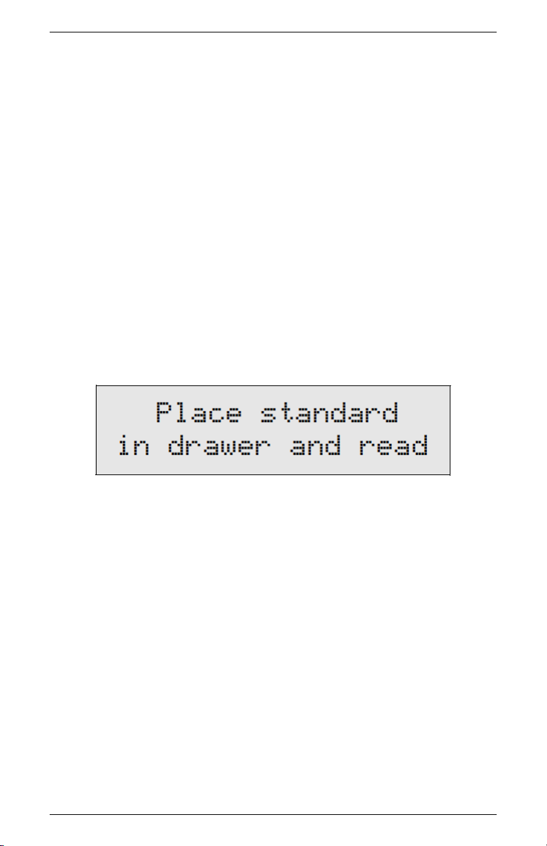
Adjusting Calibration
When you need to adjust calibration, press the upper right button
in the System Configuration menu, and you will be brought to the
Calibration menu. For more details on calibration and how to verify
it, please refer to the Calibration and Verification chapter.
Setting the Temperature
15

4 THE MENUS WP4C
The WP4C gives you the ability to manually set your instrument
sample chamber temperature. To set your instrument sample chamber temperature, press the lower right button next to the “set T” in
the System Con
guration menu. The following screen will appear:
Adjusting the Setpoint Temperature
Use the buttons next to + and − to adjust the target setpoint temperature (displayed in the lower right corner). If you press either
button it adjusts in increments of 0.1◦C.
Note: Holding down the button will rapidly increment the value.
The target setpoint temperature roughly corresponds to the temperature at which you wish the sample to read. Adjust the setpoint
to the temperature that you want, then begin measurements to see
how close your WP4C comes to your desired temperature (this works
best by putting the WP4C in continuous mode). After several samples, it should show consistent temperature readings. At this point,
make any needed adjustment to the setpoint index number to reach
your desired temperature. You will be able to adjust the index number between 15 and 40◦C. If you press the − button after you reach
15◦C, it will disable the temperature control function until you raise
the index number again. When the temperature control is disabled
the display will show ‘off’ in place of the temperature setting.
Important tips with the WP4C
• Before reading, wait for approximately 30 minutes to let the
chamber temperature stabilize after turning it on.
16

WP4C 4 THE MENUS
• Cool samples to a temperature slightly below chamber temperature before starting a reading.
• For slow equilibration samples, such as plant and moist soil
samples (> −0.5 MPa), precise reading mode may yield small
errors. For these types of samples, We recommend you use
continuous mode and log data over time (See Chapter 8) to
determine when equilibrium conditions are reached.
• For samples with very little water holding capacity (i.e. dry
sand samples), small leaks in the sample chamber can cause
water potential to drift down over time. Fast mode is recommended for these samples.
• For best results, run most soil samples in precise mode for best
results.
• Never place a hot or warm sample in a cooled chamber, because
condensation will form inside the chamber, causing errors in
reading.
4.3 Sample Equilibration Screen
To see the temperature difference between your sample and the WP4C,
press the lower right button at the main menu. You can only access
the Temperature Difference screen when the drawer knob is in the
OPEN/LOAD position.
This screen shows the temperature difference between the sample
(Ts) and the chamber block (Tb). This screen allows you to quickly
check if the sample is too hot, which may cause condensation inside
the chamber. Press the lower right button to exit.
17

4 THE MENUS WP4C
Note:) It is important that Ts−Tb is negative in order to prevent
condensation inside the sample chamber.
18

WP4C 5 CALIBRATION AND VERIFICATION
5 Calibration and Verification
5.1 Verification
The WP4C uses the chilled mirror dew point technique for measuring water potential. This is the primary measurement method,
though instrument cleanliness can affect the calibration. We fix the
calibration slope during factory calibration. The user can adjust the
zero offset and calibrate successfully with any solution of known water potential. We recommend using the 0.5 mol/kg KCl verification
standard available from METER.
5.2 Verification Standards
Verification standards are specially prepared salt solutions that have
a specific molality and water potential. The potassium chloride (KCl)
verification standards are accurate, easy to use, and readily available
from METER. Most importantly, they greatly reduce preparation
errors.
The standards are produced under a strict quality assurance regime
and are shelf stable for one year. If for some reason you cannot obtain
METER’s verification standards and need to make a salt solution for
verification, refer to Appendix A.
Note: To avoid inaccurate water activity readings, verification standards should be used once immediately after opening and not stored
in sample cups for repeated use.
5.3 When to Verify Calibration
The calibration of your WP4C should be checked with the KCl standard before each use. It can also be checked by measuring distilled
water, but this is often not a good choice for checking calibration.
When using distilled water, the humidity of the chamber approaches
100% which can cause condensation to occur if the sample is warmer
than the chamber. For batch processing, you should regularly check
19
5 CALIBRATION AND VERIFICATION WP4C
the instrument against the KCl standard. This will alert you to the
possibility of contamination of the unit or shifts in the calibration
from other causes.
5.4 How to Verify and Calibrate the WP4C
Since errors in the calibration value result in errors in all values subsequently measured, care should be taken to do it right.
Checking and Adjusting Calibration
• Press the upper right button in the System Configuration menu
to enter the calibration menu. You will be guided through the
calibration routine beginning with instructions to place your
standard.
• Empty the whole vial of KCl solution into a sample cup and
place it in the WP4C sample drawer. Make sure you calibrate
using the same type of sample cup (plastic or stainless steel)
that you will make subsequent measurements with.
• Carefully slide the drawer closed, being especially careful so the
solution does not splash or spill and contaminate the chamber.
Check to be sure the sample temperature is below chamber
temperature (lower right button).
• Turn the drawer knob to the READ position to make a reading.
When the reading is complete, the following screen will appear:
20
WP4C 5 CALIBRATION AND VERIFICATION
Note: The WP4C will automatically shift to precise sampling
mode for the verification/calibration.
The reading should be within ±0.05 MPa of the correct reading
of the KCl standard at that temperature. At 20◦C this should
be −2.19 MPa. At 25◦C this should be −2.22 MPa.
• If your WP4C is reading within 0.05 MPa of the KCl solution,
press Exit and proceed with reading. If it is not, a change in
calibration may have occurred, or the sensor chamber may be
contaminated. For cleaning instructions, see Chapter 10. After
cleaning, repeat these instructions.
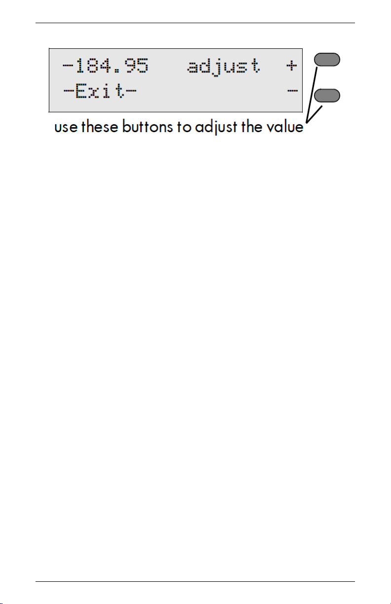
• If, after cleaning, you consistently get readings that differ from
the correct water potential of the KCl by more than ±0.05
MPa, a change in calibration has probably occurred. Press the
upper right button to move the value up, the lower right button to move it down. When it is at the correct value for the
verification standard, press the Exit button. The value will be
stored.
Note: This is the only menu where these buttons can change
the calibration, so you will not hurt anything by pressing these
buttons in other menus.
• Read the KCl standard again in the normal reading mode. It
should read the proper value.
• If after adjusting the calibration and cleaning the chamber you
still are getting incorrect readings when reading the KCl, contact METER at 509-332-5600 for further instructions.
21

6 SAMPLE PREPARATION WP4C
6 Sample Preparation
Your WP4C will continually provide accurate water potential measurements as long as its internal sensors are not contaminated. Careful preparation and loading of samples will lengthen time between
cleanings and will help you avoid downtime and repairs.
6.1 Choosing a Sample Cup
The WP4C comes with two types of samples cups: disposable plastic cups and stainless steel cups. The disposable plastic cups are
adequate for most samples, but are not good for samples in the wet
end. If you are measuring samples with water potential wetter than
−1 MPa, you should use the stainless steel sample cups. You can
also oven dry soil samples directly in the stainless steel cups to determine water content gravimetrically, which is convenient if you are
generating soil moisture characteristic curves. It is important to
note that you must thoroughly clean the stainless steel cups using
deionized water between uses to prevent solutes from contaminating
subsequent samples and causing artificially negative osmotic potential. Finally, if you calibrate the WP4C (see chapter 5), be sure to
calibrate using the same type of sample cup that you intend to use
for subsequent measurements.
6.2 Preparing the Sample
First, place the sample in a disposable sample cup, completely covering the bottom of the cup, if possible.WP4C may not be able to
accurately measure a sample that does not (or cannot) cover the
bottom of the cup. A larger sample surface area speeds up the reading by shortening the time needed to reach vapor equilibrium. It
also increases instrument accuracy by providing more stable infrared
sample temperature measurements.
Do not fill the sample cup more than half full. Overfilled cups may
contaminate the sensors in the chamber, remember more is not necessarily better.
22
WP4C 6 SAMPLE PREPARATION
Make sure that the rim and outside of the sample cup are clean.
Wipe any excess sample material from the rim of the cup with a clean
tissue. Material left on the rim or the outside of the cup will contaminate the sensor chamber and will be transferred to subsequent
samples. The rim of the cup forms a vapor seal with the sensor block
when the drawer knob is turned to the READ position. Therefore,
any sample material left on the cup rim will be transferred to the
block, preventing this seal and contaminating future samples.
If a sample will be read at some future time, put the sample cup
disposable lid on the cup to restrict water transfer. For short-term
storage (< 3 hours) the cup lid is acceptable. If it will be a long time
before the measurement is made, seal the lid with tape or Parafilm
completely around the cup and lid junction.
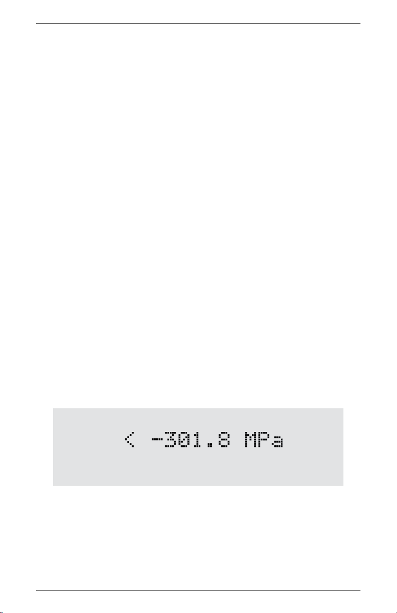
6.3 Dry Samples
R
Samples that have a water potential drier than about −300 MPa
cannot be accurately measured with the WP4C. However, samples
with such dry water potential values are rare. When a sample water
potential value is drier than about −300 MPa, WP4C will display
an error message indicating the lowest reading it could make on that
particular sample. For example, if you were measuring a dry sample
and the following screen appeared:
This screen indicates that the last water potential reading the WP4C
measured on this sample was −301.8 Megapascals. Therefore, the actual water potential of the sample is lower than the instrument can
measure.
23

6 SAMPLE PREPARATION WP4C
6.4 Samples and Temperature
If samples are warmer than the chamber when they are placed in it
(Ts-Tb is a positive number), condensation may occur and moisture
may condense inside the block. In order to prevent this, follow steps
1 and 2.
1. Place your sample in the chamber, slide the drawer closed and
press the lower right button to access the sample temperature
screen and look at the temperature difference. If the sample
temperature is shown to be a positive number, take the sample
out immediately and let it cool on a cold surface with the cup
lid on it to preserve the moisture. Do not cool the sample too
much, or the equilibrium time will be lengthened (ideally the
Ts-Tb will be between −0.5 and 0).
2. After cooling it for a minute or so, place the sample back in
and note the temperature difference. If it is close enough to
the block temperature, turn the knob to the READ position to
begin reading.
There is a linear relationship between the sample dew point temperature and its water potential. The dew point decreases −0.12◦C
per MPa. For example, a very dry sample at −40 MPa can be 4.8
◦
C (−.12 ∗ −40) above the chamber temperature without condensing. A sample at −1 MPa (fairly dry for most soils) can be 0.12◦C
above the chamber temperature without condensing. Therefore, if
you know the general range of your sample water potential, you can
gauge at which temperature it will condense moisture. For samples
that are more than 1◦C below chamber temperature, the WP4C
waits until their temperature increases to 1◦C below chamber temperature to start a reading. Readings are therefore sped up if sample
temperature is just a little below chamber temperature.
24

WP4C 6 SAMPLE PREPARATION
6.5 Measuring Plant Samples
The WP4C can be used to measure the water potential of leaves
and plant material. Please refer to the application note: Measurement of Leaf Water Potential Using the WP4, which can be found
at www.metergroup.com.
6.6 Taking a Reading
Once you have prepared your sample, you are ready to take readings.
Follow steps 1 through 5 to take readings.
1. Turn the sample drawer knob to the OPEN/LOAD position
and pull the drawer open.
2. Place your prepared sample in the drawer. Check the top lip
of the cup to make sure it is free from sample residue (remember, an over-filled sample cup will contaminate the chamber
sensors).
3. Carefully slide the drawer closed, being especially careful if you
have a liquid sample that may splash or spill and contaminate
the chamber.
4. Access the sample temperature menu (press lower right button)
to watch the temperature difference between the sample and
the instrument.
5. Turn the sample drawer knob to the READ position to seal the
sample cup with the chamber. The instrument will beep once,
and the green light will flash once to indicate that the reading
cycle has started. In about 40 seconds, the first measurement
will be displayed.
6.7 How WP4C takes Readings
The WP4C cooled mirror is controlled at the chamber dew point
and its temperature is measured.. When the instrument has finished
its read cycle, the water potential is displayed, accompanied by the
LED flash and beeper (if you have the beeper enabled).
25
6 SAMPLE PREPARATION WP4C
Cautions
• Never leave a sample in your WP4C after a reading has
finished. The sample may spill and contaminate the
instrument chamber if the instrument is accidentally
moved or jolted.
• Never try to move your instrument after loading a sample. Movement may cause the sample material to spill
and contaminate the sample chamber.
• Take special care not to move the sample drawer too
quickly when loading or unloading liquid samples, in
order to avoid spilling.
• If a sample has a temperature that is higher than the
WP4C chamber (Ts-Tb is a positive number), take the
sample out immediately, put a cap on it, and cool it.
Warm samples can cause condensation in the chamber
and adversely affect subsequent readings.
• The physical temperature of the instrument should be
between 5◦C and 40◦C. The WP4C will measure samples between this range quickly and accurately.
• If you are reading and a triangular warning symbol
appears in the top right corner of the display, this indicates that the mirror has become too dirty to give
accurate measurements. You will need to clean the
mirror and chamber before continuing to sample. For
more details about this symbol, please refer to Chapter
12. For cleaning instructions, refer to Chapter 10.
26

WP4C 7 COMPUTER INTERFACE
7 Computer Interface
Your WP4C comes with a RS-232 to USB Serial cable. Using this
cable, you can connect to your WP4C and send water activity data
to a computer for further analysis and storage. The interface is run
through the AquaLink 4 Software or a terminal communication program.
Note: If you computer does not have a USB port, you can use a
USB to RS-232 adapter.
7.1 AquaLink 4 Software
An optional software program, AquaLink 4, is available for use with
your WP4C. AquaLink 4 is a Windows based program designed for
data collection and customized report generation. AquaLink 4 logs
water activity, temperature, time of measurement, and date stamps
along with other information. AquaLink 4 also has sample identification and comment fields that you can use to help annotate the
data your WP4C is gathering.
A 30 day trial USB of this program is attached to the front cover of
this manual. If you are interested in purchasing a license of AquaLink
4, contact METER or your local distributor. On the next page is a
sample picture of the AquaLink 4 program:
27

7 COMPUTER INTERFACE WP4C
Figure 8: AquaLink Screen Shot
7.2 Using a Communication Program
There are several terminal program options. METER has its own
terminal program (DecaTerm) which can be downloaded from:
http://software.metergroup.com/DecaTerm.zip.
Two other options are TeraTerm, which is a free program that can
be found on the Internet and Hyperterminal which came standard
with Windows prior to Windows 7.
To use any of these terminal programs with your WP4C, follow the
instructions for the program with the following settings. Be sure to
power on the WP4C prior to connecting the USB interface cable to
your computer.
• Choose correct Com port
• Set/Verify Com Properties
!
Bits per second 9600
!
8 Databits
28
WP4C 7 COMPUTER INTERFACE
!
No parity
!
1 stop bit
!
Flow control set to none
After successfully connecting the WP4C to your computer and upon
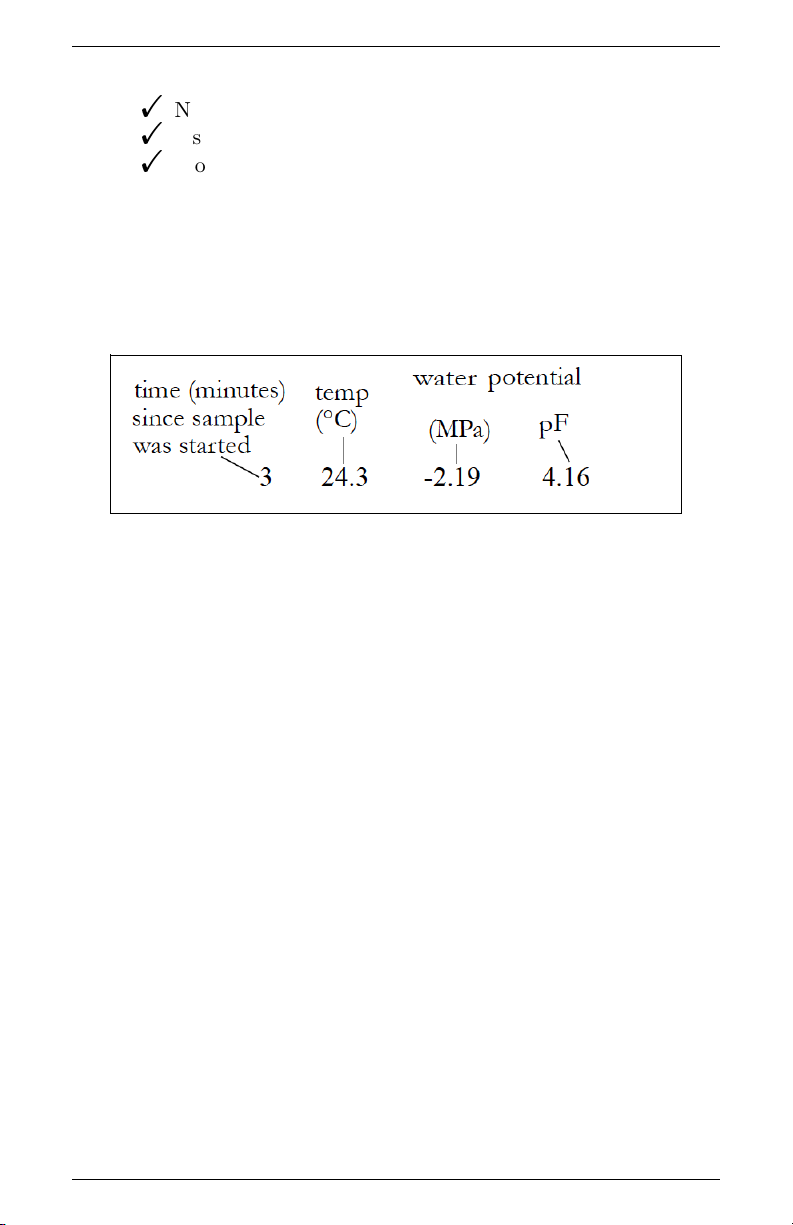
completion of a water activity reading, the data will be displayed in
the terminal program in the format as follows: measurement time
(minutes), sample temperature, and water potential (in both MegaPascals and pF). Figure 9 shows a sample return.
Figure 9: Sample Data Return
29

8 THEORY: WATER POTENTIAL WP4C
8 Theory: Water Potential
8.1 Water Potential
Water potential is defined as the potential energy per unit volume of
water in a sample. The total water potential of a sample is the sum of
four component potentials: gravitational, matric, osmotic, and pressure. Gravitational potential depends on the position of the water
in a gravitational field. Matric potential depends on the adsorptive
forces binding water to a matrix. Osmotic potential depends on the
concentration of dissolved substance in the water. Pressure potential
depends on the hydrostatic or pneumatic pressure on the water.
The WP4C measures the sum of the osmotic and matric potentials in
a sample. Often one or the other of these potentials will be the dominant factor in determining the total potential. For example, solutions
like the KCl calibration standard have only an osmotic component.
Soils bind water mainly through matric forces, and therefore have
mainly a matric component (though salt-affected soils can have a
significant osmotic component).
8.2 Measuring Water Potential
The water potential of a solid or liquid sample can be found by
relating the sample water potential reading to the vapor pressure of
air in equilibrium with the sample. The relation ship between the
sample water potential (Ψ) and the vapor pressure of the air is:
RT
Ψ =
M
where p is the vapor pressure of the air, pois the saturation vapor
pressure at sample temperature, R is the gas constant (8.31 J/mol
K), T is the Kelvin temperature of the sample, and M is the molecular mass of water. The vapor pressure of the air can be measured
using a chilled mirror, and pois computed from sample temperature.
The WP4C measures water potential by equilibrating the liquid
phase water of the sample with the vapor phase water in the headspace
30
∗ ln
p
p
o
(1)

WP4C 8 THEORY: WATER POTENTIAL
of a closed chamber, then measuring the vapor pressure of that
headspace. In the WP4C, a sample is placed in a sample cup, which
is sealed against a sensor block. Inside the sensor block is a fan, a
dew point sensor, a temperature sensor, and an infrared thermometer. The dew point sensor measures the dew point temperature of
the air, and the infrared thermometer measures the sample temperature. The purpose of the fan is to speed equilibrium and to control
the boundary layer conductance of the dew point sensor.
From these measurements, the WP4C computes the vapor pressure
of the air in the headspace as the saturation vapor pressure at dew
point temperature. When the water potential of the sample and the
headspace air are in equilibrium, the measurement of the headspace
vapor pressure and sample temperature (from which saturation vapor pressure is calculated) gives the water potential of the sample.
In addition to equilibrium between the liquid phase water in the
sample and the vapor phase, the internal equilibrium of the sample
itself is important. If the sample is not at internal equilibrium, one
might measure a steady vapor pressure (over the period of measurement) which is not the true water potential of the sample.
8.3 Effect of Temperature on Water Potential
Temperature plays a critical role in water potential determinations.
Most critical is the measurement of the difference between sample
and dew point temperature. If this temperature difference were in
error by 1◦C, an error of 8 MPa would result. In order for water
potential measurements to be accurate to 0.05 MPa, temperature
difference measurements need to be accurate to 0.006◦C.
The WP4C infrared thermometer measures the difference in temperature between the sample and the block. It is carefully calibrated
to minimize temperature errors, but achieving 0.006◦C accuracy is
difficult when temperature differences are large. Best accuracy is
therefore obtained when the sample is near chamber temperature.
Another effect of temperature on water potential occurs with samples
31

8 THEORY: WATER POTENTIAL WP4C
that are near saturation (like many soil samples). A sample that is
close to 0.00 MPa and is only slightly warmer than the sensor block
will condense water within the block. This will cause errors in the
measurement, and in subsequent measurements until the condensation disappears. The Ts-Tb function helps the user ensure that the
sample will not condense on the sensor block.
8.4 Estimating Osmotic Potential
The WP4C measures the sum of osmotic and matric potential. An
approximate value for the osmotic potential can be found by measuring the electrical conductivity (EC) of the saturation extract of
the soil. The osmotic potential of the saturation extract is computed
from:
Ψos(MP a) = −0.036EC(dS/m) (2)
The osmotic component of the water potential is then computed
from:
Ψ = Ψos(
where θ is the volumetric water content of the sample and θsis the
volumetric water content at saturation. The matric potential is the
total potential minus the osmotic.
θ
s
) (3)
θ
32

WP4C 9 CLEANING AND MAINTENANCE
9 Cleaning and Maintenance
The accuracy of your WP4C is vitally dependent on keeping your
instrument clean. Dust and sample debris can contaminate the sampling chamber and must therefore be regularly cleaned out. To clean
your instrument, carefully follow these instructions. Your instrument ships with a cleaning kit that should last one year with regular
cleanings. METER has additional cleaning kits available for purchase with supplies to clean your WP4C.
R
Note: Kimwipe
ideal for cleaning because they do not leave much of a lint residue
like most tissues. They also do not have any other compounds in the
tissue that may contaminate the sensors in the WP4C block. Never
use cotton swabs to clean the block sensors. Most cotton swabs contain adhesives and other compounds that are released and transferred
to the mirror and other surfaces, contaminating them.
are included in the WP4C Cleaning Kit. They are
9.1 Accessing the Block
1. Unplug your WP4C
2. Remove the case lid screw located on the back panel. Carefully
remove the lid by pulling the back of the lid upward and then
sliding the lid back (away from the front of the case) and off.
3. Unscrew the two thumbscrews that secure the sensor block.
4. Unplug the cable with the 20-pin socket that attaches the block
to the main circuit board by releasing the two locking levers
that are on either side of the socket.
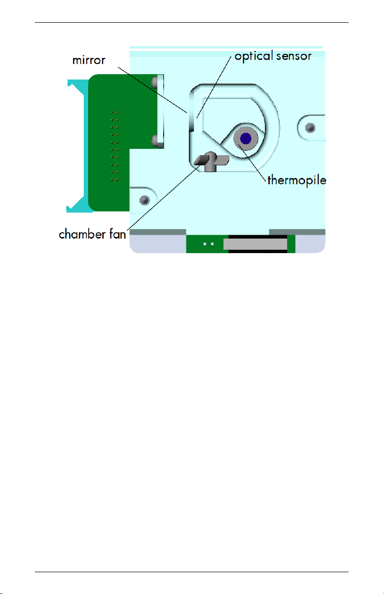
5. Carefully lift the block straight up from its mount. Turn the
block over to expose the chamber cavity as shown in the illustration:
33
9 CLEANING AND MAINTENANCE WP4C
Figure 10: View of Inside Block
9.2 Cleaning Procedure
Cleaning your WP4C is a multi-step procedure which involves washing, rinsing, and drying for each specific area as outlined below:
1. Cleaning the Inside Chamber
Note: Be extremely careful not to damage the fan blades in the
chamber. The fan blades are very fragile; if one of them breaks,
your instrument will not work properly. Take extra care when
cleaning this portion.
(a) Remove any debris that may have collected within or
around the sample chamber.
(b) Wrap a new Kimwipe around the end of the thin plas-
tic rod (spatula) and moisten it with isopropyl alcohol or
cleaning solution.
Note: Do not dip a used Kimwipe into your container
34

WP4C 9 CLEANING AND MAINTENANCE
of IPA or cleaning solution (the IPA or cleaning solution
will become contaminated).
(c) WASH–Clean all surface edges of the samples chamber in-
cluding the edge where the sample cup seals to the chamber block. You may need to replace the Kimwipe if it
becomes too dirty during this process.
(d) RINSE–Repeat steps b and c using new Kimwipes with
deionized water.
(e) DRY–Repeat steps b and c using new, dry Kimwipes to
help remove any moisture remaining from the cleaning.
(f) Visually inspect the sample chamber for cleanliness. Clean
again if necessary.
Note: Do not reuse Kimwipes.
2. Cleaning the Mirror
Note: Wash hands with soap and water (to prevent oils from
contaminating the Kimwipe tissue and being transferred to the
mirror).
(a) Wrap a NEW Kimwipe around the end of the thin plas-
tic rod (spatula) and moisten it with isopropyl alcohol or
cleaning solution.
(b) WASH–Carefully clean the mirror with the moist Kimwipe.
(c) RINSE–Repeat steps b and c using new Kimwipes with
deionized water.
(d) DRY–Repeat steps b and c using new, dry Kimwipes to
help remove any moisture remaining from the cleaning.
(e) Visually inspect the mirror for cleanliness. Re-clean if
necessary. Note: Do not reuse Kimwipes.
3. Cleaning the Optical Sensor
You will probably clean the optical sensor while you are cleaning the mirror, since they face each other in a very small gap.
35

9 CLEANING AND MAINTENANCE WP4C
Clean it in the same manner as described above for the mirror.
4. Cleaning the Thermopile
(a) Wrap a new Kimwipe around the end of the thin plas-
tic rod (spatula) and moisten it with isopropyl alcohol or
cleaning solution.
(b) WASH–Swipe the moistened Kimwipe across thermopile.
(A single swipe is usually sufficient to remove contaminants.)
(c) RINSE–Repeat steps a-b using new Kimwipes moistened
with deionized water instead of cleaning solution.
(d) DRY–Repeat steps a-b but use a new, dry Kimwipe to
help remove any moisture remaining from the cleaning.
(e) Visually inspect the thermopile for cleanliness. This sen-
sor must be free of all dirt and lint. Re-clean if necessary.
5. Inside Case
(a) Clean the sample drawer and drawer base as described
above for the thermopile. Remove any debris that may
have collected inside the case.
(b) Check once more to make sure there is no contamination
of the sample chamber cavity.
(c) Replace the block, and insert the ribbon cable socket into
to the 20-pin plug on the block. Lock it in place with the
locking levers.
(d) Screw the thumb-screws on the block back in until they
are hand-tight.
(e) Replace the case lid and secure the lid screw.
6. Connect the WP4C power cord.
36

WP4C 9 CLEANING AND MAINTENANCE
9.3 Checking Calibration
After you have cleaned the chamber and other parts of your WP4C, it
is important to check the instrument performance in order to correct
for any calibration change that may have occurred during cleaning
procedures.
Check the calibration of your instrument by measuring the water
potential of the KCl standard. If a change has occurred, refer to
chapter 5 for directions on how to recalibrate. If, after adjusting
calibration your instrument is still not reading samples correctly,
contact METER for technical support.
37

10 REPAIR INSTRUCTIONS WP4C
10 Repair Instructions
If your WP4C ever needs to be sent in for service or repair, call METER at 509-332-5600 or fax us at 509-332-5158. We will ask you for
your address, phone number, and serial number. For non-warranty
repairs, we will also ask for a payment method (such as a purchase
order or credit card number), a repair budget, and billing address.
Note: If you purchased your WP4C from one of our international
distributors, please contact them before contacting METER. They
may be able to provide you with local service and help you remedy
the problem.
10.1 Shipping Directions
When you ship your instrument back to us, please include with it a
document with the complete shipping address, name and department
of the person responsible for the instrument, and (most importantly)
a description of the problem. This information will better help our
technicians and our shipping department to expedite repair on your
instrument and ship it back to you in good time.
All WP4Cs returning to METER for servicing must be accompanied with a Return Material Authorization (RMA) form. Prior to
shipping the instrument, please contact a METER customer support
representative to obtain an RMA.
Follow steps 1 through 6 to successfully and safely ship your instrument back to us.
1. If possible, ship your WP4C back in its original cardboard box
with foam inserts. If this is not possible, use a box that has
at least four inches of space between your instrument and each
wall of the box. If you are not using the foam inserts, pack
the box moderately tight with packing material, like styrofoam
peanuts
2. Put your instrument in a plastic bag to avoid disfiguring marks
from the packaging.
38

WP4C 10 REPAIR INSTRUCTIONS
3. Do not ship your WP4C to us with the power cord; we have
plenty here to use with your instrument, and it may damage
the instrument in shipment.
4. Please review the RMA form and verify the ship to and bill to
information, contact name, and problem description. If anything is incorrect, please contact a METER representative.
5. Tape the box in both directions so it will not break open in
shipment.
6. Include the RMA number in the attention line on the shipping
label.
Ship to:
METER Group, Inc.
ATTN: RMA (insert your RMA #)
2365 NE Hopkins Court
Pullman, WA 99163
10.2 Repair Costs
Manufacturers defects and instruments within the one-year warranty
will be repaired at no cost. For non-warranty repairs (including
cleanings for instruments in their warranty period), costs for parts,
labor, and shipping will be billed to you. We have a minimum repair
charge, and an extra fee will be charged for rush work. METER will
provide an estimated repair cost, if requested.
10.3 Loaner Service
METER has loaner instruments to keep you measuring water activity
while your instrument is being serviced. If your WP4C is still under
calibration warranty or you have a service plan with your instrument,
there is no charge for the loaner service.
39

11 TROUBLESHOOTING WP4C
11 Troubleshooting
WP4C is a high performance instrument, designed to have low maintenance and few problems if used with care. Unfortunately, sometimes even the best operators using the best instruments encounter
technical difficulties. Here is a list of some problems that may occur. If you have encountered a problem that is not addressed here,
or if these remedies still do not resolve your problem, contact METER at 509-332-5600 (for those outside the US). If purchased from
a distributor, please contact the distributor for assistance first.
11.1 Problems and Solutions
The following table is a brief guide to help you quickly define solutions to your problems. For more detailed descriptions of these
problems and their solutions, see the explanations below the table.
Table 1: Troubleshooting Quick Guide
If this problem occurs: Refer to:
WP4C does not turn on Problem #1
Long Read Time Problem #2
Readings on KCl standards are too high/low to
adjust
Reading < −301.8 MPa Problem #4
Triangle appears in upper right corner Problem #5
“Block Failure” appears on screen after turning on
WP4C
“Set T” option no longer appears on System Configuration menu
1. PROBLEM
WP4C does not turn on.
SOLUTIONS:
40
Problem #3
Problem #6
Problem #7

WP4C 11 TROUBLESHOOTING
• Check to make sure your power cord is securely attached to the
back of the instrument and the power outlet.
• A power sure may have caused a fuse to blow. Follow steps 1
through 5 to change the fuses.
1. Unplug the power cord from the wall and the instrument.
2. Locate the panel where the power cord plugs in. The fuse
box is on the right side of that panel. Press in on the
release tab and pull the fuse-holder out.
3. Pull the broken fuse(s) out and replace with a 2.0 Amp
250 V fuse. Caution: Do not use any other kind of fuse
or you will risk damage to your instrument and void your
warranty.
4. Replace the fuse-holder and push it into the fuse-well until
the release tab snaps into place.
5. Reconnect the power cord and turn your instrument on.
If the fuse blows again, a failed component may be causing the problem. Contact METER to make arrangements
for repairs if your problem persists.
2. PROBLEM:
Readings are slow or inconsistent.
SOLUTION:
• The sample chamber may be dirty. Refer to Chapter 10 of the
manual for directions on cleaning the sample chamber.
• Some samples absorb or desorb moisture very slowly, causing
measurements to take longer than usual, and nothing can be
done to speed up the process. Refer to Chapter 6 for further
explanation.
• The fan blade inside the block chamber may be broken. If even
the KCl standard takes a long time to read, and the sample
chamber is clean, you may have a broken or bent chamber
41

11 TROUBLESHOOTING WP4C
fan blade. This is especially likely if you have just cleaned
the chamber. If you suspect this may have happened, contact
METER for details on replacement.
3. PROBLEM:
Water potential readings on KCl standards are too high or low and
a calibration adjustment cannot be made any higher or lower.
SOLUTIONS:
• The thermopile in your chamber, which measures sample temperature, may have become contaminated. Refer to Chapter
10 for directions on cleaning.
• If you are not using METER’s KCl verification standards, high
readings may indicate that the salt solution you are using is
not in equilibrium.
4. PROBLEM:
Message on screen displays the following(example):
SOLUTION:
• The sample is too dry for the instrument to read accurately. If
your sample has a water potential that is above the detection
limits of the instrument, this message will come up. Essentially,
it means that there is not enough sample moisture to condense
on the mirror and provide a reading.
• The mirror may be dirty. Try cleaning the mirror and chamber
and measuring the sample again.
42

WP4C 11 TROUBLESHOOTING
5. PROBLEM:
A small triangle appears in the upper right corner after reading:
SOLUTION:
The mirror needs to be cleaned, along with the rest of the sample
chamber, until it disappears. This triangle is a mirror performance
indicator. When the WP4C senses that the mirror performance has
dropped to unacceptable levels, it will display the triangular warning
sign after measuring the sample. When this appears, you should stop
sampling and clean the chamber. If the triangle is still on the screen
after cleaning, the mirror is most likely still dirty and you will need
to clean it until the triangle disappears.
6. PROBLEM:
“Block failure” message appears on screen.
SOLUTION:
• The block is not plugged in to the motherboard. Open the
case and check to make sure that the small ribbon cable that
connects the block to the motherboard is snapped and locked
in place.
• One or more components has failed on the block circuit board.
43

11 TROUBLESHOOTING WP4C
If the block is properly plugged in to the motherboard and this
message appears, it is likely that one or more of the components have failed on the block circuit board.
7. PROBLEM:
The “Set T” option does not appear anymore in the WP4C System
Configuration menu.
SOLUTION:
The temperature control module inside the WP4C is broken or not
functioning correctly. When the instrument senses that there is a
problem with the temperature control module, it removes that function as an option to the user as a precaution. Contact METER for
service information.
11.2 Sensor Performance Screen
If, after cleaning your instrument and reviewing the troubleshooting
items, you have reason to believe that one of the components of
your WP4C may be causing measurement error, you can access a
screen that will display values for component performance. Access
this screen by holding down the lower right button while turning
on the instrument. After it initializes, it will beep and come to the
Performance Evaluation screen.
44
WP4C 11 TROUBLESHOOTING
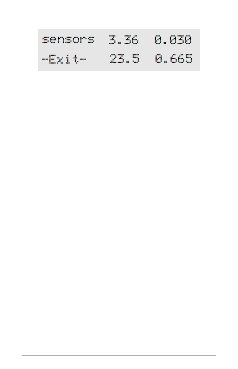
The Performance Evaluation screen gives you four values. The top
left value is the value the thermocouple is reading. It is basically the
difference in temperature between the block and the mirror. If this
is zero, there is something wrong with the thermocouple. The top
right value is the value read by the thermopile, which is the temperature difference between the block and what it “sees” below it (the
sample, when reading). This value is variable, but should never be
zero. The bottom left value is the block temperature. This value
should be around ambient temperature.
The bottom right value is the mirror reflectance voltage, in units
of volts. This value should normally be around 0.5 or above, but if
it drops below 0.3, there is something wrong.
You cannot change anything in this screen, but it will indicate component performance. If you notice that any of these values are not
what they should be, contact METER Support for further instruction. Press the button next to Exit to get back to the main menu.
45

12 FURTHER READING WP4C
12 Further Reading
References:
Brye, K.R., (2003). Long-term effects of cultivation on particle size
and water-retention characteristics determined using wetting curves.
Soil Science Society of America 168:7 459-468.
Campbell, E.C., G.S. Campbell, and W.K. Barlow., (1973). A dew
point hygrometer for water potential measurement. Agric. Meteor.
12:113-121.
G.W. Gee, M.D. Campbell, G.S. Campbell, and J.H. Campbell.,
(1992). Rapid measurement of low soil water potentials using a water activity meter. Soil Science Society of America 56:4 1068-1070.
Papendick, R.I. and G.S. Campbell., (1980). Theory and measurement of water potential. in Water Potential Relations in Soil Microbiology. Soil Science Society of America. Madison, Wisconsin. pp.
1-22.
12.1 Application Notes
The following WP4C application notes are available from METER
by request and from our website under the education tab, choose
WP4C.
• Generating a Soil Moisture Characteristic with the WP4C.
• Measuring Leaf Water Potential using the WP4C.
• Field Portability Instructions for the WP4C.
• Water Potential: The Key to Successful Seed Priming.
• Seed Longevity in Storage is Enhanced by Controlling Water
Activity.
46

WP4C 12 FURTHER READING
• Classification of Expansive Soils using the WP4C Dew point
PotentiaMeter
47

13 APPENDIX A WP4C
13 Appendix A
13.1 Preparing Salt Solutions
Following is a table showing the water potential at given concentrations of NaCl and KCl at 20◦C.
Table 2: Water Potential of NaCl and KCl in Megapascals (MPa)
Concentration
(Moles/kg)
0.05 −0.232 −0.232
0.10 −0.454 −0.452
0.20 −0.901 −0.888
0.30 −1.349 −1.326
0.40 −1.793 −1.760
0.50 −2.242 −2.190
0.60 −2.699 −2.622
0.70 −3.159 −3.061
0.80 −3.618 −3.501
0.90 −4.087 −3.931
1.00 −4.558 −4.372
NaCl KCl
48

WP4C 14 APPENDIX B
14 Appendix B
Temperature Correction
of METER’s Verification Standards
Table 3: Water Activity of Selected Salt Solutions
0.50 2.33 6.00 8.57 13.41 17.18
Temp. H2O
(◦C)
15.0 1.000 0.984 0.923 0.761 0.492 0.238 0.140
20.0 1.000 0.984 0.922 0.760 0.496 0.245 0.145
25.0 1.000 0.984 0.920 0.760 0.500 0.250 0.150
30.0 1.000 0.984 0.920 0.760 0.504 0.255 0.155
35.0 1.000 0.984 0.920 0.760 0.508 0.261 0.160
40.0 1.000 0.984 0.921 0.760 0.512 0.266 0.165
50.0 1.000 0.984 0.894 0.740 0.517 0.275 0.172
mol/kg mol/kg mol/kg mol/kg mol/kg mol/kg
KCL NaCL NaCL LiCl LiCl LiCl
49

15 DECLARATION OF CONFORMITY WP4C
15 Declaration of Conformity
Application of Council Directive: 2004/108/EC and 2011/65/EU
Standards to which conformity is
declared:
Manufacturer’s Name: METER Group, Inc USA
Type of Equipment: Dew Point PotentiaMeter
Model Number: WP4C
Year of First Manufacture: 2010
This is to certify that the Dew Point PotentiaMeter, manufactured by
METER Group, Inc. USA, a corporation based in Pullman, Washington, USA meets or exceeds the standards for CE compliance as
per the Council Directives noted above. All instruments are built at
the factory at METER and pertinent testing documentation is freely
available for verification.
EN 61326-1:2013 and
EN 50581:2012
2365 NE Hopkins Ct.
Pullman, WA 99163
USA
50

WP4C 16 CERTIFICATE OF TRACEABILITY
16 Certificate of Traceability
METER Group, Inc.
2365 NE Hopkins Court
Pullman WA 99163 USA
Tel: 509-332-5600
Fax: 509-332-5158
support.environment@metergroup.com
This NIST seal certifies that METER Group, Inc. manufactures all
WP4C Dew Point PotentiaMeters according to temperature standards with calibration traceable to the National Institute of Standards and Technology (NIST).
51

Index
Accessories, 7
Application Notes, 46
AquaLink 4 Software, 27
Beeper, 14, 44
Block Failure, 40, 43
Block Sensors, 33
Buttons
Menu Selection, 11
C for Continuous Mode, 13
Calibration
Changes In, 19
Checking, 37
Drift, 19
Menu, 15
Steps, 20
When to Check, 19
Cautions, 26
CE Compliance, 50
Certificate of Traceability, 51
Chilled Mirror Technique, 5
Cleaning, 33
Inside Case, 36
Inside Chamber, 34
Optical Sensor, 35
Sensor Block, 33
Thermopile, 36
Components, 7
Computer Interface, 27
Contact Information, 1
Cotton Swabs
Not for Cleaning, 33
Customer Support, 1
DecaTerm Program, 28
Declaration of Conformity, 50
Dirty Mirror Indicator, 26
Distilled Water, 19
Dry Samples, 23, 42
Dry Water Potential, 23
Email, 1, 51
Error Messages, 40
Exit, 15
Fan
Inside Sample Chamber, 31
Fax Number, ii
Features, 8
Field Measurements, 9
Further Reading, 46
Fuse
Changing, 41
Gravitational Potential, 30
Hyperterminal, 28
KCl Standards, 19
Languages
Changing, 11
Czech, 11
Danish, 11
Finnish, 12
French, 11
German, 11
Italian, 11
Japanese, 11
Norwegian, 11
Polish, 11
Portuguese, 11
52

WP4C INDEX
Spanish, 11
Swedish, 11
Leaf
Measuring Water Potential in
Continuous Mode, 13
LED, 14, 44
Linear Offset
Adjusting for, 20
Loaner Service, 39
Location
for Reading, 7
Main Menu, 8, 11
Maintenance, 33
Matric Potential, 30
Menu
Main Menu, 11
System Configuration, 14
Molality
Verification Standards, 19
Osmotic Potential, 30, 32
Peltier Cooler, 5
Phone Number, ii
Plant Samples, 25
Portability, 9
Preparing Salt Solutions, 48
Pressure Potential, 30
Read Time
Affected by Sample Temper-
ature, 24
Long, 40, 41
Reading Modes, 12
Continuous, 13
Fast, 13
Precise, 12
Readings
Cautions, 26
How WP4C Takes, 25
Taking Readings, 25
References, 46
Repair
Costs, 39
Instructions, 38
Shipping, 38
Sample
Dry Water Potential, 23
Not at Room Temperature,
24
Preparation, 22
Slow Water Emitting, 41
Spilling, 26
Too Dry, 42
Too Hot, 26
Sample Cups
Cleaning, 22
Filling, 22
Sealing, 22
Sample Equilibration Screen, 17
Saturated Salts, 48
Seller’s Liability, 2
Sensor Performance Screen, 44
Specifications, 4
Technical Support, 1
Temperature
Effect on Water Potential, 31
Hot Samples, 26
Impact on Readings, 6
Instrument, 26
Samples not at Room Tem-
perature, 24
Setting, 15
Triangle, 40, 43
Troubleshooting, 40
USB
53

INDEX WP4C
Driver, 28
Interface Cable, 27
Vapor Pressure, 30, 31
Verification Standards, 19
Long Read Times for, 42
Water Potential too High/Low,
42
Warm-Up, 10
Warranty, 2
Water Content, 30
vs Water Potential, 30
Water Potential, 30
Definition, 5
Displayed, 8
Equation, 30
Measurement, 30
Theory, 30
WP4C
and Temperature, 6
Chilled Mirror Dew Point Tech-
nique, 5
Important Tips, 16
Measuring Water Potential, 30
Preparing for Operation, 8
Theory, 30
WP4C Readings
Cautions, 26
54
 Loading...