

Page 1

WP4C
Page 2

13588-06
4.30.2019
TABLE OF CONTENTS
1. Introduction ..............................................................................................1
2. Operation ...................................................................................................2
2.1 Installation ................................................................................................2
2.2 Preparing Samples .....................................................................................3
2.3 Checking Sample Temperature ..................................................................4
2.4 Taking a Reading ........................................................................................ 4
3. System .........................................................................................................6
3.1 Specifications ............................................................................................6
3.2 Components ..............................................................................................8
3.2.1 Sample Chamber..............................................................................9
3.2.2 LED ................................................................................................ 10
3.2.3 Buttons .......................................................................................... 10
3.2.4 Display Screen ............................................................................... 11
3.2.5 Reading Modes .............................................................................. 14
3.2.6 Computer Interface ........................................................................15
3.3 Theory ...................................................................................................... 16
3.3.1 Defining Water Potential ...............................................................16
3.3.2 Measuring Water Potential ............................................................17
4. Service ....................................................................................................... 19
4.1 Calibration ............................................................................................... 19
4.1.1 Verification Standards ................................................................... 19
4.1.2 Calibration Process ........................................................................ 19
4.2 Maintenance ............................................................................................ 21
4.3 Cleaning ................................................................................................... 21
i
Page 3

4.4 Repair ...................................................................................................... 25
4.5 Troubleshooting ....................................................................................... 26
4.6 Customer Support....................................................................................28
4.7 Terms and Conditions ..............................................................................28
Further Reading ..........................................................................................29
Index .................................................................................................................32
ii
Page 4
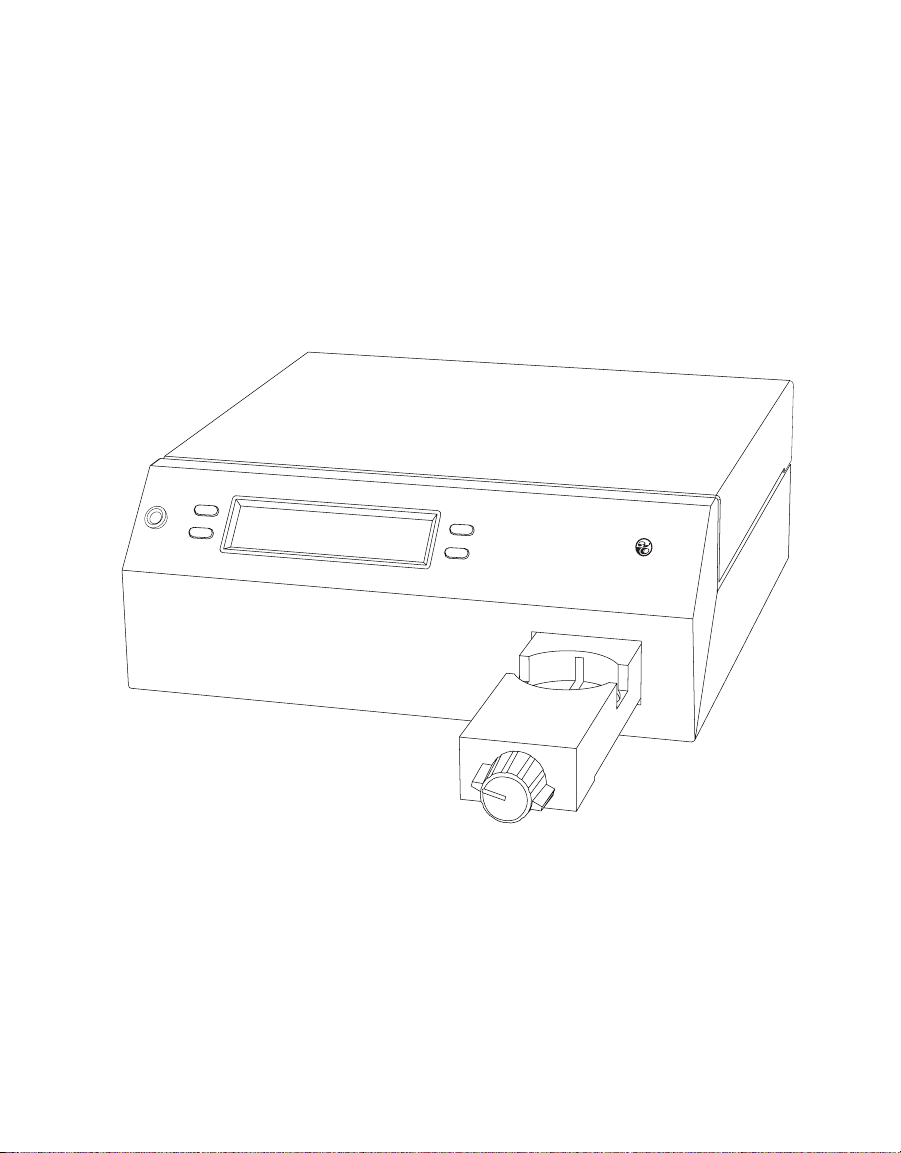
WP4C
Dewpoi nt Potentia Meter
Page 5

1. INTRODUCTION
Thank you for choosing the WP4C Dewpoint PotentiaMeter from METER Group.
WP4C is a fast, accurate, and reliable way to measure water potential using the chilledmirror dew point technique. This manual includes instructions for setting up, calibrating, and
maintaining the WP4C. This manual also explains the basic concepts of water potential.
Verify all WP4C components are included and appear in good condition:
• WP4C unit
• Power cord
• RS-232 to USB cable
• 25 plastic sample cups and lids
• 10 stainless steel sample cups
• 12 vials of 0.50 mol/kg potassium chloride (KCl) verification standard
• Cleaning kit
1
Page 6

OPERATION
2. OPERATION
Please read all instructions before operating the WP4C to ensure it performs to its full
potential.
PRECAUTIONS
METER instruments are built to the highest standards, but misuse, improper protection,
or improper installation may damage the sensor and possibly void the manufacturer’s
warranty. Before setting up the WP4C, follow the recommended installation instructions
and arrange proper protections to safeguard the instrument from damage.
2.1 INSTALLATION
Follow the steps listed in Table 1 to set up the WP4C.
Table 1 Installation
Tools Needed
Preparation
Installation
(continued)
Portable 12-V power inverter (field installation)
Select Clean, Level Location
Select a location where the temperature remains fairly stable to avoid
temperature changes that can affect accuracy (away from air conditioner and
heater vents, open windows, etc.). If in the field, a Styrofoam box, for example,
can help minimize temperature effects.
Observe clean practices to prevent contamination of the sample chamber.
Maintain a level surface to reduce the chance of spilling sample material and
contaminating the sample chamber.
Remove Sample Cup
Pull open the sample drawer by turning the knob to the OPEN/LOAD position.
Remove the empty upside-down disposable sample cup (used to protect the
drawer during shipment) and set aside.
Plug In Instrument
Plug the power cord into the back of the WP4C unit and an outlet. Use only the
supplied power cord.
If in the field, plug the instrument into a 12-V portable power inverter that plugs
into the 12 V output of a vehicle.The inverter should have a continuous output of
at least 140 W.
NOTE: When the instrument is on, it draws up to 1 A. Check the battery rating to determine
how long it will power the instrument (for example, if the battery is rated for 60 Ah, it will
work for 60 h when the vehicle is not running).
WARNING: An incorrect main power voltage can damage the instrument.
Turn the Unit ON.
The ON/OFF switch is located on the lower right corner of the WP4C back panel.
Allow the WP4C a 15- to 30-min warm-up period to ensure accurate readings.
Check the calibration of the instrument (Section4.1).
2
Page 7

WP4C
2.2 PREPARING SAMPLES
Proper sample preparation is important to keep the WP4C internal sensors clean and
achieve repeatable results. Carefully prepare and load samples to lengthen the time
between cleanings and help avoid downtime. Be consistent in sample preparation methods
to obtain reproducible results.
Considerations regarding sample temperature are discussed in Section2.3.
NOTE: Calibrate the WP4C (Section4.1) using the same type of sample cup that will be used for subsequent
measurements.
Follow the steps listed below to prepare samples.
1. Choose an appropriate sample cup.
METER recommends using stainless steel cups because stainless steel cups come to
temperature equilibrium with the sample block more quickly, leading to a more accurate
measurement. Only use disposable plastic cups for dry samples.
NOTE: Soil samples can be oven dried directly in the stainless steel cups to determine water content
gravimetrically, which is convenient if generating soil moisture characteristic curves.
2. Place the sample in the sample cup.
a. Completely cover the bottom of the cup, if possible, to provide enough sample to get
an accurate reading.
The WP4C may not be able to accurately measure a sample that does not (or cannot)
cover the bottom of the cup. A larger sample surface area speeds up the reading by
shortening the time needed to reach vapor equilibrium. It also increases instrument
accuracy by providing more stable infrared sample temperature measurements.
b. Do not fill the sample cup more than half full.
Overfilled cups may contaminate the sensors in the chamber.
3. Wipe any excess sample material from the rim of the cup with a clean KIMWIPES
®
tissue.
Material left on the rim or the outside of the cup will prevent a vapor seal with the
sensor block and will contaminate subsequent samples.
4. If a sample cannot be read immediately, put the disposable sample cup lid on the cup to
restrict water transfer.
For longer term storage, seal the lid by placing tape or Parafilm
®
laboratory film
completely around the cup to lid junction.
Thoroughly clean the stainless steel cups using deionized water between uses to prevent
solutes from contaminating subsequent samples and causing artificially negative osmotic
potential.
The WP4C can be used to measure the water potential of leaves and plant material. Refer
to the application note Easy, accurate measurement of leaf water potential using the WP4C
(metergroup.com/environment/articles/measurement-leaf-water-potential-using-wp4c/).
3
Page 8

OPERATION
2.3 CHECKING SAMPLE TEMPERATURE
For an accurate measurement, the sample temperature (Ts ) should be close to the
sample block temperature (Tb). WP4C displays the temperature difference in the sample
temperature screen.
If a sample is warmer than the sample chamber (Ts-Tb is a positive number), condensation
may occur and moisture may condense inside the block, which will adversely affect readings.
If a sample is colder than the sample block temperature (Ts-Tb is a negative number), the
WP4C will wait to start a reading until its temperature increases to 1 °C below sample block
temperature. The closer the sample temperature is to the sample block temperature (i.e.,
closer to equilibrium), the less time is need for a reading.
To ensure the sample is at the correct temperature, use the following steps.
1. Place the sample in the chamber and close the drawer.
2. Press the lower right button to access the sample temperature screen and view the
temperature difference.
3. If the sample temperature difference is between −0.5 and 0, the sample can be used to
begin a reading (Section2.3).
If the sample temperature difference is a positive number, remove the sample
immediately.
4. Set the sample on a cold surface and cover with the cup lid to preserve the moisture.
Leave for approximately 1 min.
Do not cool the sample too much or the equilibrium time will be lengthened.
5. Place the sample back in the chamber and note the temperature difference again.
If it is between −0.5 and 0, begin the reading (Section2.4).
2.4 TAKING A READING
Observe the following cautions and use the following steps to take a reading.
CAUTIONS
• Ensure that the physical temperature of the WP4C is between 5 °C and 40 °C.
• Do not measure a sample that has a temperature greater than the WP4C chamber
(Section2.3). Remove the sample until it is at room temperature.
• Do not move the sample drawer too quickly when loading or unloading samples to avoid
spilling.
• Never try to move the instrument after a sample is loaded. Movement may cause the
sample material to spill and contaminate the sample chamber.
• Never leave a sample in the WP4C after a reading has finished. The sample may spill and
contaminate the instrument chamber if the instrument is accidentally moved or jolted.
4
Page 9
WP4C
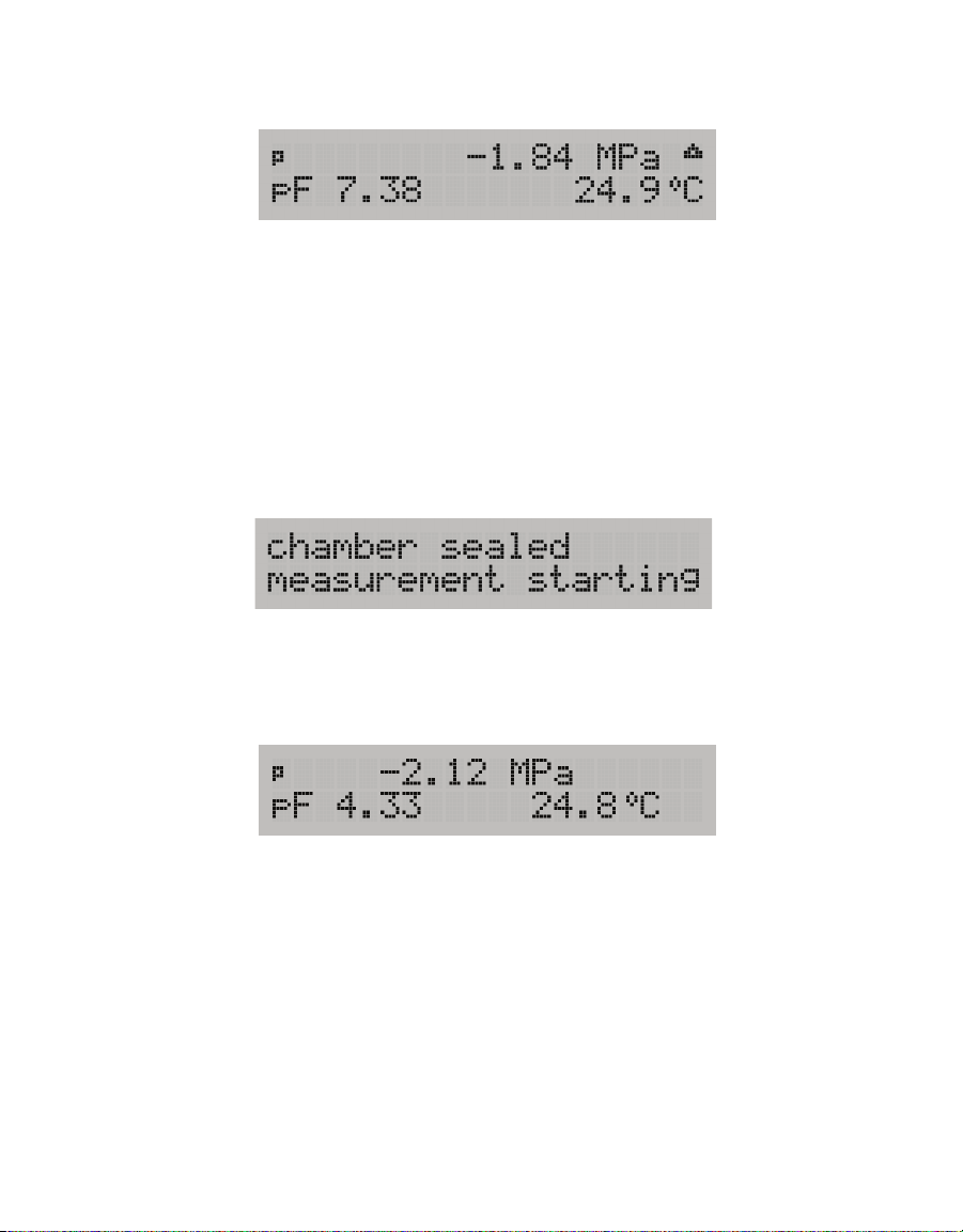
• Consult troubleshooting (Section4.5) if the triangular warning symbol appears in the top
right corner of the display (Figure1).
Figure1 Triangular warning sign
Perform the following steps to take a reading.
1. Turn the drawer knob to OPEN/LOAD and pull the drawer out.
2. Place the sample in the sample drawer and carefully slide the drawer closed to avoid
spilling solution and contaminating the chamber.
3. Check to be sure the sample temperature is below chamber temperature (lower right
button).
4. Turn the drawer knob to the READ position.
A notification that the measurement is starting will appear (Figure2).
Figure2 Measurement starting notification
Values display the initial measurements being taken and the Main screen will update
values throughout the reading. WP4C signals when it reaches the final values by a green
LED flash and an audible notification (if enabled). The WP4C will display the final water
potential and temperature of the sample (Figure3).
Figure3 Results screen
5
Page 10

SYSTEM
3. SYSTEM
This section describes the specifications, components, and theory of the WP4C instrument.
3.1 SPECIFICATIONS
MEASUREMENT SPECIFICATIONS
Water Potential
Range 0 to –300 MPa
Resolution NA
Accuracy ±0.05 MPa from 0 to –5 MPa
1% from –5 to –300 MPa
NOTE: All vapor pressure instruments (including the WP4C) are limited by accuracy in the wet end of the water
potential range. The range of 0 to −5 MPa has an accuracy of ±0.05 MPa. For example, a measurement of −0.1 MPa
has an accuracy of ±50% of the measurement and a measurement of −1 MPa has an accuracy of ±5%. The WP4C will
not measure water potential accurately near field capacity (-0.033 MPa).
Temperature
Range 15-40 °C
Resolution 0.1 °C
Accuracy ±0.2 °C
Read Time
~10–15 min (precise mode)
Soil sample
Plant sample ~20 min
<5 min (fast mode)
NOTE: WP4C will display updated measurements approximately every 5 min until
stopped.
PHYSICAL SPECIFICATIONS
Case Dimensions
Length 24.1 cm (9.5 in)
Width 22.9 cm (9.0 in)
Height 8.9 cm (3.5 in)
Case Material
Powder painted aluminum
6
Page 11

Sample Cup Capacity
15 mL (0.5 oz) full
7 mL (0.25 oz) recommended
Weight
3.2 kg (7.1 lb)
Display
20 x 2 alphanumeric LCD with backlighting
Sensor Types
Chilled-mirror dew point sensor
Infrared temperature sensor
Operating Temperature
Minimum 5 °C
Typical NA
Maximum 40 °C
Data Communications
RS-232A serial
8-data bit ASCII code
9,600 baud, no parity
1 stop bit
WP4C
Interface Cable
Standard RS-232 to USB cable (included)
Power
110–220 VAC
50/60 Hz
COMPLIANCE
Manufactured under ISO 9001:2015
EM ISO/IEC 17050:2010 (CE Mark)
Compatible standard: ASTM D6836-07
7
Page 12
SYSTEM
OPEN/LOAD
READ
LED
Function keys
Sample drawer
LCD screen
WP4C
Dewpoint PotentiaMe ter
3.2 COMPONENTS
The WP4C uses the chilled-mirror dew point technique to measure the water potential of
a sample. In an instrument that uses the dew point technique, the sample is equilibrated
with the headspace of a sealed chamber that contains a mirror and a means of detecting
condensation on the mirror. At equilibrium, the water potential of the air in the chamber is
the same as the water potential of the sample.
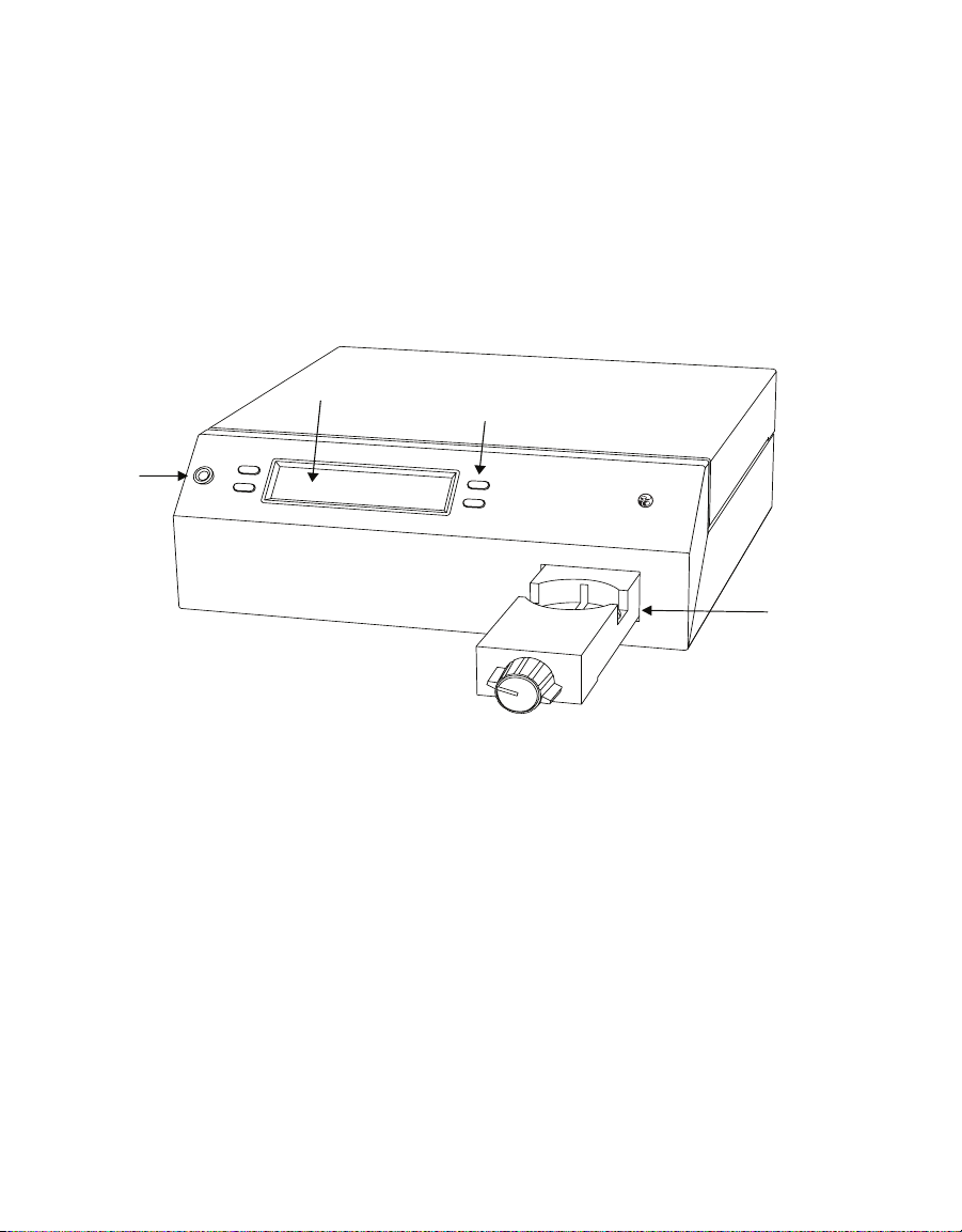
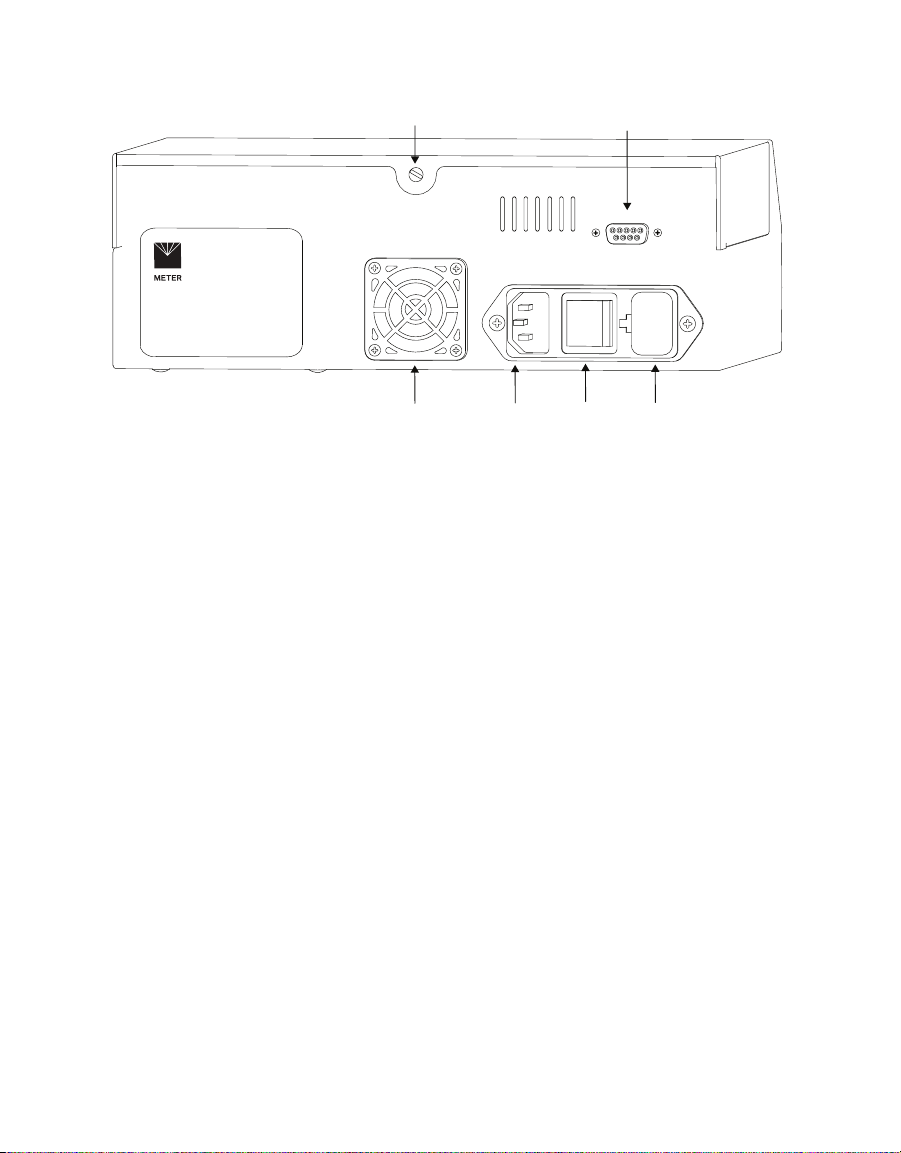
The WP4C main components include the display screen and sample chamber (Figure4 and
Figure5). A power cord and RS-232 communication cable can be plugged into the back of the
unit.
Figure4 Front view
8
Page 13
WP4C
Lidscrew
Fan
Power
cord plug
RS-232 connection
ON/OFF
switch
Fuse well
Figure5 Back view
3.2.1 SAMPLE CHAMBER
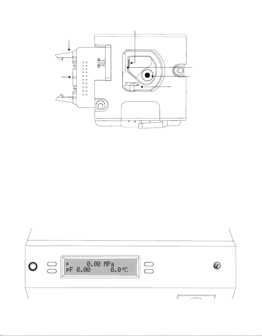
The sample chamber has many components (Figure6). An internal thermoelectric module
equilibrates the sample temperature to the headspace of the chamber.
A thermoelectric (Peltier) cooler controls the mirror temperature. A photoelectric cell detects
the exact point when condensation first appears on the mirror by measuring a reflected
beam of light with a photodetector. The photodetector senses the change in reflectance
when condensation occurs on the mirror. A thermocouple attached to the mirror records the
temperature when condensation occurs.
An internal fan circulates the air within the sample chamber to reduce time to equilibrium.
Both dew point and sample surface temperatures are simultaneously measured, eliminating
the need for complete thermal equilibrium.
9
Page 14
SYSTEM
Optical sensor
Locking levers
Mirror
20-pin socket
Fan
IR thermometer
Figure6 Sample chamber
3.2.2 LED
A flashing green LED, located on the left front corner of the WP4C case, blinks to notify the
user of different settings.
The LED flashes once when a sample reading starts. In Fast and Precise reading modes, the
LED will flash continuously when the sample reading is finished until the sample drawer
knob is moved to the OPEN/LOAD position. The LED settings cannot be changed or turned off.
3.2.3 BUTTONS
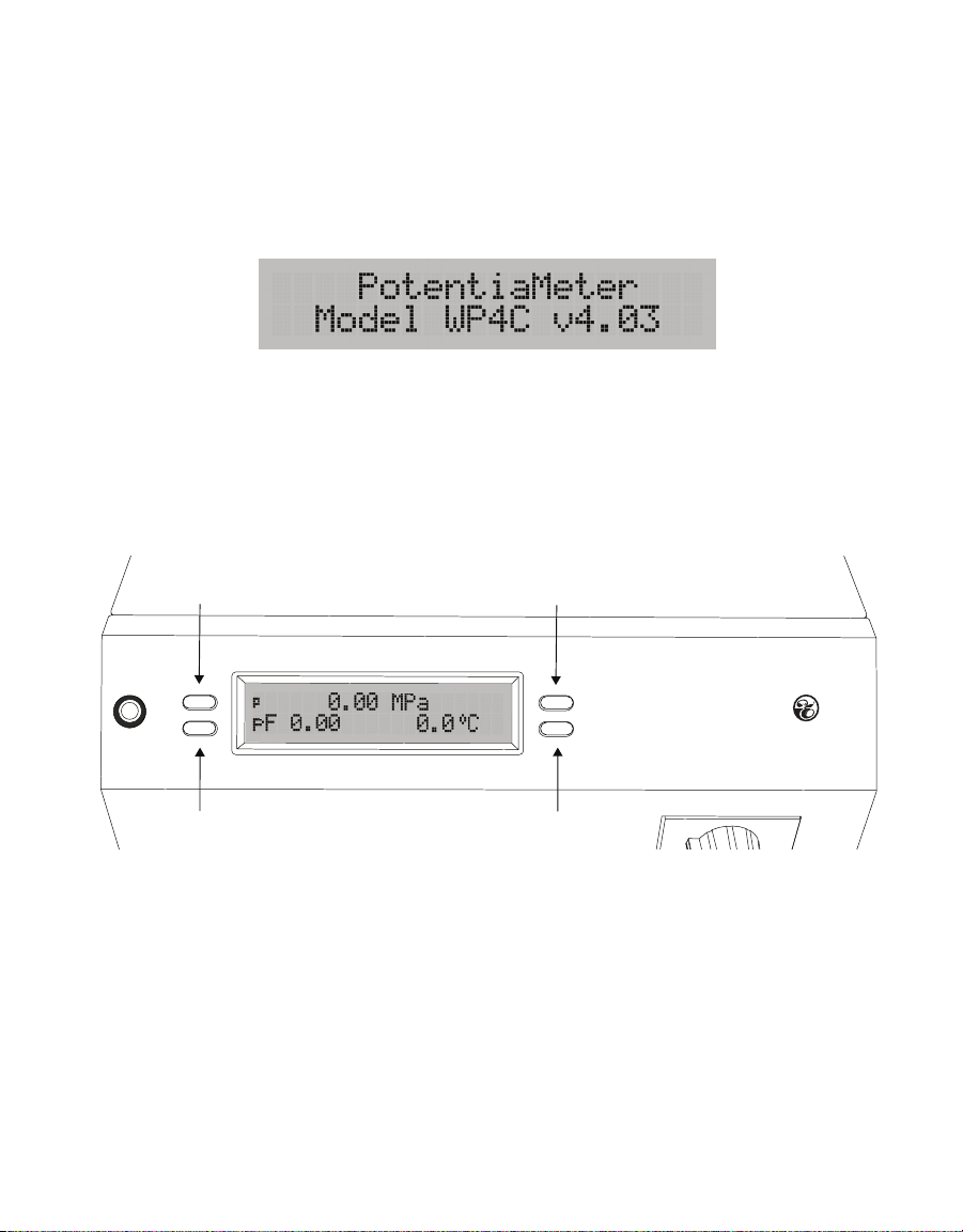
Four buttons flank the LCD screen (Figure7). The function of each button changes
depending on the current screen (Section3.2.4).
WP4C
Dewpo int Po tentia Meter
Figure7 Buttons
10
Page 15
WP4C
3.2.4 DISPLAY SCREEN
The WP4C has five different screens to display data and change settings.
3.2.4.1. MODEL INFORMATION SCREEN
The Model Information screen (Figure8) will appear for approximately 3 s after turning the
WP4C on, immediately followed by the Main screen.
Figure8 Model Information screen
3.2.4.2. MAIN SCREEN
The Main screen (Figure9) displays the water potential in both megapascals and log-scaled
pF values. The sample temperature is displayed in degrees Celsius. The values on this
screen will update during measurements. A small letter in the top left indicates the reading
mode.
Reading mode
System Setup screen Sample Temperature screen
Language screen
WP4C
Dewpo int Po tentiaMeter
Figure9 Main Menu screen and button functions
Pressing the upper left button will change the reading mode (Section3.2.5). The symbol on
the screen will toggle between p, c, or f to indicate if WP4C is reading in Precise, Continuous,
or Fast mode.
Press the upper right button to change the WP4C language (Section3.2.4.3).
Press the lower right button to show sample temperature information (Section3.2.4.4).
Press the lower left button to bring up system setup options (Section3.2.4.5).
NOTE: WP4C will not allow button selections while the unit is reading a sample.
11
Page 16
SYSTEM
3.2.4.3. LANGUAGE SCREEN
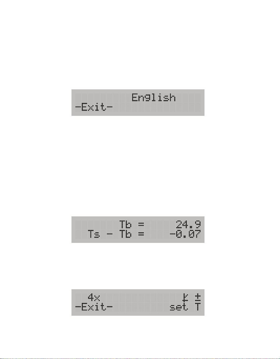
The Language screen shows the current selected language for the unit. English is the WP4C
default on-screen language. The on-screen user language can be changed to any one of the
following languages: German, French, Spanish, Italian, Swedish, Danish, Norwegian, Czech,
Portuguese, Japanese, Polish, or Finnish.
From the Main screen, press the upper right button. The Language screen (Figure10) with
default English will appear. Continue pressing the upper right button to scroll through the
language options. When the preferred language is reached, press the lower left button to exit.
Figure10 English screen
3.2.4.4. SAMPLE TEMPERATURE SCREEN
The Sample Temperature screen (Figure11) displays the sample temperature (Ts) and the
temperature difference between the WP4C sample and the sample block (Ts - Tb). Use this
screen to quickly check if the sample is too hot, which may cause condensation inside the
chamber.
NOTE: It is important that Ts−Tb is negative in order to prevent condensation inside the sample chamber.
From the Main screen, press the lower right button to bring up the Sample Temperature
screen. Press either of the lower buttons to exit.
NOTE: The sample drawer knob must be in the OPEN/LOAD position to access the Sample Temperature screen.
Figure11 Sample Temperature screen
3.2.4.5. SYSTEM SETUP SCREEN
The System Setup screen is used to change how the WP4C signals after each reading, enter
the Calibration Menu, and set the Temperature (set T) (Figure12).
Figure12 System Setup screen
12
Page 17
WP4C
From the Main screen, press the bottom left button to access this menu. Use the buttons to
select the desired setting to configure: audible notification, calibration, and temperature.
Press the upper left button to toggle adjust the audible notification at the end of a reading.
Three icons represent the three options: no notification (0x), beep momentarily before
stopping (4x), or beep continuously until the sample drawer knob is turned to the OPEN/
LOAD position.
NOTE: The audible notification is not changed by turning the instrument off and on.
Press the upper right button to go to start calibration (Section4.1).
Press the lower right button to set WP4C temperature (Section3.2.4.6)
Press the lower left button to exit back to the Main menu at any time.
3.2.4.6. TEMPERATURE SET SCREEN
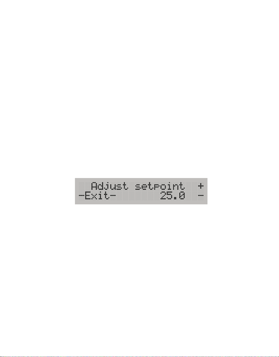
The default temperature of the WP4C sample block temperature is 25 °C. The Temperature
Set screen allows the sample block temperature to be set manually (Figure13). The sample
block temperature roughly corresponds to the temperature needed to read the sample.
To access this screen from the Main menu, press the lower left button, followed by the lower
right button (next to set T) on the System setup screen.
Figure13 Temperature Set screen
The index number can be adjusted between 15 and 40 °C. Use the right buttons next to the +
and − symbols to adjust the sample block temperature value in increments of 0.1 °C.
NOTE: Holding down the button will rapidly increment the value.
The temperature control can be disabled by pressing the − button after reaching 15 °C.
Reenable temperature control by pressing the + button to bringing the sample block
temperature back into its controllable range.
After adjusting the sample block temperature, wait 15 min before taking a measurement to
allow the sample block to reach the new temperature.
3.2.4.7. PERFORMANCE EVALUATION SCREEN
The Performance Evaluation screen needs to be accessed only if one of the components
of the WP4C may be causing a measurement error. Before accessing this screen, ensure
the instrument has been cleaned (Section4.3) and other troubleshooting steps have been
13
Page 18
SYSTEM
reviewed (Section4.5). Values on this screen cannot be changed, but they will indicate
component performance. If any of these values are not what they should be, contact
Customer Support.
To access this screen, hold down the lower right button while turning on the instrument.
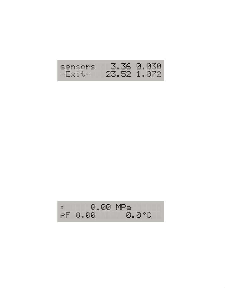
After the instrument initializes, the Performance Evaluation screen will appear, providing
four values (Figure14).
Figure14 Example Performance Evaluation screen
• The top left value is the value the thermocouple is reading—the temperature difference
between the sample block and the mirror. If this is 0, there is something wrong with the
thermocouple.
• The top right value is the value read by the thermopile—the temperature difference
between the sample block and the sample. This value is variable but should never be 0.
• The bottom left value is the sample block temperature. This value should be around
ambient temperature.
• The bottom right value is the mirror reflectance voltage, in volts. This value should normally
be around 0.5 or above, but if it drops below 0.3, there is something wrong.
Press the button next to –Exit– to bring up the Main menu.
3.2.5 READING MODES
WP4C has three reading modes: precise, continuous, or fast. The display will show a small
p, c, or f to the left of the water potential readings (Figure15) indicating which mode is
selected. To change the mode, navigate to the Main screen and press the upper left button.
NOTE: WP4C will not allow button selections while the unit is reading a sample.
Figure15 Main Menu with Continuous mode enabled
PRECISE MODE
Precise mode is the default WP4C mode. WP4C repeats sample measurements until
successive readings agree within a preset tolerance (0.03 MPa for
0.3 MPa). For most accurate results, run most soil samples in Precise mode. Typical read
times are within 10 to 15 min.
14
Ψ > −40 MPa; otherwise
Page 19

WP4C
CONTINUOUS MODE
Continuous mode measures the water potential of the sample continuously until the drawer
knob is turned back to the OPEN/LOAD position. The WP4C will measure the sample, display
the water potential and sample temperature, then begin another read cycle. WP4C will
signal the end of a reading with an LED flash and audible notification (if enabled).
Continuous mode is recommended for samples that take a long time (20 to 30 min) to come
to vapor equilibrium, such as plant samples and wet soil samples with water potential
>−0.5 MPa. METER recommends using Continuous mode and logging data to determine when
equilibrium conditions are reached. It may be helpful to connect the WP4C to a computer
while in Continuous mode in order to log and store data over time (Section3.2.6).
FAST MODE
Fast mode measures the sample once. Read time is typically 3 to 5 min. Readings are less
precise, particularly in the wet range.
Fast mode is recommended for dry soil samples with water potential <−40 MPa. For samples
with very little water holding capacity (i.e., dry sand samples), small leaks in the sample
chamber can cause water potential to drift down over time.
3.2.6 COMPUTER INTERFACE
The WP4C can connect to a computer to send water activity data to a computer for further
analysis and storage. An RS-232-to-USB serial cable is included for this purpose. The
interface is run through the AquaLink 4 Software or a terminal communication program.
NOTE: If the computer does not have a USB port, use a USB-to-RS-232 adapter.
There are several terminal program options. METER has its own terminal program (DecaTerm)
that can be downloaded from metergroup.com/wp4c-support. Two other options are
TeraTerm, a free program that can be found on the internet, and Hyperterminal, the standard
program with Microsoft
®
Windows® prior to Windows 7 software.
To integrate a terminal program with WP4C, use the following steps:
1. Power on the WP4C.
2. Connect the USB interface cable to the computer.
3. Follow the instructions for the program with the following settings:
c. Choose correct COM Port.
d. Set or verify COM Properties.
e. Bits per second (Baud rate): 9,600
Data: 8 bit
Parity: none
Stop: 1 bit
Flow control: none
15
Page 20
SYSTEM
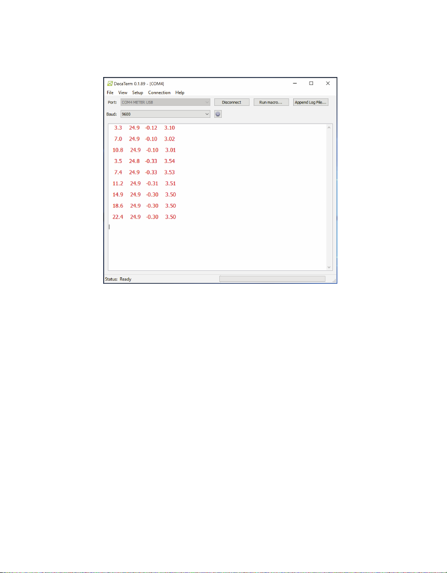
Upon successful completion of a water activity reading, the data in the terminal program
displays measurement time (in minutes), sample temperature, and water potential (in both
megapascals and picofarad). Figure16 shows a sample return.
Figure16 Sample data return
3.3 THEORY
Water potential is a measurement of the energy status of the water in a system. It
indicates how tightly water is bound, structurally or chemically, within a substance.
Water potential is defined as the potential energy per unit volume of water in a sample.
3.3.1 DEFINING WATER POTENTIAL
The total water potential of a sample is the sum of four component potentials:
gravitational, matric, osmotic, and pressure. Gravitational potential depends on the
position of the water in a gravitational field. Matric potential depends on the adsorptive
forces binding water to a matrix. Osmotic potential depends on the concentration of
dissolved substance in the water. Pressure potential depends on the hydrostatic or
pneumatic pressure on the water.
The WP4C measures the sum of the osmotic and matric potentials in a sample. Often
one or the other of these potentials will be the dominant factor in determining the total
potential. For example, solutions like the KCl calibration standard have only an osmotic
component. Soils bind water mainly through matric forces and therefore have mainly a
matric component (though salt-affected soils can have a significant osmotic component).
16
Page 21

WP4C
w
ss
WP4C computes water potential from the vapor pressure of air in equilibrium with the
sample in the sealed sample chamber. Large temperature differences between the sample
and sample block will cause longer reading times, since a complete and accurate reading
will not be made until the difference between the sample temperature and the sample
block temperature is <1.0 °C.
To monitor the temperature difference between the sample and the block, access the
Sample Temperature screen (Section3.2.4.4).
3.3.2 MEASURING WATER POTENTIAL
The water potential of a solid or liquid sample can be found by relating the sample water
potential reading to the saturation vapor pressure of air in equilibrium with the sample. The
relationship between the sample water potential (
the air is determined using Equation 1:
RT
Ψ=
M
where
• e
) is the saturation vapor pressure of the air at dew point temperature,
s(Td
) is the saturation vapor pressure at sample temperature,
• e
s(Ts
• R is the gas constant, 8.31 J/(mol × K),
• T is the Kelvin temperature of the sample, and
• M is the molecular mass of water.
Ψ) and the saturation vapor pressure of
()
eT
sd
ln
()
eT
Equation 1
In the WP4C, the sample cup is sealed against a sensor block, while a fan speeds
equilibration of the sample with the headspace vapor and controls the boundary layer
conductance of the dew point mirror. The dew point mirror measures the dew point
temperature of the air, and an infrared (IR) thermometer measures the sample temperature.
From these measurements, the WP4C computes the vapor pressure of the air in the
headspace as the saturation vapor pressure at dew point temperature. When the water
potential of the sample and the headspace air are in equilibrium, the measurement of the
headspace vapor pressure and sample temperature (from which saturation vapor pressure is
calculated) gives the water potential of the sample.
In addition to equilibrium between the liquid phase water in the sample and the vapor phase,
the internal equilibrium of the sample itself is important. If the sample is not at internal
equilibrium, one might measure a steady vapor pressure (over the period of measurement)
which is not the true water potential of the sample.
17
Page 22

SYSTEM
EC(MPa) 0.036 (ds/m)
os
3.3.2.1. TEMPERATURE EFFECTS
Temperature plays a critical role in water potential determinations. Most critical is
the measurement of the difference between sample and dew point temperature. For
water potential measurements to be accurate to 0.05 MPa, temperature difference
measurements need to be accurate to 0.006 °C.
The WP4C IR thermometer measures the difference in temperature between the sample
surface and the sample block. The thermometer is carefully calibrated to minimize
temperature errors; however, achieving 0.006 °C accuracy is difficult when temperature
differences are large. Most accurate measurements are obtained when the sample is near
block temperature.
Another effect of temperature on water potential occurs with samples that are near
saturation (like many soil samples). A sample that is close to 0.00 MPa and is only slightly
warmer than the sensor block will condense water within the block. This will cause errors
in the measurement and in subsequent measurements until the condensation disappears.
There is a linear relationship between the sample dew point temperature and its water
potential. The dew point decreases −0.12 °C/MPa. For example, a very dry sample at
−40 MPa can be 4.8 °C (−.12 × −40) above the block temperature without condensing. A
sample at −1 MPa (fairly dry for most soils) can be 0.12 °C above the block temperature
without condensing. Therefore, if the general range of the sample water potential is known,
the temperature it will condense moisture can be determined. Monitor the temperature
difference between the sample and the block using the Sample Temperature screen to
ensure the sample will not condense on the sensor block (Section3.2.4.4).
3.3.2.2. OSMOTIC EFFECTS
The WP4C measures the sum of osmotic and matric potential. An approximate value for
the osmotic potential can be found by measuring the electrical conductivity (EC) of the
saturation extract of the soil. The osmotic potential of the saturation extract is computed
using Equation 2:
Ψ=−
Equation 2
The osmotic component of the water potential is then computed using Equation 3:
θ
Ψ=Ψ
s
os
θ
Equation 3
where θ is the volumetric water content of the sample and θs is the volumetric water
content at saturation. The matric potential is the total potential minus the osmotic.
18
Page 23

WP4C
4. SERVICE
This section describes the calibration and maintenance of the WP4C. Troubleshooting
solutions and customer service information are also provided.
4.1 CALIBRATION
The WP4C uses the chilled mirror dew point technique for measuring water potential.
METER adjusts the calibration slope during factory calibration. The user can adjust the zero
offset and calibrate successfully with any solution of known water potential (S ec tion4.1.1).
Calibration can also be checked by measuring distilled water, but this is often not a good
choice. When using distilled water, the humidity of the chamber approaches 100%, which
can cause condensation to occur if the sample is warmer than the chamber. METER
recommends using the 0.5 mol/kg KCl verification standard available from METER.
The WP4C calibration should be checked before each use and at regular intervals. This will
alert the user to the possibility of contamination of the unit or shifts in the calibration from
other causes. The WP4C calibration should also be checked after cleaning to identify any
change that may have occurred during cleaning procedures.
If a change has occurred, refer to Section4.1.2 for steps to correct the calibration. If the
instrument continues to read incorrectly, contact Customer Support.
4.1.1 VERIFICATION STANDARDS
Verification standards are specially prepared salt solutions that have a specific molality
and water potential. METER recommends using potassium chloride (KCl) verification
standards. The KCl standards are accurate, easy to use, and readily available from METER,
which greatly reduces preparation errors.
The standards are produced under a strict quality assurance regime and are shelf stable for
1 year. If for some reason verification standards are not available from METER, instructions
for making a salt solution for verification are located in Appendix A.
NOTE: To avoid inaccurate water activity readings, verification standards should be used once immediately after
opening and not stored in sample cups for repeated use.
4.1.2 CALIBRATION PROCESS
Since errors in the calibration values result in errors in all values subsequently measured,
carefully follow the calibration instructions to get accurate values.
NOTE: The WP4C will automatically shift to Precise mode for calibration.
1. Check to be sure the sample temperature is below sample block temperature (lower
right button).
2. Press the lower left button to access the System Setup screen.
3. Press the upper right button to begin calibration.
19
Page 24
SERVICE
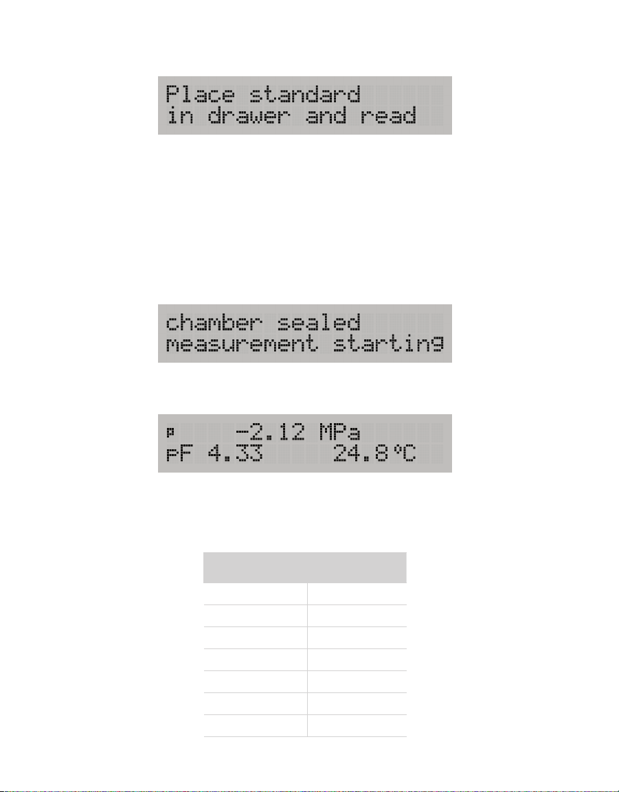
Instructions will appear (Figure17).
Figure17 Onscreen instructions
4. Empty the whole vial of KCl solution into a sample cup.
NOTE: Use the same type of sample cup (plastic or stainless steel) that will be use in subsequent
measurements.
5. Place the standard in the sample drawer and carefully slide the drawer closed to avoid
spilling solution and contaminating the chamber.
6. Turn the drawer knob to the READ position.
A notification that the measurement is starting will appear (Figure18).
Figure18 Measurement starting notification
When the reading is complete, a Results screen will appear (Figure19).
Figure19 Results screen
The reading should be within ±0.05 MPa of the correct reading of the KCl standard at
that temperature (Table 2). Results for other standards are in Appendix B.
Table 2 Water potential of 0.50 mol/kg KCl salt standard
Temperature
(°C)
15 -2.14
20 -2.18
25 -2.22
30 -2.26
35 -2.29
40 -2.33
50 -2.41
0.50 mol/kg KCL
20
Page 25

WP4C
7. If the WP4C is reading within 0.05 MPa of the standard, press –Exit– and proceed with
sample readings.
If the reading is not within 0.05 MPa of the standard, a change in calibration may have
occurred or the sensor chamber may be contaminated. Clean the chamber (Section4.3)
and repeat calibration from step1.
If, after this process, readings consistently differ from the correct water potential of the
standard by more than ±0.05 MPa, a change in calibration has probably occurred. To correct
the change, use the following steps.
1. On the Results screen, press the upper right or lower right button to move the value up
(+) or down (-), respectively.
2. When the correct value for the verification standard is reached, press the –Exit– button.
The value will be stored as a linear offset.
3. Take a normal measurement of the standard.
It should read the proper value.
If results are still incorrect, contact Customer Support.
4.2 MAINTENANCE
The WP4C may be returned to METER for maintenance in the following areas: system
inspection, parts replacement, and instrument cleaning. Replacement parts can also be
ordered from METER. Contact Customer Support for more information.
4.3 CLEANING
Cleanliness of the WP4C is vital for accurate readings. Dust and sample debris can
contaminate the sampling chamber so regular cleaning is essential The WP4C ships with a
cleaning kit that should last through about 1 year of regular cleanings. New cleaning kits
can be ordered from METER.
The KIMWIPES strips included in the cleaning kit are ideal for cleaning because they leave
very little lint residue and do not have compounds in the tissue that may contaminate
the WP4C sensors. Never use cotton swabs to clean the block sensors, as these contain
adhesives and other compounds that cause contamination.
To clean the WP4C, carefully follow the instructions in this section. The procedure to clean
the WP4C involves washing, rinsing, and drying each area.
NOTE: Wash hands with soap and water, and wear clean gloves before starting the cleaning procedure. This prevents
oils from contaminating the cleaning materials, the sample chamber, and the sensors.
NOTE: Isopropyl alcohol can be substituted for the cleaning solution.
1. Turn the WP4C power OFF.
2. Unplug the WP4C.
21
Page 26
SERVICE
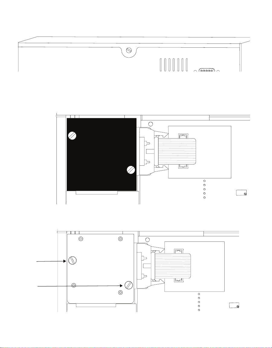
3. Remove the lid screw located on the back panel (Figure20).
Figure20 Lid screw
4. Carefully remove the lid by pulling the back of the lid upward and then sliding the lid
back (away from the front of the case) and off the unit completely.
5. Remove black foam (Figure21).
Figure21 Black foam
6. Unscrew the two thumb screws that secure the sensor block (Figure22).
Figure22 Thumb screws
22
Page 27
WP4C
Optical sensor
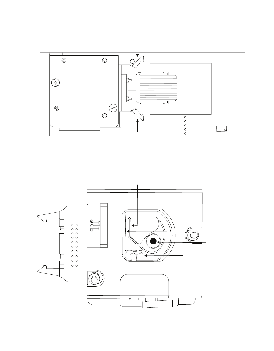
7. Pull out the two locking levers on either side of the 20-pin socket. Carefully pull out
theblue pin connector (Figure23).
Figure23 Pull out levers prior to pulling out cable
8. Carefully lift the block straight up from its mount.
9. Turn the block over to expose the chamber cavity (Figure24) and set it onto the work
area carefully.
Figure24 View of inside block
23
Mirror
IR thermometer
Fan
Page 28

SERVICE
10. Clean the sample chamber.
a. Remove any debris that may have collected within or around the sample chamber.
b. Wrap a new KIMWIPES strip around the end of the spatula and moisten it with
cleaning solution.
NOTE: Do not dip used strips into the container of IPA or cleaning solution (the IPA or cleaning solution will
become contaminated).
c. Clean all surface edges of the sample chamber including the edge where the sample
cup seals to the chamber block. Replace the strip if it becomes too dirty during this
process.
NOTE: Do not damage the fragile fan blades. If a fan blade breaks, the WP4C will not work properly.
d. Repeat stepc using new KIMWIPES strip moistened with deionized water instead of
cleaning solution.
e. Repeat stepc using new, dry KIMWIPES strip to remove any moisture remaining from
the cleaning.
f. Visually inspect the sample chamber for cleanliness. Clean again if necessary.
NOTE: Do not reuse strips.
11. Clean the mirror and optical sensor.
a. Wrap a new KIMWIPES strip around the end of the spatula and moisten it with
cleaning solution.
b. Carefully clean the mirror with the KIMWIPES strip.
c. Repeat stepb using new KIMWIPES strip moistened with deionized water instead of
cleaning solution.
d. Repeat stepb using new, dry KIMWIPES strip to help remove any moisture remaining
from the cleaning.
e. Visually inspect the mirror for cleanliness. Clean again if necessary.
12. Clean the IR thermometer.
a. Wrap a new KIMWIPES strip around the end of the spatula and moisten it with
cleaning solution.
b. Swipe the KIMWIPES across IR thermometer.
A single swipe is usually suffcient to remove contaminants.
c. Repeat stepb using new KIMWIPES moistened with deionized water instead of
cleaning solution.
d. Repeat stepb but use a new, dry KIMWIPES to help remove any moisture remaining
from the cleaning.
e. Visually inspect the IR thermometer for cleanliness. This sensor must be free of all
dirt and lint. Clean again if necessary.
24
Page 29

WP4C
13. Clean inside the case.
a. Remove any debris that may have collected within the case.
b. Wrap a new KIMWIPES strip around the end of the spatula and moisten it with
cleaning solution.
c. Clean all surface edges of the case. Replace the strip if it becomes too dirty during
this process.
d. Repeat stepc using new KIMWIPES strip moistened with deionized water instead of
cleaning solution.
e. Repeat stepc using new, dry KIMWIPES strip to remove any moisture remaining from
the cleaning.
f. Visually inspect the sample chamber for cleanliness. Clean again if necessary.
14. Ensure there is no contamination of the sample chamber cavity.
15. Replace the block, and insert the ribbon cable socket into to the 20-pin plug on the
block.
16. Lock the block into place with the locking levers.
17. Screw the thumb screws on the block back in until they are hand-tight.
18. Replace the case lid and secure the lid screw.
4.4 REPAIR
METER repairs manufacturer defects and instruments within the 1-year warranty at no
charge. Repairs outside of the warranty window are charged based on cost of parts, labor,
and shipping. An extra fee may be charged for rush work. Contact Customer Support for an
estimated repair cost.
METER has loaner instruments available for a fee while the WP4C is being serviced.
All WP4C units returning to METER for servicing must be accompanied with a Return
Merchandise Authorization (RMA) number. Prior to shipping the instrument, contact
Customer Support to obtain an RMA number.
The following steps will help to ensure the safe shipping and processing of the WP4C:
1. Ship the WP4C in its original cardboard box with suspension packaging.
If this is not possible, use a box with adequate space (at least 4 in) between the
instrument and each wall of the box.
2. Place the WP4C in a plastic bag to avoid disfiguring marks from the packaging.
3. Do not ship the power cord, serial cable, or any other accessories.
25
Page 30

SERVICE
4. If the original packaging is not available, pack the box moderately tight with packing
material (e.g., StyrofoamTM peanuts or bubble wrap), ensuring the instrument is
suspended in the packing material.
5. On the RMA form, please verify the ship to and bill to information, contact name, and
problem description. If anything is incorrect, please contact Customer Support.
6. Tape the box in both directions for added support.
7. Include the RMA number in the attention line on the shipping label.
A Certificate of Calibration will be issued upon completion of the work.
4.5 TROUBLESHOOTING
WP4C is a high-performance instrument, designed to have low maintenance and few
problems if used with care. Unfortunately, sometimes even the best operators using the
best instruments encounter technical diffculties. Table 4 lists common problems and their
solutions. If the problem is not listed or these solutions do not solve the issue, contact
Customer Support.
Table 4 Troubleshooting the WP4C
Problem Possible Solutions
Ensure power cord is securely attached to the back of the
instrument and plugged into the power outlet.
A power surge may have caused a fuse to blow. To change the fuses:
• Unplug the power cord.
• Locate the panel where the power cord plugs in. The fuse box is on
the right side of that panel.
• Press the release tab and pull the fuse-holder out.
• Pull the broken fuse out.
WP4C does not turn on
• Replace the broken fuse with a 1.25-A, 250-V fuse.
CAUTION: Do not use any other kind of fuse to avoid risk of damaging the
instrument or voiding the warranty.
• Replace the fuse holder and push it into the fuse well until the
release tab snaps in place.
• Connect the power cord and turn the instrument on.
If the fuse blows again, a failed component may be causing the
problem.
Contact Customer Support to make arrangements for repairs if the
problem persists.
26
Page 31

WP4C
Table 4 Troubleshooting the WP4C (continued)
Problem Possible Solutions
The sample chamber may be dirty. Refer to Section4.3 for
directions on cleaning the sample chamber.
Some samples absorb or desorb moisture very slowly, causing
measurements to take longer than usual, and nothing can be
Long read time
Readings on KCl standards
are too high/low to adjust
Reading message appears
< –301.8 MPa
Triangle appears in upper
right corner
Block Failure appears on
screen after turning on unit
done to speed up the process. Refer to Section2.2 for further
explanation.
The fan blade inside the block chamber may be broken. If even the
KCl standard takes a long time to read, and the sample chamber is
clean, the chamber fan blade may be broken or bent. This is likely if
the instrument chamber has just been cleaned. Contact Customer
Support for details on replacement.
The thermopile in the chamber (measures sample temperature),
may have become contaminated. Refer to Section4.3 for directions
on cleaning.
If the KCl verification standards from METER are not being used,
high readings may indicate that the salt solution being using is not
in equilibrium.
The sample is too dry for the instrument to read accurately.
If the sample has a water potential that is above the detection
limits of the instrument, this message will appear. It means that
there is not enough sample moisture to condense on the mirror and
provide a reading.
The mirror may be dirty. Cleaning the mirror and chamber and
measure the sample again (Section4.3).
This triangle is a mirror performance indicator.
Clean the mirror and the rest of the sample chamber.
When the WP4C senses that the mirror performance has dropped to
unacceptable levels, it will display the triangular warning sign after
measuring the sample. When this appears, stop sampling and clean
the chamber. If the triangle is still on the screen after cleaning, the
mirror is most likely still dirty and will need to be cleaned until the
triangle disappears.
The block is not plugged in to the motherboard.
Open the case.
Check that the small ribbon cable that connects the block to the
motherboard is snapped and locked in place.
One or more components has failed on the block circuit board.
If the block is properly plugged in to the motherboard and this
message appears, it is likely that one or more of the components
have failed on the block circuit board.
27
Page 32

SERVICE
Table 4 Troubleshooting the WP4C (continued)
Problem Possible Solutions
Set T option no longer
appears on System
Configuration menu
The temperature control module inside the WP4C is broken or not
functioning correctly. When the instrument senses that there is
a problem with the temperature control module, it removes that
function as an option as a precaution. Contact Customer Support.
4.6 CUSTOMER SUPPORT
NORTH AMERICA
Customer service representatives are available for questions, problems, or feedback
Monday through Friday, 7:00 am to 5:00 pm Pacific time.
Email: [email protected]
Phone: +1.509.332.5600
Fax: +1.509.332.5158
Website: metergroup.com
EUROPE
Customer service representatives are available for questions, problems, or feedback
Monday through Friday, 8:00 to 17:00 Central European time.
Email: [email protected]
Phone: +49 89 12 66 52 47
Fax: +49 89 12 66 52 20
Website: metergroup.de
If contacting METER by email, please include the following information:
Name
Address
Phone
NOTE: For products purchased through a distributor, please contact the distributor directly for assistance.
Email address
Instrument serial number
Description of the problem
4.7 TERMS AND CONDITIONS
By using METER instruments and documentation, you agree to abide by the METER
Group, Inc. USA Terms and Conditions. Please refer to metergroup.com/terms-conditions
fordetails.
28
Page 33

WP4C
FURTHER READING
Brye, K. R. (2003) "Long-Term Effects of Cultivation on Particle Size and Water-Retention
Characteristics Determined Using Wetting Curves." Soil Science 168 (7): 459–468.
Campbell, Eric C., Gaylon S. Campbell, and Wayne K. Barlow (1973). "A Dewpoint Hygrometer
for Water Potential Measurement." Agricultural Meteorology, 12: 113–121.
Gee, G. W., M. D. Campbell, Gaylon S. Campbell, and J. H. Campbell (1992). "Rapid
Measurement of Low Soil Water Potentials Using a Water Activity Meter." Soil Science
Society of America Journal 56(4): 1068–1070.
METER Group, Inc. "How To Create a Full Moisture Release Curve Using the
WP4C and HYPROP." https://www.metergroup.com/environment/articles/
create-full-moisture-release-curve-using-wp4c-hyprop/
Papendick, R. I. and Gaylon S. Campbell (1981). "Theory and Measurement of Water
Potential." In Water Potential Relations in Soil Microbiology, SSSA Special Publication 9,
edited by J. F. Parr, W. R. Gardiner, and L. F. Elliott, 1–22. Madison: Soil Science Society
ofAmerica.
29
Page 34

APPENDIX A
APPENDIX A. PREPARING SALT SOLUTIONS
Verification standards are specially prepared,unsaturated salt solutions with a specific
molality and water potential value that are accurately measurable. METER has verification
standards that are produced under a strict quality assurance regimen. It is also possible to
make verification standards that can read accurately if proper care is taken while preparing
the salt solutions. Tab le 5 shows the necessary concentrations to mix salt solutions to
achieve ranging water potentials. It is important to use ultrapure water when preparing
your own unsaturated salt solutions.
Tab le 5 show the water potential at given concentrations of sodium chloride (NaCl) and
potassium chloride (KCl) at 20 °C.
Table 5 Water potential of NaCl and KCl
Concentration
(mol/kg)
0.05 -0.232 -0.232
0.10 -0.454 -0.452
0.20 -0.901 -0.888
0.30 -1.349 -1.326
0.40 -1.793 -1.760
0.50 -2.242 -2.190
0.60 -2.699 -2.622
0.70 -3.159 -3.061
0.80 -3.618 -3.501
0.90 -4.087 -3.931
1.00 -4.558 -4.372
NaCl
(MPa)
KCl
(MPa)
30
Page 35

WP4C
APPENDIX B. TEMPERATURE CORRECTION OF METER
VERIFICATION STANDARDS
Table 6 provides the temperature correction for multiple verification standards available
from METER.
Table 6 Temperature correction of verification standards
Temperature
(°C)
15 0 -2.14 -10.66 -36.32 -94.32 -190.89 -261.45
20 0 -2.18 -10.99 -37.13 -94.86 -190.28 -261.24
25 0 -2.22 -11.47 -37.76 -95.37 -190.75 -261.03
30 0 -2.26 -11.67 -38.39 -95.86 -191.18 -260.83
35 0 -2.29 -11.86 -39.03 -96.32 -191.02 -260.61
40 0 -2.33 -11.89 -39.66 -96.74 -191.38 -260.39
50 0 -2.41 -16.71 -44.90 -98.38 -192.53 -262.51
Water
0.50 mol/kg
KCl
2.33 mol/kg
NaCl
6.00 mol/kg
NaCl
8.57 mol/kg
LiCl
13.41 mol/kg
LiCl
17.18 mol/kg
LiCl
31
Page 36

INDEX
INDEX
A
accuracy 6
AquaLink 15
audible notification 13
B
buttons 10
C
calibration 2, 3, 13, 26
cleaning 21–25
components
buttons 10
dew point sensor 7
display screen 8, 11–14
fan 9
LED 10
power cord 2
RS-232 cable 7
sample chamber 9–10
shipped 1
thermocouple 7, 9–10, 14
computer interface 15–16
customer support 28–29
D
DecaTerm 15
dew point temperature 17, 18
G
gravitational potential 16
I
installation 2
K
KCl standard 1, 16, 19
L
LED 10
M
maintenance 21
matric potential 16, 18
measurement 4–5
O
osmotic potential 16, 18
P
pressure potential 16
R
reading mode 14–15, 19
continuous 14, 15
fast 10, 14, 15
precise 10, 14
selecting 11
repair 25–26
S
sample cup 1, 3, 7, 20
sample preparation 3
sample storage 3
sample temperature 4, 12, 14, 17
screens
Language 11
Main 11
Model Information 11
Performance Evaluation 13–14
Sample Temperature 12–16
Temperature Set 13
settings
audible notifications 13
language 12
reading modes 14–15
temperature 13
specifications
compliance 7
measurement 6
physical 6–7
power voltage 7
read time 6–8
32
Page 37

sample cup 7
temperature 6, 7
water activity 6
T
terms and conditions 28
theory
osmotic effects 18
temperature effects 18
water potential 16–17
troubleshooting 13–14, 26–28
V
vapor pressure 17
verification standards 19, 30
W
water potential 3, 16–18
INDEX
33
Page 38

13589-01
4.30.2019
2365 NE Hopkins Court Pullman, WA 99163
E: [email protected] W: metergroup.com
E: [email protected] W: metergroup.de
© 2010, 2012−2013, 2018−2019 All Rights Reserved.
METER Group, Inc. USA
T: +1.509.332.2756 F: +1.509.332.5158
METER Group AG
Mettlacher Straße 8, 81379 München
T: +49 89 12665236 F: +49 89 1266520
Page 39

 Loading...