

Meteor Lumenator 1018 Instruction Manual

1018 - IP65 INSTRUCTION MANUAL
INTRODUCTION:
The entire staff of Meteor would like to thank you for selecting the
1018 (IP-65) LUMENATOR as your fixture of choice. We have
expended that extra effort to make sure you are more then pleased
and satisfied with your purchase.
Please check and make notice of any external cosmetic box damage
caused by transportation. Notify your dealer – he in turn will notify us.
If there is any damage – either inside the box or outside the box –
DO NOT INSTALL THE DEVICE. There is a possibility that
something may have come undone or unplugged.
Unpack the Lumenator. Inside the box – you should find:
- Protective packing
- The Lumenator
- One power cable
- One XLR cable
- Instruction manual
DESCRIPTION:
FEATURES:
- 16 BIT DIMMING
- OVER TEMPERATURE Protection
- Can set DMX Address via Controller
- 4, 6 or 9 DMX channels selectable for numerous
applications.
- Automatic Identify Master Signal and change to
Slave mode.
- Step-less RGBW COLOR mixing
- Color CALIBRATE function
- Equipped with 18 - 10w LEDS (4 in 1)
- Switch-mode power supply – 90v-240v AC.
SAFETY INSTRUCTIONS:
This lighting fixture has left our factory in perfect condition. In order to
maintain this condition and to ensure safe operation, it is absolutely
necessary for the user to follow the instructions and caution notes written in
this user manual.
This fixture falls under protection-class 1. Therefore it is essential that the
device should be grounded.
111111 MAKE SURE TO PRESS
11t11THE MIDI/ADD BUTTON AFTER
A qualified person must carry out the Electrical connection (to power). If the
external “flexible” cable or power cord of this fixture is damaged, it HAS to
be and will be replaced by the manufacturer or service agent or a similarly
qualified person in order to avoid hazard or electrical shock.
Make sure that the available voltage is NOT higher than stated at the end of
this instruction guide / manual.
Make sure the power cord is NEVER “crimped” or damaged by sharp edges.
If it is – replacing a cable must be done by an authorized dealer trained in
electrical repair.
Always disconnect from electrical MAINS, when the 1018 Lumenator is NOT
in use or before cleaning it. Definitely before cleaning it.
You could wind up getting a severe electrical shock.
Only handle power cord by the PLUG.
Never PULL out the plug by tugging on the power cord.
Very strong possibility of getting serious electrical shock.
NEVER LOOK DIRECTLY INTO THE LIGHT FIXTURE WHILE IT IS
POWERED UP – SENSITIVE PEOPLE MAY SUFFER FROM EPILECTIC
SHOCK (far fetched) BUT IT COULD HAPPEN.
IMPORTANT:
Damage caused by the disregard of this user manual IS NOT SUBJECT TO
WARRANTY. The DEALER is not and will not ACCEPT LIABILITY for any
resulting defects or problems caused by not following instructions.
IGNORANCE is NOT A VALID WARRANTY ISSUE.
*** PLEASE MAKE NOTE:
The power cord has been deliberately left OFF as most IP65 FIXTURES
ARE USED OUTSIDE and are usually hardwired into APPROVED
OUTSIDE WEATHER-PROOF JUNCTION BOXES.
Do not plug into standard unprotected outlet, except for test purposes.
2
DMX-512 Control Connection
Product has a DMX Input fitted with 3-pin XLR outdoor connectors.
Screened cables in compliance with EIA-485 specifications and the
following characteristics MUST be used for connections.
- 2 Conductors plus screen
- 120 Ohm impedance
- Low capacitance
- Max. transmission rate 250 kBaud
DMX-512 Connection with DMX Terminator
For installations where the DMX cable has to run a long distance or is
in an electrically “noisy” environment, such as a Dance Venue, it is
recommended to use a DMX Terminator. This helps in preventing
“ghosting signal” corruption of the original signal by electrical noise.
The DMX Terminator is simply an XLR plug with a 120 ohm resister
between pins 2 and 3, which is plugged into the output XLR socket of
the last fixture in the chain.
DISPLAY Menu:
Menu 1
Menu 2 (conf. Menu 1)
Axxx (address)
DMX Address Setting
SPed (Auto Speed)
Auto Speed setting (00 is fastest)
at 0 - Auto Mode 0 - fade mode
Auto Mode
at 1 - Auto Mode 1: 3 color change mode
at 2 - Auto Mode 2: 7 color change mode
Ad 0 Audio Mode 0: Fade mode
Audi (audio mode)
Ad 1 Audio Mode 1: 3 color change mode
Ad 2 Audio Mode 2: 7 color change mode
Ad 3 Audio mode 3: strobe with 7 color
CoLr (show color mode)
R for Red, G for Green, B for Blue
Hr (Power on time)
Xxxx Time in hour for Power on.
r
Red Calibrate Mode
CCAL (color Calibrate)
g
Green Calibrate Mode
b
Blue Calibrate Mode
tEp (temperature)
xxxC Temperature in C
tEp (temperature)
xxx Temperature Calibrate
Chan
CH 4: 4 Channel Mode
Chan
CH 5: 5 Channel Mode
Chan
CH 6: 6 Channel Mode
Chan
CH 9: 9 Channel Mode
3
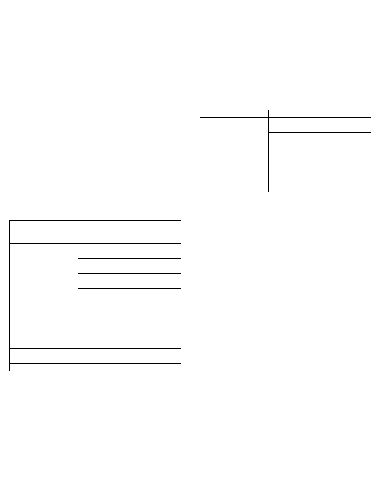
(Continued)
Chan
CH 7: 7 Channel Mode
diCS
Inst: Instant Mode: Light on / off instant
DELA: Delay Mode: Light on / light off delay
for 5 Seconds
CnFg (parameter config)
Loc Active self lock keyboard - no operation
LoCc
on the button for 30 seconds
Unloc: Deactivate self lock keyboard if NO
operation on the button for 30 seconds
StAt
HoLd: Hold DMX status when no DMX signal
oFF: Light OFF when no DMX signal
MAIN FUNCTIONS:
Axxx: Current DMX Address
A – Setting DMX Address using Buttons
1 – Press Enter Button when the display shows Axxx
Menu, then adjust the DMX address by pressing {UP}
or {DOWN} to get to desired Base address channel
number.
PRESS {ENTER} to confirm or {ESC} return to Menu
B – Setting DMX address by Controller
1 – Set the DMX Value of Channel 5 to 10-15, Channel 6 to
20-26, Channel 7 to 30-36, Channel 8 to 40-46. Then
the fixtures connected to the controller will enter the
address setting mode.
2 - Set the DMX value of Channel 1 from 0-59, then you will
see the first number of the address change ( Channel
1
value) 10. For example: when you set the value of
channel 1 to 20, the first DMX address number will be
2 (20/10=2)
3 – Set the DMX value of Channel 2 from 0-99, then you will
see the first number of the address change (Channel 2
value)/10.
For example: when you set the value of channel 2 to
30, the first DMX address number will be 2(30/10=3)
4 - Set the DMX value of Channel 3 from 0-99, then you will
see the first number of the address change (Channel 3
value) 10.
For example: when you set the value of channel 1 to
40, the first DMX address number will be 3(40/10=4)
5 - Set the DMX value of Channel 4 from 255, then you will
4
 Loading...