

Page 1
C-80
DMX LIGHTING CONTROLLER
______________
5
577
8
8
9
0
0 1 2 3 4 5 6 7 8 9
1/8
2/8
DMX LIGHTING CONTROLLER
C-80
channels
1
23344
1
2
Active Fixtur es / Page Sel ection
scene
Program
Program
Scene
Enter
Chase
Operators Manual
MLSC Inc.
MLSC Inc.
MLSC Inc.MLSC Inc.
8000 Madison Pike, Madison, Alabama 35758
Tel (256) 461–8000 Fax: (256) 461–7708
Website: meteor-global.com e-mail: sales@meteor-usa.com
C----80 DMX CONTROLLER
80 DMX CONTROLLER
C
C
80 DMX CONTROLLER80 DMX CONTROLLER
C
Please read t
operate / program controller. Once you feel you understand the
instructions, locate the instructions in a place where you will
remember where they are for future reference and additional help in
using your controller
hese instructions carefully before attempting to
CONTENTS:
1.
35 Chases – each up to 48 Scenes
2
1 -
2 -
3 -
4 -
INTRODUCTION / FEATURES
The C-80 DMX CONTROLLER is a standard DMX 512
Controller capable of controlling up to 80 DMX channels
simultaneously. Simplicity to operate and use, and had to
maintain high quality programmability was the mission
statement.
The main features include:
10 Fixtures up to 8 channels each
100
8 Faders to adjust DMX output level from 0 – 255.
Extremely Easy Operation and Programming
Mix and Match any DMX Lighting fixture
Power On / Off switch on back of Controller
SPECIFICATIONS:
Po
DMX OUTPUT: 3 Pin or 5 pin Female XLR connector
Size: 12” L x 6.5” w x 2.5” h (not rack mountable)
Weight: 7lbs
Power supply: included
NTRODUCTION / FEATURES
I
FUNCTIONS
OPERATING INSTRUCTIONS
TROUBLE SHOOTING
Scenes capable
wer Input: DC9 – 12v 300mA
Page 2
C-80
DMX LIGHTING CONTROLLER
______________
5
57788
9
0
0 1 2 3 4 5 6 7 8 9
3/8
4/8
channels
1
2
scen e
Progra m
Progra m
Chas e
Scen e
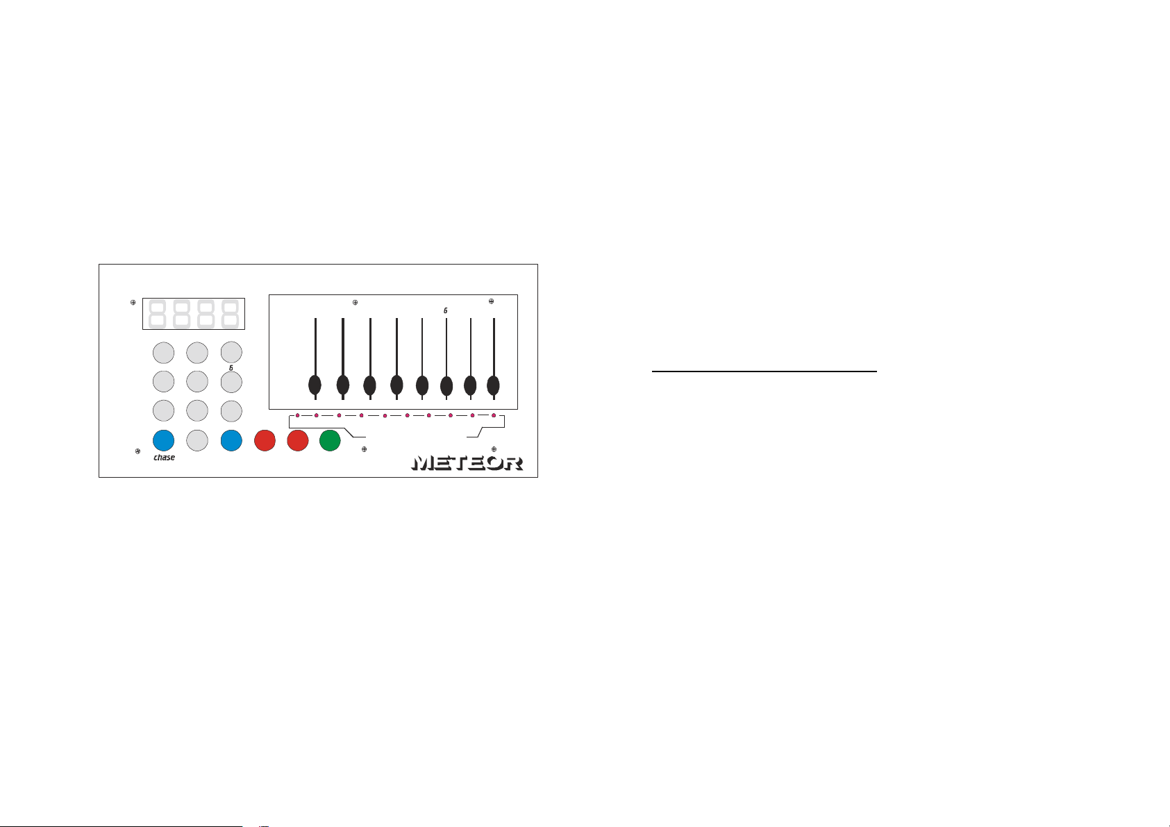
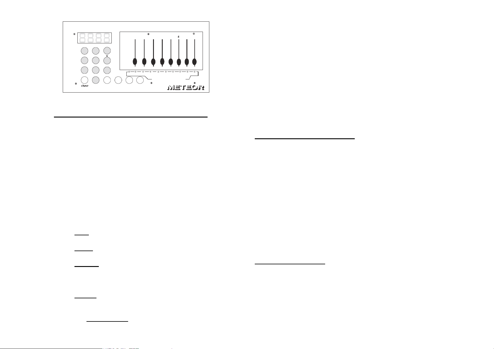
2 TERMINOLGY and FEATURE / FUNCTIONS:
SCENES The “look”. To create - store or run position
of recorded fixture settings, held in memory
ACTIVE FIXTURE / PAGE SELECTION: Indicates which
“fixture” you are using. These SLIDERS will
display a true DMX Level value. Labeled 0 – 9.
(1 – 10). The red LED’s above the numbers (0 - 9)
on the bottom will be lit when “on or active”
showing which fixture(s) you have current control
of.
LCD Display: 4 digit “Readout” showing Numeric value
of DMX channel / Level or Scene or Chase
4 Different COLORED COMMAND Buttons - 2 Red,
2 Blue, 1 Green and 10 Gray.
indicates either “
RED
“Program a Scene”.
BLUE
specific CHASE.
GREEN is used when wanting to ENTER a change
or Finish a command. Press Green when you
finish a programming a SCENE or programming a
CHASE.
GRAY: (0 – 9) Indicates the actual Fixture / Object
you will have control of. Red LED light will also
come on in Active Display you
CHASES (Blue Button):
is to either Select a Specific SCENE or a
23344
1
Active Fixtures / Page Selection
Ente r
Program a Chase”
To select any 1 of 35
or
Programmed. LCD Screen will change / display
Chase desired by numerically pressing any of the
Gray buttons.
Ex: Chase 2- press Grey Button 0 and Gray Button
2. Press Enter.(Green button)
SCENES: LCD window will Display which Scene is
available for edit / programming
FADERS / SLIDERS ( 1 – 8 ): to adjust and vary the
output level either from 0 – 255 or the intensity
from 0% - 100% of each channel.
FIXTURE: Each fixture is capable of running up 8
channels of DMX. Base addresses are set
accordingly
START – UP PROCEDURES:
2 - Connect either 3 Pin or 5 pin XLR cable to DMX
3 - Turn switch to on position on the back of
4 - Controller goes through a DMX check. Red LED’s
5 - Controller is now ready to start Programming.
CREATING A SCENE:
1 - Plug Power Supply into back of controller
output on rear of unit. Make sure all fixtures have
DMX cable connected correctly
controller.
scan backwards to “0”. LCD Flashes C-80. LCD
changes to read “000”.
Note: If any of the 8 sliders are in the “up” position, the LCD
will display the level of the slider closest to the LCD at time of
turning controller on. Make sure ALL slider are down.
The C-80 Controller allows you to create and Program up
to 100 Scenes (0 – 99). A SCENE is a particular look
/position. Whether it be the color, or a particular gobo or a
mirror position. Once you have that look – that is a
SCENE. All DMX values are then stored in memory bank.
Controller has the LCD at 000. And the red LED is
Page 3

on slider 0. You are ready to create a SCENE 01
5/8
6/8
1 - Press the Red button “Program Scene. The
LCD window changes to SC _ _ : (flashing)
2 - Press the Grey Button 0 (LCD window
changes to SC 0 __ ).
3 - Press the Grey Button 1 (LCD window
changes to SC 0 1 ).
4 - Press the GREEN Button – Enter. Hold for
2 seconds. LCD window changes to 0 0 0.
5 - The red LED is already on “0”. Depending
on how many channels you have in your
fixture, You can now more the any of the
18 - When finished PROGRAMMING Scene 2.
corresponding channel sliders up to desired
levels or mirror positions colors or gobos.
(note): The C-80 Controller uses “later takes
precedent”. Meaning if you bring slider 1 (channel 1)
up to 50% and then move Slider 2 (channel 2) up to
25%. The slider you are changing is what will be
displayed in the LCD window.
19 - Do as many Scenes as you want, up to 100.
CHANGING / EDITING A SCENE.
1 - Press “Blue” Scene button. Enter the
2 - Press ENTER (Green) Button. The lights
6 - Fixture 1 is set where you want it.
7 - Press Grey Button 1 (actually fixture 2
now). Both red LED’s (0 and 1) are on.
3 - If the lights, color and position are correctly
Press Grey button 0 and the disables the
red LED on the first fixture. Leaving the
4 - If deciding that you want to “edit or change
second red LED on.
8 - Move the corresponding sliders to the color,
gobo, mirror position you want it to be in.
5 - Press the Fixture you want to start with. The
Fixture 2 is now is the position you want it to
be.
9 - Press Grey button 3. The red LED is now lit
on the second and third fixture. Press Grey
6 - Adjust the light(s) to where you want them.
7 - Press ENTER (Green) and hold. That
button 2 and that disables fixture to leaving
10 -
you to position fixture
Position fixture 3 in the place you want it to
be.
3.
11 - Press fixture 4 (gray button 3).The red LED
comes on. Press fixture 3 (gray button 2)
and the red LED goes out.
12 - Position that fixture where you want it to be.
13 - If you need to go back and edit any part of
this “SCENE” Now is the time to do it. Just
press the corresponding fixture and change
the level / positions
14 - Satisfied – Press the GREEN button
(ENTER). That is now your SCENE 0
1
15 - To go on and create your next scene(s).
16 - Press Program Scene. LCD changes to
SC__ __ . Press gray Button 0 and gray
Button 2. Press enter.
Repeat all steps 4 – 14.
17 -
Press Green Button (ENTER)
Scene you want to edit / change. ie:(SC01)
and position assigned to that scene will go
to where you had it programmed.
placed. Just press enter.
that Scene. Press Program Scene. Retype
in the Scene you are changing. Ex: (SC01)
Red LED will show you what fixture(s) you
have control of.
Scene has now been overwritten. New
Scene values have been stored.
Page 4

7/8
8/8
MAKE SURE ALL FIXTURES WERE RECORDED IN SCENE
MAKE SURE YOU ARE IN THE CORRECT BANK THAT THE
SCENES WERE RECORDED IN
CHASES DON’T RUN AFTER RECORDING THEM
SCENES DON’T RUN AFTER RECORDING THEM
MAKE SURE TO PRESS MIDI / ADD BUTTON BEFORE
PRESSING SCENE BUTTON. LED’s SHOULD FLASH
AFTER PRESSING EACH SCENE BUTTON.
BE SURE YOU ARE IN THE CORRECT BANK THAT THE
SCENES WERE RECORDED IN.
SCENES DON’T RUN CORRECTLY AS RECORDED
MAKE SURE TO PRESS THE MIDI/ADD BUTTON AFTER
PRESSING THE SCENE BUTTON. LED SHOULD FLASH
AFTER PRESSING MIDI / ADD.
BE SURE YOU ARE IN THE CORRECT CHASE THAT HAS
THE STEPS RECORDED IN
IF IN AUTO MODE – DID YOU ADJUST SPEED AFTER
SELECTING AUTO
FADE TIME IS TOO LONG FOR SPEED SELECTED
FIXTURES AREN’T DOING ANYTHING
HAVE YOU READ THIS MANUAL COMPLETELY AND
FOLLOWED ALL THE RECORDING STEPS FOR
SCENES AND CHASES
DID YOU SET YOUR DIP SWITCHES ACCORDING TO THIS
MANUAL
ARE ALL UNITS PROPERLY CONNECTED WITH POWER
ON AND PROPERLY CONNECTED VIA DMX.
FOR TECHNICAL HELP / SUPPORT
MLSC Inc.
MLSC Inc.
MLSC Inc.MLSC Inc.
8000 Madison Pike, Madison, Alabama 35758
Tel (256) 461–8000 Fax: (256) 461–7708
Website: meteor-global.com e-mail: sales@meteor-usa.com
 Loading...