

Page 1

Fun Imager
(model 8310)
User Manual
v1.01
Page 2

NOTICE:
This device complies with Part 15 of the FCC
Rules. Operation shall be subject to the following
two conditions:
(1) This device may not cause harmful interface,
and
(2) This device must accept any interface received,
including interface that may cause undesirable
operation.
This equipment has been tested and complied with
the limits for a Class a digital device, pursuant to
Part 15 of the FCC Rules. These limits are
designed to provide a reasonable protection
against harmful interface when the equipment is
operated under a commercial environment. This
equipment generates, uses, and can radiate radio
frequency energy and, if not installed and used in
accordance with the instruction manual, may
cause harmful interface to radio communications.
Operation of this equipment in a residential area is
likely to cause harmful interface in which case the
user will be required to correct the interface at his
own expenses.
Note
: All brands and trademarks shall belong to their
respective owner.
Page 3

Note
: Specification is subject to changes without
notice.
Using the Scanner
8110/8150/8250/8310/8312
The Scanner can automatically scan barcode at a
distance. Simply aim and pull the trigger. Code scanning
is performed along the center of the light bar emitted
from the reading window. This bar must cover the entire
code.
Successful scanning shall be obtained by tilting the
scanner with respect to the barcode to avoid direct
reflections that impair the reading performance,
especially for 2D barcode.
Recommended Steps
When the required settings have been configured, all
settings are stored in non- volatile memory of scanner
after reading EXIT Label. Recommended steps are as
follows.
1) Set right host interface for your scanner.
(The scanner is in factory default shown as bold
label)
2) Set interface to optimize protocol of scanner with
your host in interface section.
3) Set system control of scanner, such as specific
adjustments double confirm, power saving, indicator
and scanning mode which you prefer usage in
system control section.
4) Set code options of scanner for your usage in code
option section. You must make sure to enable the
symbology first, then Min./Max. code length, code
Page 4

ID checksum and truncate digits are also converted.
5) Set string format of the scanner, such as preamble,
postamble Prefix, suffix, code ID and code name
transmission for your application in string format
section.
Note:
If still not work properly. Please contact your dealer
for further information.
CONTENTS
Chapter 1 Introduction
Introduction…………………………..………………. 1
Default Setting ………………………………………. 2
Scanner8110 specification ………..…………….. 4
Scanner8150/8250/8310/8312 specification 7
Programming the Scanner….…………………….. 10
Chapter 2 Parameter Setting
Interface……………………………………………….… 12
Interface Selection ………………………………….. 12
Keyboard wedge ……………………………………. 13
RS-232 …………………………………………….…. 18
Wand Emulation …………………………….………. 21
Pin Assignments ……………………………………. 24
System Control………………………………………. 26
Scan …………………………………………………. 26
Indication …………………………..………………… 30
Code Option…………………………………….……… 32
UPCA ……………………………………..…………. 32
UPCE ………………………………………………… 36
EAN-13 ………………………………………………. 40
EAN-8 ………………………………………………… 44
Code 39 ……………………………………………… 48
Interleaved 2 of 5 …………………………………… 52
Page 5

Industrial 2 of 5 ……………………………………… 54
Matrix 2 of 5 Eur …………………………………… 56
Codabar ……………………………………………… 58
Code-128 …………………………………………… 61
Code-93 ……………………………………………… 65
Code-11 ………………………………………….…… 68
MSI/Plessey …………………………………………. 70
UK/Plessey ………………………………………….. 72
Telepen ………………………………………………. 74
Standard 2 of 5 ……………………………………… 76
RSS-14 ………………………………………………. 78
RSS-Limited…………………………………..…… 80
RSS-Expanded…………………………………..….. 82
China Post …………………………………………… 84
Italian pharmacode ………………………………… 86
Code 16K …………………………………..………… 88
PDF-417 ……………………………………………… 89
Micro-PDF…………………………………..……….. 91
EAN UCC Composite……………………………….. 93
String Format…………………………………………… 95
String Setting ………………………………………… 95
Transmission ………………………………………… 98
Appendix………………………………………………… 102
Test Chart ……………………………………………. 102
ASCII Code Table …………………………………… 105
Parameter setting List ………………………………. 106
Page 6

0
Page 7

Introduction
Installation- Keyboard Wedge
1) First of all, you must switch off power for the
terminal/computer.
2) Disconnect the keyboard cable from the back of the
terminal/computer.
3) Connect the appropriate interface cable to the
scanner and to the terminal/computer.
4) Turn the terminal/computer power on.
RS-232
1) Disconnect power to the terminal/computer.
2) Connect the appropriate interface cable and external
power supply (DC adapter) to the scanner.
3) Plug the serial connector into the serial por t on the
back of your computer/terminal. Tighten the two
screws to secure the connector to the port.
4) Plug the power pack into power source.
5) Once the scanner has been fully connected, turn the
terminal/computer power back on.
USB (Simulate with keyboard wedge)
1) Connect the USB cable between scanner and PC.
2) Windows will automatically detect the USB device.
Note:
If any of the above operation is incorrect, turn off the
power immediately and checking any improper
connections. Go through all above steps again.
1
Page 8

Default setting
For each barcode shown as below:
Read
Code Type
UPC-A V V V A
UPC-E V V V E
EAN-13 V V V F
EAN-8 V V V FF
Code-39 V *
Interleaved
2 of 5
Industrial
2 of 5
Matrix 2 of 5 B
Codabar V %
Code-128 V V #
Code-93 V two digits &
Code-11 V One digit O
MSI/Plessey V @
UK/Plessey V @
Te le pe n S
Standard 2 of
5
RSS-14 - R4
RSS-Limited - RL
RSS-Expande
d
China Post t
Italian
Pharmacode.
Code-16K -
PDF417 -
Micro-PDF - U
EAN UCC
Composite
Enable
8110
Checksum
Verification
Enable
V i
- - i
- - i
- RX
p
- RC
2
Checksum
Transmission
Enable
Code
ID
Page 9

Read
Code Type
UPC-A V V V V A
UPC-E V V V V E
EAN-13 V V V V F
EAN-8 V V V V FF
Code-39 V V *
Interleaved
2 of 5
Industrial
2 of 5
Matrix 2 of 5 B
Codabar %
Code-128 V V V #
Code-93 V two digits &
Code-11 V One digit O
MSI/Plessey V @
UK/Plessey V @
Te le pe n S
Standard 2 of 5 V V i
RSS-14 - R4
RSS-Limited - RL
RSS-Expanded - RX
China Post t
Italian
Pharmacode.
Code-16K - - -
PDF417 - V - -
Micro-PDF - V8312 - - U
Enable
8150
8310
V V i
- - i
p
8250
8312
Checksum
Verificatio
n
Enable
Checksum
Transmission
Enable
Code
ID
3
Page 10

EAN UCC
Composite
- - - RC
4
Page 11
Scanner 8110
Specification Model 8110
Operational
Light Source 660 nm Visible Red LED
Optical System 2048 pixel CCD
(Charge-coupled device)
Depth of Scan
Field
Scanning Width 80 mm
Scan Speed 50 scans/sec
Resolution 0.127mm(5mils) Code39,PCS=45%,
Print Contrast 30% or more
Scanning Angle Pitch: 60° Skew: 75°
Decode Capability Autodiscriminates all standard
Beeper Operation 7 tones or no beep
Indicator Green led
Mechanical
Length 182 mm
Width-handle 26 mm
Width-head 90 mm
Depth-handle 51 mm
Depth-head 35 mm
Weight 155 g (cable not included)
(CODE 39, PCS=90%, 20mils)
barcodes; Other symbologies can be
0-80 mm
on contact
ordered optionally
5
Page 12
Cable – K/B wedge
Cable – universal
type
Connector type RJ-45 phone jack connector
Case material ABS+PC
Cushion material Rubber
Electrical
Input Voltage 5 VDC ± 0.25V
Power - Operating 380 mW
Power - Standby 240 mW
Current -
Operating
Current - Standby 48 mA @ 5 VDC
DC Transformers Class 2; 5VDC @ 450 mA
Agency listing UL, FCC Class A,CE
Environmental
Operating
Temperature
Storage -40℃ to 60℃
Humidity 5% to 90% relative humidity,
Light Level Up to 15000 Lux
Shock 1.0m drop onto concrete
Contaminants Seals to resist airborne par ticulate
Ventilation None required
Straight 2.0 m
Straight 2.3 m
76 mA @ 5 VDC
0℃ to 45℃ (32℉ to 113℉)
(-40℉ to 140℉)
non-condensing
contaminants
6
Page 13

Programming
Programming
method
Program upgrade Enabled by built-in flash memory
Programmable
characteristics
Manual (Reading special barcode)
DOS command through RS-232,
Windows configuration program
Code type selection, check digit
selection Decoding option Decoding
option Transmitted character delay,
Header selection, trailer selection,
message suffix, good read beep
tone and volume, scanner trigger
selection
Keyboard emulation type
(intermessage delay, keyboard type
and keyboard language)
Serial interface type (ACK/NAK,
Xon/Xoff, RTS/CTS, good read LED
control, start/stop bits)
7
Page 14
Scanner 8150 / 8250 / 8310 / 8312
Specification Model
8150/8250
Operational
Light Source 660 nm Visible
Red LED
Optical System 2048 pixel CCD
(Charge-coupled device)
Depth of Scan
Field
Scanning Width 120 mm 160mm
Scan Speed 200 scans/sec 450 scans/sec
Resolution 0.1mm(4mils)
Print Contrast 30% or more 25% or more
Scanning Angle Front: 60° Rear: 60° Yaw: 75°
Decode Capability Autodiscriminates all standard
Beeper Operation 7 tones or no beep
Indicator Green led Green & Red led
Mechanical
Length 182 mm 164 mm
Width-handle 26 mm 30 mm
Width-head 74 mm 78 mm
Depth-handle 51 mm 56 mm
0-250 mm
(CODE 39,
PCS=90%,
20mils)
Code39,PCS=90%
barcodes; Other symbologies can be
ordered optionally (2D symbologies
for 8250 and 8312 only)
8
Model
8310/8312
630 nm Visible
Red LED
Up to 600mm
(CODE 39,
PSC=90%,
20mils)
0.1mm(4mils)
Code39,PCS=90%
Page 15
Depth-head 35 mm 35 mm
Weight 160 g (cable not
included)
Cable – K/B wedge Straight 2.0 m Coiled 2.5 m
Cable – universal
type
Cable- USB Straight 2.0 m Coiled 2.5 m
Connector type RJ-45 phone jack connector
Case material
Cushion material Rubber Double injection
Electrical
Input Voltage 5 VDC ± 0.25V
Power - Operating 1275 mW 800 mW
Power - Standby 600 mW 350 mW
Current -
Operating
Current - Standby 120 mA @ 5 VDC 70 mA @ 5 VDC
DC Transformers Class 2; 5VDC @ 450 mA
Agency listing UL, FCC Class A,
Environmental
Operating
Temperature
Storage -40℃ to 60℃
Humidity 5% to 90% relative humidity,
Straight 2.3 m Coiled 2.5 m
PC
255 mA @ 5 VDC 160 mA @ 5 VDC
CE
0℃ to 45℃
(32℉ to 113℉)
(-40℉ to 140℉)
non-condensing
176 g (cable not
included)
ABS (over molded
at contact
pointed)
UL, FCC Class B,
CE
0℃ to 50℃
(32℉ to 122℉)
-20℃ to 70℃
(-4℉ to 158℉)
9
Page 16

Light Level Up to 60000 Lux Up to 70000 Lux
Shock 1.5m drop onto concrete
Contaminants Seals to resist airborne par ticulate
contaminants
Ventilation None required
Programming
Programming
method
Program upgrade Enabled by built-in flash memory
Programmable
characteristics
Manual (Reading special barcode)
DOS command through RS-232,
Windows configuration program
Code type selection, check digit
selection Decoding option Decoding
option Transmitted character delay,
Header selection, trailer selection,
message suffix, good read beep
tone and volume, scanner trigger
selection
Keyboard emulation type
(intermessage delay, keyboard type
and keyboard language)
Serial interface type (ACK/NAK,
Xon/Xoff, RTS/CTS, good read LED
control, start/stop bits)
10
Page 17

Programming the Scanner
8110/8150/8250/8310/8312
To program the 8110/8150/8250/8310/8312, you must
scan a series of programming barcode in the correct
order. Fold out the back cover of this manual. You will see
a table of alphanumeric barcodes, which are used to
program the various options presented.
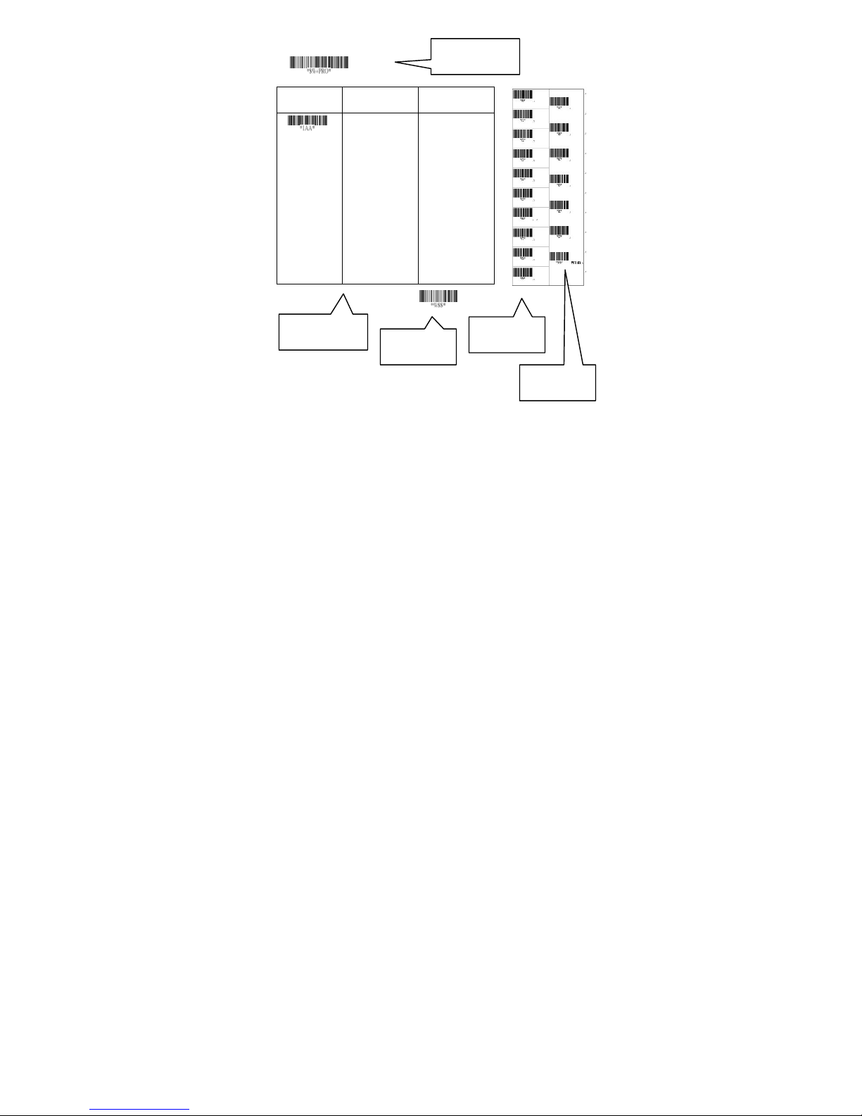
To program each option, you must:
1. Scan the Program barcode on the parameter setting
part.
2. Enter the option mode by scanning the Option Bar
Code (also on the Parameter setting part).
3. To the right of the option barcode, the necessary
alphanumeric inputs are listed. Scan these
alphanumeric entries from the back fold out page. To
confirm above steps, you must scan the Finish
barcode on the back fold out page.
4. Once you have finished programming. Scan the Exit
barcode, listed on the lower right hand corner of each
parameter setting part.
11
Page 18
Option Bar Code Option Alphanumeric Entry
Program
Program Barcode
Interface
selection
Option Barcode
Keyboa rd Wedge
RS-232
Wand emulation
USB
Keyboard/RS-232
Auto detection
Rese rved
Exit Barcode
00*
01
02
03
04
05
Exit
Back Fold Out
Finish barcode
12
Page 19
Interface Selection
This decoder built-in scanner comes in one model and
supports interfaces such as keyboard wedge, RS232
serial wedge, wand emulation, and the latest USB
interface. In most of the cases, simply selecting an
appropriate cable with a device code will work for a
specific interface.
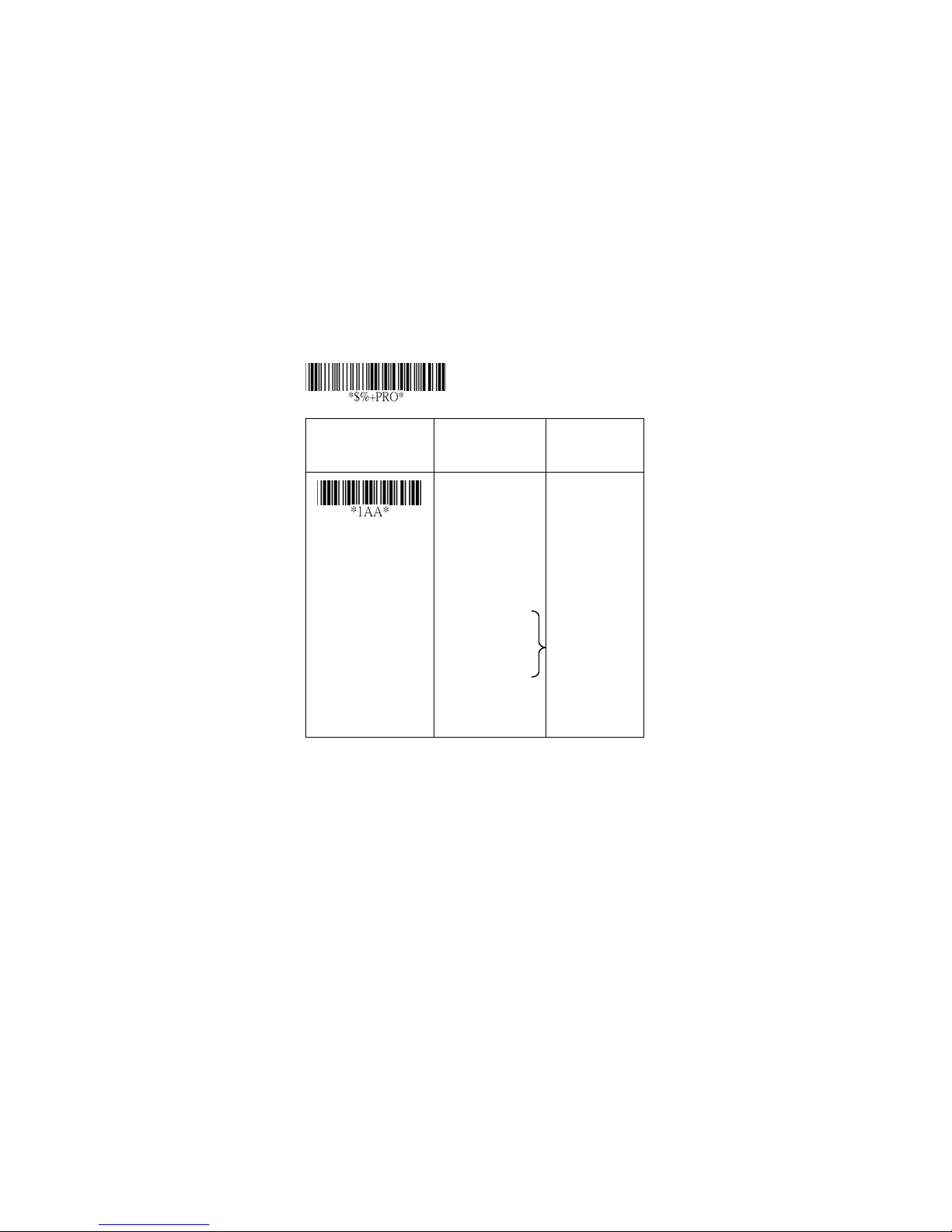
Interface selection: You can change factory interface
default for other type interface. By plugging different
cables, setting right interface, then the scanner will be
changed to another interface. However, you must make
sure which cable you need.
Keyboard/RS232/UBS Auto detection: By setting this
function, it will automatically select the Keyboard wedge
or RS-232 or UBS interface for user.
Option Bar Code Option Alphanumeric
Program
Entry
Interface selection
Note:*-Default
Keyboard Wedge
RS-232
Wand emulation
USB
Keyboard
/RS232/USB
Auto detection
Reserved
13
00
01
02
(8110/8150/8250
)
03
04
*
05
Page 20

Exit
14
Page 21
Keyboard wedge
As a keyboard interface, the scanner supports most of
the popular PCs and IBM terminals. The installation of
the wedge is a fairly simple process without any changes
of software or hardware.
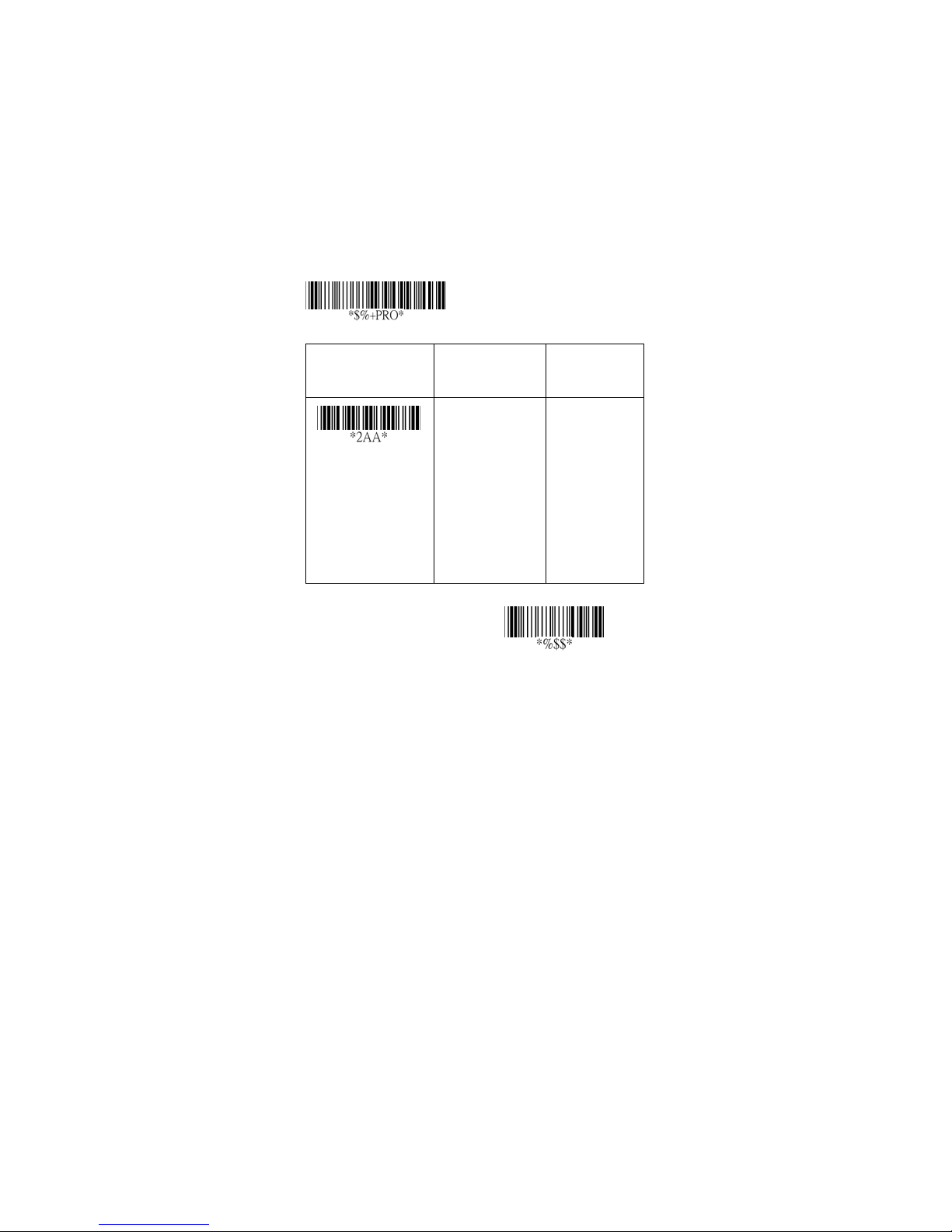
Keyboard Type: Select keyboard type connector of your
host computer. Scanner must be selected to the
appropriate host interface cable converter.
Option Bar Code Option Alphanumeric
Program
Entry
Keyboard type
IBM AT, PS/2
Reserved
Reserved
Reserved
Reserved
Reserved
Reserved
15
00
01
02
03
04
05
06
*
Exit
Page 22
Keyboard wedge
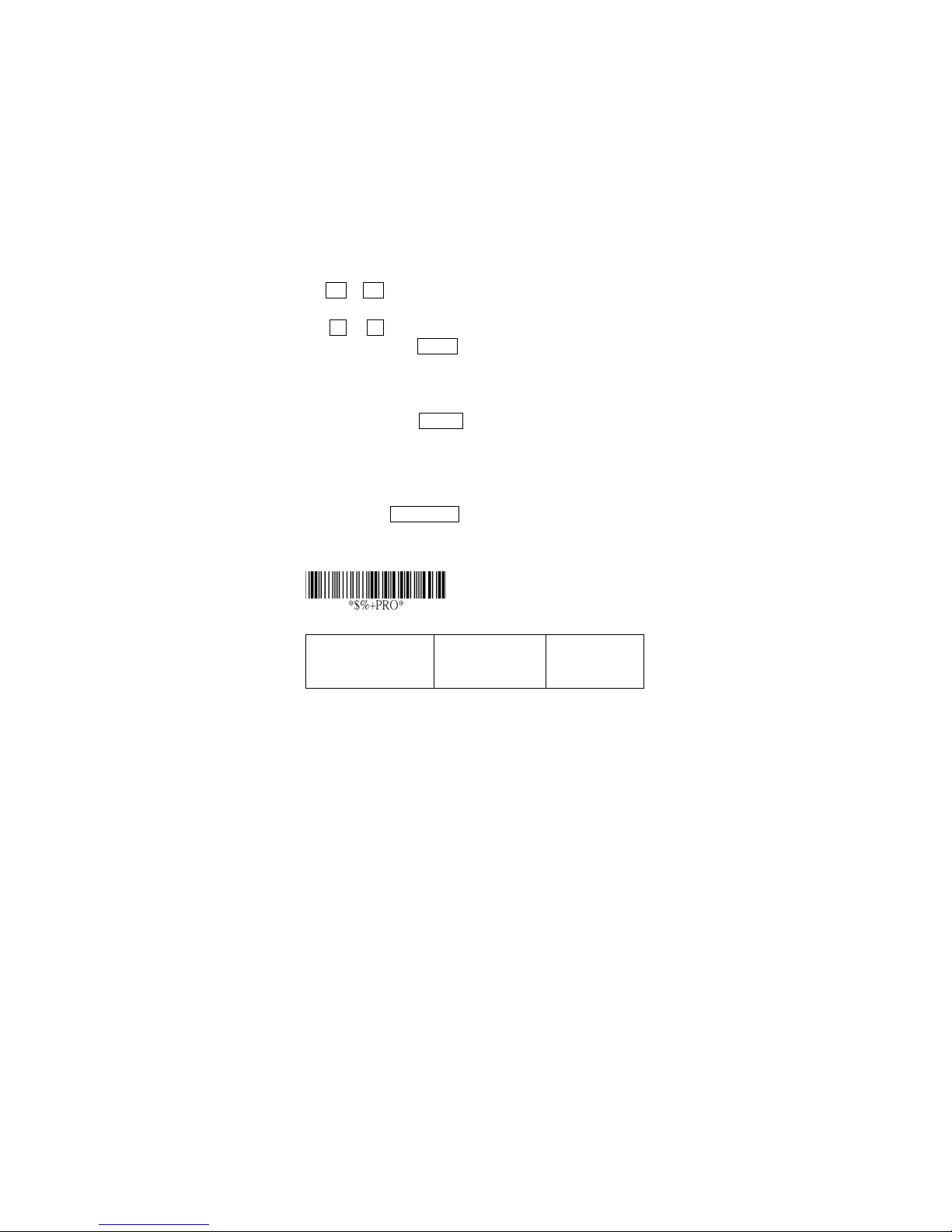
Keyboard Layout: The selecting of keyboard layout
supports many country languages other than USA
keyboard layout. First you need to confirm country
language that you desire. In DOS, using command “keyb”
to select the desirable keyboard layout or in WINDOWS
entry “Control” then pops “Keyboard” to select country at
“language” item. For details, please refer to your DOS or
WINDOWS user’s manual.
Keyboard Speed: By selecting, you can change output
speed of scanner to match with host computer. Generally,
set 00 or 01 in working high speed. If some output
characters of barcode have been lost, you may need to
set 05 or 06 to match your host keyboard speed.
Function Key: Set Enable, scanner can output code as
pressing function-key in your application program while
the barcode datas contain ASCII value between 01
16. Refer to ASCII table.
1F
Numeric Key: The Keypad has to be selected if your
application program is only keypad numeric code
acceptable. So, scanner will output code as press
numeric keypad when it read numeric digit. (The keypad
is in the right side of keyboard, and Num Lock control key
is also on.) If Alt+Keypad is selected, Caps Lock and
output will be independent.
Program
Option Bar Code Option Alphanumeric
16 to
Entry
16
Page 23
Keyboard layout
USA
Belgium
Danish
Fra nce
Germany
00
01
02
03
04
*
Keyboard speed
Function key
Numeric key
Italian
Portuguese
Spanish
Swedish
Switzerland
UK
Latin American
Japanese
0-8
0 : high clock
rate
8 : low clock rate
Disable
Enable
Alphabetic key
Numeric keypad
(Num lock state
05
06
07
08
09
10
11
12
00-08
01
*
03 *(8310/8312)
00
01
*
00
*
01
only)
Alt+Keypad
17
02
Exit
Page 24

Keyboard wedge
Caps Lock: By selecting Caps lock”ON” or Caps
lock”OFF”, scanner can get Caps Lock status.
Power-on simulation: All of the PCs check the keyboard
status during power-on selftest. It is recommended to
Enable function if you are working without keyboard
installation. It simulates keyboard timing and pass
keyboard present status to the PC during power-on.
Inter-character delay: This delay is inserted after each
data characters transmitted. If the transmission speed is
too high, the system may not be able to receive all
characters. Adjust it and try out suited delay to make
system work properly.
Block transmission delay: It is a delay timer between
barcode data output. The feature is used to transfer
continually with shorter barcode data or multi-field
scanning.
18
Page 25
Program
Option Bar Code Option Alphanumeric
Entry
Caps lock
Pow er-on
simulation
Inter-character
delay
Block transmission
delay
Caps lock”ON”
Caps lock”OFF”
Disable
Enable
00-99 msec 00-99
00-99 10 msec 00-99
00
01
00
01
02
10
*
*
*
*
Exit
19
Page 26

RS-232
CTS: Clear To Send (Hardware Signal)
RTS: Request To Send (Hardware Signal)
Xon: Transmit On (ASCII Code 11
Xoff: Transmit Off (ASCII Code13
Flow control:
None-The communication only uses TxD and RxD signals
without regard for any hardware or software handshaking
protocol.
RTS/CTS-If the scanner wants to send the barcode data
to host computer, it w ill issue the RTS signal first, wait for
the CTS signal from the host computer, and then perform
the normal data communication. If there is no replied
CTS signal from the host computer after the timeout
(Response Delay) duration, the scanner will issue a 5
warning beeps.
Xon/Xoff- When the host computer is unable to accept
data, it sends a Xoff code to inform the scanner to
suspend data transmission, and Xon to continue.
ACK/NAK- When the ACK/NAK protocol is used, the
scanner waits for an ACK (acknowledge) or (not
acknowledge) from the host computer after data
transmission, and will resend in response to a NAK.
Inter-character delay: It is delay time between data
character’s data output. It is also same as Inter-char.
delay of keyboard wedge.
Block transmission delay: It is a delay time between
barcode data output. It is also same as Block
transmission delay of keyboard wedge.
Response delay: This delay is used for serial
communication of the scanner to waiting for
16)
16)
20
Page 27
handshaking acknowledgment from the host computer.
Program
Option Bar Code Option Alphanumeric
Entry
Flow control
Inter-character
delay
Block transmission
delay
Response delay
None
RTS/CTS
Xon/Xoff
ACK/NAK
00-99 (msec)
00-99 (10 msec)
00-99 (100
msec)
00
01
02
03
00-99
00
00-99
00
00-99
20
*
*
*
*
Exit
21
Page 28
Program
Option Bar Code Option Alphanumeric
Entry
Baud rate
Parity
Data bit
Stop bit
300 BPS
600 BPS
1200 BPS
2400 BPS
4800 BPS
9600 BPS
19200 BPS
38400 BPS
None
Odd
Even
8 bits
7 bits
One bit
Two bit s
00
01
02
03
04
05
06
07
00
01
02
00
01
00
01
*
*
*
*
Exit
22
Page 29
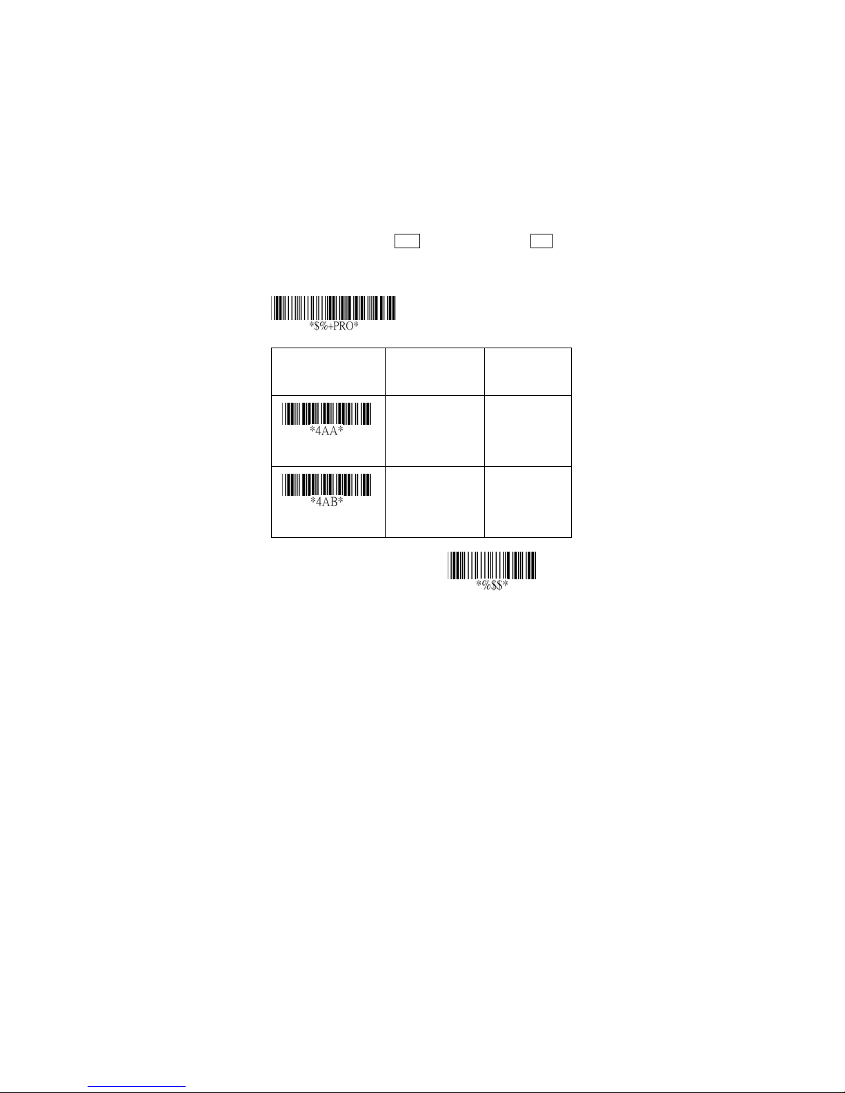
Wand Emulation ( 8310/8312
except )
Bar/space polarity:
High/low- Black will be transmitted as a high voltage
level (+5) and space as low level (0V).
Low/high- Black will be transmitted as a low voltage level
(0V) and space as high level (+5).
Initial polarity: You must make sure what is Initial
polarity of your wand decode device in stand-by (idle). So,
initial signal state as a High voltage level (+5) or Low
voltage level (0V).
Option Bar Code Option Alphanumeric
Program
Entry
Bar/space polarity
Initial polarity
High/low
Low/high
Low
High
23
00
01
00
01
*
*
Exit
Page 30

Wand Emulation ( 8310/8312
except )
Output speed: This setting is same as serial
transmission baud rate, and it must be approbated your
wand decode resolution. The unit of speed is a width of
minimum narrow bar.
Margin delay: It is a timer of zone like space zone of
barcode label margin. The width of margin time will be
added before and after in each barcode data
automatically when it is transmitted.
Transmit delay: It is a delay time between barcode data
output. It is the same as Block transmission delay of
keyboard wedge.
24
Page 31
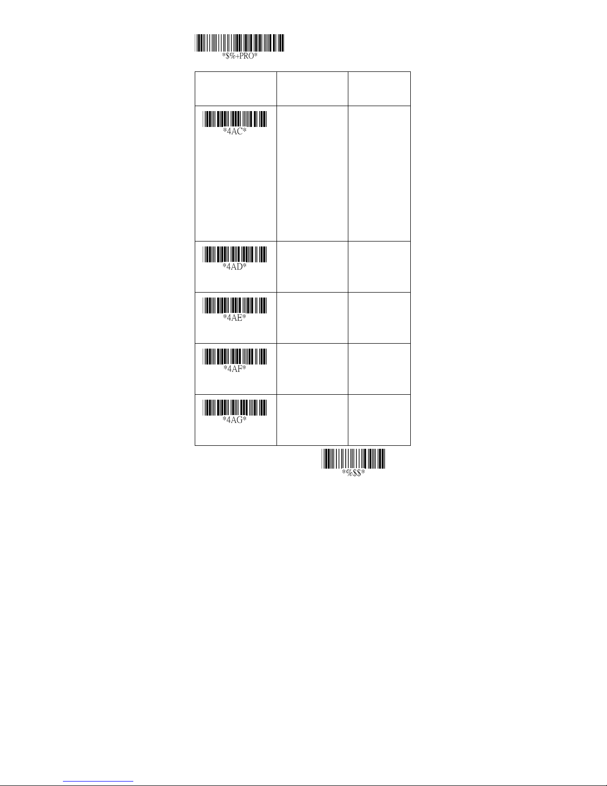
Program
Option Bar Code Option Alphanumeric
Entry
Output speed
Reserved
Reserved
Margin delay
620 pps
1250 pps
2500 pps
5000 pps
10000 pps
20000 pps
*pps: pixel per
second
00-99 (10 pixel)
00
01
02
03
*
04
05
00
*
00
*
00-99
*
15
Tra ns mi t d el ay
00-99 (10 msec)
25
00-99
30
*
Exit
Page 32
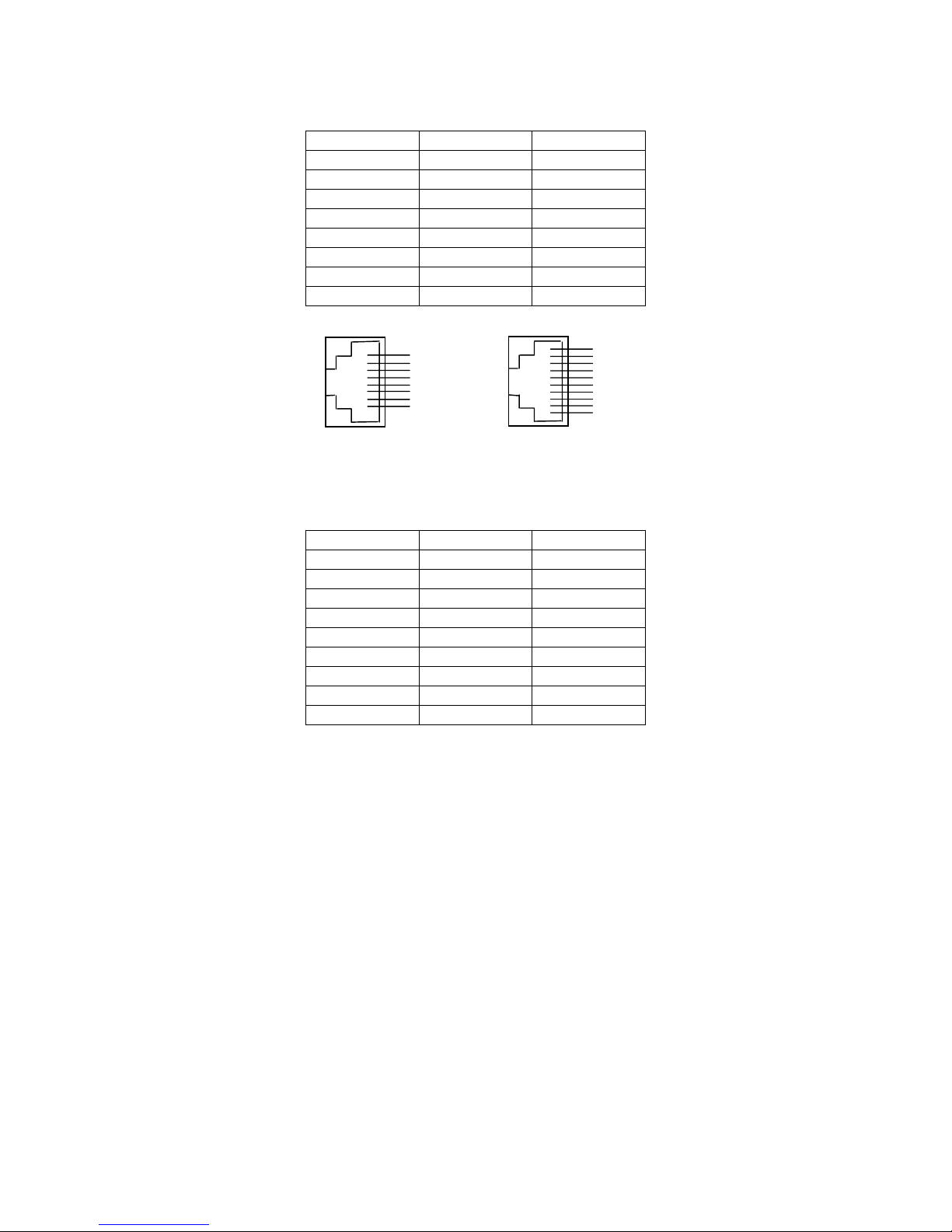
Pin Assignments
AS Series RJ-45 Connector (AS-8110, 8150, 8250)
Pin RS-232 Keyboard
1 VCC (+5V) VCC (+5V)
2 TXD NA
3 NA CLK / PC
4 NA DATA / PC
5 CTS DATA / KB
6 RXD NA
7 RTS CLK / KB
8 GND GND
8-pin (8110, 8150, 8250) 10-pin (8310,
8312)
AS Series RJ-45 Connector (AS-8310, 8312)
Pin RS-232 Keyboard
1 I/F I/F
2 VCC (+5V) VCC (+5V)
3 TXD NA
4 NA CLK / PC
5 NA DATA / PC
6 CTS DATA / KB
7 RXD NA
8 RTS CLK / KB
9 GND GND
1
2
3
4
5
6
7
8
1
2
3
4
5
6
7
8
9
10
26
Page 33
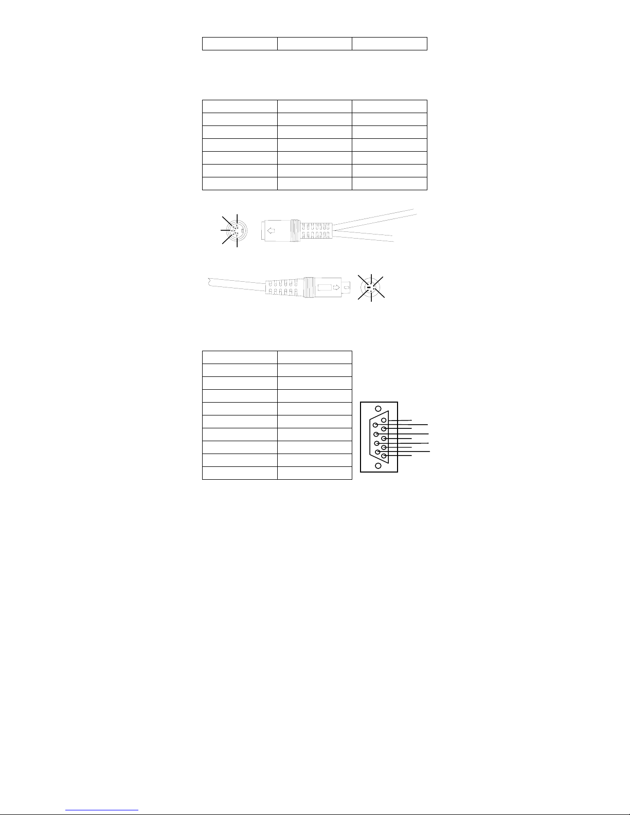
10 GND GND
Keyboard Wedge Combo Connector (To Host Side):
Pin Mini-DIN 6P Male
1 DATA / PC CLK / KB
2 NC GND
3 GND DATA / KB
4 VCC (+5V) VCC (+5V)
5 CLK / PC NC
6 NC NA
4
3
2
Mini-DIN 6P Male Connector
RS-232 DB-9F Connector (To Host Side):
Pin Definition
DIN 5P Female Connector
5
1
1 NC
2 TXD
3 RXD
4 NC
5 GND
6 NC
7 CTS
8 RTS
9 VCC (+5V)
DIN 5P Female
4
6
2
5
1
3
5
9
4
8
3
7
2
6
1
27
Page 34

Scan
Scanning mode:
Good-read off-The trigger button must be pressed to
activate scanning. The light source of scanner stops
scanning when there is a successful reading or no code is
decoded after the Stand-by duration elapsed.
Momentary-The trigger button acts as a switch. Press
button to activate scanning and release button to stop
scanning.
Alternate-The trigger button acts as a toggle switch.
Press button to activate or stop scanning.
Timeout off-The trigger button must be pressed to
activate scanning, and scanner stops scanning when no
code is decoded after the Stand-by duration elapsed.
Continue-The scanner always keeps reading, and it does
not matter when trigger button is pressed or duration is
elapsed.
Double read timeout: If the barcode has been scanned
twice, then only the first barcode will be accepted.
Double confirm: If it is enabled, the scanner will require
a several times successful decoding to confirm the
barcode data. The more confirming times required the
more inhibitive miss-reading code will be shown. If you
set Double confirm, the Multi field scan Enable function
won’t be able to work.
Global min./max. code length: Global Minimum and
Maximum length can be set to qualify data entry. The
length is defined as the actual barcode data length to be
sent. Label with length exceeds these limits will be
rejected. Make sure that the Minimum length setting is no
greater than the Maximum length setting, or otherwise
the labels of the symbology will not be readable. In
particular, you can set the same value for both Minimum
and Maximum reading length to force the fixed length
barcode decoded. The values of setting have no effect on
28
Page 35
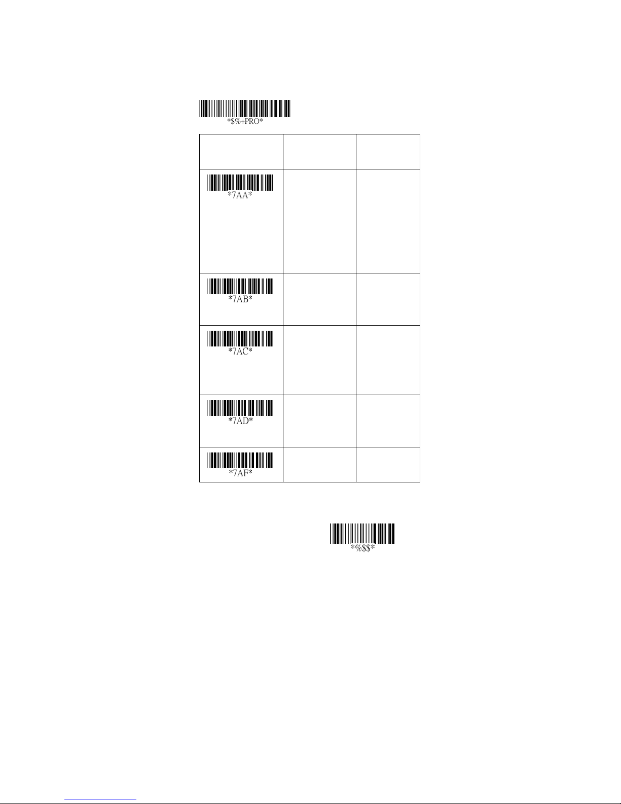
certain symbologies with fixed length.
Notes 1): Please set the min/max length if you have
special demand for individual barcode.
2): Include the Check sum digits if you want to set
Global min/max code length.
Program
Option Bar Code Option Alphanumeric
Entry
Scanning mode
Stand-by duration
Double read
timeout
Double confirm
Good-read off
Momentary
Alternate
Timeout off
Continue
Test o nly
01-99 (second) 00-99
01-99 (10 msec)
00-99
(00: no double
confirm)
00-63 00-63
00
01
*
02
03
04
05
06
*
01-99
50
*
00-09
00
*
29
04*
Page 36
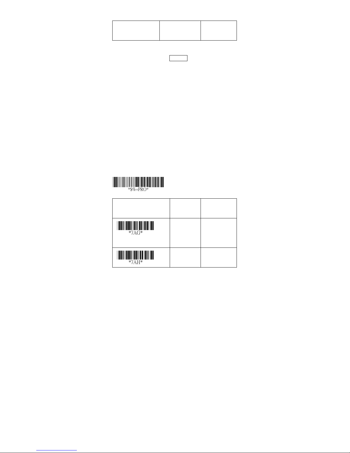
Global min. code
length
Scan
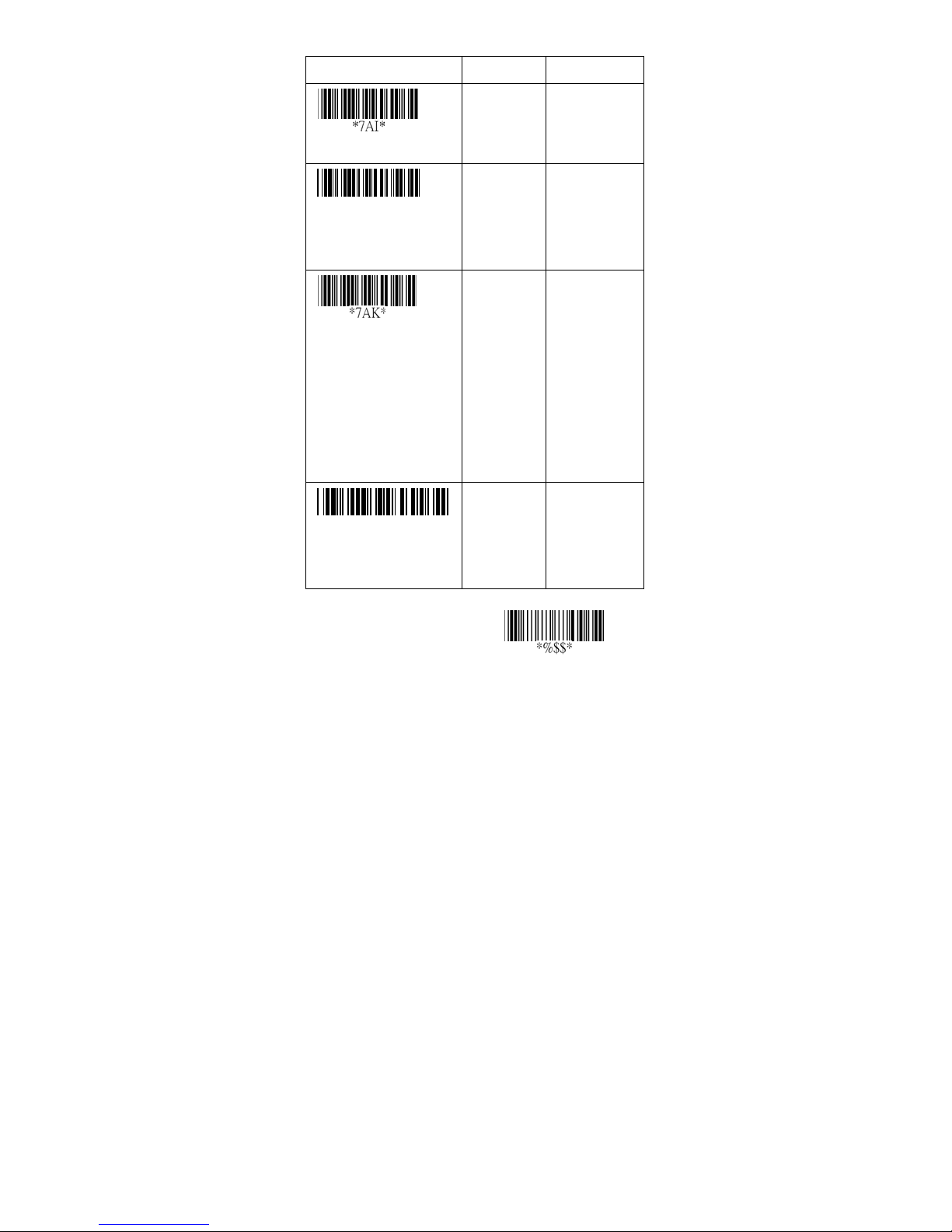
Inverted image scan: Set Enabled the scanner will scan
both black/white barcode with white/black background.
CTS trigger: This operation enabled an external device to
control scanning. The CTS trigger is controlled by apply
an external trigger signal to the CTS input. When active,
this signal causes scanning to begin as the scanner’s
trigger was depressed.
Power saving: Place the scanner in a idle state during
idle priced to optimize power usage.
Position indication(8110except): This function can
indicate the specific location before scanning. You can
also set up the time of indication.
Option Bar Code Option Alphanumeric
Program
Global max.code length
Entry
00-63 04-63
63
*
Disable
Enable
00
01
*
30
Page 37
Inverted image scan
CTS trigger
*7AJ*
Pow er saving
(For 8310/8312)
Pos ition indicat ion
*7AL*
Stand mode selection
Disable
Enable
Disable
Enable
Disable
30 second
60 second
90 second
120 second
150 second
180 second
Continue
LED ‘’on’’
LED ‘’off’’
00
01
00
01
00
01
02
03
04
05
06
07
00
*
01
*
*
*
(For 8310/8312)
Exit
31
Page 38

Indication
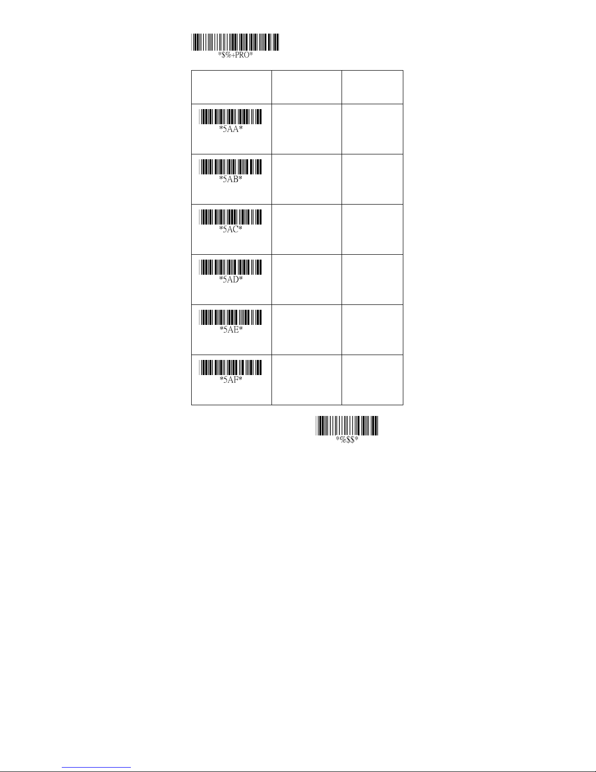
Power on alert: After power-on the scanner it will
generate an alert signal to indicate a successful self-test.
LED indication: After each successful reading, the LED
above the scanner will light up to indicate a good barcode
reading.
Beeper indication: After each successful reading, the
scanner will beep buzzer to indicate a good barcode
reading, and its Beep loudness, Beep tone freq. and
Beep tone duration are adjustable.
Beep loudness/Beep tone freq./Beep tone duration:
You can adjust Beep Loudness, Beep tone and Beep
duration for a good reading upon favorite usage.
Exit
32
Page 39
Program
Option Bar Code Option Alphanumeric
Entry
Disable
Enable
Pow er on a lert
Disable
Enable
LED indication
Disable
Enable
Beeper indication
00-07 00-07
Beep loudness
00-99 (100Hz) 00-99
Beep tone freq.
00-99 (10 msec)
Beep tone duration
00
01*
00
01
00
01*
07*
26
00-99
10
*
*
*
Exit
33
Page 40
UPCA
Read: For ma t
Leading
Zero
Check-sum transmission: By setting Enable, checks sum
will be transmitted.
Truncate leading/ending: The leading or ending digits of
barcode data characters can be truncated when these
values are set to non-zero. It will beep instead of reading
anything when the truncate value is more than the
barcode data digits or the value of Truncate Leading is
overlapped with that of the Ending. The maximum value
of truncate digits is 15.
Code ID setting: Code ID setting is a character used to
represent the symbol upon a succeeding reading. A Code
ID setting is prefixed to the data begin or end transmitted
if the feature is selected. If you want application to
transmit Code ID, you must set Code ID transmission to
Enable first. Refer to Code ID transmission.
Insertion group selection: The scanner offer one or two
insertion group for own symbology. By setting one or two
digits to indicate which insertion group you want to insert.
You may refer to Character insertion.
Example: Group 2 → set 02 or 20.
Group 1 and 4 → set 14 or 41.
Program
Option Bar Code Option Alphanumeric
Data Digits
(11 Digits)
Check
Digit
Entry
Disable
Enable
34
00
01*
Page 41
Read
Check-sum verification
Check-sum
transmission
Truncate leading
Tru ncate ending
Code ID setting
Disable
Enable
Disable
Enable
0-15 00-15
0-15 00-15
00-ffH
ASCII code
00-44 00-44
00
01*
00
01*
00*
00*
00-ffH
< A >
*
Insert group selection
00*
Exit
35
Page 42
UPCA
Supplement digits: The Supplement digits barcode is the
supplemental 2 or 5 characters for WPC code.
Form at
Supplement Digits
Leading
Truncation / Expansion: The leading “0” digits of UPCA
data characters can be truncated when the function is
enabled.
Zero
Data Digits
(11 Digits)
Option Bar Code Option Alphanumeric
Check
Digit
Program
2 or 5 or
UCC / EAN 128
Entry
Supplement digits
(For
8110/8150/8250)
None
2 digits
5 digits
UCC/EAN 128
Auto detection
36
00
01
02
03
04
*
Page 43
Supplement digits
(For 8310/8312)
None
2 digits
5 digits
2,5 digits
UCC/EAN 128
00*
01
02
03
04
Truncation/
Expansion
(For 8110)
Truncation/
Expansion (For
8150/8250/8310/
8312)
The
2, UCC/EAN
128
5, UCC/EAN
128
All
Disable
Enable
None
Truncate leading
zero
Expand to
EAN13
05
06
07
00
01
00
01
02
*
*
Exit
37
Page 44
UPCE
Read: For ma t
Leading
Zero
Check-sum verification: The checksum of EAN-13 is
optional and made as the sum of the numerical value of
the data digits.
Check-sum transmission: By setting Enable, checks sum
will be transmitted.
Truncate leading/ending: Refer to Truncate
leading/ending of UPCA.
Code Id setting: Refer to Code ID setting of UPCA.
Option Bar Code Option Alphanumeric
Data Digits (6
Program
Digits)
Check
Digits
Entry
Read
Check-sum
verification
Disable
Enable
Disable
Enable
38
00
01*
00
01*
Page 45
Check-sum
transmission
Disable
Enable
0-15 00-15
00
01*
Truncate leading
Tru ncate ending
Code ID setting
0-15 00-15
00-ffH ASCII
code
00*
00*
00-ffH
< E >
*
Exit
39
Page 46
UPCE
Insertion group selection: Refer to Insertion group
selection of UPCA.
Supplement digits:
Form at
Leading
Zero
Expansion: The expansion function is used only for UPCE
and EAN-8 code reading. It extends to 13-digits with “0”
digits when the feature is enabled.
Example: Barcode “0123654”
Output: “0012360000057”
UPCE-1: To enable scanner to read UPCE with leading
digit 1.
Data
Digits
(6 Digits)
Program
Option Bar Code Option Alphanumeri
Supplement Digits
Check
Digit
2 or 5 or
UCC/EAN 128
c Entry
Insert group selection
Supplement digits
(For
8110/8150/8250)
00-44 00-44
None
2 digits
5 digits
UCC/EAN 128
Auto detection
00
*
00
*
01
02
03
04
40
Page 47
Supplement digits
(For 8310/8312)
None
2 digits
5 digits
2,5 digits
UCC/EAN 128
00
*
01
02
03
04
Truncation/Expansio
n
(For 8110)
Truncation/Expansio
n
(For
8150/8250/8310/
8312)
2, UCC/EAN
128
5, UCC/EAN
128
All
Disable
Enable
None
Truncate leading
zero
Expand to
EAN13
Expand to UPCA
05
06
07
00
*
01
00
*
01
02
03
Expansion
Disable
Enable
00
*
01
41
Page 48

*OAM*
UPCE-1
Disable
Enable
00
*
01
Exit
42
Page 49
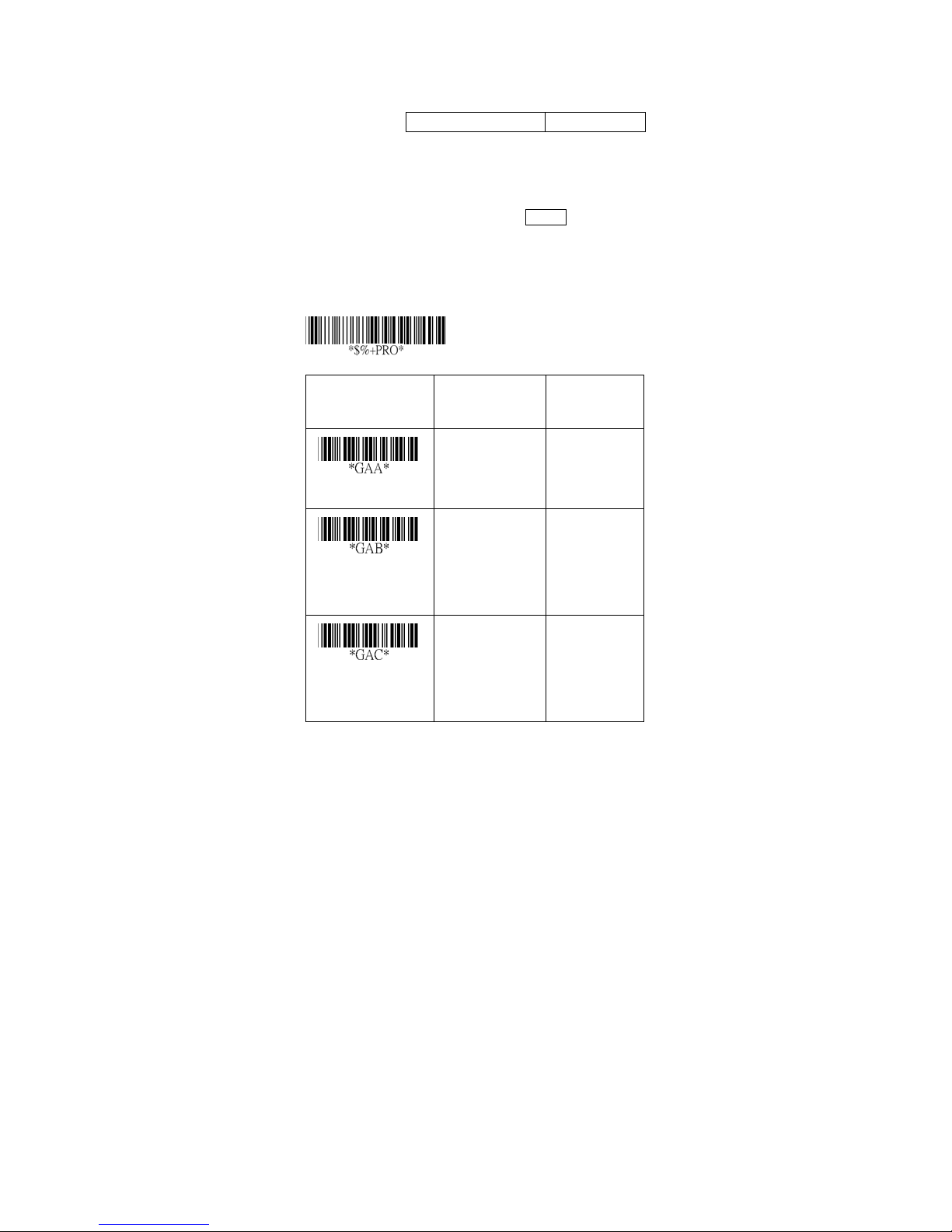
EAN-13
Read: For ma t
Data Digits (12 Digits) Check Digits
Check-sum verification: The checksum of EAN-13 is
optional and made as the sum of the numerical value of
the data digits.
Check-sum transmission: By setting Enable, checks sum
will be transmitted.
Truncate leading/ending: Refer to Truncate
leading/ending of UPCA.
The
Option Bar Code Option Alphanumeric
Program
Entry
Read
Check-sum
verification
Check-sum
transmission
Disable
Enable
Disable
Enable
Disable
Enable
43
00
01*
00
01*
00
01
*
Page 50

0-15 00-15
Truncate leading
0-15 00-15
Tru ncate ending
00*
00
*
Exit
44
Page 51
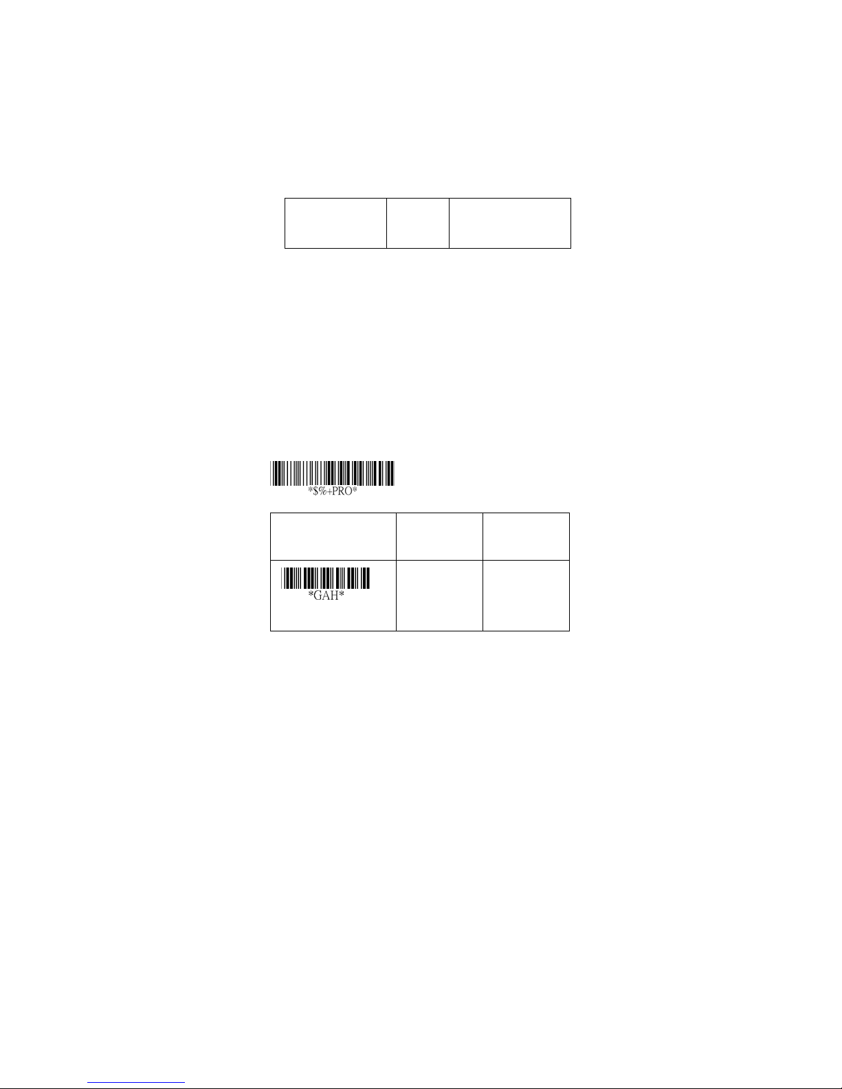
EAN-13
Code Id setting: Refer to Code ID setting of UPCA.
Insertion group selection: Refer to Insertion group
selection of UPCA.
Supplement digits:
Form at
Data Digits
(12 Digits)
ISBN/ISSN: The ISBN (International Standard Book
Number) and ISSN (International Standard Serial
Number) are two kinds of barcode for book and
magazines. The ISBN is 10 digits with leading “978” and
the ISSN is 8 digits with leading “977” of the “EAN-13”
symbology.
Example: Barcode “9789572222720” - Output:
“9572222724”
Example: Barcode “9771019248004” - Output:
“10192484”
Check
Digits
Supplement Digits
2 or 5 or
UCC / EAN 128
Program
Option Bar Code Option Alphanumeric
Entry
Code ID setting
00-ffH ASCII
code
45
00-ffH
< F >*
Page 52
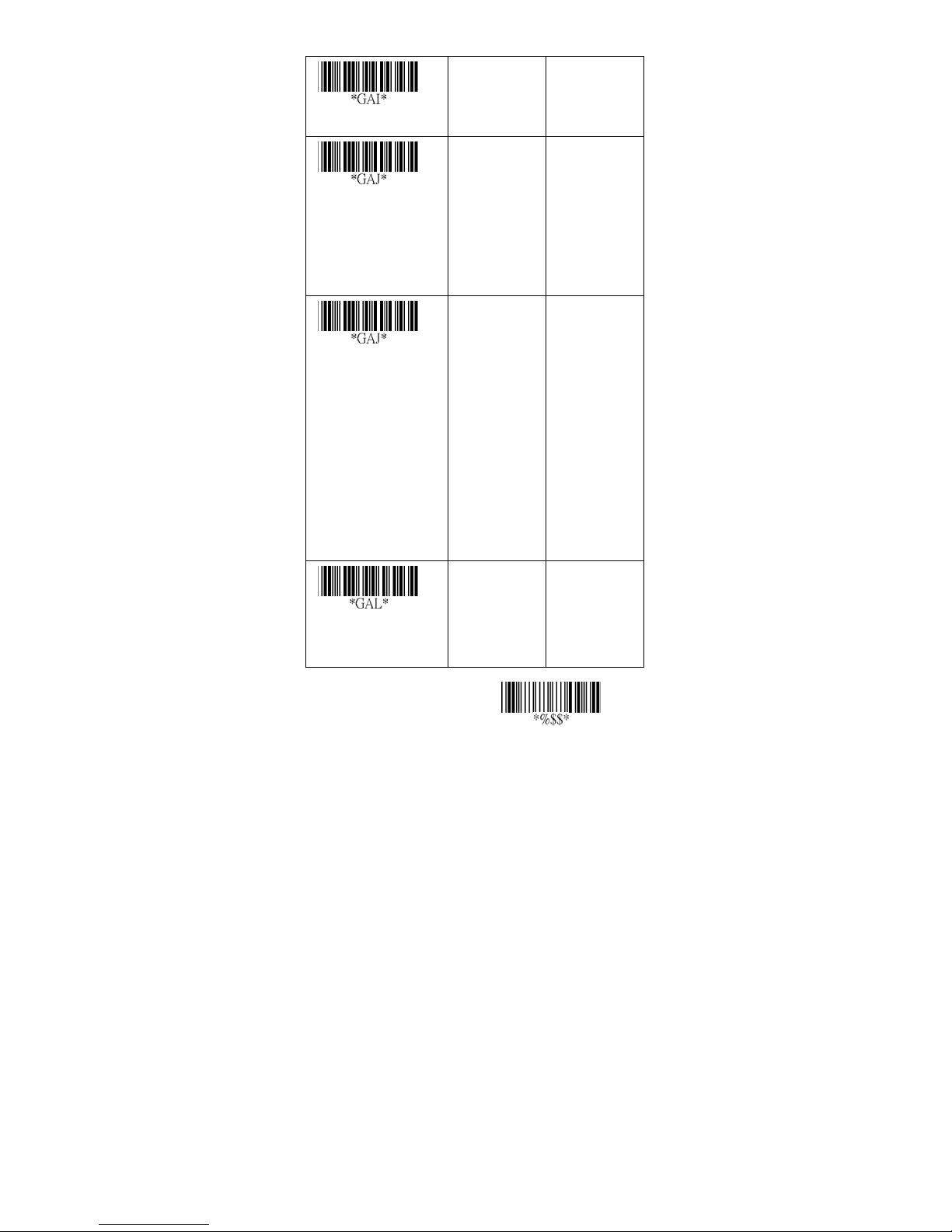
Insert group selection
00-44 00-44
00
*
Supplement digits
(For
8110/8150/8250)
Supplement digits
(For 8310/8312)
ISBN/ISSN
conversion
None
2 digits
5 digits
UCC/EAN 128
Auto
detection
None
2 digits
5 digits
2,5 digits
UCC/EAN 128
2, UCC/EAN
128
5, UCC/EAN
128
All
Disable
Enable
00
01
02
03
04
00
01
02
03
04
05
06
07
00
01
*
*
*
Exit
46
Page 53
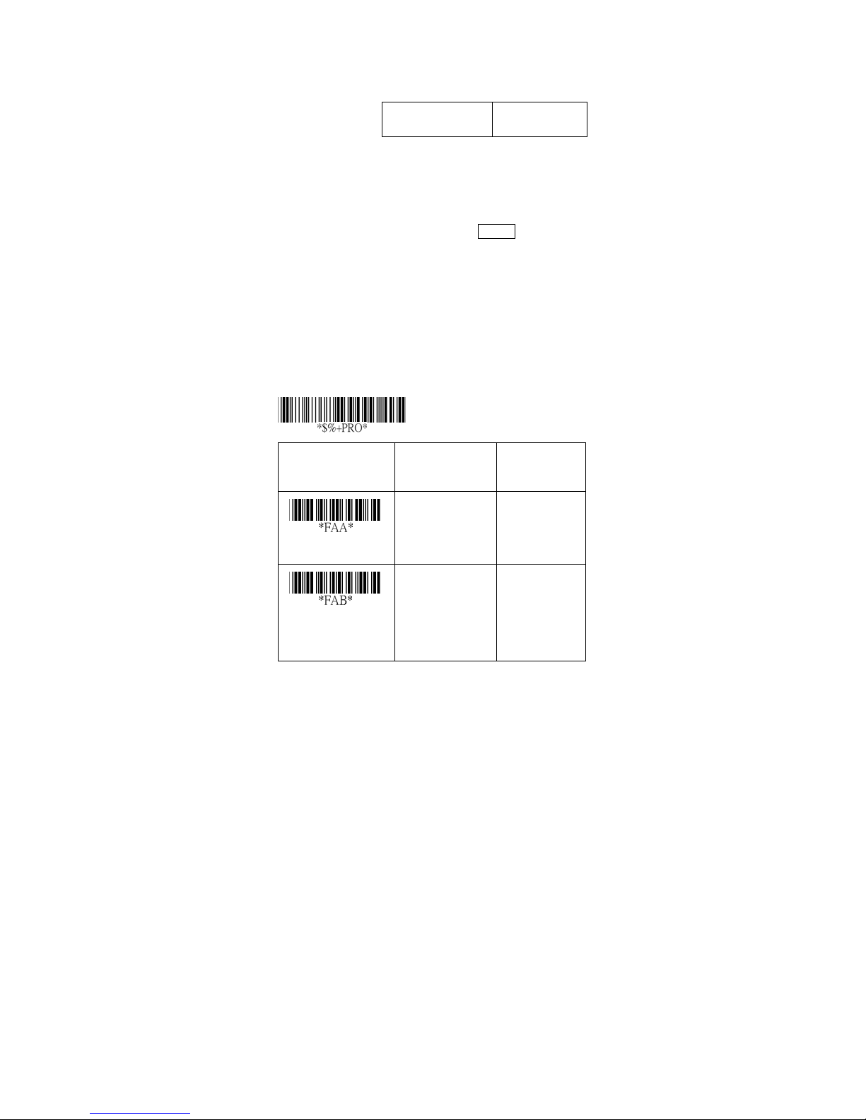
EAN-8
Read: For ma t
Data Digits
(7 Digits)
Check-sum verification: The checksum of EAN-8 is
optional and made as the sum of the numerical value of
the data digits.
Check-sum transmission: By setting Enable, checks sum
will be transmitted.
Truncate leading/ending: Refer to Truncate
leading/ending of UPCA.
Code Id setting: Refer to Code ID setting of UPCA.
Insertion group selection: Refer to Insertion group
selection of UPCA.
Program
Option Bar Code Option Alphanumeric
Check
Digits
Entry
Read
Check-sum
verification
Disable
Enable
Disable
Enable
47
00
01*
00
01*
Page 54
Check-sum
transmission
Disable
Enable
0-15 00-15
00
01*
Truncate leading
0-15 00-15
Tru ncate ending
Two characters
00-ffH ASCII
Code ID setting
Insert group
selection
code
00-44 00-44
00*
00*
00-ffH, 00-ffH
< FF >
*
00
*
Exit
48
Page 55
EAN-8
Supplement digits: Form at
Data
Digits
(7 Digits)
Truncation / Expansion: Refer to Truncate Leading zero
of UPCE.
Expansion: Refer to Expansion of UPCE.
Check
Digits
Supplement Digits
2 or 5 or
UCC/EAN 128
Option Bar Code Option Alphanumeric
Program
Entry
Supplement digits
(For 8110/
8150/8250)
Supplement digits
(For 8310/8312)
None
2 digits
5 digits
UCC/EAN 128
Auto detection
None
2 digits
5 digits
2,5 digits
UCC/EAN 128
2, UCC/EAN
128
5, UCC/EAN
49
00
01
02
03
04
00
01
02
03
04
05
06
07
*
*
Page 56
128
All
Truncation /
Expansion
(For 8110)
Truncation /
Expansion
(For 8150/8250/
8310/8312)
Expansion
Disable
Enable
None
Truncate leading
zero
Expand to
EAN13
Disable
Enable
00
01
00
01
02
00
01
*
*
*
Exit
50
Page 57
Code 39
Read: For ma t
Start
Data Digits
“★”
( Variable)
Check-sum verification: The checksum of Code-39 is
optional and made as the sum module 43 of the
numerical value of the data digits.
Check-sum transmission: By setting Enable, checksum
will be transmitted.
Max./Min. code length: Each symbology has own
Max./Min. Code Length. They can be set to qualify data
entry. If their Max./Min. Code Length is zero, the Global
Min./Max. Code Length is in effect. The length is defined
as to the actual barcode data length to be sent. Label
with length exceeds these limits will be rejected. Make
sure that the Minimum length setting is no greater than
the Maximum length setting, or otherwise all the labels of
the symbology will not be readable. In particular, you can
see the same value for both Minimum and Maximum
reading length to force the fixed length barcode decoded.
Truncate leading/ending: Refer to Truncate
leading/ending of UPCA.
Code Id setting: Refer to Code ID setting of UPCA.
Program
Option Bar Code Option Alphanumeric
Checksum
(Optional)
Entry
End
“★”
Max. code length
00-64 00-64
00*
51
Page 58
Read
Disable
Enable
00
01*
Check-sum
verification
Check-sum
transmission
Min. code length
Truncate leading
Tru ncate ending
Disable
Enable
Disable
Enable
00-64 00-64
0-20 00-20
0-15 00-15
*
00
01
*
00
01
00*
00*
00
*
Code ID setting
00-ffH ASCII
code
00-ffH
<*>
Exit
52
Page 59
Code 39
Insertion group selection: Refer to Insertion group
selection of UPCA.
Format: The Full ASCII Code-39 is an enhanced set of
Code-39 that is the data with total of 128 characters to
represent Full ASCII code. It is combined one of the
digits +, %, $ and/ with one of the alpha digits (A to Z).
Append: This function allows several symbols to be
concatenates and be treat as one single data entry. The
scanner will not transmit the embedded appending code
(space for Code-39). If Enable and other symbols were
read again with the appended code, then codes will be
transmitted without Code ID, Preamble and Prefix. When
a symbol was decoded without the appended code, the
data will be transmitted without Code ID and Prefix, but
the Postamble Suffix codes are appended. This function
is used when the first number of code 39 is a space.
Example: □123456.
Start/end transmission: The start and end characters of
Code-39 are“★”. You can transmit all data digits
including two “★”.
Option Bar Code Option Alphanumeric
Program
Entry
Insert group
00-44 00-44
00
*
53
Page 60
selection
Standard
Full ASCII
Form at
Disable
Enable
Append
Disable
Enable
Start/end
transmission
00
01
00
01
00
01
*
*
*
Exit
54
Page 61
Interleaved 2 of 5
Read: For ma t
Data Digits
(Variable)
Check-sum verification: The checksum is made as the
sum module 10 of the numerical values of all data digits.
Check-sum transmission: By setting Enable, checksum
will be transmitted.
Max./Min. code length: Refer to Max./Min. code length
of Code-39.
Truncate leading/ending: Refer to Truncate
leading/ending of UPCA.
Code Id setting: Refer to Code ID setting of UPCA.
Insertion group selection: Refer to Insertion group
selection of UPCA.
Program
Option Bar Code Option Alphanumeric
Checksum
(Optional)
Entry
Read
Check-sum
verification
Disable
Enable
Disable
Enable
55
00
01*
*
00
01
Page 62
Check-sum
transmission
Disable
Enable
00-64 00-64
00
01
*
Max. code leading
Min. code leading
Truncate leading
Tru ncate ending
Code ID setting
Insert group
selection
00-64 00-64
0-15 00-15
0-15 00-15
00-ffH ASCII
code
00-44 00-44
00*
00*
00
*
00*
00-ffH
< i >*
00
*
Exit
56
Page 63
Industrial 2 of 5
Read: For ma t
Data Digits
(Variable)
Max./Min. code length: Refer to Max./Min. code length
of Code-39.
Truncate leading/ending: Refer to Truncate
leading/ending of UPCA.
Code Id setting: Refer to Code ID setting of UPCA.
Insertion group selection: Refer to Insertion group
selection of UPCA.
Program
Option Bar Code Option Alphanumeric
Checksum
(Optional)
Entry
Read
Max. code length
Min. code length
Disable
Enable
00-64 00-64
00-64 00-64
*
00
01
00*
00
*
57
Page 64
0-15 00-15
Truncate leading
Tru ncate ending
Code ID setting
Insert group
selection
0-15 00-15
00-ffH ASCII
code
00-44 00-44
00*
00
*
00-ffH
< i >*
00
*
Exit
58
Page 65
Matrix 2 of 5 Eur
Read: For ma t
Data Digits
(Variable)
Checksum Verification: The checksum is made as the
sum module 10 of the numerical values of all data digits.
Checksum Transmission: By setting Enable, checksum
will be transmitted.
Max./Min. code length: Refer to Max./Min. code length
of Code-39.
Truncate leading/ending: Refer to Truncate
leading/ending of UPCA.
Code Id setting: Refer to Code ID setting of UPCA.
Insertion group selection: Refer to Insertion group
selection of UPCA.
Option Bar Code Option Alphanumeric
Program
Checksum
(Optional)
Entry
Read
Checksum
Verifi cation
Disable
Enable
Disable
Enable
59
00
01
00
01
*
*
Page 66
Checksum
Transmission
Disable
Enable
00-64 00-64
00
01
*
Max. code length
Min. code length
Truncate leading
Tru ncate ending
Code ID setting
Insert group
selection
00-64 00-64
0-15 00-15
0-15 00-15
00-ffH ASCII
code
00-44 00- 44
00*
00*
00
*
00*
00-ffH
< B >*
00
*
Exit
60
Page 67
Codabar
Read: For ma t
Start Data Digits (Variable)
Checksum Verification: The checksum is made as the
sum module 16 of the numerical values of all data digits.
Checksum Transmission: By setting Enable, checksum
will be transmitted.
Max./Min. code length: Refer to Max./Min. code length
of Code-39.
Truncate leading/ending: Refer to Truncate
leading/ending of UPCA.
Code Id setting: Refer to Code ID setting of UPCA.
Option Bar Code Option Alphanumeric
Program
Checksum
(Optional)
Entry
End
Read
Checksum
Verifi cation
Disable
Enable
Disable
Enable
61
00
*(8150/8250
/8310/8312)
*(8110)
01
00
*
01
Page 68
Checksum
Transmission
Max. code length
Min. code length
Truncate leading
Tru ncate ending
Disable
Enable
00-64 00-64
00-64 00-64
0-15 00-15
0-15 00-15
00
01
00
00
00
00
*
*
*
*
*
Code ID setting
00-ffH ASCII
code
62
00-ffH
< % >
*
Exit
Page 69
Codabar
Insertion group selection: Refer to Insertion group
selection of UPCA.
Start/End type: The Codabar has four pairs of Start/End
pattern; you may select one pair to match your
application.
Start/End Transmission: Refer to Start/End
Transmission of Code 39.
Option Bar Code Option Alphanumeric
Insert group
selection
Program
Entry
00-44 00-44
00
*
Start/End type
Start/End
transmission
ABCD/ABCD
abcd/abcd
ABCD/TN*E
Abcd/tn*e
Disable
Enable
63
00
01
02
03
00
01
*
*
Exit
Page 70
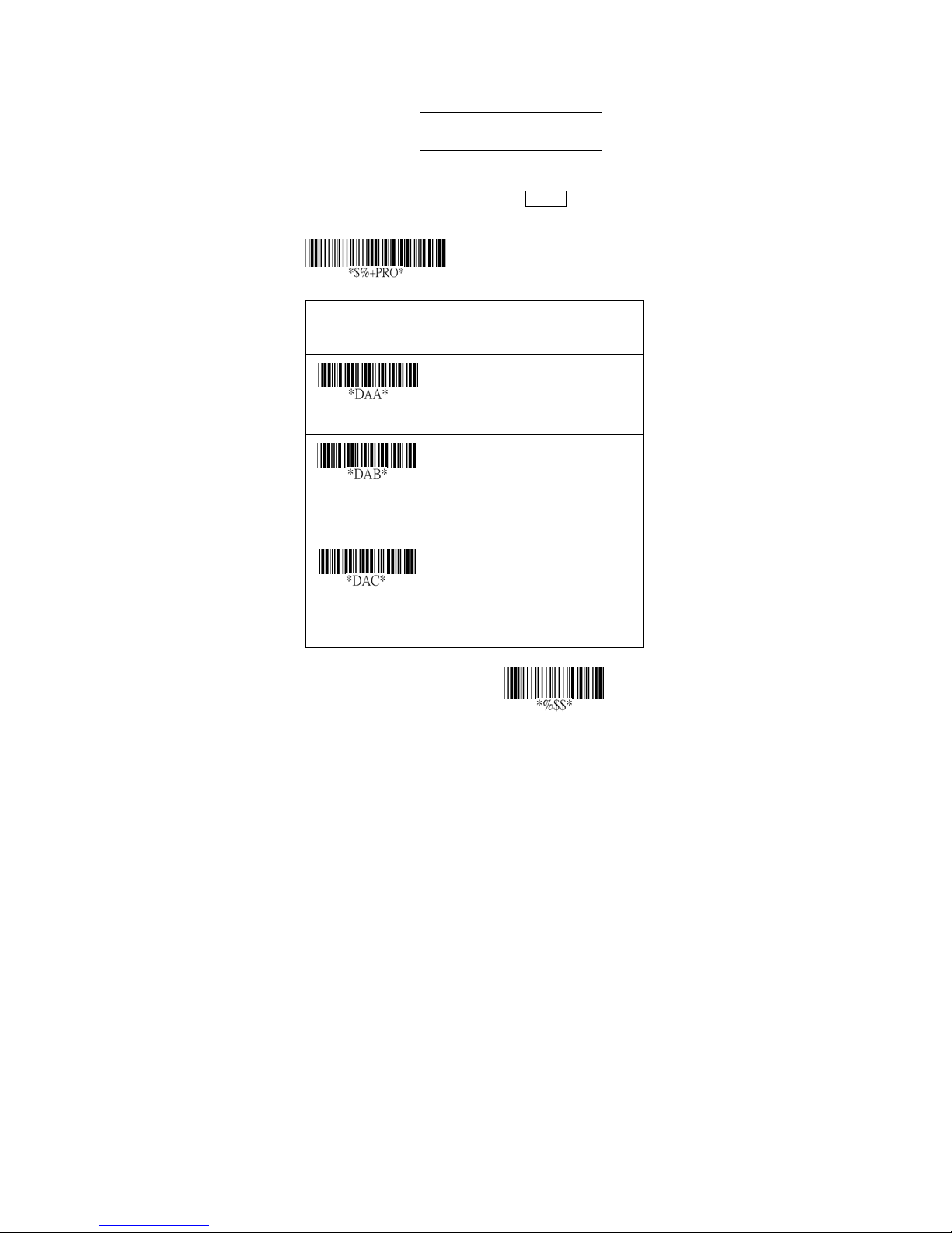
Code-128
Read: For ma t
Data Digits
(Variable)
Checksum Verification: The checksum is made as the
sum module 103 of all data digits.
Checksum Transmission: By setting Enable, checksum
will be transmitted.
Option Bar Code Option Alphanumeric
Program
Checksum
(Optional)
Entry
Read
Checksum
Verifi cation
Checksum
Transmission
Disable
Enable
Disable
Enable
Disable
Enable
64
00
01
00
01
00
01
*
*
*
Exit
Page 71
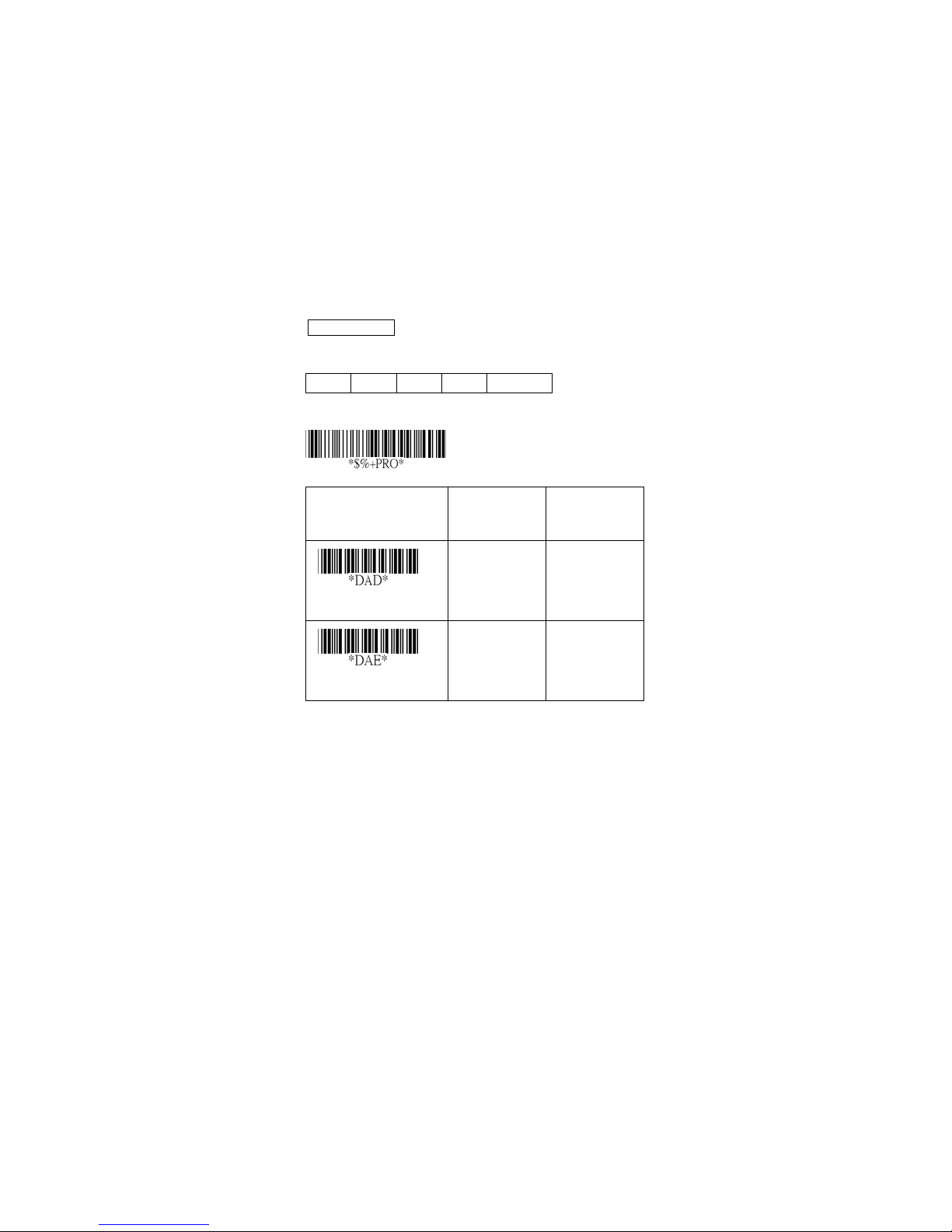
Code-128
Max./Min. code length: Refer to Max./Min. code length
of Code-39.
Truncate leading/ending: Refer to Truncate
leading/ending of UPCA.
Code Id setting: Refer to Code ID setting of UPCA.
Insertion group selection: Refer to Insertion group
selection of UPCA.
Format: The Code-128 can be translated to
UCC/EAN-128 format if it starts with FNC1 character.
The first FNC1 will be translated to “]C1”,and next to be a
field separator code as <GS>(1D
]C1 Data <GS> Data Checksum
Option Bar Code Option Alphanumeric
Program
16).
Entry
Max. code length
Min. code length
00-64 00-64
00-64 00-64
00
00
65
*
*
Page 72
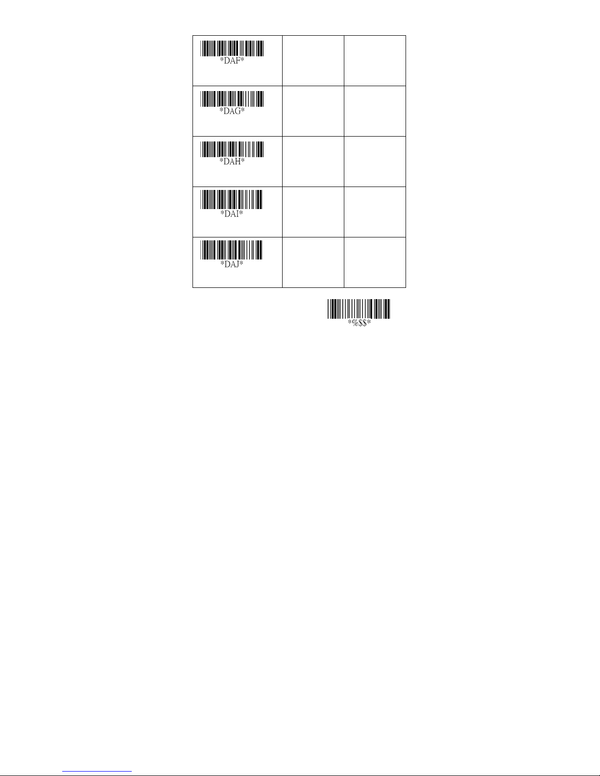
Truncate leading
Tru ncate ending
0-15 00-15
0-15 00-15
00
00
*
*
Code ID setting
Insert group selection
Form at
00-ffH ASCII
code
00-44 00-44
Standard
UCC/EAN-12
8
00-ffH
< # >
00
00
01
*
*
*
Exit
66
Page 73
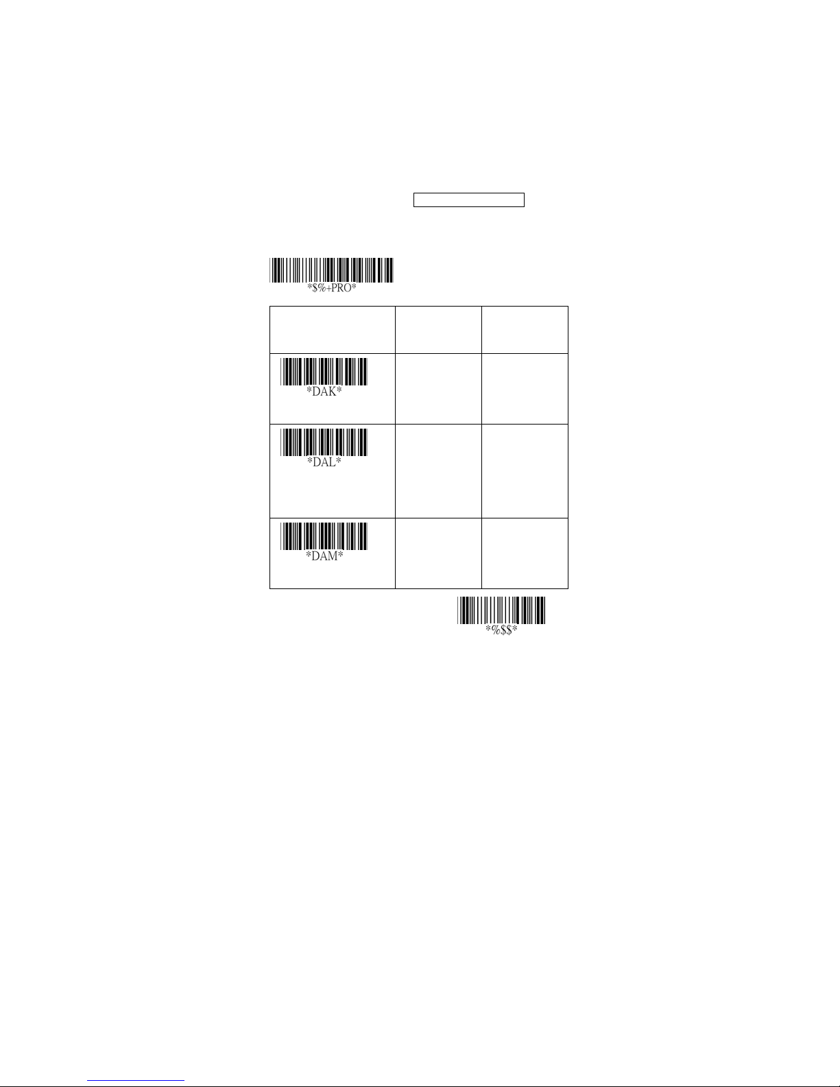
Code-128
Append: When the function is enabled, it won't show the
data immediately if scanner read the barcode includes
FNC2 code. It will show all data until it read the barcode,
which doesn't have FNC2 code.
UCC/ EAN 128 ID setting: To set tin g the c ode I D fo r
UCC/EAN-128 output format.
Field separator code: This feature is only used for
UCC/EAN-128 format. This Field separator code means
you can reassign second or after a FNC1 for your usage.
The default of ASCII code is <GS>(1D
16).
Option Bar Code Option Alphanumeric
Program
Entry
Append
UCC/EAN-128
ID setting
Field separator code
Disable
Enable
00-ffH ASCII
code
00-ffH ASCII
code
67
*
00
01
00-ffH
< # >
00-ffH
1DH
*
*
Exit
Page 74
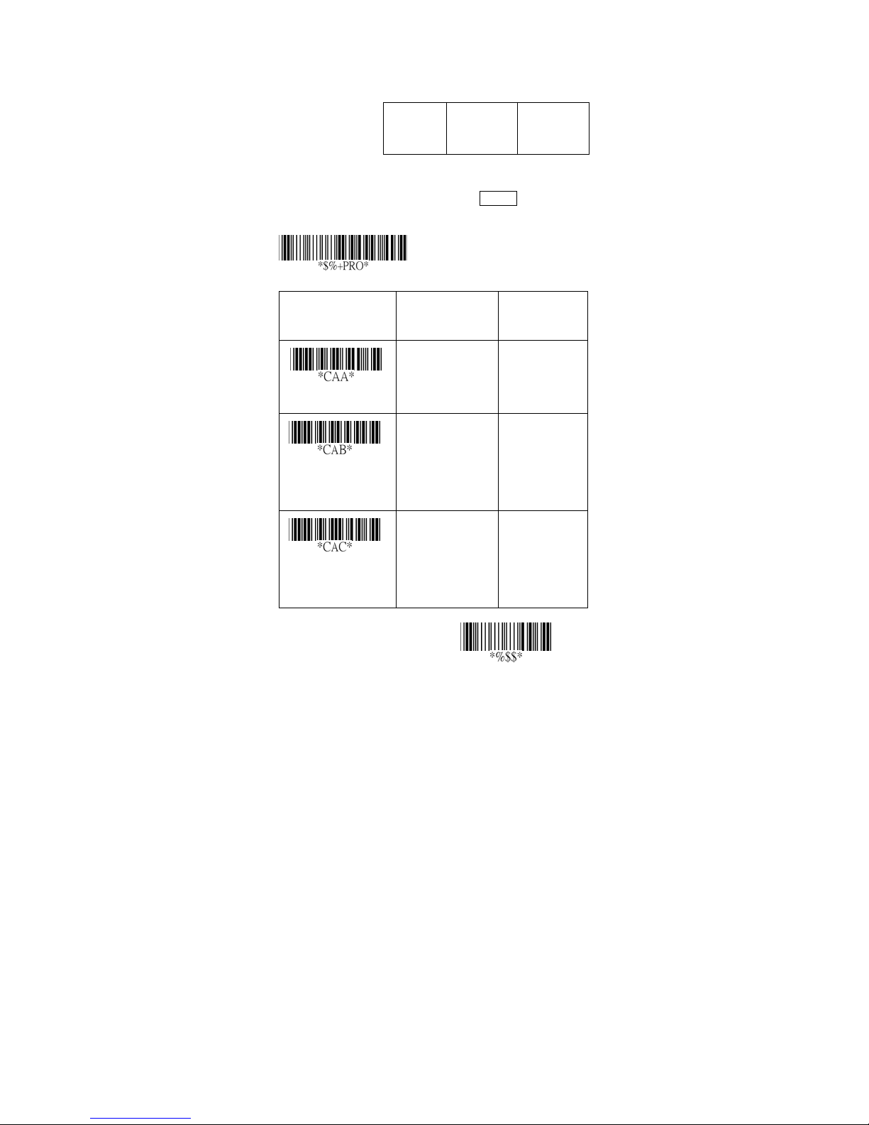
Code-93
Read: For ma t
Data
Digits
(Variable)
Checksum Verification: The checksum is made as the
sum module 47 of the numerical values of all data digits.
Checksum Transmission: By setting Enable, checksum
will be transmitted.
Option Bar Code Option Alphanumeric
Program
Checksum1
(Optional)
Checksum2
(Optional)
Entry
Read
Checksum
Verifi cation
Checksum
Transmission
Disable
Enable
Disable
Enable
(two digits)
Disable
Enable
68
00
01
00
01
00
01
*
*
*
Exit
Page 75
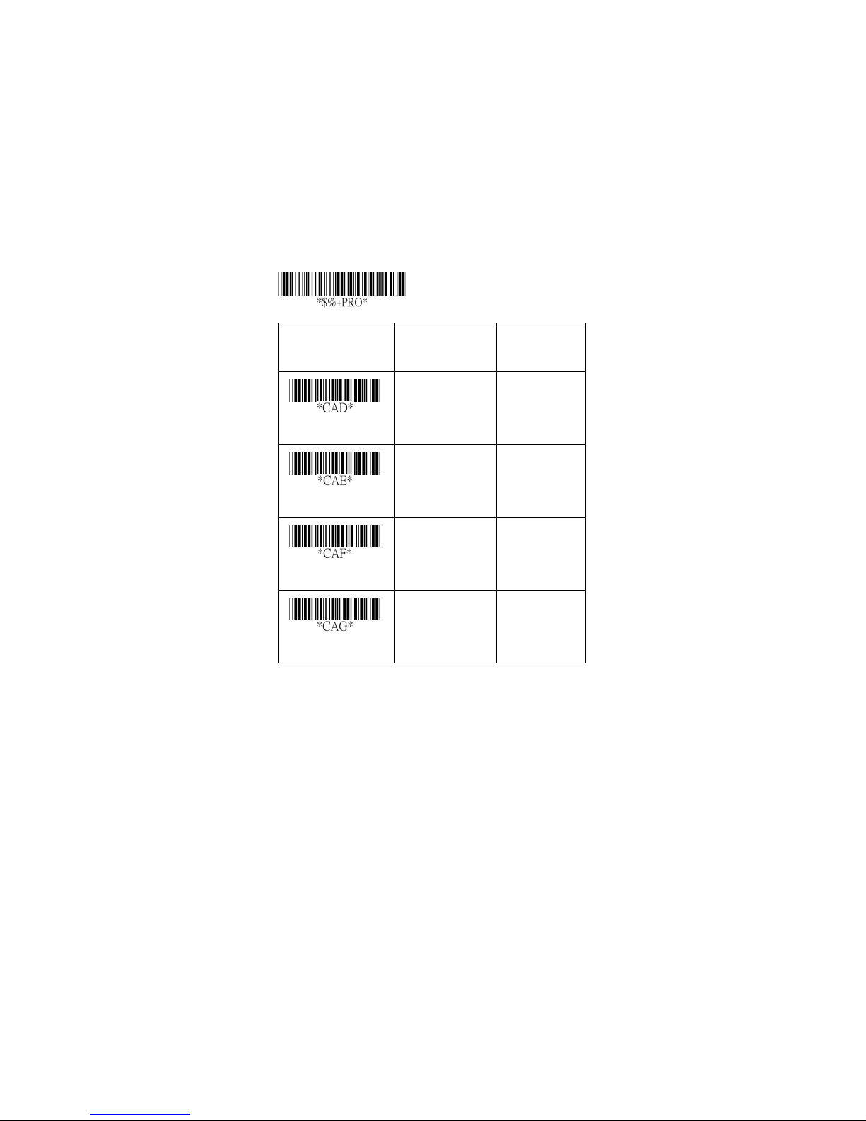
Code-93
Max./Min. code length: Refer to Max./Min. code length
of Code-39.
Truncate leading/ending: Refer to Truncate
leading/ending of UPCA.
Code Id setting: Refer to Code ID setting of UPCA.
Insertion group selection: Refer to Insertion group
selection of UPCA.
Option Bar Code Option Alphanumeric
Max. code length
Program
Entry
00-64 00-64
00
00-64 00-64
*
Min. code length
Truncate leading
Tru ncate ending
00
00
00
*
*
*
0-15 00-15
0-15 00-15
69
Page 76

Code ID setting
Insert group
selection
00-ffH ASCII
code
00-44 00-44
00-ffH
< & >
00
*
*
Exit
70
Page 77
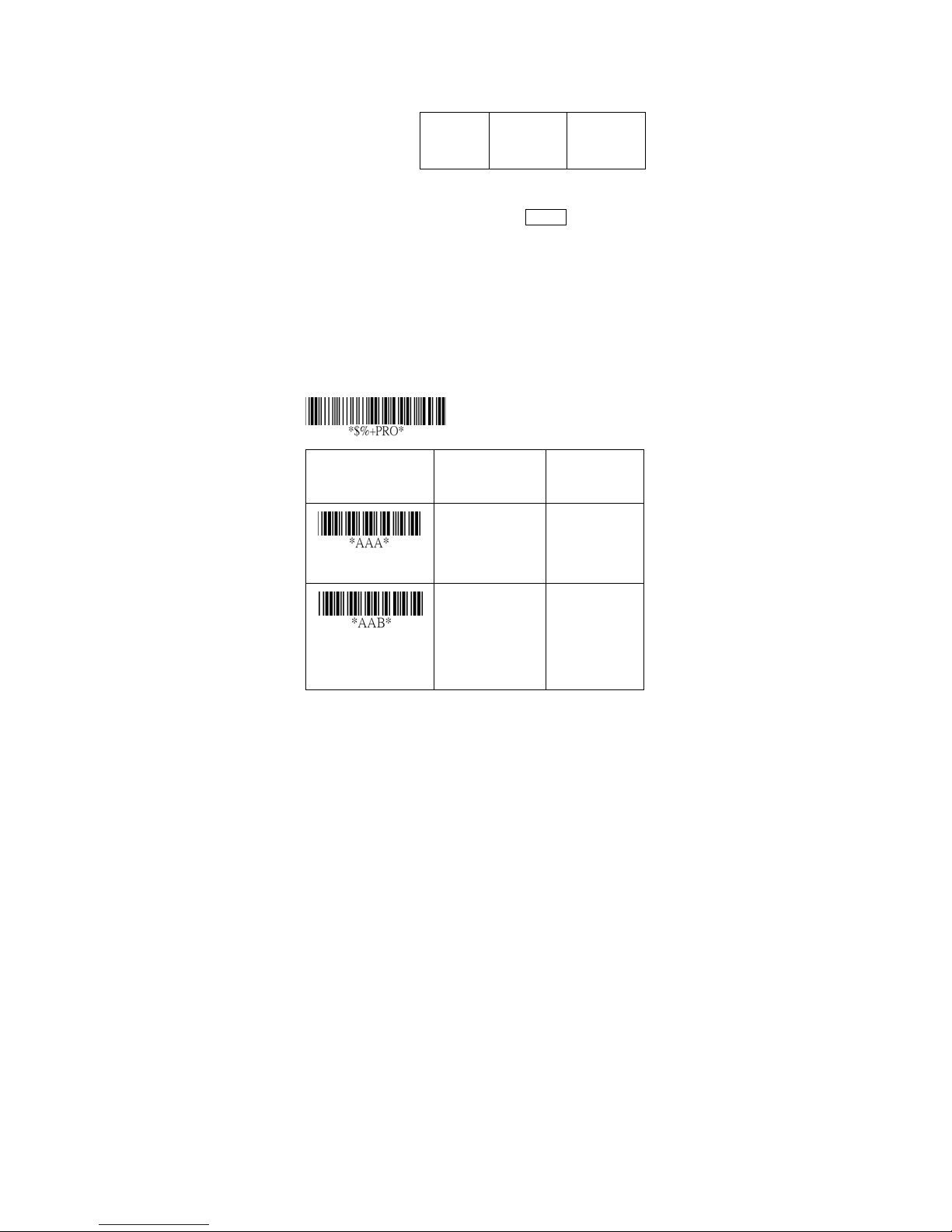
Code-11
Read: For ma t
Data
Digits
(Variable)
Checksum Verification: The checksum is presented as
the sum module 11 of all data digits.
Checksum Transmission: By setting Enable, checksum1
and checksum2 will be transmitted upon your selected
checksum verification method.
Max./Min. code length: Refer to Max./Min. code length
of Code-39.
Truncate leading/ending: Refer to Truncate
leading/ending of UPCA.
Code Id setting: Refer to Code ID setting of UPCA.
Insertion group selection: Refer to Insertion group
selection of UPCA.
Option Bar Code Option Alphanumeric
Program
Checksum1
(Optional)
Checksum2
(Optional)
Entry
Disable
Enable
Read
Disable
One digit
Checksum
Verifi cation
Two digits
71
00
01
00
01
02
*
*
Page 78
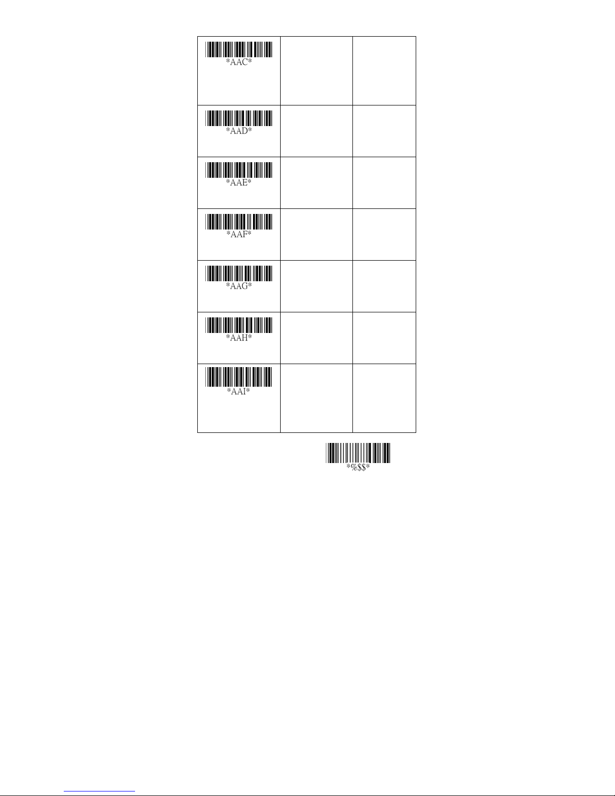
Checksum
Transmission
Max. code length
Min. code length
Truncate leading
Tru ncate ending
Disable
Enable
00-64 00-64
00-64 00-64
0-15 00-15
0-15 00-15
00
01
00
00
00
00
*
*
*
*
*
Code ID setting
Insert group
selection
00-ffH ASCII
code
00-44 00-44
00-ffH
< O >
*
00
*
72
Exit
Page 79
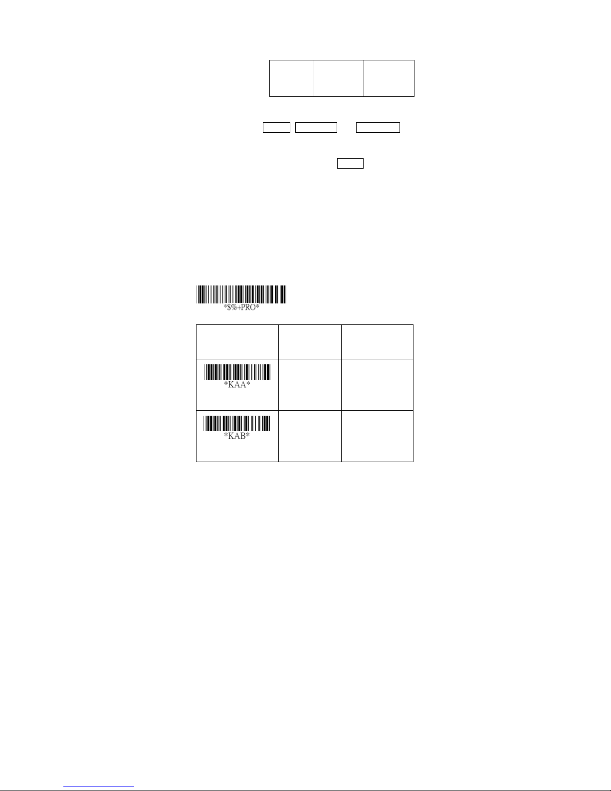
MSI/plessey
Read: For ma t
Data
Digits
(Variable)
Checksum Verification: The MSI/Plessey has one or two
optional checksum digits. The checksum is presented 3
kinds of method Mod10, Mod10/10 and Mod 11/10.
The checksum1 and checksum2 will be calculated as the
sum module 10 or 11 of the data digits.
Checksum Transmission: By setting Enable, checksum1
and checksum2 will be transmitted upon your selected
checksum verification method.
Max./Min. code length: Refer to Max./Min. code length
of Code-39.
Truncate leading/ending: Refer to Truncate
leading/ending of UPCA.
Code Id setting: Refer to Code ID setting of UPCA.
Insertion group selection: Refer to Insertion group
selection of UPCA.
Option Bar Code Option Alphanumeric
Program
Checksum1
(Optional)
Checksum2
(Optional)
Entry
Read
Checksum
Disable
Enable
Disable
Mod 10
73
*
00
01
00
*(8110)
01
*(8150/8250
/8310/8312)
Page 80
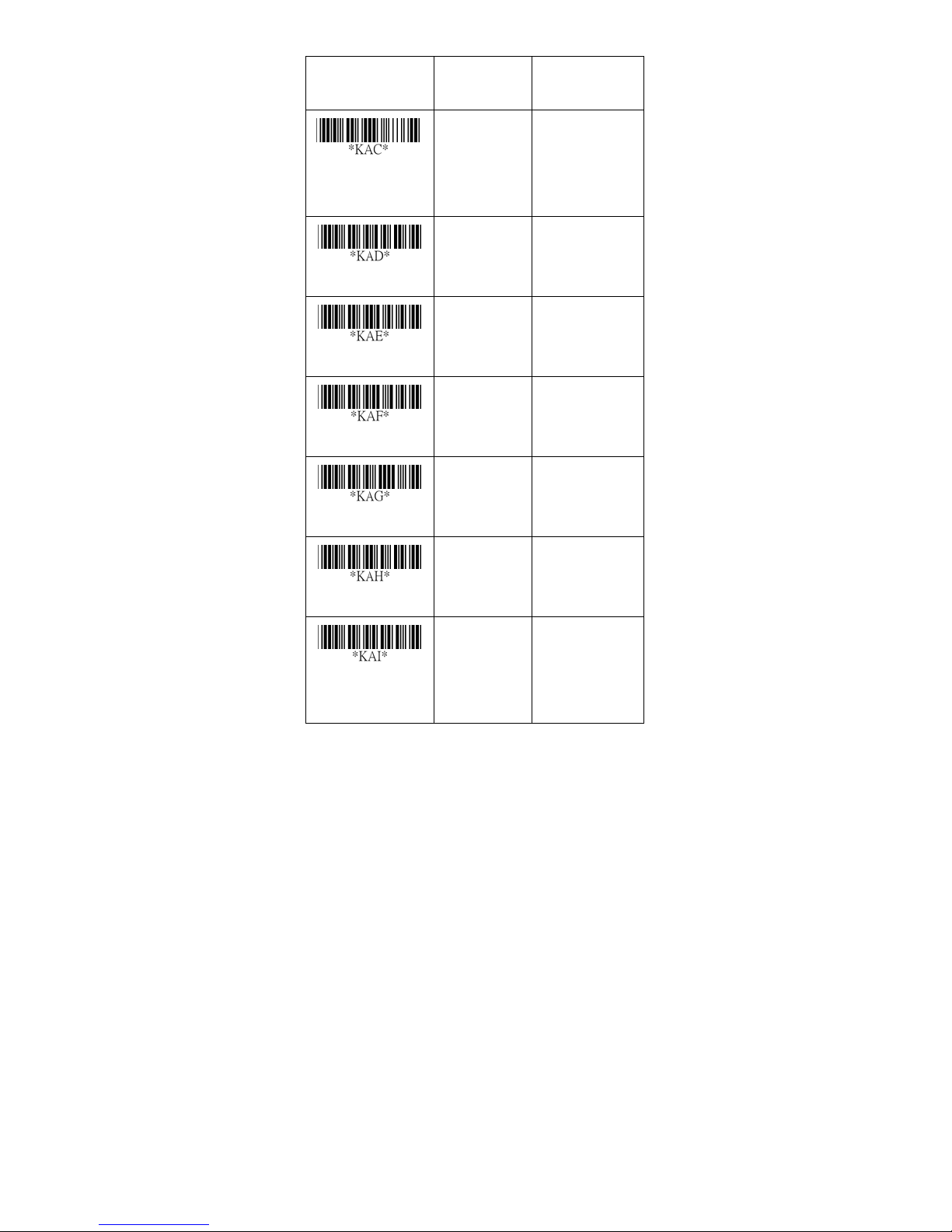
Verification Mod 10/10
Mod 11/10
02
03
Checksum
Transmission
Max. code length
Min. code length
Truncate leading
Tru ncate ending
Code ID setting
Disable
Enable
00-64 00-64
00-64 00-64
0-15 00-15
0-15 00-15
00-ffH ASCII
code
00
*
01
*
00
00
*
00
*
*
00
00-ffH
< @ >
*
Insert group
selection
00-44 00-44
00
*
74
Page 81

Exit
75
Page 82
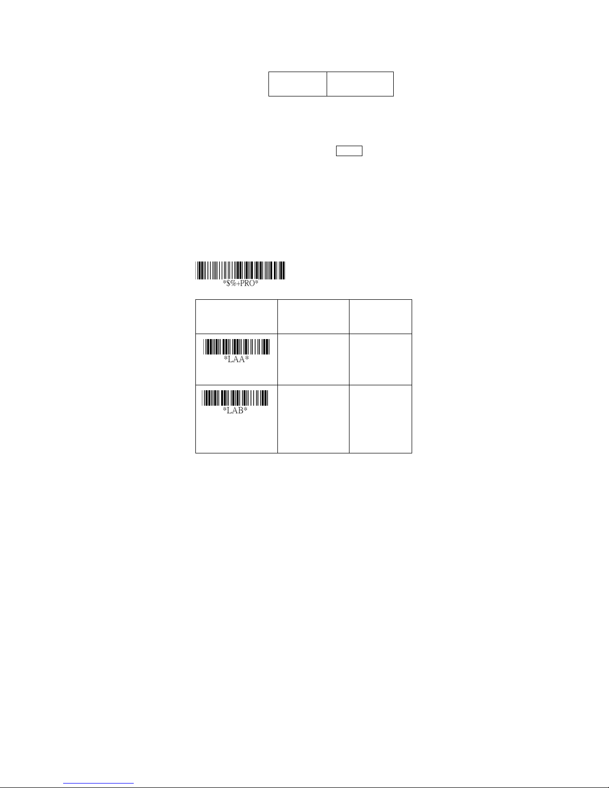
UK/plessey
Read: For ma t
Data Digits
(Variable)
Checksum Verification: The UK/Plessey has one or two
optional checksum digits. The checksum1 and
checksum2 will be calculated as the sum module 10 or
11 of the data digits.
Checksum Transmission: By setting Enable, checksum
will be transmitted.
Max./Min. code length: Refer to Max./Min. code length
of Code-39.
Truncate leading/ending: Refer to Truncate
leading/ending of UPCA.
Code Id setting: Refer to Code ID setting of UPCA.
Insertion group selection: Refer to Insertion group
selection of UPCA.
Option Bar Code Option Alphanumeric
Program
Checksum1+2
(Optional)
Entry
Read
Checksum
Verifi cation
Disable
Enable
Disable
Enable
76
00
01
00
01
*
*
Page 83
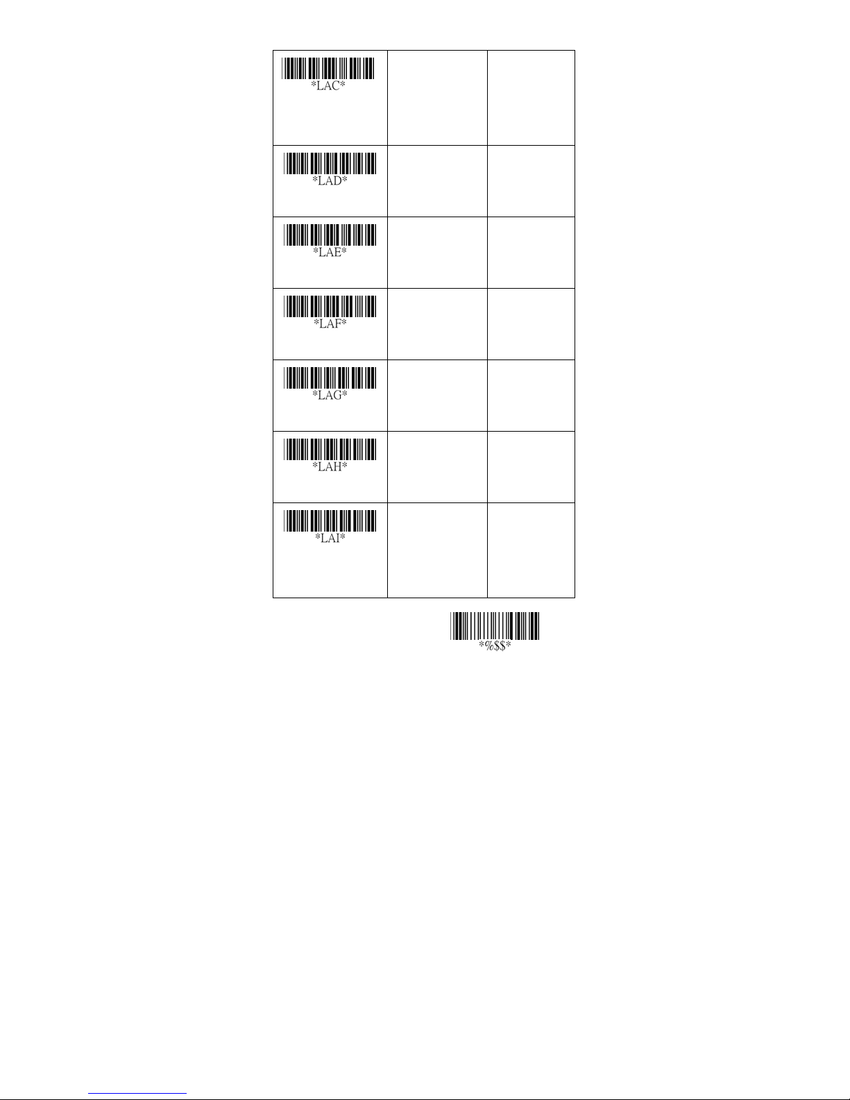
Checksum
Transmission
Max. code length
Min. code length
Truncate leading
Tru ncate ending
Disable
Enable
00-64 00-64
00-64 00-64
0-15 00-15
0-15 00-15
00
01
00
00
00
00
*
*
*
*
*
Code ID setting
Insert group
selection
00-ffH ASCII
code
00-44 00-44
00-ffH
< @ >
00
*
*
77
Exit
Page 84
Tele pen
Read: IATA (International Air Transport Association).
Checksum Verification: The checksum is presented as
the sum module 10 or 11 of the data digits.
Checksum Transmission: By setting Enable, checksum
will be transmitted.
Max./Min. code length: Refer to Max./Min. code length
of Code-39.
Truncate leading/ending: Refer to Truncate
leading/ending of UPCA.
Code Id setting: Refer to Code ID setting of UPCA.
Insertion group selection: Refer to Insertion group
selection of UPCA.
Option Bar Code Option Alphanumeric
Program
Entry
Read
Checksum
Verifi cation
Checksum
Transmission
Disable
Enable
Disable
Enable
Disable
Enable
78
00
01
00
01
00
01
*
*
*
Page 85
Max. code length
Min. code length
Truncate leading
Tru ncate ending
00-64 00-64
00
00
00
00
*
*
*
*
00-64 00-64
0-15 00-15
0-15 00-15
Code ID setting
Insert group
selection
Format
00-ffH ASCII
code
00-44 00-44
Numeric only
Full ASCII only
00-ffH
< S >
00
*
00
*
01
*
79
Exit
Page 86
Standard 2 of 5
Read: For ma t
Data Digits
(Variable)
Check-sum verification: The checksum is made as the
sum module 10 of the numerical values of all data digits.
Check-sum transmission: By setting Enable, checksum
will be transmitted.
Max./Min. code length: Refer to Max./Min. code length
of Code-39.
Truncate leading/ending: Refer to Truncate
leading/ending of UPCA.
Code Id setting: Refer to Code ID setting of UPCA.
Insertion group selection: Refer to Insertion group
selection of UPCA.
Option Bar Code Option Alphanumeric
Program
Checksum1
(Optional)
Entry
Read
*JAB*
Check-sum
verification
Disable
Enable
Disable
Enable
80
*
00
01
00*
01
Page 87
*JAC*
Check-sum
transmission
Max. code length
Min. code length
Truncate leading
Tru ncate ending
Disable
Enable
00-64 00-64
00-64 00-64
0-15 00-15
0-15 00-15
00
01
00
00
00
00
*
*
*
*
*
Code ID setting
Insert group
selection
00-ffH ASCII
code
00-44 00-44
00-ffH
< i >
*
00
*
81
Exit
Page 88
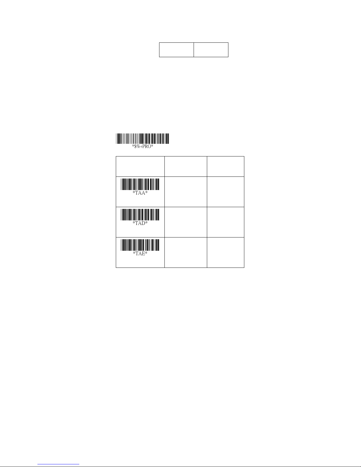
RSS-14
Read: For ma t
Data Digits
(Variable)
Max./Min. code length: Refer to Max./Min. code length
of Code-39.
Truncate leading/ending: Refer to Truncate
leading/ending of UPCA.
Code Id setting: Refer to Code ID setting of UPCA.
Insertion group selection: Refer to Insertion group
selection of UPCA.
UCC/EAN 128 emulation: Refer to Transmiss ion, Cod e
ID transmission must be set as AIM ID enable. Then ]C1
will be identified as prefix of barcode data transmission.
Checksum1
(Optional)
Program
Option Bar Code Option Alphanumeric
Entry
Read
Max. code length
Min. code length
Disable
Enable
00-64 00-64
00-64 00-64
00
01
64
01
*
*
*
82
Page 89
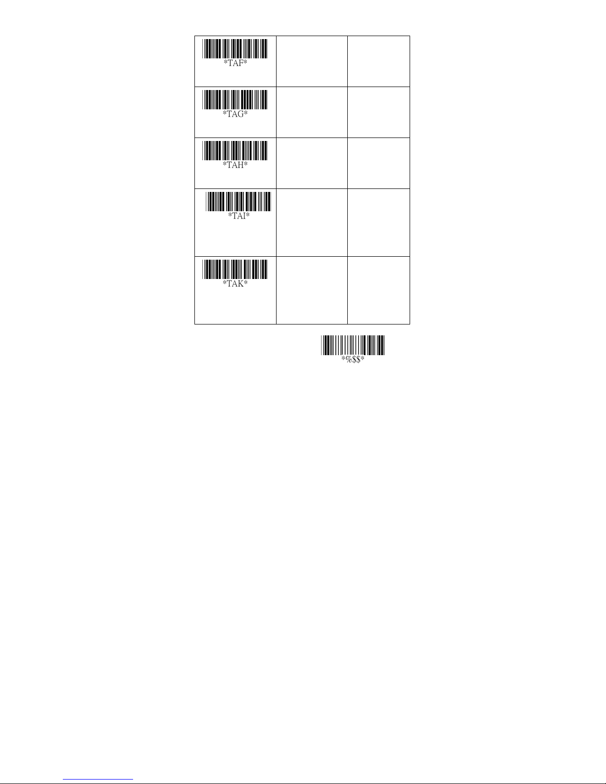
Truncate leading
Tru ncate ending
0-15 00-15
00
00
*
*
0-15 00-15
Code ID setting
Insert group
selection
UCC/EAN128
emulation
00-ffH ASCII
code
00-44 00-44
Disable
Enable
00-ffH
< R4 >
00
*
00
*
01
*
83
Exit
Page 90
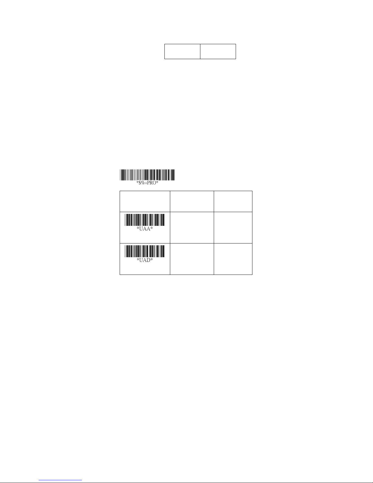
RSS-Limited
Read: For ma t
Data Digits
(Variable)
Max./Min. code length: Refer to Max./Min. code length
of Code-39.
Truncate leading/ending: Refer to Truncate
leading/ending of UPCA.
Code Id setting: Refer to Code ID setting of UPCA.
Insertion group selection: Refer to Insertion group
selection of UPCA.
UCC/EAN 128 emulation: Refer to UCC/EAN 128
emulation of RSS-14.
Checksum1
(Optional)
Option Bar Code Option Alphanumeric
Program
Entry
Read
Max. code length
Disable
Enable
00-64 00-64
00
01
64
*
*
84
Page 91
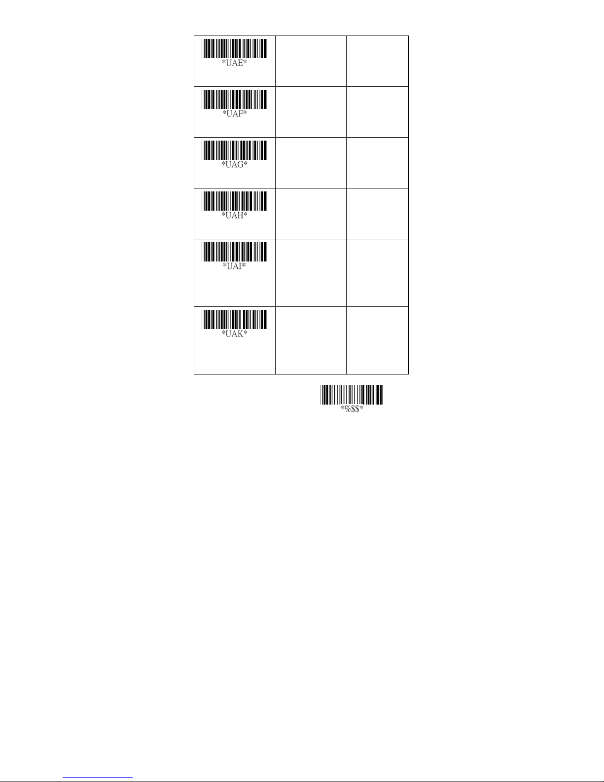
Min. code length
Truncate leading
Tru ncate ending
00-64 00-64
01
00
00
*
*
*
0-15 00-15
0-15 00-15
Code ID setting
Insert group
selection
UCC/EAN128
emulation
00-ffH ASCII
code
00-44 00-44
Disable
Enable
00-ffH
< RL >
00
*
00
*
01
*
85
Exit
Page 92
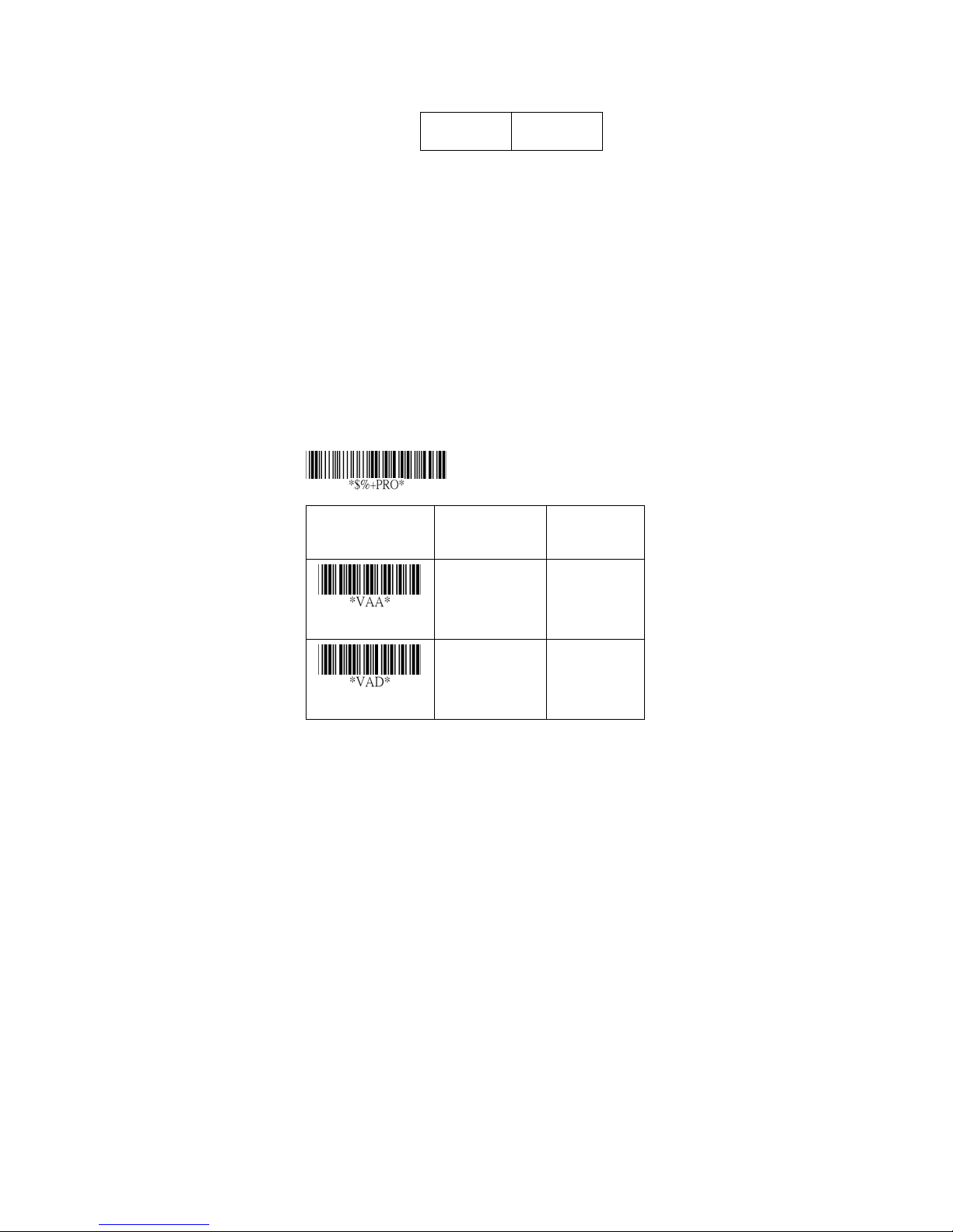
RSS-Expanded
Read: For ma t
Data Digits
(Variable)
Max./Min. code length: Refer to Max./Min. code length
of Code-39.
Truncate leading/ending: Refer to Truncate
leading/ending of UPCA.
Code Id setting: Refer to Code ID setting of UPCA.
Insertion group selection: Refer to Insertion group
selection of UPCA.
UCC/EAN 128 emulation: Refer to UCC/EAN 128
emulation of RSS-14.
Checksum1
(Optional)
Option Bar Code Option Alphanumeric
Program
Entry
Read
Max. code length
Disable
Enable
00-99 00-99
00
01
99
*
*
86
Page 93
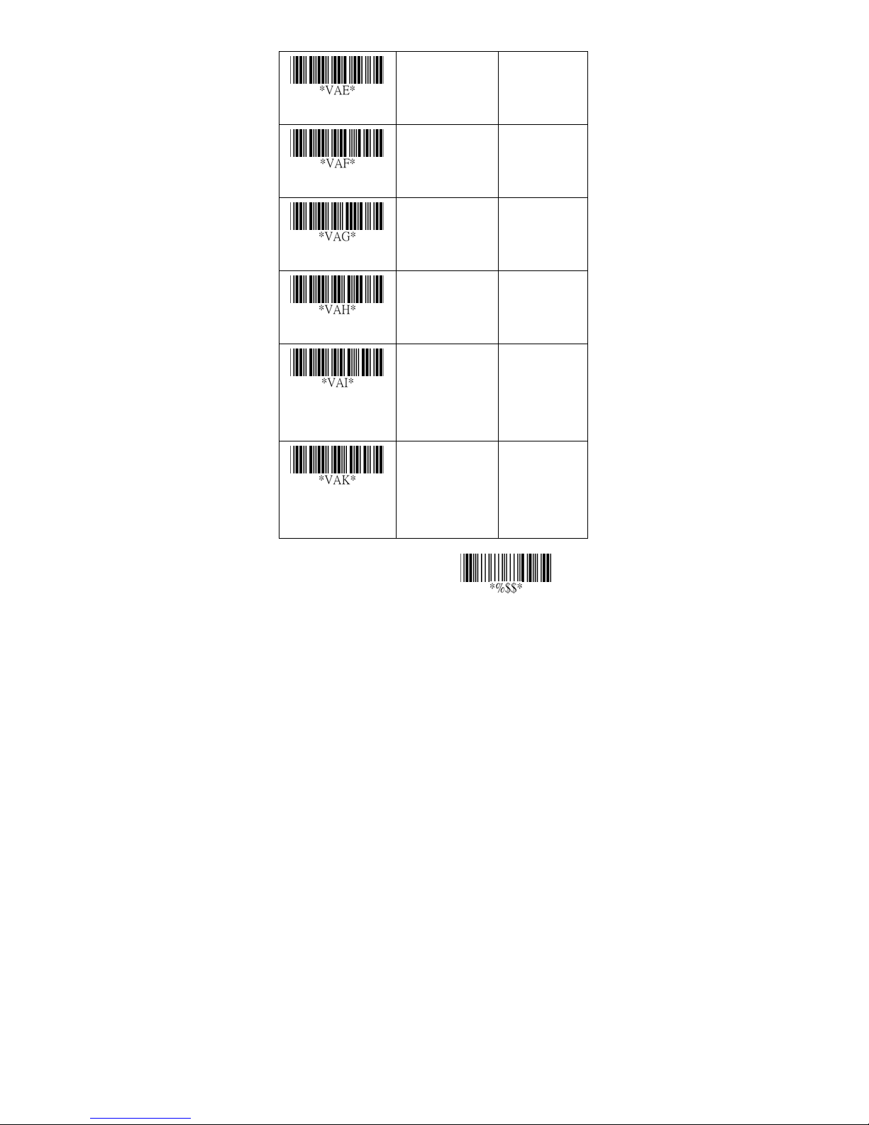
Min. code length
Truncate leading
Tru ncate ending
00-99 00-99
01
00
00
*
*
*
0-15 00-15
0-15 00-15
Code ID setting
Insert group
selection
UCC/EAN128
emulation
00-ffH ASCII
code
00-44 00-44
Disable
Enable
00-ffH
< RX >
00
*
00
*
01
*
87
Exit
Page 94
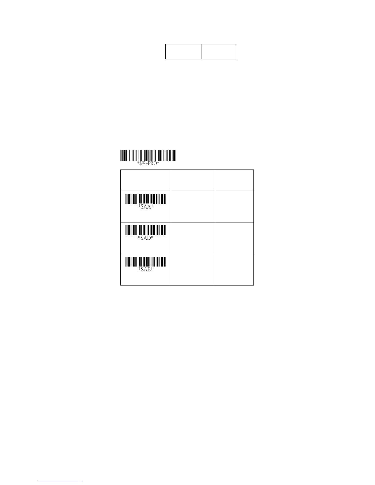
China Post
Read: For ma t
Data Digits
(Variable)
Max./Min. code length: Refer to Max./Min. code length
of Code-39.
Truncate leading/ending: Refer to Truncate
leading/ending of UPCA.
Code Id setting: Refer to Code ID setting of UPCA.
Insertion group selection: Refer to Insertion group
selection of UPCA.
Checksum1
(Optional)
Option Bar Code Option Alphanumeric
Program
Entry
Read
Max. code length
Min. code length
Disable
Enable
00-64
00-64
88
*
00
01
00-64
11
*
00-64
11
*
Page 95
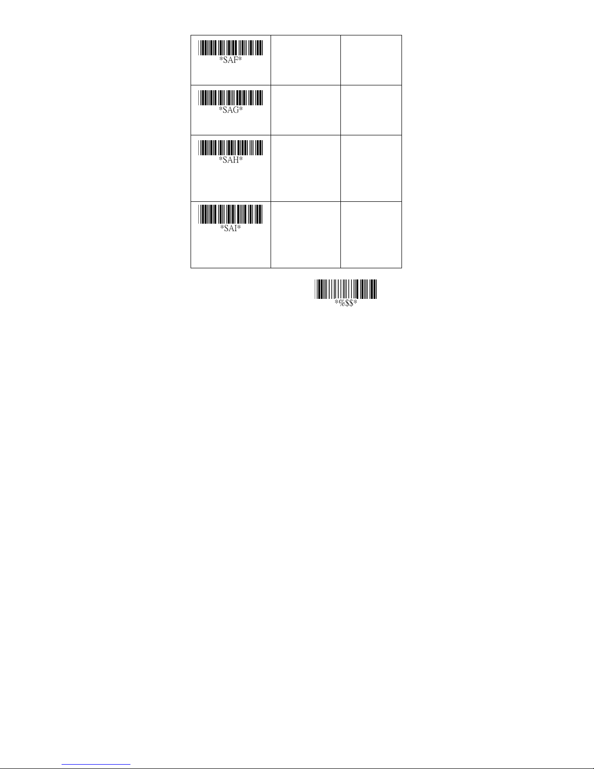
Truncate leading
0-15
00-15
00
*
Tru ncate ending
Code ID setting
Insert group
selection
0-15
00-ffH ASCII
code
00-44
00-15
00
*
00-ffH
< t >
*
01-44
00
*
Exit
89
Page 96
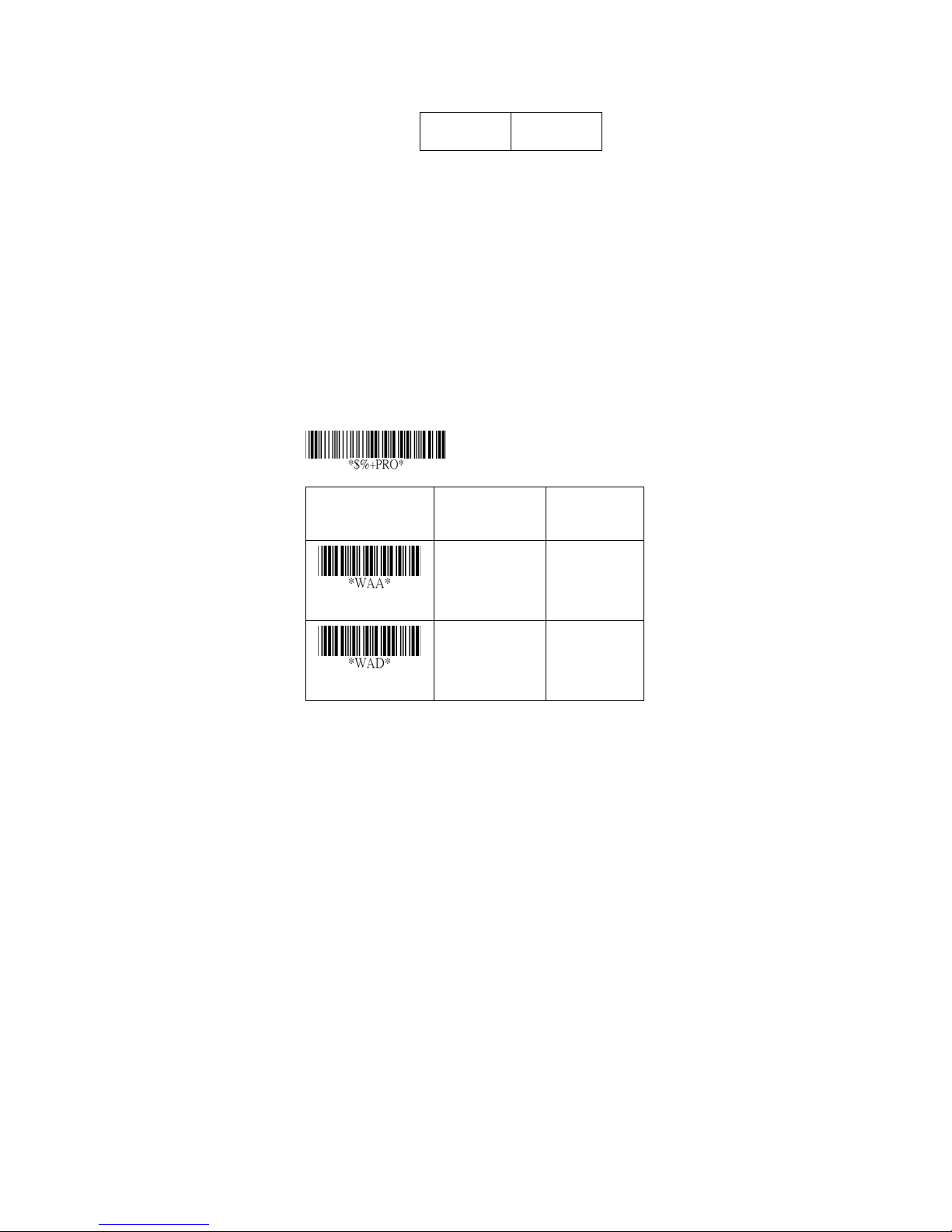
Italian Pharmacode
Read: For ma t
Data Digits
(Variable)
Max./Min. code length: Refer to Max./Min. code length
of Code-39.
Truncate leading/ending: Refer to Truncate
leading/ending of UPCA.
Code Id setting: Refer to Code ID setting of UPCA.
Insertion group selection: Refer to Insertion group
selection of UPCA.
Leading “A”: If this function is enabled, each prefix of
data shall be A.
Checksum1
(Optional)
Program
Option Bar Code Option Alphanumeric
Entry
Read
Max. code length
Disable
Enable
00-64
90
*
00
01
00-64
12
*
Page 97
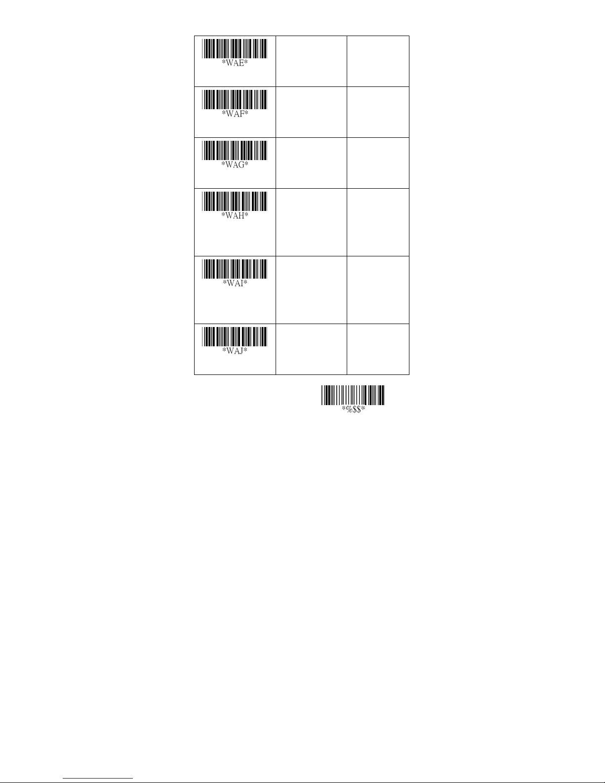
Min. code length
00-64
00-64
09
*
Truncate leading
Tru ncate ending
Code ID setting
Insert group
selection
Leading “A”
0-15
0-15
00-ffH ASCII
code
00-44
Disable
Enable
00-15
00
*
00-15
*
00
01-ffH
< p >
*
00-44
00
*
00
*
01
Exit
91
Page 98
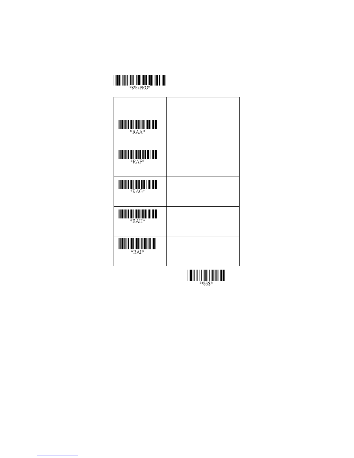
Code-16K
Only the 8250 / 8312 can decode Code-16K.
Truncate leading/ending: Refer to Truncate
leading/ending of UPCA.
Code Id setting: Refer to Code ID setting of UPCA.
Insertion group selection: Refer to Insertion group
selection of UPCA.
Option Bar Code Option Alphanumeric
Program
Entry
Read
Truncate leading
Tru ncate ending
Code ID setting
Insert group selection
Disable
Enable
0-15 00-15
0-15 00-15
00-ffH ASCII
code
00-44 00-44
00
01
00
00
00-ffH
< >
00
92
*
*
*
*
*
Exit
Page 99
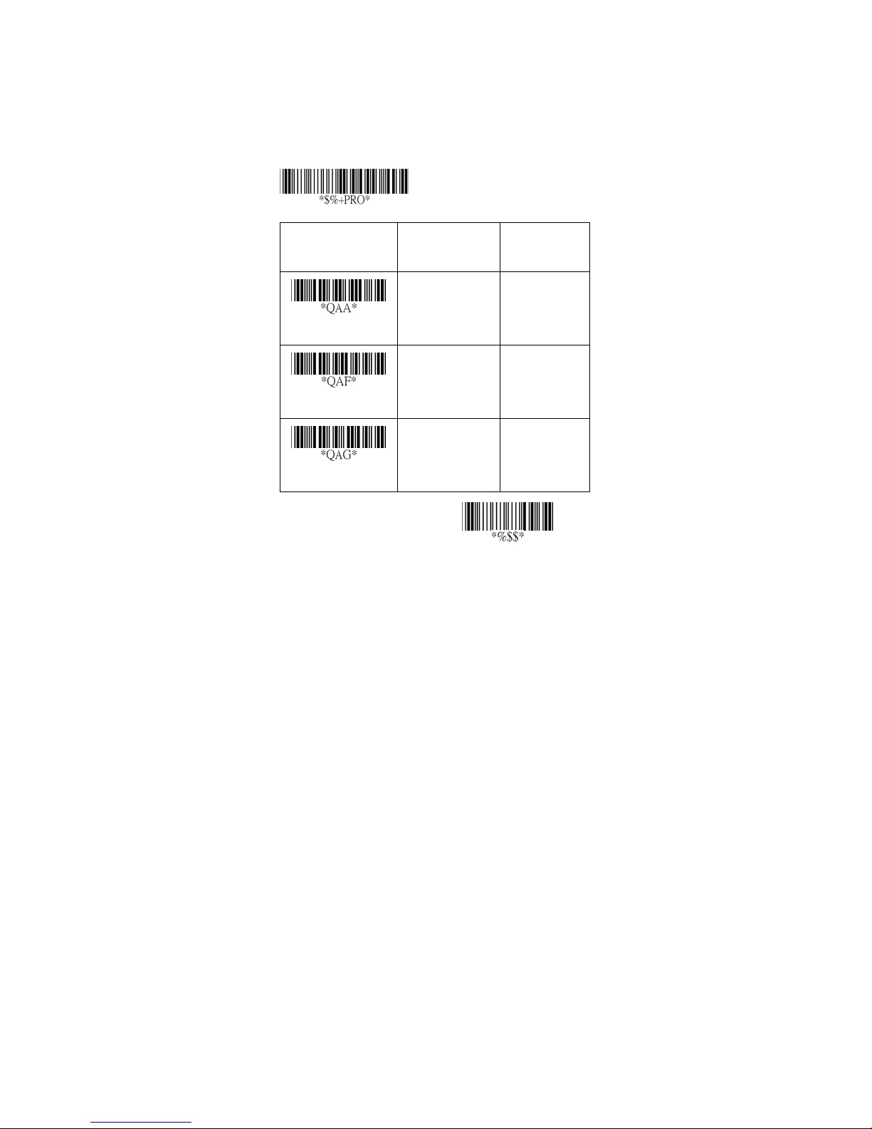
PDF-417
Only the 8250 / 8312 can decode PDF-417.
Truncate leading/ending: Refer to Truncate
leading/ending of UPCA.
Option Bar Code Option Alphanumeric
Program
Entry
Read
Truncate leading
Tru ncate ending
Disable
Enable
0-15 00-15
0-15 00-15
00
01
00
00
*
*
*
Exit
93
Page 100
PDF-417
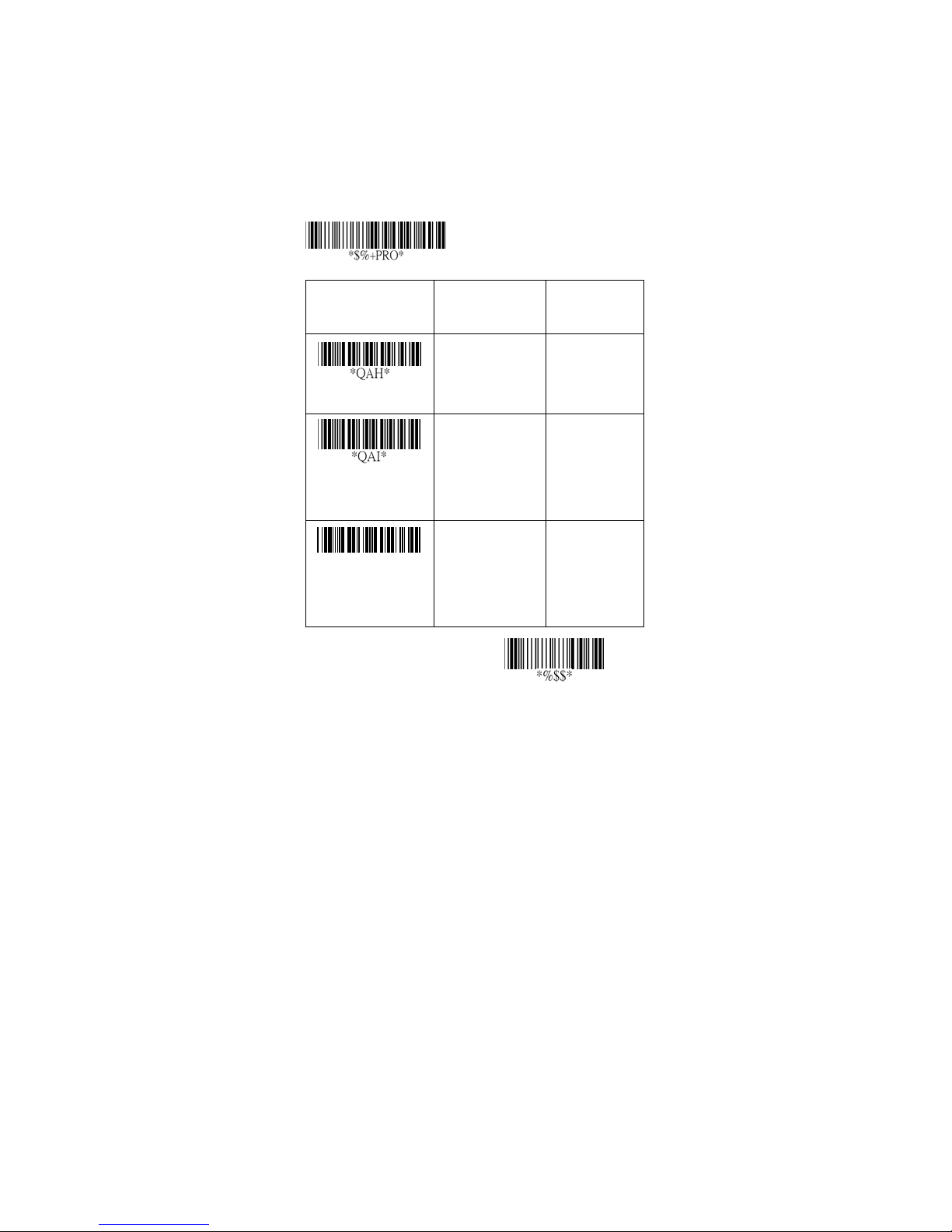
Only the 8250 / 8312 can decode PDF-417.
Code Id setting: Refer to Code ID setting of UPCA.
Insertion group selection: Refer to Insertion group
selection of UPCA.
Option Bar Code Option Alphanumeric
Program
Entry
Code ID setting
Insert group
selection
*QAJ*
Escape sequence
transmit
00-ffH ASCII
code
00-44 00-44
Disable
Enable
00-ffH
< >
*
00
*
00
*
01
94
Exit
 Loading...