

Page 1
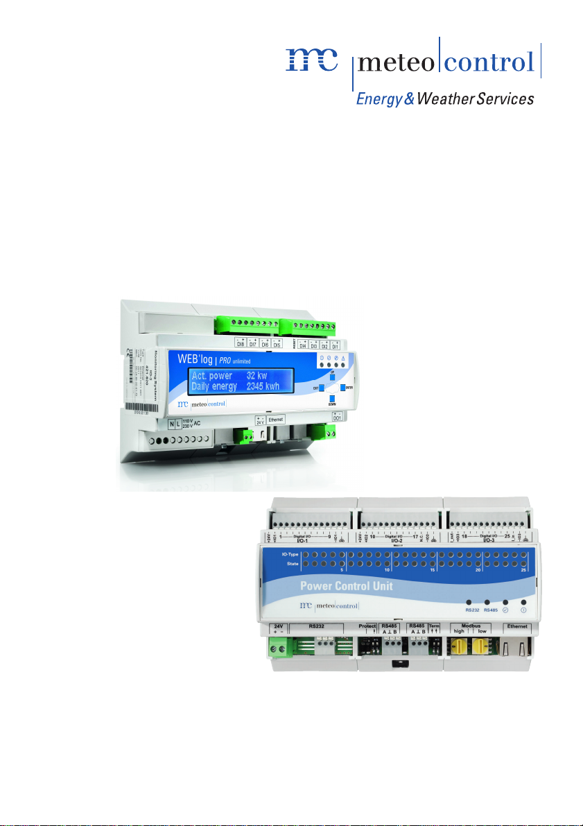
Operating manual
meteocontrol Power Control
Version 03082012
Page 2

Spicherer Str. 48
D-86157 Augsburg
Tel.: +49 (0) 821 / 3 46 66-0
Web: www.meteocontrol.de
Technical support:
Tel.: +49 (0) 821 / 3 46 66-88
Fax: +49 (0) 821 / 3 46 66-11
E-mail: [email protected]
© 2012 meteocontrol GmbH
All rights reserved.
All information in these operating instructions has been compiled and
checked with the greatest care and diligence. However, the possibility of
errors cannot be entirely excluded. meteocontrol GmbH therefore cannot
accept any liability for errors or any circumstances resulting from errors.
Subject to technical alterations.
2/78 meteocontrol Power Control 03082012 - en
Page 3

Contents
Operating manual ............................................................................................................ 1
meteocontrol Power Control ............................................................................................ 1
1.
Use .................................................................................................................... 6
1.1 Introduction ....................................................................................................... 6
1.2 About this operating manual ............................................................................. 6
1.3 Disclaimer ......................................................................................................... 6
2.
Safety ................................................................................................................ 8
2.1 Meaning of the notices ...................................................................................... 8
2.1.1
Further notices ......................................................................................... 8
2.2 Product safety ................................................................................................... 9
2.2.1
Safety instructions for operation .............................................................. 9
2.2.2
Transportation and storage ................................................................... 10
3.
Technical requirements ................................................................................... 11
3.1 EEG (German Renewable Energy Law) ......................................................... 11
3.2 meteocontrol Power Control requirements ...................................................... 11
4.
Functionality .................................................................................................... 12
4.1 meteocontrol Power Control Industrial ............................................................ 12
4.2 Functional display Power Control with WEB`log PRO and PCU ..................... 13
4.3 Functional display Power Control with WEB`log PRO..................................... 14
4.4 Functions ........................................................................................................ 15
4.4.1
Power control......................................................................................... 15
4.4.2
Master functions .................................................................................... 15
4.4.3
Power requirements change message .................................................. 15
4.4.4
Deactivation of the alert ......................................................................... 15
4.4.5
Calculation of the residual energy balance ............................................ 16
4.4.6
Reporting function ................................................................................. 16
5.
Power Control status WEB`log display ............................................................ 17
5.1 Menu entries in the device display .................................................................. 17
6.
Power Control config WEB`log browser .......................................................... 18
6.1 Selection of Modbus device profiles ................................................................ 18
6.2 Assignment of Modbus device profiles ............................................................ 20
6.3 Details on the PCU interface configuration ..................................................... 21
6.3.1
PCU IP configuration ............................................................................. 21
6.3.2
PCU serial configuration ........................................................................ 21
meteocontrol Power Control 03082012 - en 3/78
Page 4

6.3.3
6.4 Details on the PCU device configuration ........................................................ 22
6.5 Power Control online values ........................................................................... 26
6.6 Power requirements configuration .................................................................. 27
7.
7.1 Active power procedures ................................................................................ 34
7.1.1
7.1.2
7.1.3
7.2 Reactive power procedures ............................................................................ 39
7.2.1
7.2.2
7.2.3
7.2.4
7.2.5
7.2.6
7.2.7
7.2.8
7.2.9
7.2.10 cos φ(U) ................................................................................................ 55
7.3 Details fallback operation ................................................................................ 56
8.
9.
9.1 Querying Power Control status ....................................................................... 59
9.2 Power Control power procedures ................................................................... 59
9.2.1
9.2.2
9.2.3
9.2.4
9.3 Power Control system control circuit GCP control .......................................... 60
9.4 Enabling Power Control .................................................................................. 60
9.5 Performing test run (optional) ......................................................................... 60
9.6 Power Control slave WEB`log ........................................................................ 61
10.
10.1
Assignment of the PCU in WEB`log ...................................................... 21
Active and reactive power procedures ............................................................ 32
P(DI) ...................................................................................................... 34
P(AI) ...................................................................................................... 36
P(DI) internal ......................................................................................... 37
cos φ(DI) ............................................................................................... 39
cos φ(AI) ............................................................................................... 41
Control procedure cos φ Fix .................................................................. 44
Q(DI) ..................................................................................................... 45
Power procedures P(DI) and Q(DI) combined ....................................... 47
Q(AI) ..................................................................................................... 49
Q fix ....................................................................................................... 52
Q(U) ...................................................................................................... 52
cos φ(P) ................................................................................................ 53
System control circuit ...................................................................................... 57
Application cases ............................................................................................ 59
Electric installation PCU to WEB`log ..................................................... 59
Installation PCU to WEB`log ................................................................. 59
Configuring PCU ................................................................................... 59
Configuring Power Control .................................................................... 60
The WEB`log .................................................................................................. 62
Connection options .................................................................................... 62
4/78 meteocontrol Power Control 03082012 - en
Page 5

10.1.1
10.1.2 WEB`log Pro master - slave .................................................................. 63
11.
11.1
11.1.1 Description of the elements ................................................................... 65
11.2
11.2.1 Write protect slide switch ....................................................................... 68
11.2.2 Modbus address coding switch.............................................................. 68
11.2.3 Modbus bus termination switch ............................................................. 68
11.3
11.3.1 Safety instructions for installation .......................................................... 68
11.3.2 Mounting ................................................................................................ 70
11.3.3 Connection options ................................................................................ 72
12.
13.
14.
15.
Ripple control receiver with WEB`log, digital inputs ............................... 62
The Power Control Unit (PCU) ........................................................................ 64
PCU Connections ....................................................................................... 64
PCU operating elements ............................................................................ 68
Installation .................................................................................................. 68
The plant control circuit/GCP control............................................................... 76
Power procedures overview ............................................................................ 76
GlossaryTOA .................................................................................................. 77
List of figures ................................................................................................... 77
meteocontrol Power Control 03082012 - en 5/78
Page 6

1. Use
1.1 Introduction
This operating manual describes the meteocontrol Power Control function in
connection with the WEB`log data logger, the power control unit (PCU) and
further components for power control.
The full operating manual can be downloaded in electronic form from
meteocontrol’s website.
The meteocontrol Power Control is broken down into three areas:
Homeline, Industrial and Special Solutions
The focus of this documentation is meteocontrol Power Control Industrial for
industrial solutions
Information on Homeline or Special Solutions can be obtained via the
meteocontrol website or the respective sales contacts.
1.2 About this operating manual
This operating manual is intended for plant planners and installers and forms
the basis for a safe operation of meteocontrol Power Control. The personnel
responsible for installation, operation and maintenance must have read and
understood this operating manual
The operating manual must be accessible at all times.
The term WEB`log Pro is used in representation of the WEB`log Pro and
WEB`log Pro Unlimited device types in this manual.
meteocontrol GmbH accepts no liability for personal injury, damage to
property, or malfunctions and their consequences, insofar as these result
from non-observance of this operating manual.
1.3 Disclaimer
meteocontrol rejects any liability for damage arising from the non-observance
of the operating manual.
This applies, in particular, for damage from:
• Unintended use
• Faulty operation
• Wrongly chosen materials and tools
• Faulty or non-executed maintenance and repairs
6/78 meteocontrol Power Control 03082012 - en
Page 7

With Power Control, meteocontrol shall not be liable for events or
occurrences that are outside its area of influence, such as for the correctness
of the control commands of an energy supplier, non-carrying out of
forwarded control commands, hardware and/or software failures with the
system operator, switching events at the end customer. Any liability for
damage caused by such events and occurrences, such as lost profits, grid
instability, damage to parts of the customer's system, for instance of an
inverter, shall remain expressly excluded.
meteocontrol Power Control 03082012 - en 7/78
Page 8
2. Safety
2.1 Meaning of the notices
Safety notices are classified by a signal word and corresponding colour. The
different safety notices stated below are explained as follows:
Type
2.1.1 Further notices
Warning
Type
Consequences
– Indicates a possibly dangerous situation. Death
in the event of electric shock or severe injury with irreversible damage
may be the result.
Notice
Consequences
– Indicates a possibly damaging situation. Material damage to the
system and its immediate environment may be the result.
A general notice is a piece of information for better understanding and may
include the following:
• Background information
• Special circumstance
• Further or additional information
8/78 meteocontrol Power Control 03082012 - en
Page 9

Information about this topic:
Operating manual Refers to another manual
WEB`log WEB`log PRO operating manual
Web portal Documentation Web portal
Inverter Documents on the inverter
2.2 Product safety
Power Control is a system for controlling and steering different operating
parameters of PV systems (such as reactive and active power).
The connections of the data loggers and modules used here may be loaded
with the permissible signals and signal strengths only.
Installation is only permitted indoors. For installation outdoors or in a dusty
environment, the device must be installed in a standardised protective
enclosure.
2.2.1 Safety instructions for operation
The following must be observed when the data logger is in operation:
• Do not remove the memory card (compact flash) or SIM card.
• Do not open the device.
• Do not make any modifications to the device.
• Immediately take damaged devices out of operation and have them
checked by a qualified electrician.
• Observe local provisions when using the device.
• The safety of the device and the operator cannot be guaranteed if the
device is operated in contravention of the described safety instructions
meteocontrol Power Control 03082012 - en 9/78
Page 10

2.2.2 Transportation and storage
Inspect the device for transport damage on delivery. Notify the transport
company in the event of visible damage.
A damaged device must not be put into operation!
Transport the device in original packaging only. Protect the device from dust
and moisture.
Further information about this topic:
Operating manual end customer Technical data
10/78 meteocontrol Power Control 03082012 - en
Page 11

3. Technical requirements
3.1 EEG (German Renewable Energy Law)
The necessity of active participation of operators of PV systems in the grid
safety management increases with the rising share in the overall power
production. This requires an option to reduce the feed-in power and
participation in the compensation of the reactive power in the grid.
As such, the plant operators must fulfil the following requirements:
• They must be able to reduce the feed-in capacities of plants by remote
control or disconnect plants from the grid entirely.
• They must be able to reduce the reactive power in the grid by reactive
power compensation.
3.2 meteocontrol Power Control requirements
It is recommended to clarify the following requirements of the energy
supplier, inverter manufacturer and plant operator for the Power Control
already in the phase of plant planning:
• Power procedures according to which the requirements of the energy
supplier are implemented in control values for the inverters.
• Power procedures that are supported by WEB`log PRO for the inverter
types used (inverter drivers).
• Characteristic requirements for the power procedure made by the system
operator:
Note: If difficulties regarding the requirement areas arise or
necessary configuration options are not available, consult
your sales contact at meteocontrol.
meteocontrol Power Control 03082012 - en 11/78
Page 12

4. Functionality
4.1 meteocontrol Power Control Industrial
Basic function:
• The requirements for power reduction and control are received from the
energy supplier via a selected interface (digital, analogue, IEC 60870-5-
101) by PCU or WEB`log PRO inputs.
• The control values are determined from the requirements in accordance
with configurable rules. The rules can be defined in accordance with the
requirements. Feedback to the operator is derived optionally.
• The control values are set on the inverter within a response time required
by the energy supplier.
• The energy supplier receives a message about the control value set on
the inverters.
12/78 meteocontrol Power Control 03082012 - en
Page 13
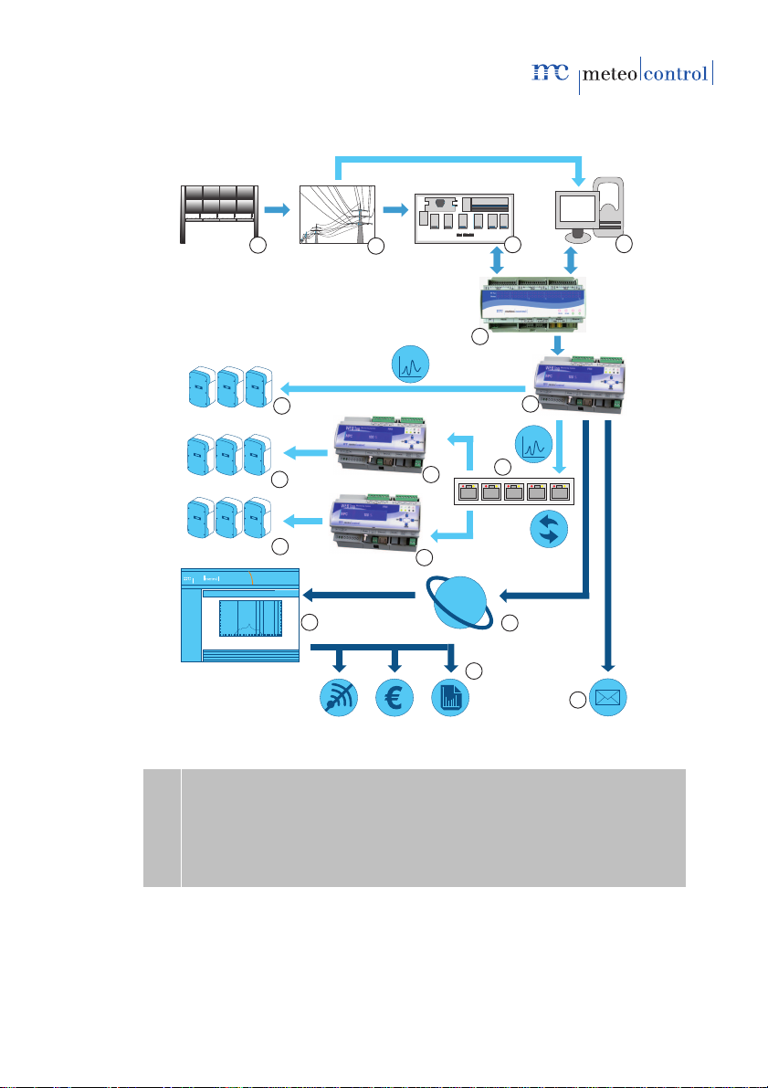
4.2 Functional display Power Control with WEB`log PRO and
safer Sun
P/Q
P/Q
1
2
3
12
10
11
6
5
4
7
8
9
9
8
13
9
PCU
Fig. 1: Functionality PCU<>Power Control
(1) Energy supplier (8) WEB`log PRO as slave
(2) Public grid (9) Inverter
(3) Ripple control receiver (10) Internet
(4) Central computer (11) Web portal
(5) Power control unit (PCU) (12) Power requirements report
(6) WEB`log PRO as master (13) Alert, residual energy balance report
(7) Ethernet switch
meteocontrol Power Control 03082012 - en 13/78
Page 14

safer Sun
P
P
1
2
3
10
11
6
5
4
7
9
8
7
6
7
4.3 Functional display Power Control with WEB`log PRO
Fig. 2: Functionality Power Control
(1) Energy supplier (7) Inverter
(2) Public grid (8) Internet
(3) Ripple control receiver (9) Web portal
(4) WEB`log master (10) Power requirements report
(5) Ethernet switch (11) Alert, residual energy balance
(6) WEB`log slave Report
14/78 meteocontrol Power Control 03082012 - en
Page 15

4.4 Functions
P
P/Q
4.4.1 Power control
Active power procedure (P procedure)
With the internal inputs of the WEB`log PRO only the active
4.4.2 Master functions
4.4.3 Power requirements change message
power procedure can be carried out via digital requirements,
Active and reactive power procedures (P/Q/cos φ procedures)
With the PCU different active and reactive power procedures
can be selected and configured.
In larger plants with several WEB`log PRO devices, a WEB`log
PRO assumes the master function.
The master receives the requirement values from the energy
supplier. The information is forwarded to all WEB`log PRO
devices (slaves) or the configured IP addresses via Ethernet
using a broadcast.
When changing the power requirements, the WEB`log PRO
informs one or more recipients via the reporting route
configured.
The message contains information on the time of changing and
the required power level.
4.4.4 Deactivation of the alert
(portal function, in preparation)
In the event of an enforced reduction, certain alerts are
deactivated for the duration of the reduction (e.g. comparison
energy to irradiance).
The SaferSun internet portal identifies the required reduction
and deactivates the alerts for this period.
meteocontrol Power Control 03082012 - en 15/78
Page 16

4.4.5 Calculation of the residual energy balance
(portal function, in preparation)
Provides an overview of the energy not fed in.
The residual energy balance is calculated from the energy
quantity of the daily simulation and the energy actually fed in
on this day and saved and displayed in the internet portal.
4.4.6 Reporting function
(portal function, in preparation)
Reports can be created, which provide detailed information in
the event of a reduction.
16/78 meteocontrol Power Control 03082012 - en
Page 17

5. Power Control status WEB`log display
The status of the Power Control can be queried and modified via the device
display. The configuration is possible via the browser only.
Fig. 3: Power Control settings
Note: The PC settings are available via the installer login only.
Default 0010
5.1 Menu entries in the device display
PC status
• Active: Power Control is active
• Inactive: Power Control is inactive
meteocontrol Power Control 03082012 - en 17/78
Page 18
6. Power Control config WEB`log
browser
Administrator rights are required to configure the meteocontrol Power Control
in WEB`log.
Login procedure for configuration websites
1. Select the "Profi page" in the start centre.
2. Select the "General" menu item.
3. Select "Login".
4. Enter the administrator password and click "Login"
(default: ist02)
The WEB`log page for device configuration is displayed in the web
browser,
6.1 Selection of Modbus device profiles
Both the power control unit (PCU) and the power quality analyser (PQA) are
connected to the WEB`log via the Modbus protocol.
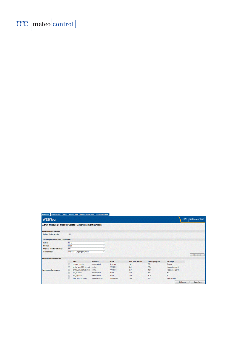
To this end, the required device types from the list of available devices must
be selected and saved.
Under the "Admin Measurement" menu item, "General configuration" item,
the required Modbus settings and Modbus device types are selected.
Fig. 4: Selection of the Modbus settings and Modbus device types
18/78 meteocontrol Power Control 03082012 - en
Page 19
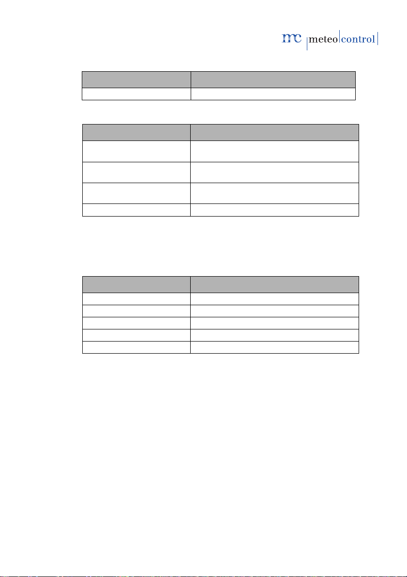
General information
Input field Meaning
Modbus driver version Current driver software version
Serial interface settings
Input field Meaning
Modbus Modbus protocol used, ASCII or RTU,
standard: RTU
Baud rate Baud rate of the serial interface
Standard: 9600 Baud
Data bits \ Parity \ Stop bits Definition of the serial protocol
Standard: 8/N/1
Scan for Modbus message used for scanning
Read new device types
The interface used is assigned via the suffix in the file name of the PCU
device type:
Input field Meaning
pcu_rtu.mod PCU Modbus via RTU (standard)
pcu_tcp.mod PCU Modbus via TCP
janitza_umg604_rtu.mod NAG Modbus via RTU (standard)
janitza_umg604_tcp.mod NAG Modbus via TCP
Save Saves the settings made
Note: Modbus TCP requires no configuration of the interfaces.
meteocontrol Power Control 03082012 - en 19/78
Page 20

6.2 Assignment of Modbus device profiles
Under "Admin Measurement" menu item, "Device configuration" item the
Modbus device type is assigned for the corresponding Modbus client ID.
Fig. 5: Assignment Modbus client ID to the device type
Add serial device
Input field Meaning
Address Client ID of the Modbus device.
Device type Device type of the Modbus device
Scan for serial devices
Input field Meaning
Address space scan Number of client IDs to be scanned (standard:
Scan After a successful scan, the devices found are
1-20). Scan duration depending on the size of
the address range up to one minute.
listed under „Device configuration“
Add TCP/IP device
Input field Meaning
IP address Input of the IP address
20/78 meteocontrol Power Control 03082012 - en
Page 21
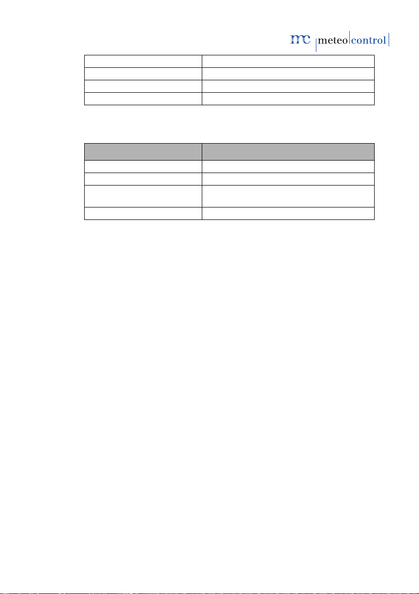
Port Input of the IP port
Client ID Displays the client ID assigned
Device type Assignment of the device type
Add Save the assignments
Device configuration
Input field Meaning
Address Displays the address assigned
Client ID Displays the client ID assigned
Device type Displays the device type assigned, version
and interface
Save Saves the current settings
6.3 Details on the PCU interface configuration
6.3.1 PCU IP configuration
If the PCU is connected to the WEB`log via TCP, depending on the
architecture of the PV system IP network the IP settings of the PCU need to
be changed (IP address, subnet mask).
The meteocontrol device manager service program is required for
configuration. The program can be downloaded from the meteocontrol
download area.
6.3.2 PCU serial configuration
If the PCU is connected to the WEB`log serially via the Modbus RTU, the
Modbus client ID on the device or on the PCU may have to be changed.
Every Modbus client ID may be assigned only once.
This depends on the architecture of the PV system IP network (Modbus
structure and client IDs assigned).
By default, the PCU is serially (Modbus RTU) connected to the WEB`log.
(see section 11.3.3.4 Connection PCU with WEB`log PRO, Modbus RTU).
Note: If the PCU is used with other additional Modbus devices, the
serial bus must be operated with the standard parameters.
6.3.3 Assignment of the PCU in WEB`log
The PCU Modbus client ID is assigned to the PCU device types (see section
6.2).
meteocontrol Power Control 03082012 - en 21/78
Page 22

The client ID is established by scanning for serially connected devices or
entered manually.
Note: WEB'log Pro and PCU are now interconnected.
6.4 Details on the PCU device configuration
The general information in the PCU device configuration are called up via the
"Admin Measurement" menu item in the Power control menu and display the
following parameters:
General information
Fig. 6: General information device configuration
Description Meaning
Write protection Displays the stratus of the write protection
slide switch in the PCU
Communication status Displays the connection
Analogue inputs and outputs
Fig. 7: Configuration of analogue inputs/outputs
22/78 meteocontrol Power Control 03082012 - en
Page 23

Input field Meaning
Analogy input status Display of current input current or error status
Sensor interruption with
less than
Overcurrent with more than Upper threshold of the input current for the
Analogue output status Display of current output current and status
Save Saves the settings made
When falling below the sensor break threshold,
a sensor fault is reported. When exceeding the
overcurrent threshold, a sensor fault is
reported.
Lower threshold of the input current for the
identification of a sensor break. Pre-setting
3.75 mA
identification of overcurrent. Pre-setting 20.25
mA
meteocontrol Power Control 03082012 - en 23/78
Page 24
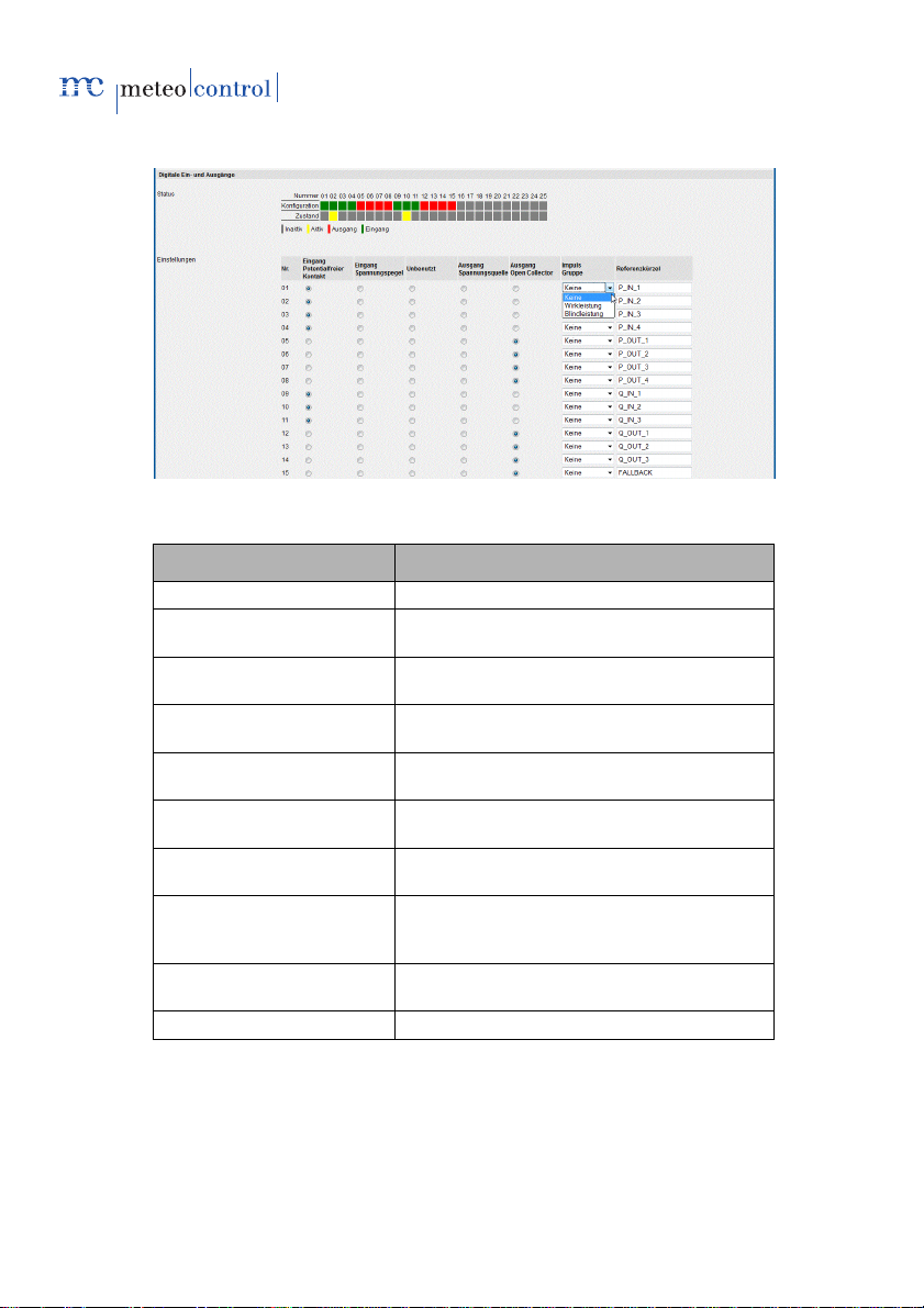
Digital inputs and outputs
Fig. 8:Configuration of digital inputs and outputs
Input field Meaning
Number Number of the inputs/outputs
Status:configuration Configuration of the inputs/outputs
Status:status Status of the inputs/outputs
Eingang Schalter (Switch
input)
Eingang Treiber (Driver
input)
Ausgang Schalter (Switch
output)
Ausgang Treiber (Driver
output)
Impuls Gruppe (Pulse
group)
Reference abbreviation Rule definition: Pre-set value for the control
Save Saves the settings made
The status in the example shows the active/reactive power requirements on
DIO2 and DIO10 without feedback.
(green=input, red=output)
(yellow=input/output is set)
-IOx is created on DI
+IOx is created on DI
DO is switched to -IOx
DO is switched to +IOx
None: static input signal
Active power: dynamic input
Reactive power: dynamic input
value
24/78 meteocontrol Power Control 03082012 - en
Page 25

The last pulse received is rated as the requirement for the relevant pulse
group. On receipt of a new pulse, the previous requirement is reset and the
new requirement applies.
Note: Select the type of the inputs/outputs in accordance with the
wiring. Electric data on the input/output are saved in the PCU
data sheet.
Selection GCP source
As a rule, it is possible to choose between various devices for recording
parameters (i.e. voltage, power, power factor) at the grid connection point
(GCP).
Power quality analyser (PQA) and main computer are currently supported as
the source. The PQA is connected to the WEB`log directly.
Requirements of main computers are received via the RS232 connection of
the PCU.
Fig. 9: Configuration selection power quality analyser
By selecting the power quality analyser, the configuration becomes
complete.
Note: The PQA Modbus client ID is assigned to the PQA device
types (see section 6.2). The client ID is established by
scanning for serially connected devices or entered manually.
Fig. 10: Configuration selection main computer interface IEC 60870-5-101
Note: The parameters for the IEC 60870-5-101 configuration must
be coordinated with the main computer.
meteocontrol Power Control 03082012 - en 25/78
Page 26

Input field Meaning
Baud rate Settings for the serial interface, standard
Length of link address Message settings IEC
Origin address Message settings IEC
Length of station address Message settings IEC
Length of object address Message settings IEC
Link address Message settings IEC
Station address Message settings IEC
Information objects Message settings IEC
Save Saves the settings made
9000 baud
PCU Firmware update
The loading of a new firmware can be carried out by meteocontrol support
only.
Fig. 11: Update PCU Firmware
Input field Meaning
Update firmware Starts the Firmware update
6.5 Power Control online values
The Power Control online values are retrieved via the "Online Values" menu
item. Power Control online values display the current status of the
parameters displayed below.
26/78 meteocontrol Power Control 03082012 - en
Page 27
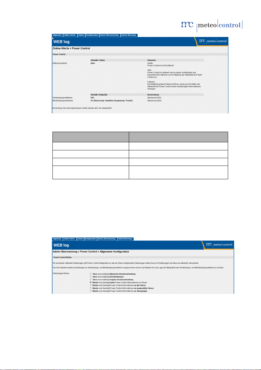
Fig. 12: Power Control online values
Description Meaning
Operating status Active
Active power process Displays the current procedure: P(DI)
Reactive power process Displays the current procedure: cosφ(DI)
Current control value Control value requirement for active and
reactive power procedures in per cent
Note: The highlighted values are updated every 10 seconds. It is
not possible to configure the online values.
6.6 Power requirements configuration
The configuration of the Power Control is retrieved via the "Admin
Monitoring" menu item and displays the selection of the procedures for
control value distribution.
Fig. 13: WEB`log master without slaves
meteocontrol Power Control 03082012 - en 27/78
Page 28

Fig. 14: WEB`log master with broadcast to all slaves
Fig. 15: WEB`log master with selected slaves
Fig. 16: WEB`log master with slave groups
Input field Meaning
Slave (allgemeiner Broadcast)
[Slave (general broadcast)]
Slave (Einzelmeldungen)
[Slave (single messages)]
Slave (Gruppen-Broadcast)
[Slave (group broadcast)]
Master (keine Slaves) [Master Transfers no control value information to
28/78 meteocontrol Power Control 03082012 - en
Receives control value information from
the master about the general broadcast
Receives control value information from
the master about single message
Receives control value information from
the master about group broadcast
Page 29

(no slaves)] slaves
Master (alle Slaves) [Master
(all slaves)]
Master (ausgewählte Slaves)
[Master (selected slaves)]
Master (Slavegruppen)
[Master (slave groups)]
Slave group Slave group ID for addressing
IP address Input and activation for up to 20 slave
Active Activates the address field
Transfers control value information as a
broadcast to all slaves available
Transfers control value information to all
slaves selected that are activated in the
address list
Transfers control value information as a
broadcast to all slave groups
WEB`logs
Note: The data logger activated as the master sends information
on active and reactive power values to slaves. Active and
reactive power procedures can be set and configured on the
master only.
WEB`log Pro definition as a slave
If the WEB`log is operated as a slave, control values must be defined that
are used in the event of a communication failure master->slave WEB`log.
Fig. 17: Definition WEB`log slave general broadcast
meteocontrol Power Control 03082012 - en 29/78
Page 30

Fig. 18: Definition WEB`log slave single message
Fig. 19: Definition WEB`log slave group broadcast
Input field Meaning
Active power Size of the active power in the event of a
communication loss in %
Reactive power Size and type of the reactive power in the
event of a communication loss in %
Displacement factor Size and type of the displacement factor in
the event of a communication loss
Parameter used Reactive power parameter used in the
event of a communication loss
Slavegruppe (Slave group) Slave group ID for addressing
30/78 meteocontrol Power Control 03082012 - en
Page 31

Control process
The active and reactive power procedures selected determine the processing
type of the requirements received. Details on the configuration of the
procedures are stated in section 7 Active and reactive power procedures.
The plant control circuit ensures the observance of the values required on
the GCP. Details on the configuration of the control circuit are stated in
section 8 System control circuit.
Power Control System Data
Fig. 20: Power control system data
Input field Meaning
Agreed connection power PAV Maximum feed-in active power on the
Agreed maximum apparent
power S
Nominal voltage AC U
Amax
Nominal voltage at the grid connection
Nom
grid connection point agreed with the
energy supplier
Maximum apparent power on the grid
connection point agreed with the energy
supplier
point
Enabling Power Control
It is recommended to only enable the Power Control when the configuration
has been completed.
Fig. 21: Enabling Power Control
Input field Meaning
Power Control Enables or disables the PC
Save Saves the settings
meteocontrol Power Control 03082012 - en 31/78
Page 32

7. Active and reactive power procedures
The procedures are set via Admin measurement > Power Control > General
settings.
The procedures cannot use any requirement sources and can also not be
combined.
• A procedure for active power reduction can be selected without a
procedure for reactive power control being selected. (Selecting the
procedure for reactive power control is optional).
• A procedure for reactive power control can only be selected if a
procedure for active power reduction was selected (selecting the
procedure for active power reduction is required).
• An input screen for setting the procedures is displayed for the procedures
selected.
32/78 meteocontrol Power Control 03082012 - en
Page 33

List of active power procedures
Fig. 22: Active power procedure selection
List of reactive power procedures
Fig. 23: Reactive power procedure selection
Normal operation
In normal operation,
• control values are determined and sent to the inverters,
• changes to the requirements are logged and
• a notification is sent when changing the active power reduction (if
notification is configured) from the requirements in accordance with the
defined rules.
Fallback operation
If no requirements are received from the master WEB`log or if no control
values can be assigned, fallback operation starts.
Possible causes:
• Error in the receipt of the requirements (digital in, analogue in or
IEC).
• Error in the definition of the configuration for the power procedures
chosen.
• Communication error between PCU and WEB`log master
meteocontrol Power Control 03082012 - en 33/78
Page 34

7.1 Active power procedures
7.1.1 P(DI)
With this procedure, the active power P is used as the control value.
The DI requirement is provided by the energy supplier as a digital input
signal, e.g. digital ripple control receiver and connected to the digital inputs of
the PCU.
Note: Only individual outputs of the ripple control receiver may be
assigned. Bit samples (DI 1,2,4 = H‘07 for assignment of
requirement value) are not permitted.
Feedback is provided via the digital outputs of the PCU.
Fig. 24: Active power procedure control P(DI)
Note: The areas highlighted in red in the Fig. shown below
illustrate the settings fields relevant for the active power
procedure P(DI).
Input field Meaning
Active power procedure Indicates the active power procedure P(DI)
selected
34/78 meteocontrol Power Control 03082012 - en
Page 35

Control values in the fallback mode
Input field Meaning
Active power Control value for reduction in active power in
Digital output Feedback output
per cent
Active power procedure via digital inputs
Input field Meaning
Number Control number
Active Setting whether the rule should be applied
Input Reference abbreviation of the digital input
Output Feedback output
P% Relative active power in per cent (relating to
Capping the feed-in power
at PAV
active power rule (line)
PAV) and confirmation that the control value is
used for this rule
Limitation of the feed-in power to PAV
meteocontrol Power Control 03082012 - en 35/78
Page 36

7.1.2 P(AI)
With this procedure, the active power P is used as the control value.
The AI requirement is provided by the energy supplier as an analogue input
signal, e.g. analogue ripple control receiver and connected to the analogue
input of the PCU.
With the analogue input of the PCU, the reduction in active power is carried
out via an analogue input signal (4–20mA power signal in accordance with
DIN IEC 60381-1). The feedback is carried out via the analogue output (4–
20mA power signal in accordance with DIN IEC 60381-1) of the PCU. The
power reduction from the analogue value is calculated via a linear equation.
For the configuration, the value pairs P1 and P2 are required, which are at
the end of the line (min and max).
Fig. 25: Active power procedure control P(AI)
Note: The areas highlighted in red in the Fig. shown here illustrate
Input field Meaning
Active power procedure Indicates the active power procedure P(AI)
the settings fields relevant for the active power procedure
P(AI). A simultaneous use of the analogue input for active
and reactive power procedures is not possible.
selected
Control values in the fallback mode
Input field Meaning
Active power Control value for active power reduction in per
36/78 meteocontrol Power Control 03082012 - en
cent
Page 37

Digital output Feedback output
Active power procedure via analogue input
Input field Meaning
The lowest measured value Value pair for the definition of the lowest
The highest measured value Value pair for the definition of the highest
Sensitivity Sensitivity setting: indicates from when a
Issue current control value Control value issue setting: indicates whether
Capping the feed-in power
at PAV
7.1.3 P(DI) internal
With this procedure, the active power P is used as the control value.
The DI requirement is provided by the grid operator as a digital input signal,
e.g. digital ripple control receiver and connected to the internal digital inputs
DI of the WEB`log.
working point (example: 4.5 mA corresponds
to zero per cent)
working point (example: 19.5 mA
corresponds to one hundred per cent)
change to the analogue input results in a
change to the control value (indicated in %)
the current input current is fed back on the
analogue current output
Limitation of the feed-in power to PAV
meteocontrol Power Control 03082012 - en 37/78
Page 38

Fig. 26: Active power procedure P(DI) internal
Feedback on the set power level to the energy supplier is not possible with
this procedure.
Contrary to the P(DI) procedure via PCU, use of bitmasks is permitted for the
P(DI) procedure via WEB`log.
Settings
Input field Meaning
Digital inputs column (DI 4 DI 1)
Configuration column Power requirement in per cent when
Capping the feed-in power at
PAV
Configurable for up to 16 different power
levels. Green indicates what input must be
activated
occupying the relevant digital inputs
Limitation of the feed-in power to PAV
38/78 meteocontrol Power Control 03082012 - en
Page 39

7.2 Reactive power procedures
7.2.1 cos φ(DI)
With this procedure, the displacement factor cos φ is used as the control
value. The DI requirement is provided by the grid operator as a digital input
signal, e.g. digital ripple control receiver and connected to the digital inputs of
the PCU.
The assignment is carried out via a parameter table. The breakdown and
assignment of the levels are freely selectable. In doing so, every digital PCU
input corresponds to a requirement value.
Feedback is provided via the digital outputs of the PCU.
Fig. 27: Reactive power procedure cos φ(DI)
Note: The areas highlighted in red in the Fig. shown here illustrate
the settings fields relevant for the reactive power procedure
cos φ(DI).
meteocontrol Power Control 03082012 - en 39/78
Page 40
Input field Meaning
Reactive power procedure Indicates the active reactive power
procedure cos φ (DI) selected
Control values in the fallback mode
Input field Meaning
Displacement factor Control value cos φ
Digital output Feedback output
Reactive power procedure via digital inputs
Input field Meaning
Number Control number
Active Setting whether the rule should be applied
Input Reference abbreviation of the digital input.
Output Reference abbreviation of the feedback
Displacement factor cos φ Control values cos φ for the reactive
A reactive power rule specifies a line
output
power reduction as well as an interface to
confirm that the control value is applied
with this rule
40/78 meteocontrol Power Control 03082012 - en
Page 41

7.2.2 cos φ(AI)
With this procedure, the displacement factor cos φ is used as the control
value. The AI requirement is provided by the grid operator as an analogue
input signal, e.g. analogue ripple control receiver and connected to the
analogue input of the PCU.
The value is provided by the grid operator as an analogue input signal (4 –
20mA).
The displacement factor is calculated from the analogue value via a linear
equation. For the configuration, the value pairs P1 and P2 are required,
which are at the end of the line. Furthermore, the excitation type per point is
required.
Fig. 28: Example curve cosφ(AI)
Note: Feedback can be provided via the analogue output of the
PCU.
A simultaneous use of the analogue input for active/and
reactive power procedures is not possible.
meteocontrol Power Control 03082012 - en 41/78
Page 42

Fig. 29: Reactive power procedure control cos φ(AI)
Note: The areas highlighted in red in the Fig. shown here illustrate
the settings fields relevant for the reactive power procedure
cos φ(AI).
Input field Meaning
Reactive power procedures Indicates the active reactive power
procedure cos φ (AI) selected
Control values in the fallback mode
Input field Meaning
Displacement factor Control value cos φ
Digital output Feedback output
42/78 meteocontrol Power Control 03082012 - en
Page 43

Reactive power procedure via analogue input
Input field Meaning
Lowest measurement value Indicated in mA and %. Value pair for the
definition of the lowest working point
(example: 4.3mA corresponds to factor
0.975 – overexcited)
Highest measurement value Indicated in mA and %. Value pair for the
definition of the highest working point
(example: 19.7mA corresponds to factor
0.995 – underexcited)
Sensitivity Sensitivity setting: indicates from when a
change to the analogue input results in a
change to the control value
Issue current control value Control value issue setting: indicates
whether the current input current is fed back
on the analogue current output
meteocontrol Power Control 03082012 - en 43/78
Page 44
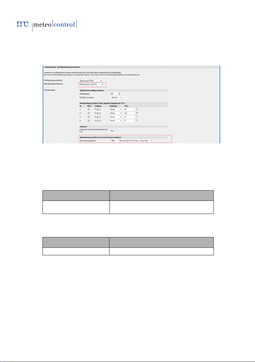
7.2.3 Control procedure cos φ Fix
With this procedure, a fixed displacement factor cos φ is used as the control
value. To this end, a configurable, consistent value is saved. No feedback is
provided.
Fig. 30: Reactive power procedure control cos φ Fix
Note: The areas highlighted in red in the Fig. shown here illustrate
the settings fields relevant for the reactive power procedure
cos φ Fix.
Input field Meaning
Reactive power procedure Indicates the selected reactive power
procedure cos φ Fix
Reactive power procedure 099 with a fixed control value
Input field Meaning
Displacement factor Control value cos φ
44/78 meteocontrol Power Control 03082012 - en
Page 45
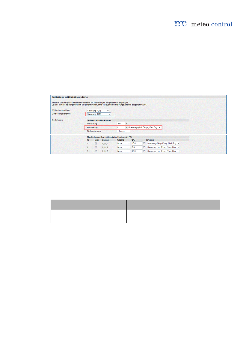
7.2.4 Q(DI)
With this procedure, the reactive power Q is used as the control value.
The DI requirement is provided by the energy supplier as a digital input
signal, e.g. digital ripple control receiver and connected to the digital inputs of
the PCU.
The assignment is carried out via a parameter table. The breakdown and
assignment of the levels are freely selectable. In doing so, every digital PCU
input corresponds to a requirement value.
Feedback is provided via the digital outputs of the PCU.
Fig. 31: Reactive power procedure control Q(DI)
Note: The areas highlighted in red in the Fig. shown here illustrate
Input field Meaning
Reactive power procedures Indicates the reactive power procedure
the settings fields relevant for the reactive power procedure
Q(DI).
Q(DI) selected
meteocontrol Power Control 03082012 - en 45/78
Page 46

Control values in the case of fallback
Input field Meaning
Reactive power Control values for reactive power control
Digital output Feedback output
Reactive power procedure via digital inputs
Input field Meaning
Number Control number
Active Setting whether the rule should be applied
Input Reference abbreviation of the digital input. A
Output Reference abbreviation of the feedback
Q(%) Reactive power control value for reactive
reactive power rule specifies a line
output
power reduction in per cent
46/78 meteocontrol Power Control 03082012 - en
Page 47
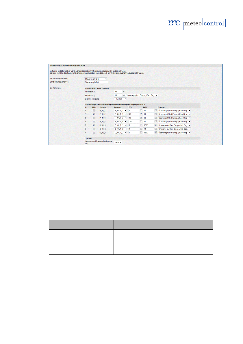
7.2.5 Power procedures P(DI) and Q(DI) combined
The following example indicates the combination of a P(DI) controlled active
power procedure and a Q(DI) controlled reactive power procedure.
Fig. 32: Power procedures P(DI) and Q(DI) combined
Note: The areas highlighted in red in the Fig. shown here illustrate
the settings fields relevant for the active power procedure
P(DI) and the reactive power procedure Q(DI).
Of the DI requirement source is chosen for the active power
and reactive power procedures, the configuration is made in
a table. Ensure that the rule for P and Q are not inadvertently
mixed. The relevant parameter is used if the checkbox is set
to the right next to the corresponding input field.
Input field Meaning
Active power procedures Indicates the active power procedure P(DI)
selected
Reactive power procedures Indicates the reactive power procedure Q(DI)
selected
meteocontrol Power Control 03082012 - en 47/78
Page 48

Control values in the case of fallback
Input field Meaning
Active power Control value for active power control in
Reactive power Control value for reactive power control
Digital output Feedback output
per cent
in per cent
Active and reactive power procedures via digital inputs
Input field Meaning
Number Control number
Active Setting whether the rule should be
Input Reference abbreviation of the digital
Output Reference abbreviation of the feedback
P(%) Active power control value for active
Q(%) Reactive power control value for reactive
applied
input. A reactive power rule specifies a
line
output
power reduction in per cent
power reduction in per cent
48/78 meteocontrol Power Control 03082012 - en
Page 49

7.2.6 Q(AI)
With this procedure, the reactive power Q is used as the control value.
The AI requirement is provided by the energy supplier as an analogue input
signal, e.g. analogue ripple control receiver and connected to the analogue
input of the PCU.
The value is provided by the energy supplier as an analogue input signal
(typically: 4–20mA). The reactive power is calculated from the analogue
value via a linear equation.
The following details are required for the configuration:
• The value pairs P1 and P2, which are at the end of the line (min and
max).
• Details in what areas the points are (overexcited or underexcited)
Fig. 33: Curve Q(AI)
Note: Feedback is provided via the analogue output of the PCU. A
simultaneous use of the analogue input for active/and
reactive power procedures is not possible.
meteocontrol Power Control 03082012 - en 49/78
Page 50

Fig. 34: Reactive power procedure control Q(AI)
Note: The areas highlighted in red in the Fig. shown here illustrate
the settings fields relevant for the reactive power procedure
Q(AI).
Input field Meaning
Reactive power procedure Indicates the reactive power procedure
Q(AI) selected
Control values in the case of fallback
Input field Meaning
Reactive power Control value for reactive power control in
per cent
Excitation Excitation type reactive power
(overexcited/underexcited)
Digital output Feedback output
50/78 meteocontrol Power Control 03082012 - en
Page 51

Reactive power procedure via analogue input
Input field Meaning
The lowest measured value Indicated in mA and %. Value pair for the
definition of the lowest working point
(example: 4mA corresponds to a control
value of 15% - underexcited)
The highest measured value Value pair for the definition of the highest
working point (example: 20mA
corresponds to a control value of 15% overexcited)
Sensitivity Sensitivity setting: indicates from when a
change to the analogue input results in a
change to the control value
Issue current control value Control value issue setting: indicates
whether the current input current is fed
back on the analogue current output
meteocontrol Power Control 03082012 - en 51/78
Page 52

7.2.7 Q fix
With this procedure, a fixed reactive power Q is used as the control value. To
this end, a configurable, consistent value is saved in WEB`log. No feedback
is provided.
Fig. 35: Reactive power procedure control Q Fix
Note: The areas highlighted in red in the Fig. shown here illustrate
Input field Meaning
Reactive power procedure Indicates the selected reactive power
Control values in the fallback mode
Input field Meaning
Digital output Feedback output
the settings fields relevant for the reactive power procedure
Q fixed.
procedure Q Fix
Reactive power procedure with a fixed control value
Input field Meaning
Reactive power Control value Q in %
Excitation Excitation type reactive power
(overexcited/underexcited)
7.2.8 Q(U)
With this procedure, the reactive power Q is used as the control value.
The requirement U is received from the measurement device chosen and is
assigned to the control value with a linear equation.
52/78 meteocontrol Power Control 03082012 - en
Page 53

Power quality analyser and main computer are the currently supported
Hyst
Nom
measurement devices (see section 6.4 Details on the PCU device
configuration -> Selection GCP source).
Fig. 36: Reactive power procedure control Q(U)
Control values in the fallback mode
Input field Meaning
Displacement factor Control value cos φ
Excitation Excitation type reactive power
(overexcited/underexcited)
Digital output Feedback output
Reactive power procedure via voltage requirement U
Input field Meaning
Curve Type of curve
Point 1…4 Support points 1…4
U
Hysteresis as the ratio of U/U
Lower limit cos φ
Lower cos φ limit up to which the curve
Limit
is moved, then the selected cos φ is
used as the fixed value
7.2.9 cos φ(P)
With this procedure, the displacement factor cos φ is used as the control
value. The requirement P is received from the selected measurement device
and is assigned to the control value with a linear equation.
meteocontrol Power Control 03082012 - en 53/78
Page 54
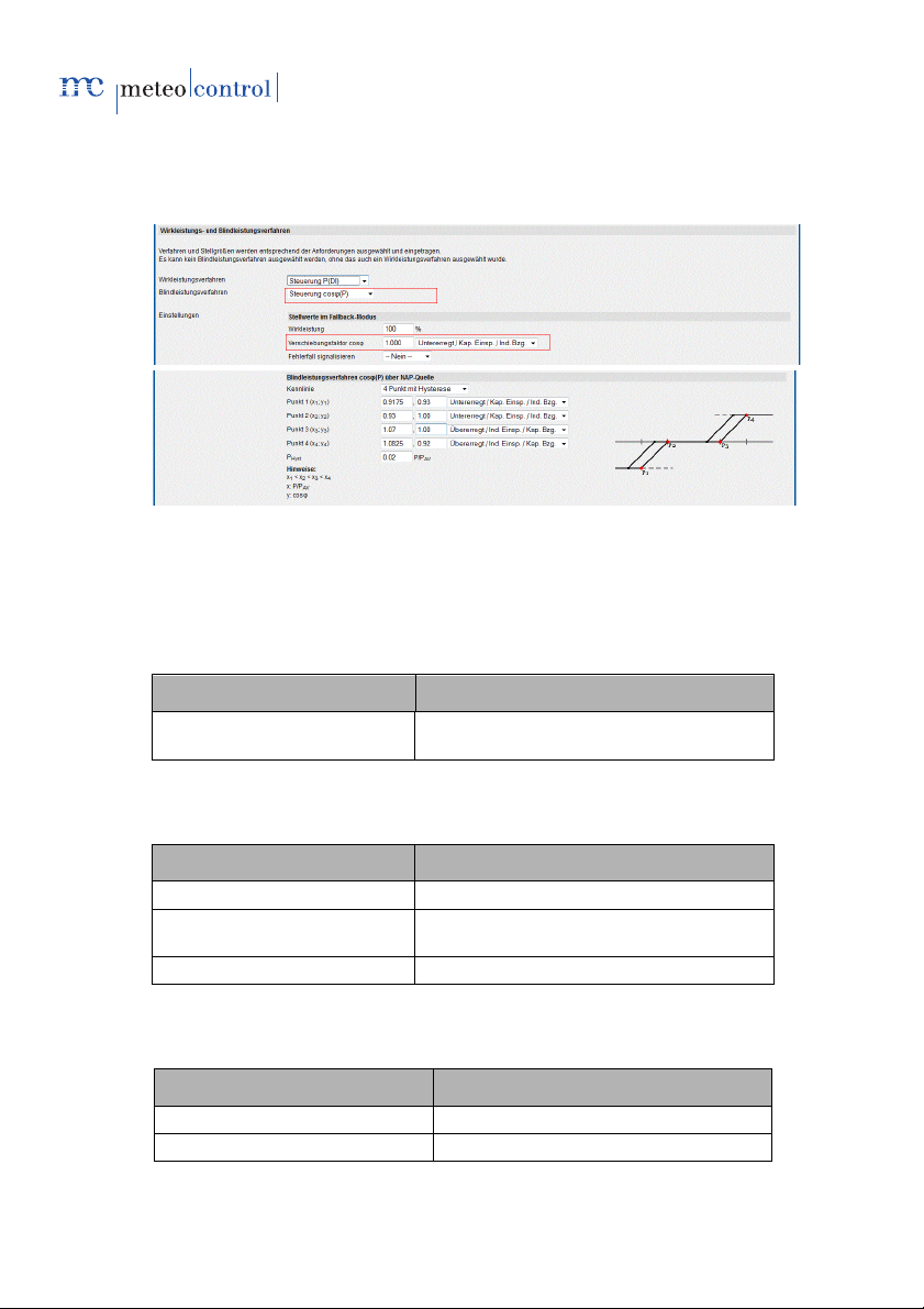
Power quality analyser and main computer are the currently supported
measurement devices (see section 6.4 Details on the PCU device
configuration -> Selection GCP source).
Fig. 37: Reactive power procedure control cosφ(P)
Note: The areas highlighted in red in the Fig. shown here illustrate
the settings fields relevant for the reactive power procedure
cosφ(P).
Input field Meaning
Reactive power procedures Indicates the active reactive power
procedure cos φ (P) selected
Control values in the fallback mode
Input field Meaning
Displacement factor Control value cos φ
Excitation Excitation type reactive power
Digital output Feedback output
(overexcited/underexcited)
Displacement factor procedure via power requirement P
Input field Meaning
Curve Type of curve
Point 1…4 Support points 1…4
54/78 meteocontrol Power Control 03082012 - en
Page 55

P
Hyst
Hysteresis as the ratio of P/PAV
7.2.10 cos φ(U)
With this procedure, the displacement factor cos φ is used as the control
value. The requirement U is received from the measurement device chosen
and is assigned to the control value with a linear equation.
Power quality analyser and main computer are the currently supported
measurement devices (see section 6.4 Details on the PCU device
configuration -> Selection GCP source).
Fig. 38: Reactive power procedure control cos φ(U)
Note: The areas highlighted in red in the Fig. shown here illustrate
Input field Meaning
Reactive power procedures Indicates the active reactive power
the settings fields relevant for the reactive power procedure
cos φ(U).
procedure cos φ (U) selected
Control values in the fallback mode
Input field Meaning
Displacement factor Control factor cos φ
Digital output Feedback output
meteocontrol Power Control 03082012 - en 55/78
Page 56

Hyst
Nom
Displacement factor procedure via voltage requirement U
Input field Meaning
Curve Type of curve
Point 1…4 Support points 1…4
U
Hysteresis as the ratio of U/U
7.3 Details fallback operation
In the event of a communication failure between PCU and WEB`log or
WEB`log master and slave, i.e. if no requirement values are received any
more, fallback operation becomes active after a delay period of 10 minutes
and fallback values are used. During the delay period, the parameter set of
the last valid control values is used.
When activating the Power Control with incomplete requirement information,
fallback operation becomes immediately active.
56/78 meteocontrol Power Control 03082012 - en
Page 57

8. System control circuit
Controlling ensures that the changes to the power data are compensated by
the PV systems on the way to the GCP (NS or MS) and the requested
requirements are implemented on the GCP.
• The GCP controlling procedure is only active if the reactive power
procedure is selected.
For the correct function of the system control circuit, the following parameters
must be entered correctly.
• In the area
Admin monitoring » Power Control » General configuration:
• Agreed connection power PAV [kW]
• Maximum agreed apparent power S
• Nominal voltage AC U
Nom
[kV]
• Parameter model [transformer / no transformer] *
• Transformer nominal power [kVA] *
• Lower P
• Lower cos(ϕ)
• Upper Q
The upper Q
cos(ϕ)
[%]
limit
*
limit
[%] *
limit
field generates its content automatically from the lower
limit
field or vice versa. The input of the data issued by the inverter
limit
manufacturer in one of the two fields is therefore not sufficient. If the
cursor leaves the field or if the enter key is pressed, the relevant other
field is updated.
• In the area
Konfiguration » Anlagendaten (Configuration » System data), the
following data must be entered:
• Installed power [kW] *
Important! All the data must be correct. The data entered, in particular the
parameters highlighted with *, are elementary for the correct control.
Incorrectly entered data, incomplete target value queries or requested target
values outside the technically feasible range of the inverter(s) result in
control malfunctions.
Amax
[kVA]
Fig. 39: GCP control circuit configuration
meteocontrol Power Control 03082012 - en 57/78
Page 58

limit
limit
limit
Input field Meaning
Parameter model Selection of the parameter model to calculate
Transformer nominal power Nominal output of the medium voltage
Lower P
Lower cos φ
Upper Q
Generate start
configuration
Work threshold of the NAP control circuit
Work threshold of the NAP control circuit
the start configuration control circuit
transformer
Work threshold of the NAP control circuit
Generate the start configuration for the GCP
control circuit
Note on the grid connection point (GCP):
In addition to the configuration in the WEB`log, the power quality analyser
must also be configured itself.
It is recommended that the transmitters on the GCP (support type current
transformer, voltage converter) are installed in accordance with the generator
meter arrow system.
When selecting the components, it should be ensured that they have the
precision classes of at least 0.5 (fine measurement device classes).
Furthermore, power and current converter must be selected such that the
measurement range of the power quality analyser is utilised inasmuch
possible. To control the active factor, a one-phase measurement is sufficient,
a three-phase measurement is, however, recommended, as at the medium
voltage end the transformer usually has a triangular switching group, while
the voltage is measured against a star point.
A power quality analyser that suits the transformers accordingly should be
chosen for the measurement, which records the active factor and current
feed-in power at an interval of no more than 5 seconds and transfers this
information to the WEB`log.
Electrical installation GCP
The electrical planning and installation of PV systems, in particular the GCP
part of the PQA, is not included in this manual. The following steps for the
use of the PQA must be observed:
- PQA to GCP
The power quality analyser is connected to the grid connection point in
accordance with the relevant valid directives for low voltage and/or
medium voltage. Depending on the system design, transmitters are
required (support type current transformer, voltage converter).
58/78 meteocontrol Power Control 03082012 - en
Page 59

- PQA to WEB`log
The power quality analyser is connected to the WEB`log via an RS485
connection
9. Application cases
9.1 Querying Power Control status
The current operating mode and the control values of the power procedures
are displayed on the WEB`log website Online values >> Power Control.
Details can be found in section 6.5 Power Control online values.
9.2 Power Control power procedures
The following example shows you the steps for installing Power Control.
Example:
Structure WEB`log with PCU via RTU, power procedures P(DI) and cos
φ(DI):
9.2.1 Electric installation PCU to WEB`log
Connect the PCU with the WEB`log according to section 11.3.3.1 Ripple
control receiver with PCU, digital inputs.
9.2.2 Installation PCU to WEB`log
1. Publish PCU device type in WEB`log PRO according to section 6.1
Selection of Modbus device.
Note: Serial interface already has correct configuration.
2. Import, select and save PCU device type.
3. Assign PCU address to a PCU device type in accordance with section 6.1
Selection of Modbus device profiles.
4. Trigger scan for serial devices (PCU default address: 1).
5. Assign device address in the device type drop-down box to the PCU type.
6. Save settings made.
9.2.3 Configuring PCU
Configure digital inputs/outputs in accordance with the requirements. See
section 6.4 Details on the PCU device configuration.
meteocontrol Power Control 03082012 - en 59/78
Page 60

9.2.4 Configuring Power Control
For a control value to be assigned, at least one active rule must be defined
for every controlling procedure selected.
1. Define data logger as the master
2. Configure communication with slaves:
- do not use any slaves. See section 6.6 Power requirements
configuration Fig. 13
- Broadcast message to all slaves of the system. See section 6.6 Power
requirements configuration Fig. 14
- Define list with slaves. See section 6.6 Power requirements
configuration Fig. 15.
- state slave group. See section 6.6 Power requirements configuration
Fig. 16
3. Select reactive power procedure
Note: If no Q or cos φ rule is required, "-none-" must be selected as
the reactive power procedure.
4. Define parameters for the power procedures in accordance with the
requirements
Active rule is defined.
If no active rule is assigned to the reactive power procedure, the fallback
case applies. See section 7.3 Details fallback operation.
9.3 Power Control system control circuit GCP control
- The power quality analyser is configured as Modbus device type in
WEB`log.
- The transformer nominal output configuration parameter is entered for
the system control circuit
- The start configuration for the control is created
See section 8 System control circuit.
9.4 Enabling Power Control
Do not enable Power Control until all requirements for the Power Control
have been fully defined and configured.
9.5 Performing test run (optional)
If it is ensured that Power Control was implemented in accordance with the
requirements, a test run should be performed in the system.
60/78 meteocontrol Power Control 03082012 - en
Page 61

After performing a successful test run, set the write protection slide switch of
the PCU to ON to prevent abuse or mistaken reconfiguration.
9.6 Power Control slave WEB`log
The slave data logger receives the control values for the Power Control from
the master. The power procedures are defined in the master and the
parameters are sent to the slaves.
1. Define data logger as the slave
2. Configure the type of the message to be received
- General broadcast message
See section 6.6 Power requirements configuration Fig. 17
- Single message
See section 6.6 Power requirements configuration Fig. 18
- Group broadcast
See section 6.6 Power requirements configuration Fig. 19
meteocontrol Power Control 03082012 - en 61/78
Page 62
+ - + -
- +- +- +- +- +- +- +- +
DI1DI1DI1DI1AI1AI2AI3AI4
RESET
Phone Ethernet RS485 RS232
24 V DO1
AC
230 V
110 V
N L
1
6
2345
10. The WEB`log
The WEB`log is the central element for the implementation of the
meteocontrol Power Control.
Power Control function:
• Receipt of the processed requirement values from the PCU
• Receipt of the requirement values from WEB`log digital inputs
• Receipt of measurement values from the grid connection point
• Algorithm system control circuit for power on the grid connection point
• Requirement procedure and determination of control values
• As the master: sending of control values to slaves
• As the slave: receipt of control values
• Transfer of control values to the inverters
10.1 Connection options
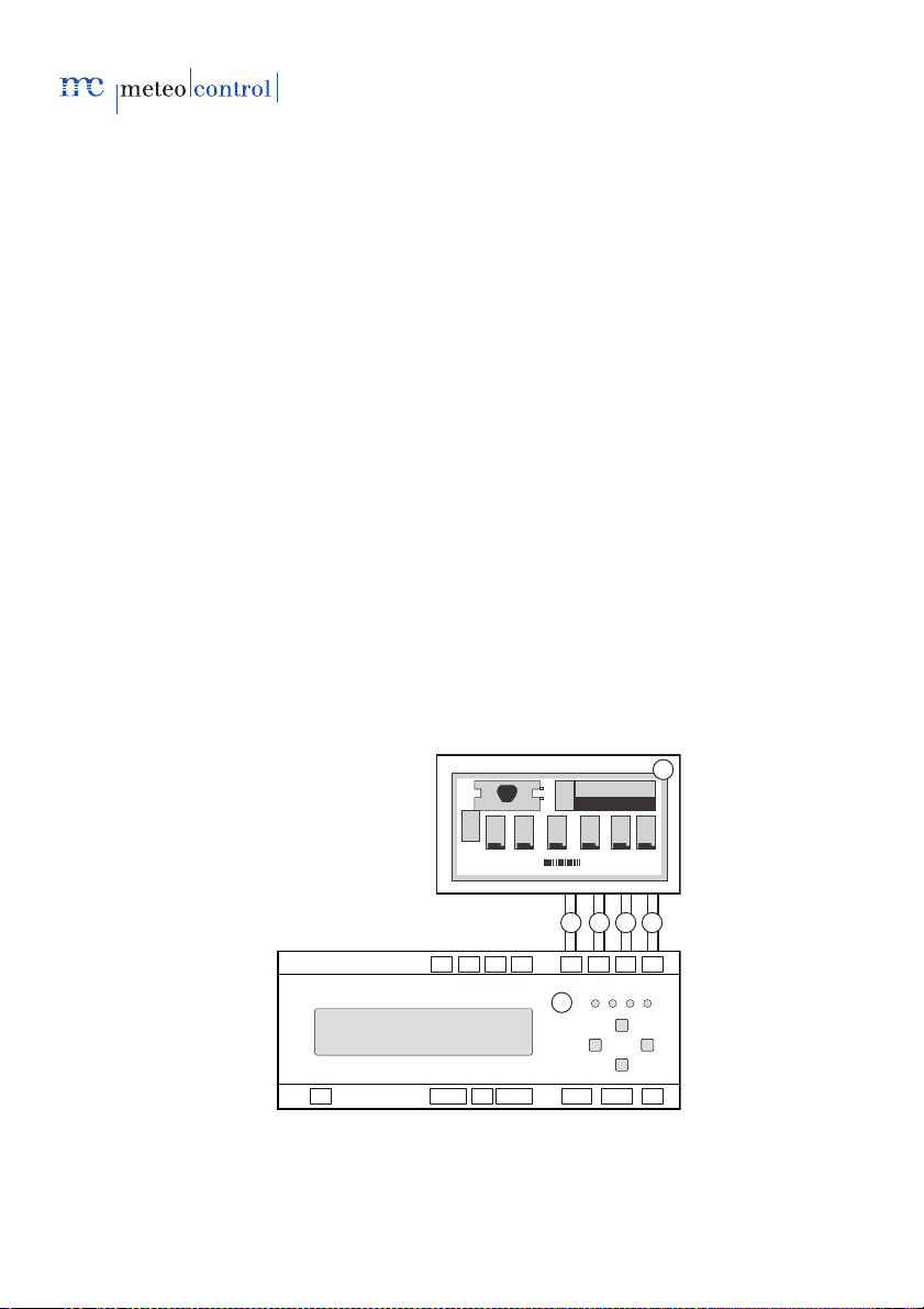
10.1.1 Ripple control receiver with WEB`log, digital inputs
The following example shows the connection of a ripple control receiver to
the internal digital inputs of the WEB`log.
When using the internal WEB`log inputs (WEB`log DIs), the use of feedback
signals is not supported.
62/78 meteocontrol Power Control 03082012 - en
Page 63

Fig. 40: Connection ripple control receiver <> WEB`log
+ - + -
- +- +- +- +- +- +- +- +
DI1DI1DI1DI1AI1AI2AI3AI4
RESET
Phone Ethernet RS485 RS232
24 V DO1
AC
230 V
110 V
N L
+ - + -
- +- +- +- +- +- +- +- +
DI1DI1DI1DI1AI1AI2AI3AI4
RESET
Phone Ethernet RS485 RS232
24 V DO1
AC
230 V
110 V
N L
+ - + -
- +- +- +- +- +- +- +- +
DI1DI1DI1DI1AI1AI2AI3AI4
RESET
Phone Ethernet RS485 RS232
24 V DO1
AC
230 V
110 V
N L
2
3
1
2
4
5
5
5
(1) Ripple control receiver (4) Digital input DI 3
(2) Digital input DI1 (5) Digital input DI 4
(3) Digital input DI2 (6) WEB`log
• If internal WEB`log inputs (WEB`log DIs) are used, feedback signals are
not supported.
• If Power Control is activated, the digital inputs must not be configured
otherwise by the WEB`log.
• Ripple control receivers with pulse output are not supported.
A PCU must be used for pulse evaluation.
10.1.2 WEB`log Pro master - slave
Fig. 41: Master-slave connection
(1)
WEB`log PRO Master
(2)
WEB`log PRO Slave
(4) Connection WEB`log PRO
master with Ethernet switch
(3) Ethernet switch (5) Connection WEB`log PRO slave
with Ethernet switch
• All WEB`log devices must be in the same network (subnet mask).
• Every WEB`log must be assigned its own IP address.
• A maximum of two WEB`log devices may be directly connected via a
• For more than two WEB`log devices, an Ethernet switch is required.
cross cable.
meteocontrol Power Control 03082012 - en 63/78
Page 64

1
2
3
6
7
9
12
13
14
16
8
11
15
4
5
10
17
11. The Power Control Unit (PCU)
The Power Control Unit (PCU) is an intelligent, powerful module with
different signal forms (digital, analogue, IEC 60870-5-101) can be recorded,
converted and transmitted to the WEB`log for active and reactive power
requirements.
Function:
• The PCU receives the requirements via inputs from the ripple control
receiver or main computer.
• The PCU prepares the requirements and sends them to the WEB`log.
• The WEB`log establishes the control values and sends them to the
inverters.
The PCU can only be operated in connection with WEB`log Pro. No PCU is
required to implement a reduction in active power without reactive power
procedure and without feedback to the energy supplier. This procedure,
P(DI) internal, can be achieved with the WEB`log via the WEB`log digital
inputs.
11.1 PCU Connections
Fig. 42: PCU front view with connections
64/78 meteocontrol Power Control 03082012 - en
Page 65

11.1.1 Description of the elements
Block I (terminals 1
-
13):
Block II (terminals 14
-
26):
Block III (terminals 27
-
Element Meaning
(1) Status display Inputs/outputs status
(2) IO type display Inputs/outputs configuration
(3)
+24V
+IO1 IO block 1
1-9 digital I/O
-IO 1
GND
(4)
+24V
+IO2 IO block 2
10-17 digital I/O
-IO 2
GND
(5)
39):
I_Out
+IO3 IO block 3
18-25 digital I/O
I_in
-IO 3
GND
(6) LED RS232 Activity of RS232
(7) LED RS485 Activity of RS485
(8) Status LED current status
(9) Power LED Status voltage supply
(10) Ethernet connection Interface for communication with
(11) Modbus connection Setting the PCU Modbus client ID
(12) Term RS485 Modbus termination to PCU
(13/14) RS485 connection Interface (double design) for
ground positive potential of the
voltage supply PCU
positive potential IO block I
digital inputs/outputs
negative potential IO block I
ground mass potential of the voltage
supply PCU
ground positive potential of the
voltage supply PCU
positive potential IO block II
digital inputs/outputs
negative potential IO block II
ground mass potential of the voltage
supply PCU
analogue output
positive potential IO block III
digital inputs/outputs
analogue input
negative potential IO block III
ground mass potential of the voltage
supply PCU
WEB`log PRO via TCP
High = hexadecimal high
(H`0x - H`Fx)
Low = hexadecimal low
(H`x0 - H`xF)
communication with WEB`log PRO
via Modbus RTU
Left: RxD
Middle: GND
Right: TxD
meteocontrol Power Control 03082012 - en 65/78
Page 66

Element Meaning
(15) Protect Write protect slide switch
(16) RS232 Interface for communication with the
(17) + -24V DC voltage supply
main computer (IEC)
11.1.1.1 Potentials and bridge assignment
The potential terminals in blocks I, II and III can be assigned differently
depending on the wiring. If the IO blocks are to be operated on the same
potential as the PCU, the following wiring must be observed:
• +24V: Terminals 1 and 14 have the same potential
• GND: Terminals 13, 26 and 39 have the same potential
Block I
• + 24V: (terminal 1) with +IO1 (terminal 2)
• GND: (terminal 13) with -IO1 (terminal 12)
Block II
• + 24V: (terminal 14) with +IO2 (terminal 15)
• GND: (terminal 26) with -IO2 (terminal 25)
Block III
If connected incorrectly, the device may be damaged.
Notice
– Observe precise clamping.
• GND: (terminals 1 or 14) with +IO3 (terminal 28)
• GND: (terminal 39) with -IO3 (terminal 38)
Note: If the potentials of RCR and CPU are to be disconnected, the
potentials of the connection blocks (+/-IOx) may not be
bridged with the PCU potential. In potential-free operation,
the plus and mass potential of the RCR on +/-IO of the
relevant connection block are required to ensure a safe
identification of the signals.
66/78 meteocontrol Power Control 03082012 - en
Page 67

11.1.1.2 Status LED
Symbol LED Meaning
RS232
RS485
IO type
IO status
On: Power supply connected
Off: No power supply connected or device
faulty
Flashing: Ready to operate
Off: Not ready to operate
Off: No data communication
Flashing: Data packets/byte received
or sent
Green: IO is configured as the input
Red: IO is configured as the output
if flashing, check IO, as possibly faulty
Off: IO is not used
On: Input or output is set
Off: Input or output is not set or is not used
meteocontrol Power Control 03082012 - en 67/78
Page 68

energize the power cable and take measures to prevent it from
11.2 PCU operating elements
11.2.1 Write protect slide switch
With the slide switch (see section 11.1.1, Description of the elements, No.
15), the configuration data of the Power Control can be protected against
write attempts.
To configure Power Control, the slide switch must be in OFF position.
After successful configuration, set the slide switch to ON to prevent abuse or
mistaken reconfiguration.
Note: If the write protection is set to ON, no configurations can be
made to Modbus devices. This affects the PCU as well as
possible additional devices and inverters, which are
connected via Modbus.
11.2.2 Modbus address coding switch
With the address coding switch, the Modbus client ID of the PCU is set.
The client ID is required for the configuration of the PCU in the WEB`log.
11.2.3 Modbus bus termination switch
With the termination switch, the Modbus can be physically completed.
This is only required if the PCU is operated in the Modbus RTU mode as the
last device.
11.3 Installation
11.3.1 Safety instructions for installation
The data loggers must only be connected by a qualified electrician.
• All cables must be connected or disconnected only when de-energized
68/78 meteocontrol Power Control 03082012 - en
Warning
Plant live!
– Death in the event of electric shock or severe injury with
irreversible damage.
– De-
being re-energized.
Page 69

Notice
Observe cabling!
– Material damage from incorrect cable connections to the system
and its immediate environment.
• Use suitable wire end ferrules with flexible cables
• Tighten all clamped connections with a suitable tool and check that
contact is made and that the connection is secure
• Only use the specified cables.
meteocontrol Power Control 03082012 - en 69/78
Page 70

1
2
5
6
7
1
1
3
2
4
11.3.2 Mounting
11.3.2.1 Installing device on top-hat rail
Hook the device over the upper edge of the top-hat rail and press it on until
the clamp snaps into place.
To remove the device, pull the clamp down with a screwdriver and take the
device off the top-hat rail.
Fig. 43: Installation on a top-hat rail
(1) Device (5) Screwdriver
(2) Top-hat rail (6) Releasing the clamp
(3) Upper edge of top-hat
rail
(4) Pressing on the device
(7) Removing the device
70/78 meteocontrol Power Control 03082012 - en
Page 71

11.3.2.2 Mounting the device on a wall
1
5
6
2
1
2
3
4
Insert two screws 90 mm apart on the wall. Mount the device so that the
screws lie in the recesses of the device. Push the device down a short way
and check that it is seated correctly.
To remove the device, push it up a short way and take it off to the front.
Fig. 44: Wall mounting using screws
(1) Device (4) Securing the device
(2) Fastening screws (5) Loosening the device
(3) Mounting the device (6) Removing the device
meteocontrol Power Control 03082012 - en 71/78
Page 72
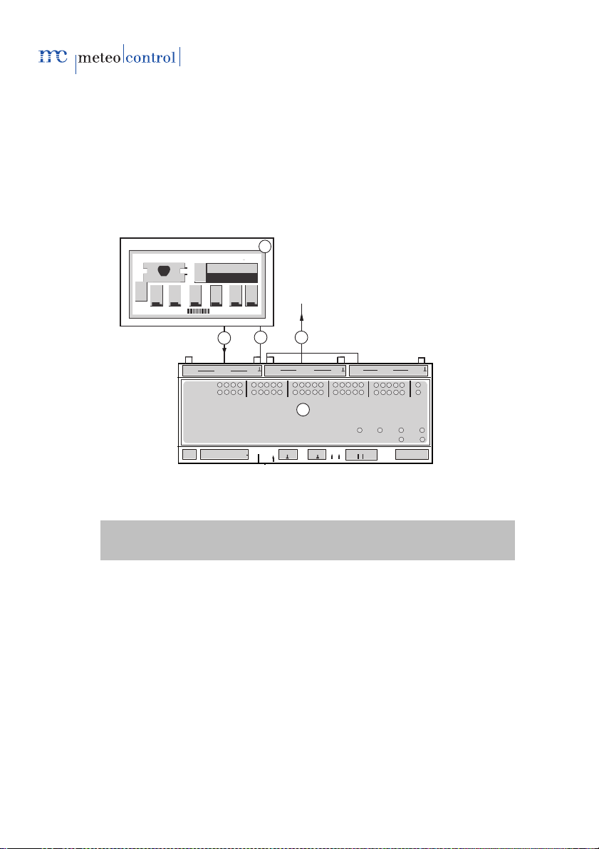
1
4
+
- +
low
Digital I/0
Protect
Ethernet
RS485
RS232
Term
A B
24V
RS485
A B
Modbus
1
24V
24V
+
I02
+
I01
+
Digital I/0
Digital I/0
9
10
17
18
25
I03
I_out
I/0-3
I/0-2
I/0-1
I01
-
-
-
I02
I03
I_in
2
3
high
5
11.3.3 Connection options
11.3.3.1 Ripple control receiver with PCU, digital inputs
The following example shows the connection of a ripple control receiver
(RCR) to the digital inputs of the PCU.
The ripple control receiver and the PCU are in the same potential here. The
bridge assignment block I, block II and block III can be found in the table
(see section 11.1.1 Description of the elements). There is a mass connection
between RCR and PCU.
Fig. 45: Connection ripple control receiver <> PCU (digital)
(1) Ripple control receiver (4) PCU
(2) Signal inputs, digital (5) Mass potential
(3) Signal outputs, digital
As most ripple control receivers do not have any feedback inputs, the digital
PCU signal outputs (feedback outputs) do not lead to the ripple control
receiver, but are designed separately. The feedback signals from the PCU
must be further processed in accordance with the system concept.
Note: The signal inputs and outputs are stated as examples. The
wiring of the PCU must correspond to the PCU configuration.
72/78 meteocontrol Power Control 03082012 - en
Page 73
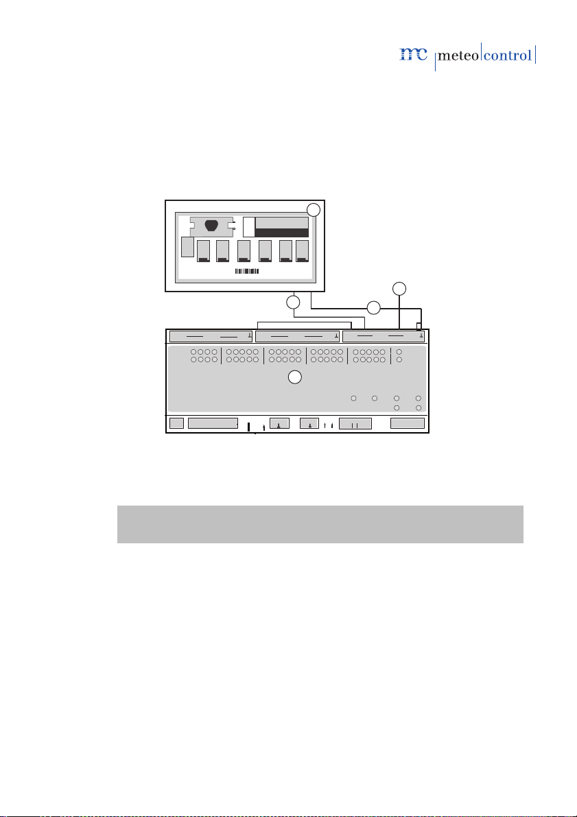
11.3.3.2 Ripple control receiver with PCU, analogue input
1
3
+
- +
low
Digital I/0
Protect
Ethernet
RS485
RS232
Term
A B
24V
RS485
A B
Modbus
1
24V
24V
+
I02
+
I01
+
Digital I/0
Digital I/0
9
10
17
18
25
I03
I_out
I/0-3
I/0-2
I/0-1
I01
-
-
-
I02
I03
I_in
2
high
4
5
The following example shows the connection of a ripple control receiver to
the analogue power input of the PCU. The ripple control receiver and the
PCU are in the same potential in the example. The assignment of the bridges
block III can be found in the table (see section 11.1.1 Description of the
elements). There is a mass connection between ripple control receiver and
PCU.
Fig. 46: Connection ripple control receiver <> PCU (analogue)
(1) Ripple control receiver (4) Signal output, analogue
(2) Signal input, analogue (5) Mass potential
(3) PCU
As most ripple control receivers do not have analogue feedback inputs, the
analogue PCU signal output (feedback output in the figure: item 4) does not
lead to the ripple control receiver, but is designed separately. The feedback
signal from the PCU must be further processed in accordance with the plant
concept.
meteocontrol Power Control 03082012 - en 73/78
Page 74

1
3
+
- +
low
Digital I/0
Protect
Ethernet
RS485
RS232
Term
A B
24V
RS485
A B
Modbus
1
24V
24V
+
I02
+
I01
+
Digital I/0
Digital I/0
9
10
17
18
25
I03
I_out
I/0-3
I/0-2
I/0-1
I01
-
-
-
I02
I03
I_in
high
2
11.3.3.3 Main computer, RS232 IEC interface with PCU
The following example shows the connection of a ripple control receiver to a
main computer.
Fig. 47: Connection main computer <> PCU (IEC)
(1) Central computer (3) PCU
(2) Signal input, IEC main
computer
11.3.3.4 Connection PCU with WEB`log PRO, Modbus RTU
The PCU is connected to the WEB`log via RS485.
The selection of the connection socket depends on the protocol of the
inverters used, as Modbus and proprietary protocols cannot be operated via
the same connection.
Proprietary WR protocol to RS485 -> PCU to RS232/RS422 connection
Modbus WR protocol to RS485 -> PCU and WR to RS485 connection
be found in the WEB`log Quick Reference Guide.
Details on the configuration of the RS422 socket as an RS485 interface can
74/78 meteocontrol Power Control 03082012 - en
Page 75
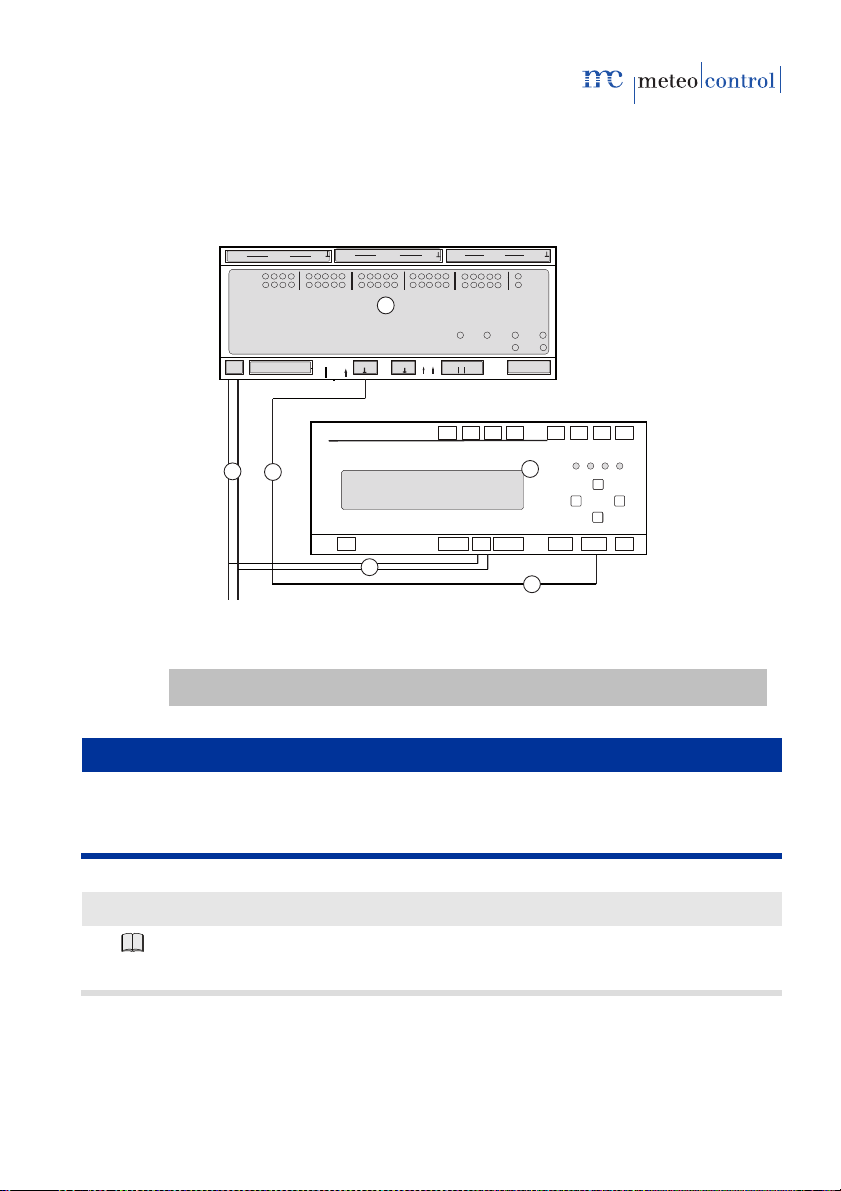
The following example shows the connection of the PCU to WEB`log PRO in
1
+ - + -
- +- +- +- +- +- +- +- +
DI1DI1DI1DI1AI1AI2AI3AI4
RESET
Phone Ethernet RS485
RS232/
24 V DO1
AC
230 V
110 V
N L
4
+ -
+
- +
low
Digital I/0
Protect
Ethernet
RS485
RS232
Term
A B
24V
RS485
A B
Modbus
1
24V
24V
+
I02
+
I01
+
Digital I/0
Digital I/0
9
10
17
18
25
I03
I_out
I/0-3
I/0-2
I/0-1
I01
-
-
-
I02
I03
I_in
2
3
RS422
3
4
high
the event that WR are connected to the RS485 with a proprietary protocol.
For the connection of the PCU to the WEB`log PRO (see Fig. below), the
connection cable (No. 4) must be configured in accordance with section
6.3.6.1.
Fig. 48: Connection PCU <> WEB`log Pro
(1) PCU (3) DC 24V power supply
(2) WEB`log Pro (4) Modbus RTU
Notice
If voltages of more than 24 V DC are applied to the digital inputs, this can
destroy the respective measuring inputs.
– Ensure that only voltages of up to 24 V DC are applied.
Further information about this topic:
Operating manual
WEB`log PRO installer Installation, mounting
meteocontrol Power Control 03082012 - en 75/78
Page 76
12. The plant control circuit/GCP control
GCP controlling ensures that the changes to the power data are
compensated by the PV systems on the way to the GCP (NS or MS) and the
requested requirements are implemented on the GCP. Only the nominal
power of the transformer needs to be known.
13. Power procedures overview
P(DI) WEB`log internal + + +
P (DI) *1 +
P(AI) *1 +
Inverter internal driver-
cos φ (DI) *1
cos φ (AI) *1
cos φ fixed
Q (DI) *1
Q (AI) *1
Q fixed + + +
cos φ (P) *2
cos φ (U) *2
Q (U) *2
Inverter internal
Q GCP control *2
cos φ GCP control *2
*1: in connection with PCU
*2: in connection with GCP or PCU with main computer
WEB`log
Basic 100
Active power procedure
Reactive power procedure
+
+ + +
Table 1: Overview implemented power procedures per device type
76/78 meteocontrol Power Control 03082012 - en
WEB`log
Light+ 20
GCP control
WEB`log
Pro Unlimited
dependent
+
+
+
+
+
+
driver-
dependent
+
+
Page 77

Glossary
GCP grid connection point 26
PQA power quality analyser 26
RTU Modbus RTU mode (RemoteTerminalUnit) 20
TCP Modbus TCP mode (TCP/IP) 20
14.
15. List of figures
Fig. 1: Functionality PCU<>Power Control .................................................................... 13
Fig. 2: Functionality Power Control ................................................................................ 14
Fig. 3: Power Control settings ....................................................................................... 17
Fig. 4: Selection of the Modbus settings and Modbus device types .............................. 18
Fig. 5: Assignment Modbus client ID to the device type ................................................ 20
Fig. 6: General information device configuration ........................................................... 22
Fig. 7: Configuration of analogue inputs/outputs ........................................................... 22
Fig. 8:Configuration of digital inputs and outputs ........................................................... 24
Fig. 9: Configuration selection power quality analyser .................................................. 25
Fig. 11: Update PCU Firmware ..................................................................................... 26
Fig. 12: Power Control online values ............................................................................. 27
Fig. 13: WEB`log master without slaves ........................................................................ 27
Fig. 14: WEB`log master with broadcast to all slaves .................................................... 28
Fig. 15: WEB`log master with selected slaves............................................................... 28
Fig. 16: WEB`log master with slave groups ................................................................... 28
Fig. 17: Definition WEB`log slave general broadcast .................................................... 29
Fig. 18: Definition WEB`log slave single message ........................................................ 30
Fig. 19: Definition WEB`log slave group broadcast ....................................................... 30
Fig. 20: Power control system data ............................................................................... 31
Fig. 21: Enabling Power Control .................................................................................... 31
Fig. 22: Active power procedure selection ..................................................................... 33
Fig. 23: Reactive power procedure selection................................................................. 33
Fig. 24: Active power procedure control P(DI) ............................................................... 34
Fig. 25: Active power procedure control P(AI) ............................................................... 36
Fig. 26: Active power procedure P(DI) internal .............................................................. 38
meteocontrol Power Control 03082012 - en 77/78
Page 78

Fig. 27: Reactive power procedure cos φ(DI) ............................................................... 39
Fig. 28: Example curve cosφ(AI) ................................................................................... 41
Fig. 29: Reactive power procedure control cos φ(AI) .................................................... 42
Fig. 30: Reactive power procedure control cos φ Fix .................................................... 44
Fig. 31: Reactive power procedure control Q(DI) .......................................................... 45
Fig. 32: Power procedures P(DI) and Q(DI) combined ................................................. 47
Fig. 33: Curve Q(AI) ...................................................................................................... 49
Fig. 34: Reactive power procedure control Q(AI) .......................................................... 50
Fig. 35: Reactive power procedure control Q Fix .......................................................... 52
Fig. 36: Reactive power procedure control Q(U) ........................................................... 53
Fig. 37: Reactive power procedure control cosφ(P) ...................................................... 54
Fig. 38: Reactive power procedure control cos φ(U) ..................................................... 55
Fig. 39: GCP control circuit configuration ...................................................................... 57
Fig. 40: Connection ripple control receiver <> WEB`log ............................................... 63
Fig. 41: Master-slave connection .................................................................................. 63
Fig. 42: PCU front view with connections ...................................................................... 64
Fig. 43: Installation on a top-hat rail .............................................................................. 70
Fig. 44: Wall mounting using screws ............................................................................. 71
Fig. 45: Connection ripple control receiver <> PCU (digital) ......................................... 72
Fig. 46: Connection ripple control receiver <> PCU (analogue) .................................... 73
Fig. 47: Connection main computer <> PCU (IEC) ....................................................... 74
Fig. 48: Connection PCU <> WEB`log Pro.................................................................... 75
Table 1: Overview implemented power procedures per device type ............................. 76
78/78 meteocontrol Power Control 03082012 - en
 Loading...