

SAT RC 09
EN
5040273800
INSTALLATION MANUAL
CAUTION
- Only carry out the operations described in this manual.
- The installer is not authorized to remove the warranty seals or to access the interior parts of the products or accessories.
- The installer is not authorized to modify and/or adapt the product or the relative accessories.
- The manufacturer declines all liability for damage to persons and/or property caused by incorrect installation of the product.
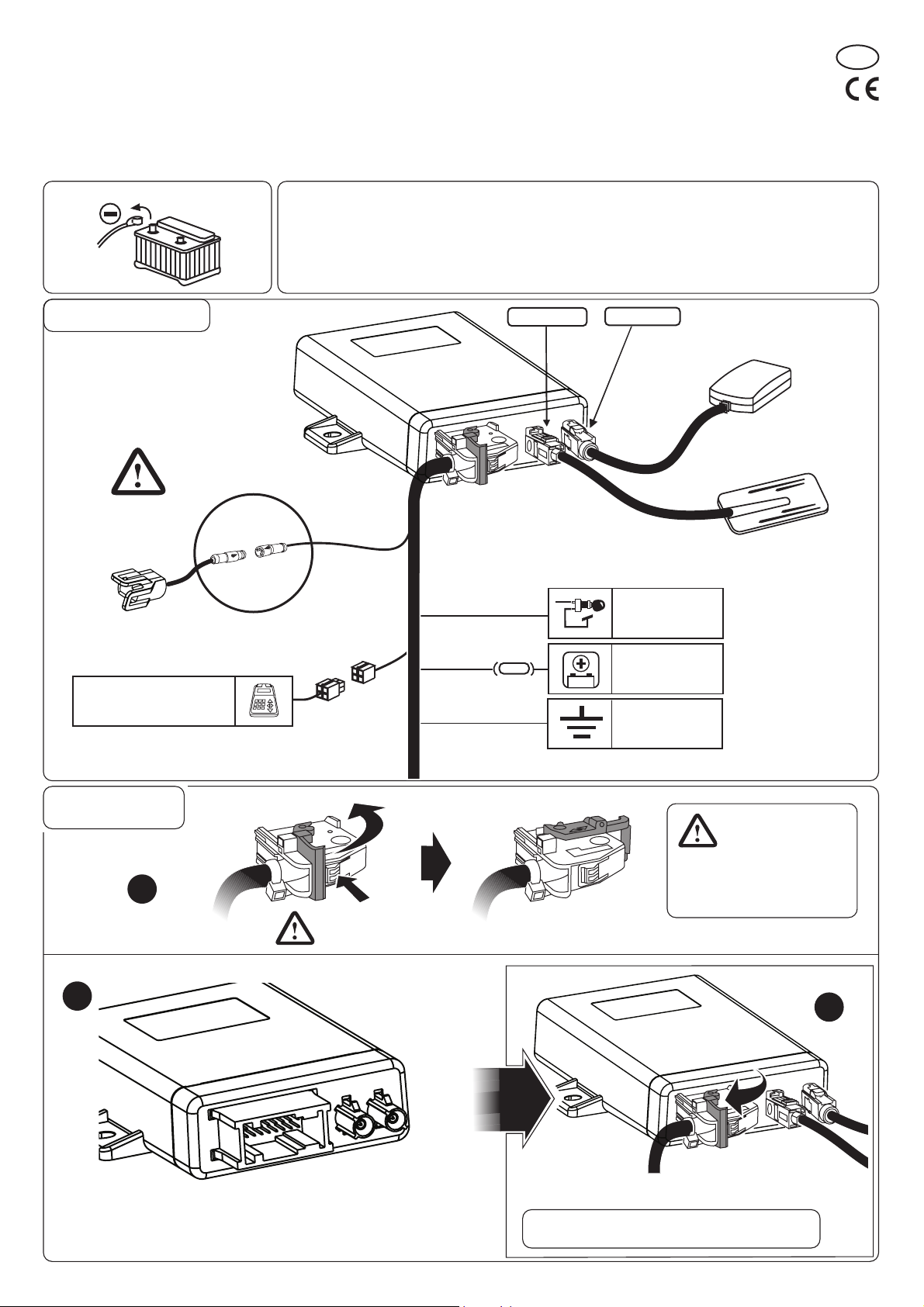
DISCONNECT THE VEHICLE’S BATTERY
GENERAL LAYOUT
TECHNICAL SPECIFICATIONS
Dimensions and weight:....................................................................................104X75X27, 168g
Power supply voltage:................................................................................................12 VDC
Temperature:..........................................................................................................-25º+70ºC
Power input*:.............................................................................................................<2mA
*With the peripheral device connected, the GPS off, Sat Programmer disconnected and the internal
buffer battery charged.
Maximum current:.............................................................................................................<210mA
MAROON
DARK BLUE
See pic. 5
GPS
ANTENNA
GSM
ANTENNA
PROGRAMMER
CONNECTOR
CONNECTIONS
PHASE
1
Fig.2
PHASE
2
SAT
PRESS
TO RELEASE
+15
+12
5A
*
GND
* : MANDATORY
IGNITION
KEY POSITIVE
(+15)
BATTERY
POSITIVE
(+12V)
GROUND
Fig.1
Release and position the lever
as shown in the figure before
connecting the 18-pin loose
connector to the terminal.
PHASE
3
Connect the connectors
to the terminal
Fig.3
Lock the connector to the terminal by positioning the lever
as shown in the figure.
WARNING: make sure that the connector is inserted
and locked to the terminal in the correct way.
Fig.4
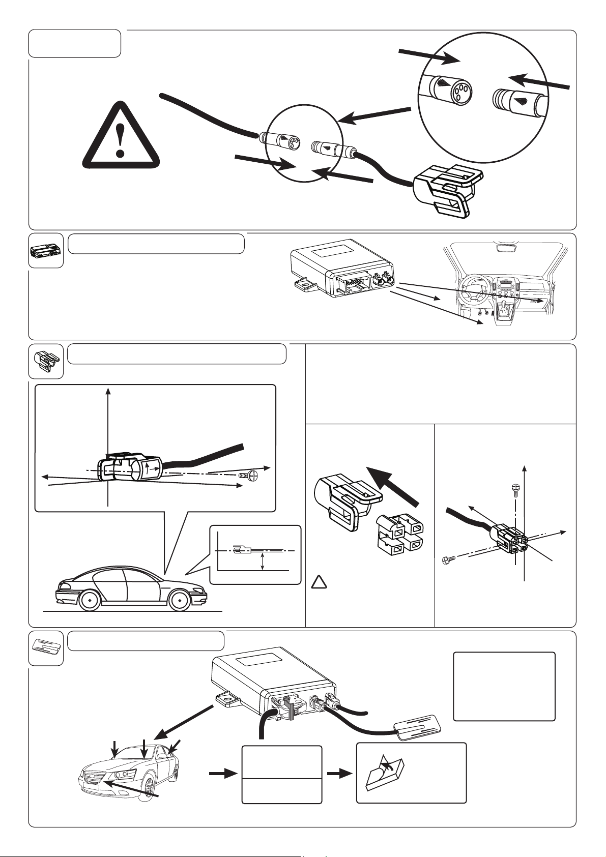
CONNECTION
CRASH SENSOR
CLICK!
CAUTION!
CHECK THE CORRECT
CONNECTION
HOW TO POSITION THE DEVICE
• Position the device in a concealed part of the vehicle, inside the
passenger compartment
• To allow the diagnosis and testing operations to be carried out without
difficulty, it is essential to install the device in a position where it can
be easily reached with the cable of the Sat programmer.
• Do not install the device under a mat, where it could be trodden on or
crushed by a load.
• It is advisable to lock the device to a rigid part of the vehicle.
HOW TO POSITION THE CRASH SENSOR
TOP OF
Y
VEHICLE
LEFT SIDE
OF VEHICLE
X
P
O
FRONT
T
RIGHT SIDE
OF VEHICLE
FRONT OF
VEHICLE
CLICK!
Use the supplied spacer to install the sensor on a flat surface, opposite
the fastening tabs (e.g. longitudinal frame members on the PASSENGER’S
SIDE, surfaces BELOW the sensor).
The sensor must NOT be turned. Comply with the position indicated on the
sticker affixed to the side of the sensor.
FIXING WITH SPACER
HOW TO INSERT THE
SPACER
Fig.5
Fig.6
FIXING IN THE VEHICLE
TOP OF
Y
VEHICLE
FRONT OF
VEHICLE
• Fix the sensor temporarily in place
with the screw.
• Check the position of the sensor by
means of the relative Sat Programmer
menu.
• Fix the sensor permanently in place.
X
HOW TO CONNECT THE GSM ANTENNA
OK
OK
ONCE YOU HAVE CHOSEN THE POSITION FOR THE ANTENNA, MAKE SURE THAT THE RECEPTION IS GOOD BEFORE FIXING IT IN PLACE:
- CONNECT THE SAT PROGRAMMER AND TEST TO MAKE SURE THAT EVERYTHING WORKS PROPERLY BY MEANS OF THE APPROPRIATE FUNCTION (CONSULT THE RELATIVE MANUAL).
OK
OK
RIGHT SIDE
Y
LEFT SIDE
0
X
Pay particular attention to
!
the direction in which
OF VEHICLE
OF VEHICLE
X
the spacer is inserted.
Fig. 7 Fig. 8 Fig. 9
THE ANTENNA IS RESIN-
COATED AND CAN
THEREFORE BE INSTALLED
ON THE OUTSIDE OF THE
VEHICLE (E.G. UNDER THE
MUDGUARDS, IN A
HEADLIGHT......)
IT MUST NOT BE
VISIBLE OR EASILY
ACCESSIBLE FROM
THE OUTSIDE
DO NOT COVER WITH
PARTS OR METALLIC
PAINTS
GSM
ANTENNA
CAREFULLY
CLEAN THE
FIXING SURFACE
Fig. 10

HOW TO CONNECT THE GPS ANTENNA
OK
OK
OK
OK
IT MUST NOT BE
VISIBLE OR EASILY
ACCESSIBLE FROM
THE OUTSIDE
HOW TO FIX THE ANTENNA:
- ON METAL PARTS WITHOUT THE USE OF THE DOUBLE-SIDED
ADHESIVE MATERIAL (THE ANTENNA IS MAGNETIC)
- ON PLASTIC PARTS USING THE DOUBLE-SIDED ADHESIVE
MATERIAL SUPPLIED IN THE KIT
DO NOT COVER WITH
PARTS OR METALLIC
PAINTS
ONCE YOU HAVE CHOSEN THE POSITION FOR THE ANTENNA,
MAKE SURE THAT THE RECEPTION IS GOOD BEFORE FIXING
IT IN PLACE:
- DRIVE THE VEHICLE TO AN OPEN SPACE, WELL AWAY
FROM BUILDINGS OF A CERTAIN HEIGHT
- CONNECT THE SAT PROGRAMMER AND TEST TO MAKE
SURE THAT EVERYTHING WORKS PROPERLY BY MEANS
OF THE APPROPRIATE FUNCTION (CONSULT THE RELATIVE
MANUAL).
GPS
ANTENNA
CAREFULLY
CLEAN THE
FIXING
SURFACE
90°
NO
OK
KOOK
THE ANTENNA IS RESIN-
COATED AND CAN
THEREFORE BE
INSTALLED ON THE
OUTSIDE OF THE VEHICLE
(E.G. UNDER THE
MUDGUARDS, IN A
HEADLIGHT......)
Fig. 11
Meta System S.p.A.
Model: SAT RC 09
FCC ID.: P3O97802
This device complies with Part 15 of the FCC rules subject to the following two conditions:
1) This device may not cause harmful interference.
2) This device must accept all interference received, including interference that may cause undesired operation.
NOTE: This equipment has been tested and found to comply with the limits for a Class B digital device, pursuant
to Part 15 of the FCC Rules. These limits are designed to provide reasonable protection against harmful
interference in a residential installation. This equipment generates, uses and can radiate radio frequency
energy and, if not installed and used in accordance with the instructions, may cause harmful interference
to radio communications. However, there is no guarantee that interference will not occur in a particular
installation.
If this equipment does cause harmful interference to radio or television reception, which can be determined
by turning the equipment off and on, the user is encouraged to try to correct the interference by one or
more of the following measures:
- Reorient or relocate the receiving antenna.
- Increase the separation between the equipment and receiver.
- Connect the equipment into an outlet on a circuit different from that to which the receiver is connected.
- Consult the dealer or an experienced radio/TV technician for help.

R&TTE Declaration Of Conformity (DoC)
0470
We: Meta System S.p.A.
with the address:
Via Majakovskij 10 b/c/d/e 42124 Reggio Emilia –Italy
Declare
Under own responsibility that the product:
SAT RC 09
To which this declaration relates is in conformity with the essential
requirements and other relevant requirements of the R&TTE Directive
(1999/5/EC).
This product is in conformity with the following standards
- Health & Safety (art.3.1) EN 60950-1 –
- EMC (art.3.2) ETSI EN 301 489-1/-7/-19
- Spectrum ETSI EN 301 511
- Human exposure EN62311
According to Directive 1999/5/CE
Technical Director
Lasagni
Cesare
Reggio Emilia , 15/03/2010
 Loading...