

Page 1

EN
PARKING SENSOR FOR FRONT
AND REAR APPLICATIONS
OPERATING PRINCIPLE
The product is an electronic device conceived to park the vehicle easier.
This system has been designed for application on the front or rear bumper of the vehicle.
The front system requires the push button (Y) supplied in the kit, to be connected to the slot 3 of the control unit
(general diagram on page 13).
The parking sensor is based on the principle of the sound wave re ection when an obstacle is detected.
Knowing the speed at which sound propagates in the air and measuring the time that elapses between the emission
of a sequence of pulses and its reception, after it has been re ected by an obstacle, it is then possible to calculate the
distance of the obstacle itself from the sound energy source (sensor).
For this purpose, there are 4 sensors allowing to completely protect the vehicle’s surfaces.
Each sensor consists of an ultrasounds capsule that also acts as a receiving element of the re ected wave.
An intermittent beep warns about the approaching of the vehicle to an obstacle.
The nearer the car gets to the obstacle the faster the beeping becomes, until turning into a continuous sound when
the minimum safety distance is reached.
INDEX
Kit contents ..........................................................................................................................................Pag. 12
Installation tools ................................................................................................................................Pag. 12
General wiring diagram ..................................................................................................................Pag. 13
Technical features ..............................................................................................................................Pag.13
Painting the capsules and the relevant supports ....................................................................Pag. 13
General recommendations before starting the installation ................................................Pag. 14
Sensors xing positions .....................................................................................................................Pag. 14
- Installation with the ISH system (Internal Sensor Holder) ......................................Pag. 15
- Installation with the ESH system (External Sensor Holder) .....................................Pag. 16
Programming ........................................................................................................................................Pag. 17
Masking procedure .............................................................................................................................Pag. 17
Reducing the system’s performance ............................................................................................Pag. 18
Reducing the side sensors detection ...........................................................................................Pag. 18
System modes for the front application .....................................................................................Pag. 18
Recording the speed threshold ....................................................................................................Pag. 18
Calibration ..............................................................................................................................................Pag. 19
Additional functions ...........................................................................................................................Pag. 19
-
Car stereo mute (for front and rear systems, activated through the push button) .........Pag. 19
System’s cut-o for trailer connection to the vehicle ............................................................Pag. 19
Diagnostics .............................................................................................................................................Pag. 20
How to use the front system ...........................................................................................................Pag. 20
How to use the rear system ............................................................................................................Pag. 20
11
Page 2
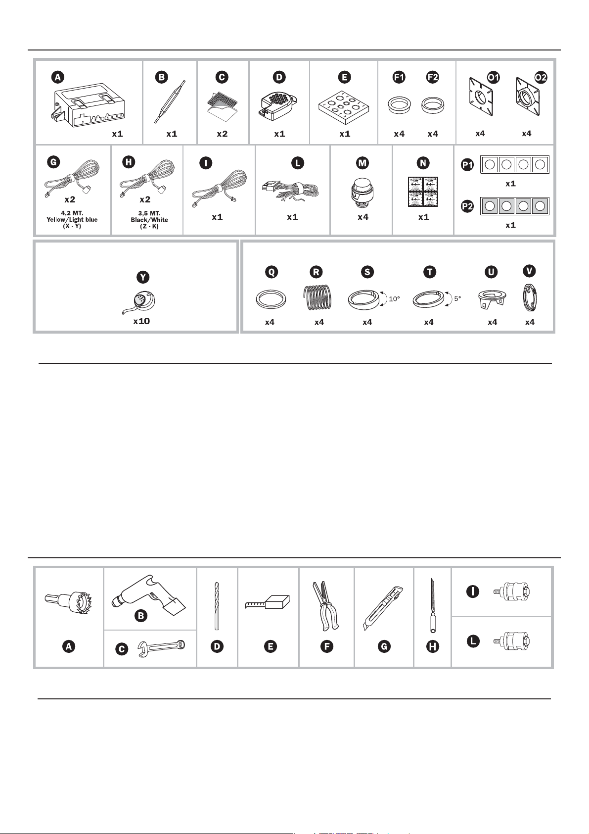
KIT CONTENTS
OPT: ABP05580
Front installation accessory
LEGEND
The Kit Includes
A - Control Unit
B - Screwdriver for calibration
C - Adhesive velcro
D - Loudspeaker
E - Painting template
F - Silicone ring
G - 4,2 M. sensor’s wire harness
H - 3,5 M. sensor’s wire harness
I - Loudspeaker’s wire harness
L - Main ECU’s wire harness
M - Capsules
N - Drilling templates
ISH installation accessories
O - Sensors holders
P - Adhesive supports
ESH installation accessories
Q - Silicone ring for spring
R - Spring
S - 10° slanting device
T - 5° slanting device
U - Ring nut
V - Spring stopper
OPT: ABP0214 - ESH installation accessories
Front installation accessory
Y - ON-OFF Push button/LED for front
application the front parking sensors
LEGEND
A - Ø19 mm hollow cutter
B - Drilling machine
C - Ø2,5 mm drill
D - Roll-up measuring tape
INSTALLATION TOOLS
E - Pliers
F - Cutter
G - Small round le
12
Page 3
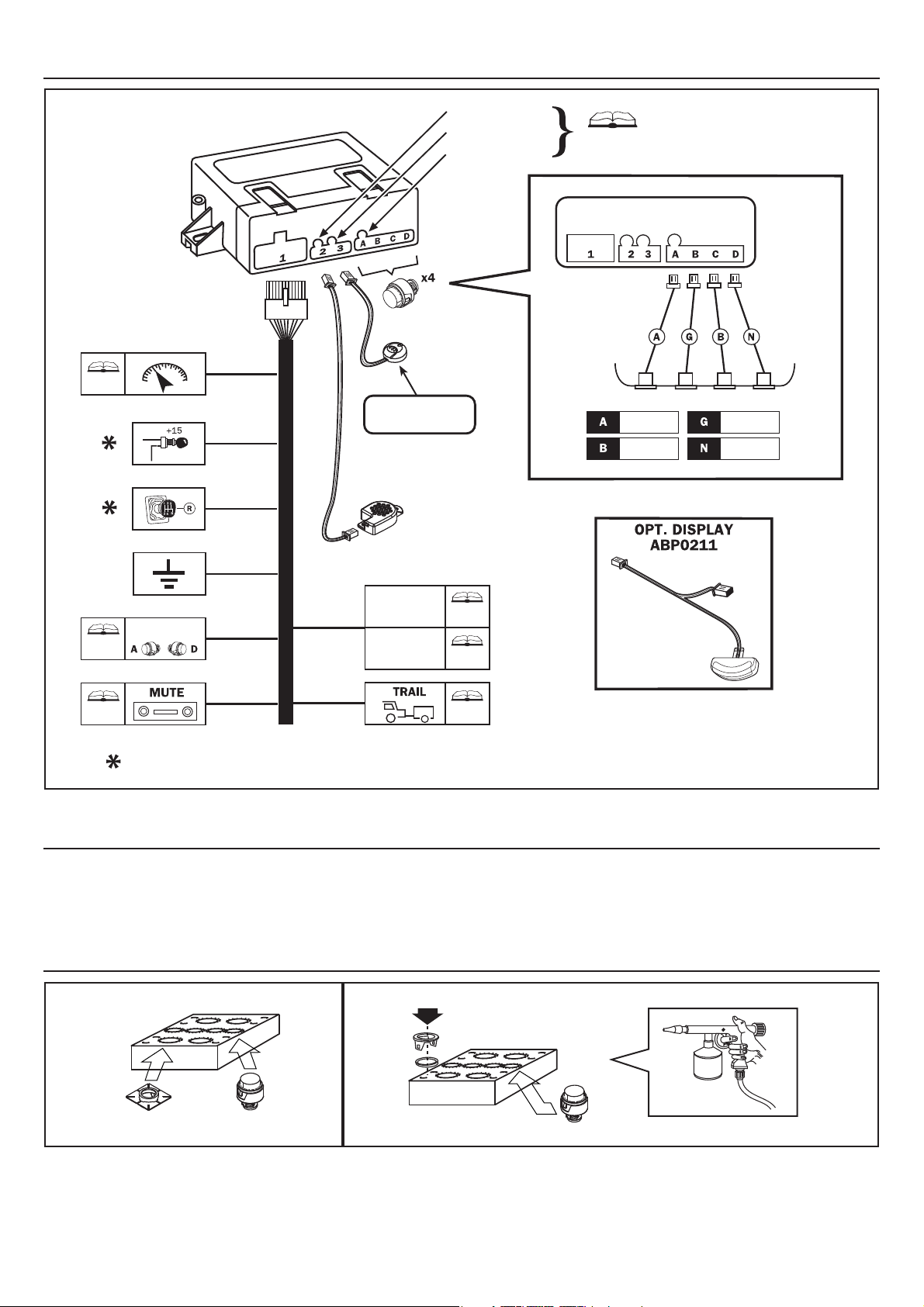
GENERAL WIRING DIAGRAM
OFFSET
SOUND
SENSITIVITY
Page 19
Fig. 1
Left side
of bumper
LIGHT BLUE
WHITE
YELLOW
BLACK
Page 18
Page 18
Page 19
SPEEDOMETER SIGNAL
REDUCTION OF
SENSITIVITY
GREEN/BLACK
RED
GREY
BLACK
YELLOW
PURPLE
RED/DARK BLUE
BROWN
FRONT INSTALLATION
ACCESSORY
OPT: ABP05580
REDUCTIONS OF
SYSTEM’S
PERFORMANCE
READING
MASKING
Page 18
Page 17
Page 19
IN CASE OF INSTALLATION ON A REAR BUMPER, CONNECT THE RED AND GREY WIRES TOGETHER
Right side
of bumper
TECHNICAL FEATURES
Power ..............................................................................................................12 Vcc (10V-15V)
Current absorption with the system active ........................................................< 50mA
PAINTING THE CAPSULES AND THE RELEVANT SUPPORTS
Fig. 2a Fig. 2b
Before assembling the components of the sensors it is advisable to paint the capsules and supports in the same colour of the car.
Use the carton mask, included into the kit, for painting in order to prevent paint from getting on parts of the capsule which would
alter its performance.
Speci c primers must be applied rst before painting; make sure the paint is completely dry before assembling the components.
13
Page 4
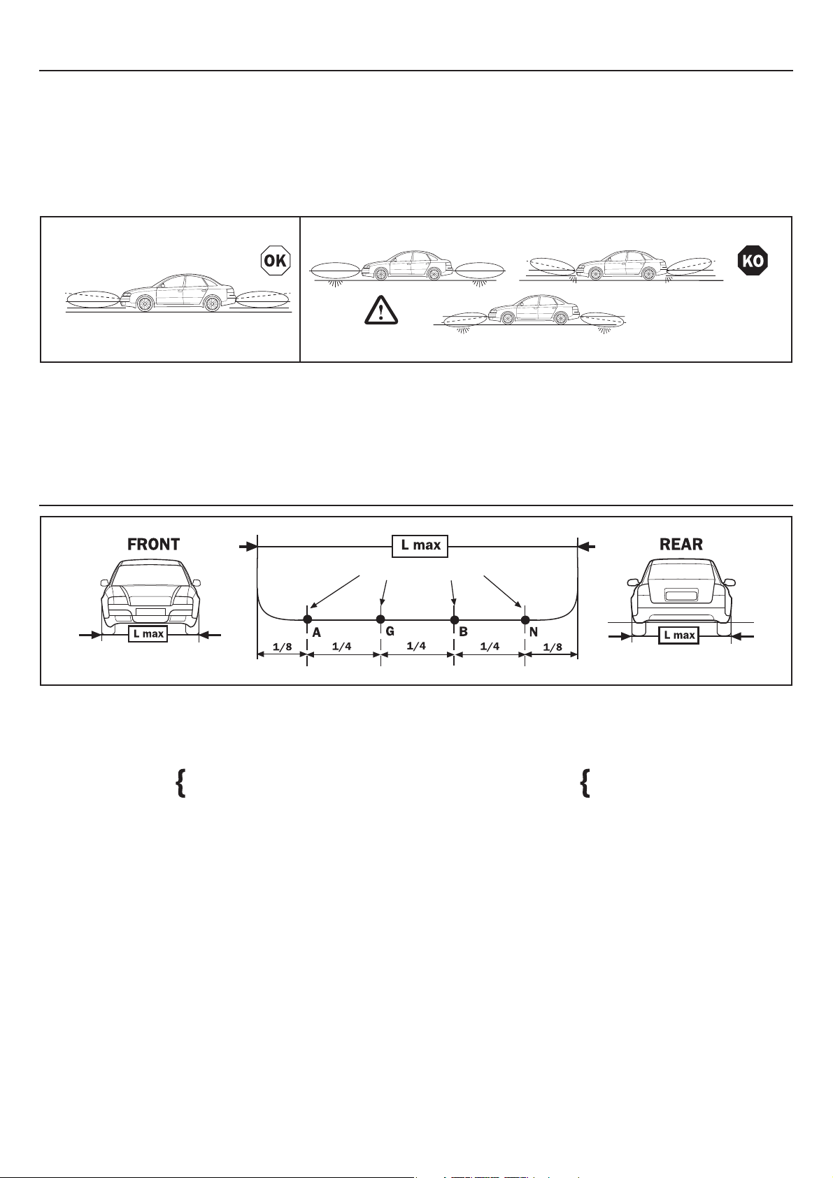
GENERAL RECOMMENDATIONS BEFORE STARTING THE INSTALLATION
The performance and accuracy of the system are strongly in uenced by the position and orientation of the sensors. For this reason
certain conditions have to be checked before starting the installation:
• On the positions chosen to place the sensors the bumper must provide enough depth internally and room for assembly
without any forcing.
• Follow the positioning instructions and the tips on the accessories to be used, depending on the height and shape of the
bumper.
It is extremely important to t the sensors on the bumper and keeping a height that can vary from a maximum of about 65 cm to a
minimum of 35 cm. It is important that the sensors are as vertical as possible from the ground.
Fig. 3a Fig. 3b
For this reason two types of spacer are part of the optional ESH pack (ABP0214): one has 5° inclination A and one a 10° inclination
B (see installation with ring nut accessories S and T); they are indispensable to realign any incorrect inclination of the sensor, due
to the shape of the bumpers. If, even with both spacers, it is impossible to get a vertical position, then it is preferable to use the one
that allows to reach the highest position. If the bumper allows for a vertical position, the capsule xing ring nut can be used without
any spacer and in these conditions it is also possible to use the ISH system (see installation with ISH g.5a and g.5b).
SENSORS FIXING POSITIONS
SENSORS POSITIONS
Fig. 4
The distance between the sensors can vary from a minimum of 30 cm to a maximum of 70 cm. The important thing is that there
must be the same distance between them all, likewise the external distances (as much as possible). If feasible it is advisable to position them as shown in the gure. When evaluating the position of the capsules it is important to consider their range of action:
internal: 110 cm approx. internal: 150 cm approx.
external: 90 cm approx. external: 100 cm approx.
FRONT REAR
14
Page 5
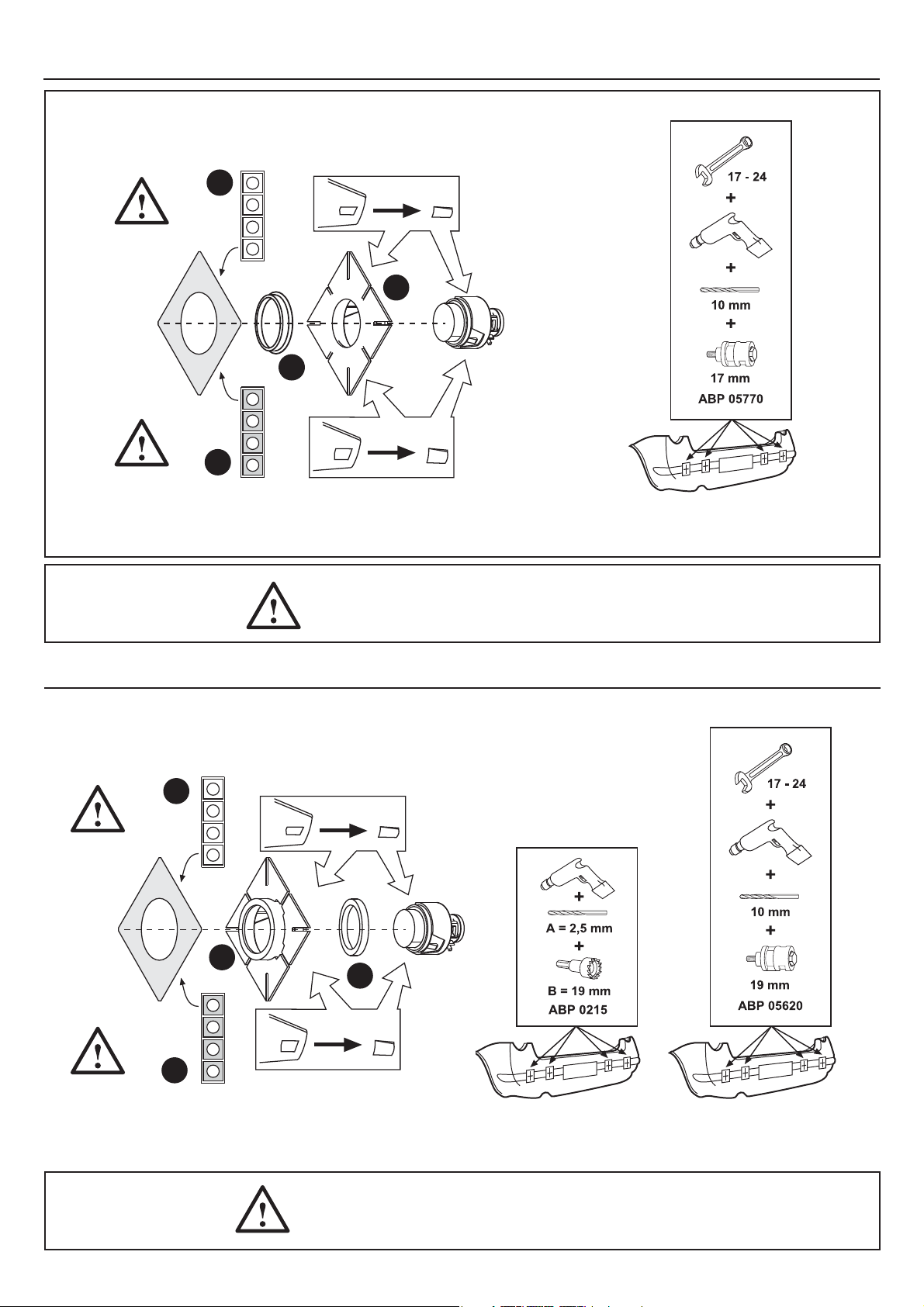
INSTALLATION WITH THE ISH SYSTEM (WITHOUT INTERNAL SENSOR HOLDER)
CHOOSE THE RIGHT BIADHESIVE
FOR THE DIFFERENT THICKNESS
OF THE BUMPERS
P1
WHITE
(1,1 mm)
O1
F1
RED
(1,5 mm)
P2
CHOOSE THE RIGHT BIADHESIVE
FOR THE DIFFERENT THICKNESS
OF THE BUMPERS
ONLY PLASTIC BUMPERS
Fig. 5a
NOTE: DRILL THE BUMPER FROM THE OUTSIDE
INSTALLATION WITH THE ISH SYSTEM (WITH INTERNAL SENSOR HOLDER)
CHOOSE THE RIGHT BIADHESIVE
FOR THE DIFFERENT THICKNESS
OF THE BUMPERS
P1
WHITE
(1,1 mm)
O2
F2
RED
(1,5 mm)
P2
CHOOSE THE RIGHT BIADHESIVE
FOR THE DIFFERENT THICKNESS
OF THE BUMPERS
ONLY PLASTIC BUMPERS
Fig. 5b
NOTE: DRILL THE BUMPER FROM THE OUTSIDE
15
Page 6
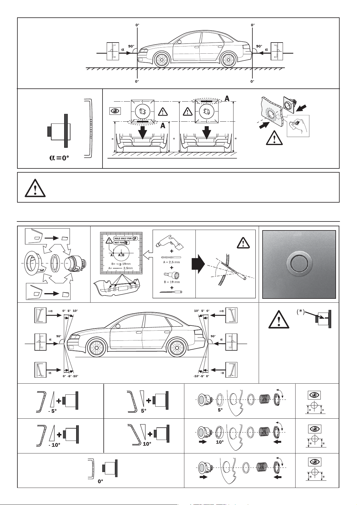
Fig. 6
NOTE: DEGREASE THOROUGHLY
BEFORE APPLYING THE TWO-SIDE
ADHESIVE TAPE
NOTE: TO MAKE SURE OF A CORRECT WORKING, CHECK THAT THE POSITIONING REFERENCE ITEM
(A) IS HORIZONTAL. ONCE THE SENSORS ARE FITTED TO THE BUMPER DO NOT WET OR FORCE
THEM FOR THE NEXT 8 HOURS.
INSTALLATION WITH THE ESH SYSTEM (EXTERNAL SENSOR HOLDER)
Fig. 7
NOTE: TO MAKE
SURE OF A CORRECT
WORKING CHECK
THAT THE POSITIONING
DOWEL (*) IS
FACING SIDEWAYS
16
Page 7
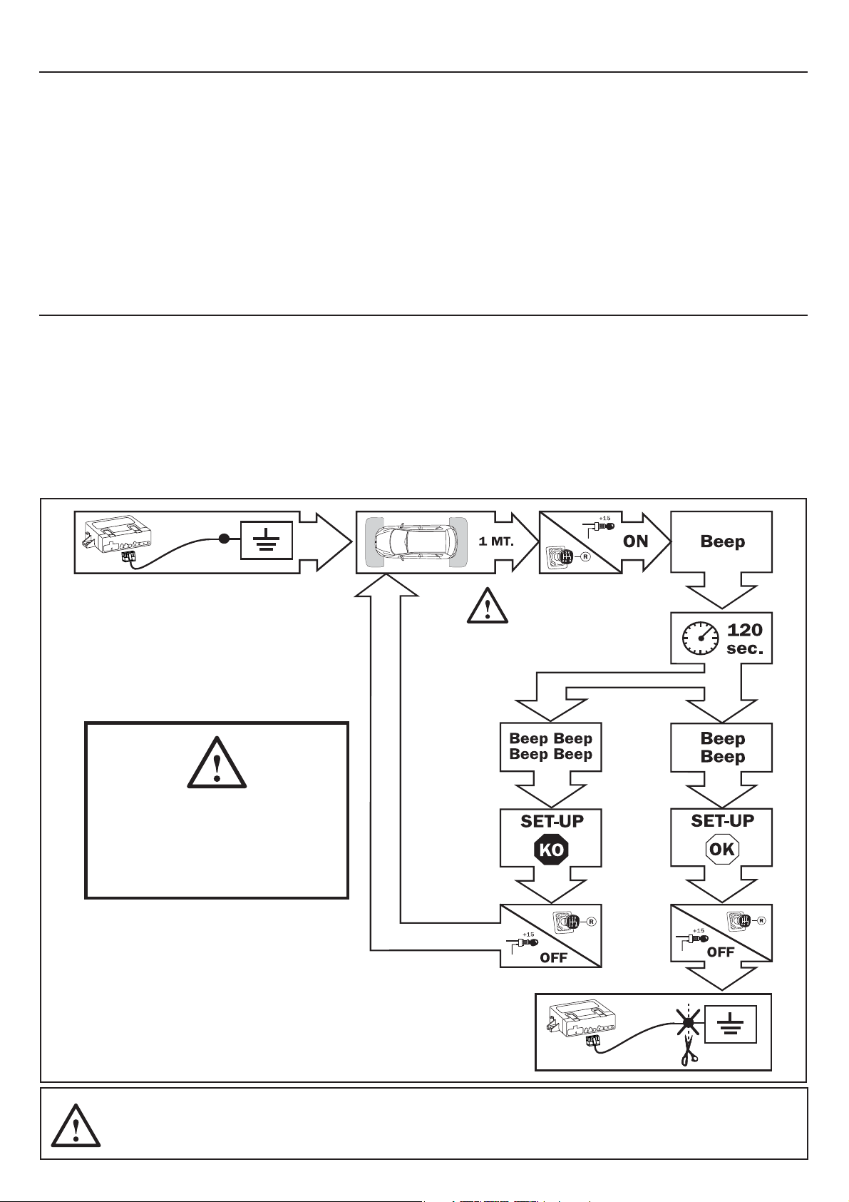
PROGRAMMING
There are two essential functions that ensure the correct working of the product on the vehicle: the speed programming (only for
the front system) and the obstacles masking. The rst sets the speed threshold that automatically enables/disables the parking system. The second one allows to make the parking system consider all xed obstacles (e.g. tow bar) as part of the vehicle and thus it
does not detect them during the parking manoeuvre. If, however, the installation is di erent to what speci ed, the system can still
perform two additional settings: one to reduce performance (to be used only if strictly necessary) and another one that allows to
reduce the detection range of the side capsules (only for very round bumpers or when the position of the side capsules is very close
to the edges of the car). Here are the procedures to apply the 4 settings:
• MASKING THE DETECTION OF OBSTACLES OR JUTTING PARTS
• REDUCING SYSTEM PERFORMANCE
• REDUCING SIDE CAPSULE READING
• RECORDING SPEED (if system used with odometer)
MA
SKING PROCEDURE
The system can exclude xed objects, such as the tow hook or spare wheel (in case of rear application) or protruding parts (front
application) that are always inside the detection area of the sensors and ensure that they will no longer be detected during each
parking manoeuvre. To programme follow these steps:
NOTE: make sure that no objects are around the vehicle. Keep at least 1 m of clearance from any object before launching
this procedure.
1. Unplug the PUSH BUTTON/LED connector from the front control unit, position 3 (see scheme at page 13 - Fig.1).
2. Connect temporarily the RED/BLUE wire to negative (GND) with the system o .
3. Connect the RED and GREY wire to +12V, the control unit generates 1 acute beep. After a maximum of 120 sec., another 2 beeps
are emitted if programming was successful or 4 beeps in case of failure.
4. Disconnect the RED and GREY wire from +12V and disconnect the RED/BLUE wire from the negative.
5. Re-plug the PUSH BUTTON/LED connector and then test the system.
RED/DARK BLUE
ATTENTION!
MASKING MUST BE DONE
WITH RUNNING ENGINE
Fig. 8
RED/
DARK BLUE
NOTE: IN THE MAJORITY OF CASES TO LAUNCH THE MASKING PROCESS IT IS SUFFCIENT, AFTER CONNECTING THE RED/BLUE WIRE
TO THE NEGATIVE, TO TURN THE IGNITION ON (+15 V) WITH THE REVERSE GEAR ENGAGED. HOWEVER PAY ATTENTION TO CARS
WHERE THE REVERSE GEAR IS ACTIVATED WITH A DIFFERENT TIMING FROM IGNITION IN THIS CASE, IT IS NECESSARY TO CONNECT
THE RED AND GREY WIRES TO +12V.
17
Page 8
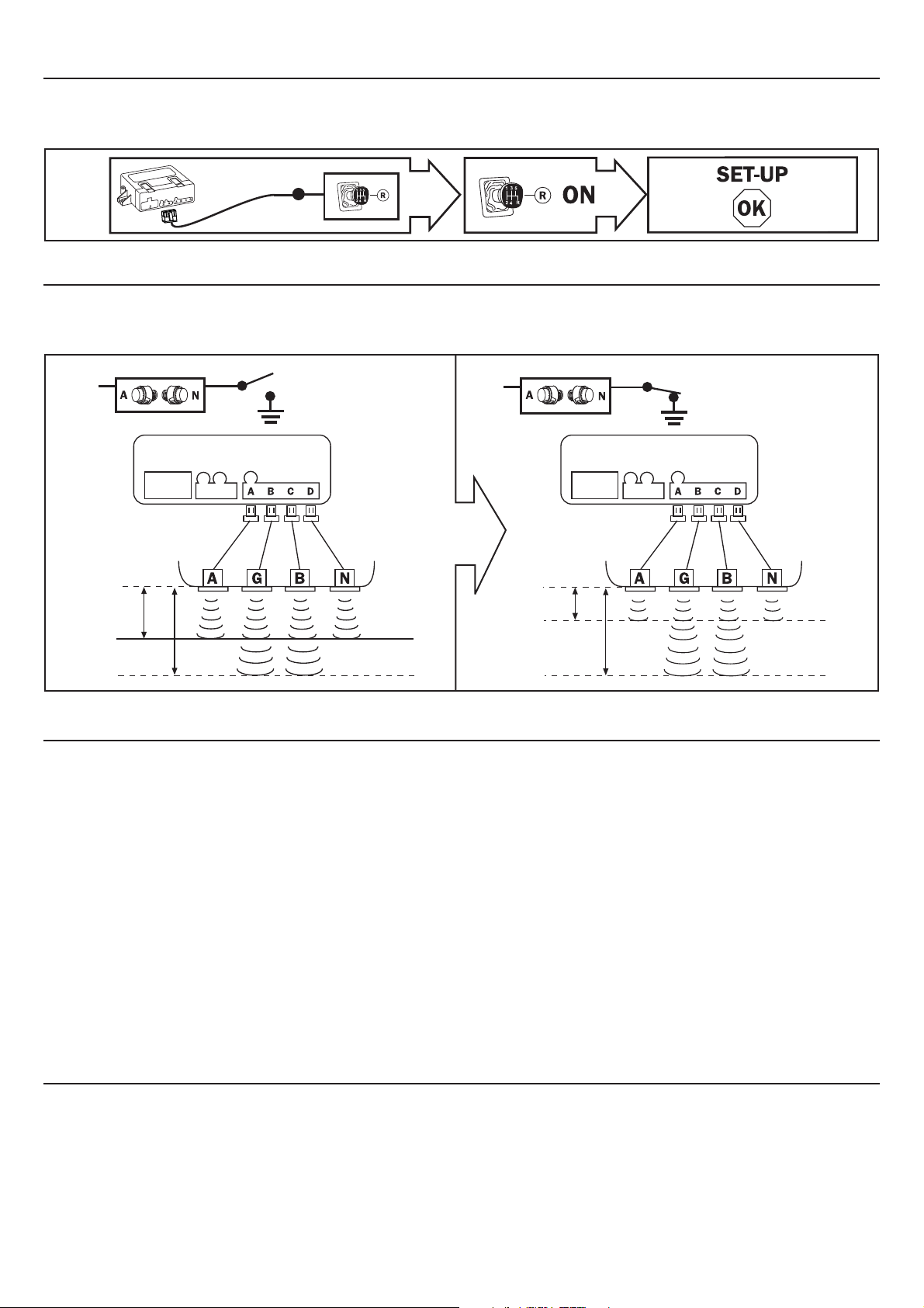
REDUCING THE SYSTEM’S PERFORMANCE
This function is to be used only if strictly necessary. It drastically cuts system performance which prevents false detections, in case
the product is installed di erently from what prescribed in this document. To set this function, simply connect the RED/BLUE wire
to the reverse gear positive.
RED/DARK BLUE
Fig. 9
REDUCING THE SIDE SENSORS DETECTION
The range of detection of the side capsules can be reduced in case it wouldn’t allow the driver correctly evaluate the distance from
an obstacle, during a tricky parking manoeuvre. To activate this function, simply connect the YELLOW wire to the negative (GND).
This function is recommended in the majority of the applications.
YELLOW
STANDARD
OFFSET
Fig. 10a Fig. 10b
OFFSET
REDUCE
YELLOW
SYSTEM MODES FOR THE FRONT APPLICATION
The parking system for a front bumper application can be used in 3 di erent ways, depending on how it is set-up via the PDC/Alarm
programmer; two of these modes entail recording the speed measured by connecting the GREEN/BLACK wire to the vehicle’s odometer. With all 3 modes, the front parking system activates as soon as the ignition is turned ON and/or the reverse gear is
engaged. The di erences between these functional modes are:
1) Manual system (factory setting):
The system switches o 20 seconds after having disengaged the reverse gear or, alternatively, by pressing the push button/LED,
even with the reverse gear engaged. The system can be reactivated by selecting again the reverse gear or pressing the push button
/LED.
2) System switching o according to the speed (set-up via PDC programmer of function 43 ON):
The system switches o a few seconds after having exceeded the speed Programmed and reactivates again after having engaged
the reverse gear or pressed the push button/LED, if the vehicle’s speed is under the programmed threshold.
3) Switching o and activation on speed (programming with the PDC programmer of functions 43 and 44 ON):
This setting is not connected to the reverse gear. The parking system activates the very moment the instrument panel is turned on
and deactivates a few seconds after having overtaken the programmed speed.
The system automatically reactivates by slowing down the vehicle, under the programmed speed threshold.
TEMPORARY DISENGAGEMENT: In order to temporarily exclude the automatic system reactivation, press the push button/LED. The system
will resume all its functions by pressing again the push button/LED or automatically the next time the ignition is turned on.
RECORDING THE SPEED THRESHOLD
Follow the procedure described below to adjust the system’s deactivation speed threshold:
1. Start the engine and check that the push button/LED is on.
2. Press the push button/LED once and check that it turns o .
3. Press the push button/LED and hold it down for about 30 seconds. Wait until a series of beeps (6) is generated to advise that
the system has entered the speed threshold adjusting mode.
4. Keep driving the vehicle (it is advisable not to overtake 30Km/h). When the chosen speed is reached, press the push button/
LED to have it recorded.
To check if the system has recorded the right speed value, exceed this speed and check that, after a few seconds, the system turns
itself o (push button/LED OFF); then slow down under the speed threshold and check that a few seconds later the system turns
back on (push button/LED ON).
18
Page 9
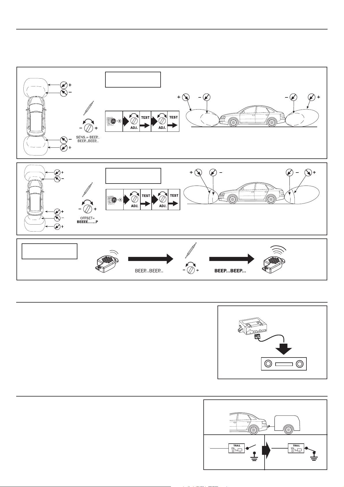
CALIBRATION
With the three trimmers on the front of the control unit it is possible to nely tune the system’s performance on the basis of the
customer’s requirements or on the shape of the bumper. The trimmers manage the three following functions:
SENSITIVITY - Adjusting the capsules’ reading sensitivity. Therefore it is possible to modify the protection space.
OFFSET - Danger zone “continuous sound” detection distance.
VOLUME - To manage the loudspeaker’s volume.
SENSITIVITY
Fig.11
OFFSET
VOLUME
ADDITIONAL FUNCTIONS
CAR STEREO MUTE – This function allows to automatically mute the car stero du-
ring a parking manoeuvre and, more generally, at the very activation of the parking system to prevent the sound of the stereo from covering the signalling of a
possible obstacle.
To activate this function, connect the PURPLE wire to the car stereo MUTE setting.
NOTE FOR FRONT APPLICATION: If the parking system is programmed to work with the
vehicle’s odometer, it is advisable NOT to use the mute function.
SYSTEM’S CUT-OFF FOR TRAILER CONNECTION TO THE VEHICLE
Fig.14
Fig.12
Fig.13
Car radio mute
PURPLE
CAR RADIO
TRAILER – this rear application dedicated function allows to automatically
deactivate the control unit when the ground line has been taken from the
trailer’s electric connector.
19
Trailer disabling
Disabling OFF Disabling ON
BROWN
Fig.15
BROWN
Page 10
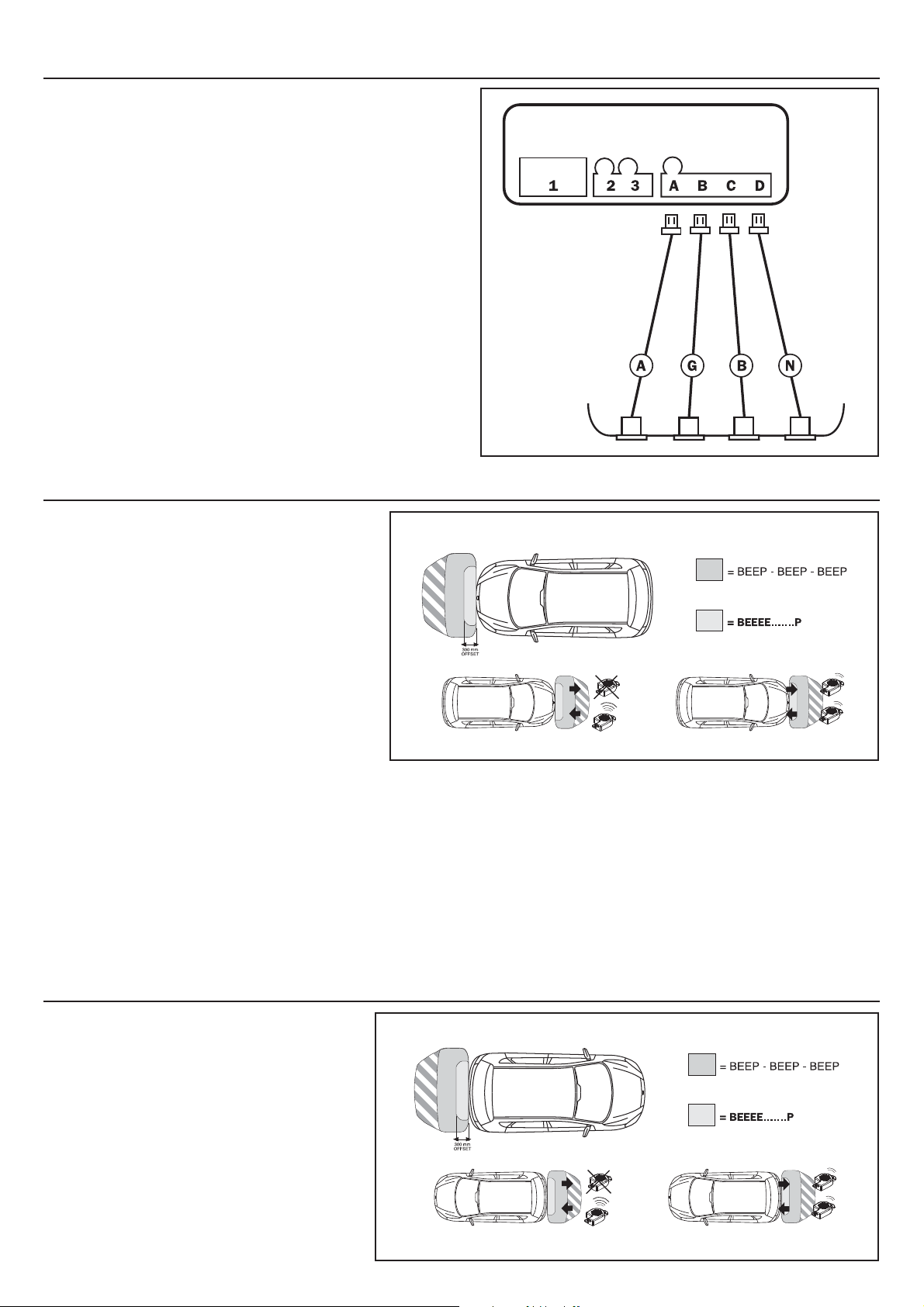
DIAGNOSTICS
While the system is working it constantly keeps a self-diagnosis
operation running in order to warn the user - through speci c
acoustic signals - if one or more sensors are not correctly working.
If failures occur,one or more acoustic signals are generated at every activation:
• long beep with di erent tone + N° 1 short beep =
Sensor A fault;
• long beep with di erent tone + N°2 short beeps =
Sensor G fault;
• long beep with di erent tone + N° 3 short beeps =
Sensor B fault;
• long beep with di erent tone + N°4 short beeps =
Sensor N fault;
After the system has provided the above mentioned information,
it cuts-o the faulty sensors and then starts working as usual.
If the failure occurs during a parking manoeuvre, the control unit
stops its standard detection/signalling of an obstacle and generates the diagnostic signal described above.
HOW TO USE THE FRONT SYSTEM
Fig.16
LEFT SIDE
OF BUMPER
RIGHT SIDE
OF BUMPER
The acoustic signal is intermittent when an obstacle is detected, and grows in frequency as the vehicle gets closer to the obstacle itself, starting from
around 110 cm, it becomes a continuous sound
when the car is at about 30 cm to it (Fig. 17).
Signalling frequency decreases down to about 8090 cm when moving away from the obstacle and
it stops if the vehicle moves further away from the
obstacle itself.
The system automatically activates when the ingnition is switched on and when reverse gear is engaged whereas turning o depends on what was
programmed during the installation; the following
3 modes are possible:
Fig.17
1) System with timer or manual:
The system deactivates 20 seconds after the reverse gear has been deselected and reactivates each time the reverse gear is engaged or the push button/LED is pressed.
2) System’s cut-o for overtaking the speed threshold:
The system deactivates when the programmed speed is overtaken and reactivates each time the reverse gear is selected or the
push button/LED is pressed.
3) System’s switch-o for overtaking the speed threshold and automatic reactivation as speed slows down within the limit:
The system deactivates when the programmed speed is overtaken and reactivates each time the vehicle slows down the same
speed threshold, allowing to constantly protect the car during the low speed manoeuvres.
The system can be disabled with the push button/LED until the next time the ignition has started or by pressing the push button/
LED.
HOW TO USE THE REAR SYSTEM
When reverse gear is engaged, one BEEP signals
the system’s activation.
The acoustic signal is intermittent when an obstacle is detected, and grows in frequency as the
vehicle gets closer to the obstacle itself, starting
from around 150 cm, it becomes a continuous
sound when the car is at about 30 cm to it (Fig. 18).
Signalling frequency decreases down to about 8090 cm when moving away from the obstacle and
it stops if the vehicle moves further away from the
obstacle itself.
Fig.18
20
 Loading...