

Page 1
USER’S MANUAL
Thermal Receipt Printer
T-40
Page 2

T-40 User’s Manual
1
Contents
1 Introduction ....................................................................................................................... 1
1.1 Outline .......................................................................................................................... 1
1.2 Features ....................................................................................................................... 1
2 Specification ...................................................................................................................... 2
2.1 Technical specification .................................................................................................. 2
2.2 Cutter parameters ......................................................................................................... 3
2.3 Paper specification ....................................................................................................... 3
2.3.1 Parameters of continuous paper ................................................................................ 3
2.3.2 Parameters of marked paper ..................................................................................... 4
3 Appearance and components ............................................................................................ 5
3.1 Appearance and modules .............................................................................................. 5
3.2 LED and buzzer ............................................................................................................ 7
4 Installation ......................................................................................................................... 8
4.1 Unpacking .................................................................................................................... 8
4.2 Printer installation ......................................................................................................... 8
4.3 Power and communication interface .............................................................................. 9
4.3.1 Power connection ..................................................................................................... 9
4.3.2 Interface connection ................................................................................................. 9
4.3.3 USB interface connection .......................................................................................... 9
4.3.4 Cash drawer connection ........................................................................................... 9
4.4 Paper roll installation .................................................................................................. 10
4.4.1 Paper type confirmation .......................................................................................... 10
4.4.2 Install/replace paper roll ......................................................................................... 10
4.5 Paper near end position adjustment ............................................................................ 12
4.6 Power-on and self-test ................................................................................................ 13
4.6.1 Power-on ................................................................................................................ 13
4.6.2 Print self-test page ................................................................................................. 13
4.7 Hexadecimal dumping function .................................................................................... 14
5 Routine maintenance ....................................................................................................... 15
5.1 Cleaning the print head and the platen roller ............................................................... 15
Page 3

T-40 User’s Manual
2
5.2 Cleaning the mark sensor ............................................................................................ 15
5.3 Clearing the jammed paper and the cutter error ........................................................... 15
6 Interface signal ................................................................................................................ 16
6.1 Serial interface ........................................................................................................... 16
6.2 Parallel interface ......................................................................................................... 16
6.3 USB interface ............................................................................................................. 18
6.4 Ethernet interface ....................................................................................................... 18
6.5 Double communication interface .................................................................................. 19
6.6 Power interface definition ............................................................................................ 20
6.7 Cash drawer interface signal definition ........................................................................ 20
7 Troubleshooting .............................................................................................................. 22
7.1 Printer doesn’t work .................................................................................................... 22
7.2 Error LED and buzzer alarm ........................................................................................ 22
7.3 Problems during printing ............................................................................................. 22
8 Power management ......................................................................................................... 23
9 DUMP mode ..................................................................................................................... 24
Appendix Button configuration ........................................................................................... 25
Page 4

T-40 User’s Manual
1
1 Introduction
1.1 Outline
T-40 is developed for high-end thermal receipt printing market, which is widely used.T-40 can
be connected with other devices via serial, parallel, USB, Bluetooth, Ethernet and WLAN. It
provides drivers for operation systems such as Windows 2000 / XP /Server 2003 / Vista /
Server200 / Win7 / Win8 /Win8.1 / Win10/Server 2012, POSReady2009 / POSReady7, Linux,
Mac and UPOS middleware.
Note: Windows and Linux drivers support 64-bit operation system.
1.2 Features
Ø Low noise, high printing speed;
Ø Support continuous paper, marked paper;
Ø Support paper saving, water mark, upside-down, two-color printing, etc.;
Ø Compact size, can output paper from the front or the top according to users’ different
demands;
Ø Rich interfaces: USB(fix on board), expandable serial / parallel / Ethernet / Bluetooth / WIFI /
serial + Ethernet interface;
Page 5
T-40 User’s Manual
2
2 Specification
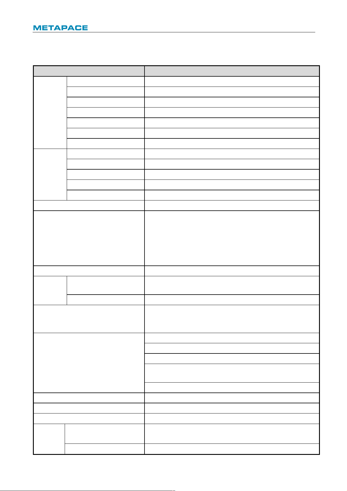
2.1 Technical specification
Item
Parameter
Printing
Print method
Direct thermal line printing
Resolution
203 × 203 DPI; 203 × 180 DPI
Paper width
57.5/80/82.5 mm
Print width
Max.80 mm
Print speed
Max.250 mm/s
Flash LOGO
Max. 1M bytes
Command buffer area
64K bytes, 4K bytes or 45 bytes
Interface
USB
USB 2.0 (full speed)
Serial interface
RS-232C
Parallel interface
IEEE1284
Ethernet interface
10/100BASE-T
Cash drawer
Can select to controlling 1~ 2 cash drawers
Memory
RAM: 2 MB, Flash: 4 MB
Printer status detection
Paper end sensor/ black mark sensor;
Paper near end sensor;
Cover position sensor;
Paper presence sensor
Print head temperature sensor;
Printer voltage detection
Cut mode
Full cut, partial cut
Barcode
1D
UPC-A, UPC-E, CODE 39, CODE 93, CODE 128, EAN8, EAN13,
ITF, CODABAR
2D
PDF417, QR, Maxicode
Fonts
Font A: 12 × 24
Font B: 9 × 17
Kanji font A: 24 × 24
Character set
95 Alphanumeric
14 types of international characters
128 x 68 code page
Optional: Traditional Chinese, Simplified Chinese
(GB2312/18030), Japanese, Korean, English, HK
User-defined font (95) & code page
Character enlargement
All characters can be enlarged 1-6 times horizontally and vertically
Character rotation
Rotation printing in four directions (0°, 90°, 180°, 270°)
Command
ESC/POS compatible
Paper
Paper type
Thermal continuous paper
Thermal marked paper
Paper roll OD
Max. 83 mm
Page 6
T-40 User’s Manual
3
Paper thickness
0.06 mm~0.10 mm thermal paper
Power
supply
Input
100-240V AC, 50-60 Hz
Output
24V ± 5% DC, average current 2A
External or not
External power adapter
Human-machine
interface
Power switch
Support
Button
Support
LED
Support, including POWER LED and ERROR LED
Buzzer
Support, 24V buzzer
Reliability
Lifetime of print head
≥150Km (standard test sample with 12.5% duty ratio)
Lifetime of cutter
2,000,000 cuts (standard test condition)
MCBF
70,000,000 lines
MTBF
360,000 hours (main control board)
Operation temperature and humidity
5°C~45°C, 20%~ 90% RH(40°C)
Storage temperature and humidity
-40°C~ 60°C, 10%~90% RH(40°C)
Overall dimensions
127mm(L)*127mm(W )*134mm(H)
Functions
Saving paper
Support
Button configuration
Support (configure the printer without computer)
Right-up-side printing
Support
Water mark printing
Support
Gray scale printing
Support
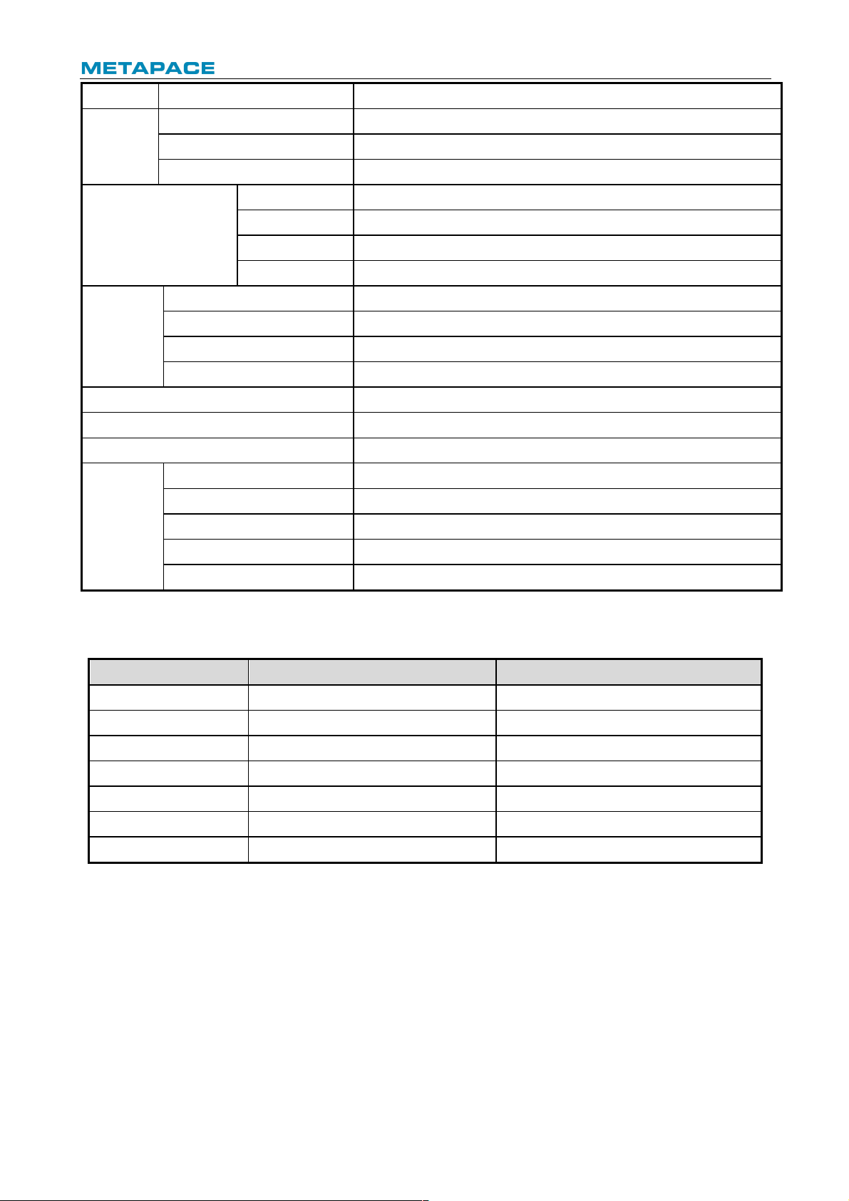
Table 2.1-1 Technical specifications
2.2 Cutter parameters
Item
Parameter
Remarks
Cutting method
Sliding blade
Cutting time
500 ms
The time of one cut
Cutting interval
3 s
20 cuts/minute (Max.)
Applicable paper types
0.06 mm~0.10 mm thermal paper
Operation voltage
24V DC
Max. operation current
1.2A
Operation voltage 24V DC
Cutter lifetime
2,000,000 cuts
Standard test condition
Table 2.2-1 Technical parameters of cutter
2.3 Paper specification
2.3.1 Parameters of continuous paper
Ø Paper type: thermal paper
Ø Paper supply mode: paper roll
Ø Paper width: 57.5/80/82.5 mm
Ø Paper thickness: 0.06 mm-0.10 mm
Ø Thermal layer: outward
Ø Paper roll specification: paper roll OD Max ф83 mm, core ID Min. ф12.8 mm
Page 7
T-40 User’s Manual
4
Ø Paper recommended:
Paper model
Manufacturer
600-3.1
APPLETON Papers Inc
KLS_46_e
KANZAN Spezialpapiere GmbH
FD210
OJI Paper CO., LTD.
Table 2.3-1 Recommended thermal paper model
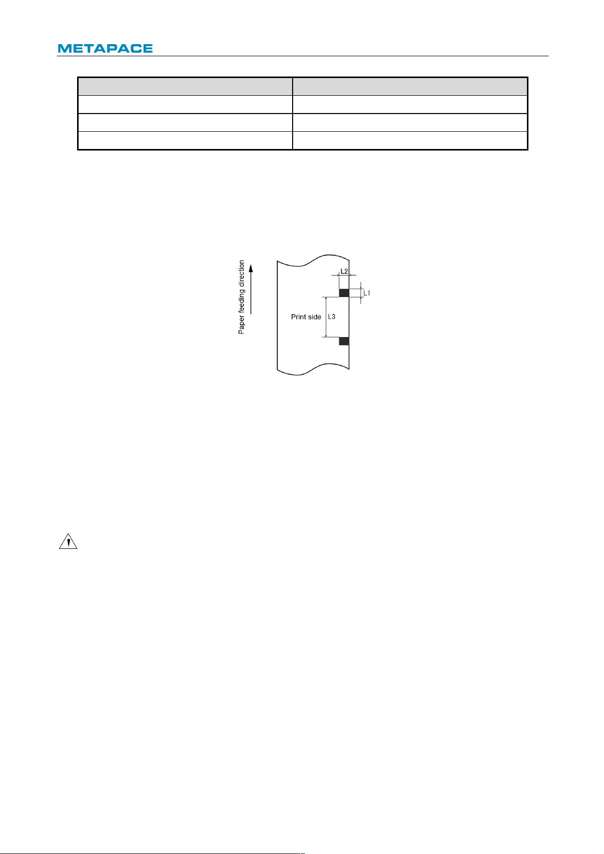
2.3.2 Parameters of marked paper
T-40 can support marked paper printing and set the cutting and initial printing position
accurately. The marked paper not only should meet the specifications of thermal paper roll, but
also should meet the following requirements:
Ø L1 mark height: 3 mm≤ L1≤13 mm
Ø L2 mark length: L2≥8 mm
Ø L3 distance between two marks: 30 mm≤L3<450 mm
Ø Thermal side mark sensor position: reserved the left/middle/right positions
Ø Non-thermal side mark sensor position: the middle/left/right position is selectable
Ø Reflectivity: The reflectivity of the black mark must be no more than 15% while the reflectivity
of the paper itself should exceed 85%. There should be no image between the two marks,
such as the advertisement, etc.
Caution:
² Please use the recommended paper or its equivalents. Using the paper of low quality might
affect the print quality and shorten the lifetime of print head;
² Do not stick paper onto the core shaft;
² If the paper is contaminated by chemical or oil, it may discolor or lose heat sensitivity at the
polluted spot, which will affect the print affect;
² Do not rub the paper surface with hard objects, otherwise it may affect the print affect;
² When the environment temperature goes up to 70℃, paper will discolor. Thus don not use or
store paper under high temperature, high humidity and strong light conditions.
² The mark is measured during printing and paper feeding. If the mark height value detected
by the sensor is bigger than the default value (default setting is 13mm), the printer will alarm
paper end.
Page 8
T-40 User’s Manual
5
3 Appearance and components
3.1 Appearance and modules
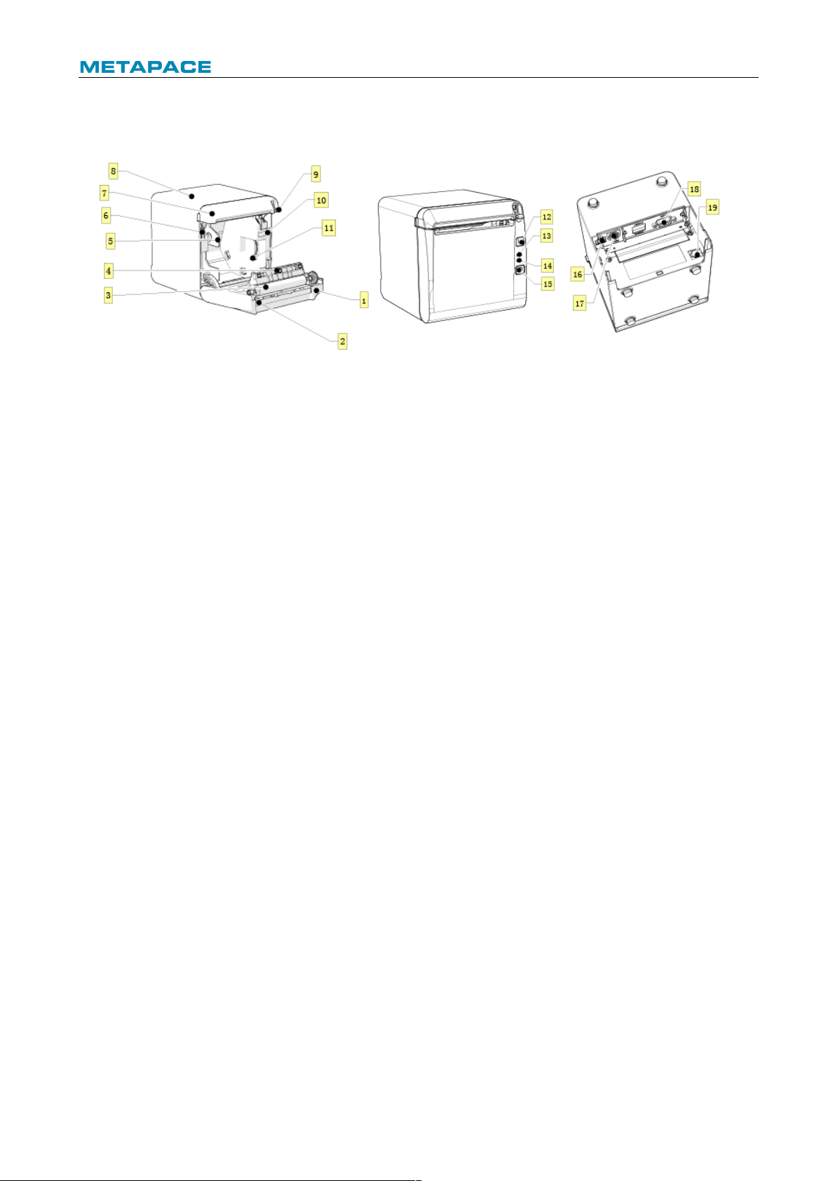
Fig. 3.1-1 Schematic drawing of appearance and modules
1— Top cover
2— Cutter
3— Platen roller
4— Paper end sensor
5— Paper guide
6— Micro switch
7— Cutter cover
8— Middle cover
9— Cover open spanner
10—Paper cabinet
11—Paper near end sensor
12—FEED button
13—ERROR LED
14—POWER LED
15—POWER button
16—USB
17—Power interface
18—Communication interface
19—Cash drawer interface
Button and component function:
a FEED button (12)
Ø Feed paper:
Printer will feed paper when the feed button is pressed down under normal condition. To
feed paper continuously, keep pressing the button.
Ø Print configuration sample:
Pressing down the feed button while turning on the power, the printer will print out the
configuration sample, which includes print width, print speed, etc.
Ø Enter button configuration mode:
Press down the feed button while turning on the power, the printer will print out the
configuration sample, and enter pause status (error LED flashes) after cutting paper.
Keep pressing the feed button at this time, the printer will enter button configuration mode.
Ø Press the button to clear the cutter error:
Press the button for a short time when a cutter error occurs, the printer will try to clear the
cutter error automatically.
b Error LED (13)
Indicate printer status. Under normal status, the error LED is off. Under error status (e.g.
paper end, etc.), the error LED flashes.
c Power LED (14)
Indicate printer power status (ON/OFF).
d Power button (15)
Page 9

T-40 User’s Manual
6
Press the button to connect power; press the button for a long time to disconnect the power.
e Top cover status detection sensor (14)
Detect the printer cover status (open/closed).
f Paper presence sensor (12)
Detect the paper presence / absence status when continuous paper is used; detect the
paper marks when marked paper is used.
g Spanner for adjusting paper near end sensor(7)
Detect the paper roll status. Fast flashing of error LED indicates that the paper will be used
out soon and the user should replace the paper roll in time. Printer will work normally until
paper is used out.
h Paper guide (5)
Adjust the position of paper guide in the cabinet to adapt to different paper widths between
58/80mm. When the paper guide is removed, the printer can adapt to 82.5mm paper width.
Page 10
T-40 User’s Manual
7
3.2 LED and buzzer
1) Functions of LED
LED name
Status
Description
Power LED
(green)
Always on
Printer power is on.
Off
Printer power is off.
Error LED
(red)
Off
Printer is in normal status.
Flash
Printer is in error status or paper near end status.
Buzzer
Beep
Printer is in error status.
Table 3.2-1 Functions of LED
2) Error type indicated by LED & buzzer
Error Type
Error LED
Buzzer
Print head is overheating
Cycle flash 6 times
Cycle beep 6 times
Printer voltage is abnormal
Cycle flash 5 times
Cycle beep 5 times
Cutter error
Cycle flash 4 times
Cycle beep 4 times
Print head lift-up
Cycle flash 3 times
Cycle beep 3 times
Paper end
Cycle flash 2 times
Cycle beep 2 times
Paper near end
Cycle flash slowly
No beep
Cannot find mark or mark calibration error
Cycle flash slowly
No beep
Table 3.2-2 LED and indication information
Caution:
² The temperature of the print head is detected by a thermal resistor. If the print head is
overheating, the protective circuit will shut off the power automatically and force the printer
to stop printing; the temperature of print head when printing is stopped is 65℃.
Page 11
T-40 User’s Manual
8
4 Installation
4.1 Unpacking
Check whether all items, which are listed on the packing list, are present and in a good
condition. If any item is damaged or missing, please contact your dealer or the manufacturer.
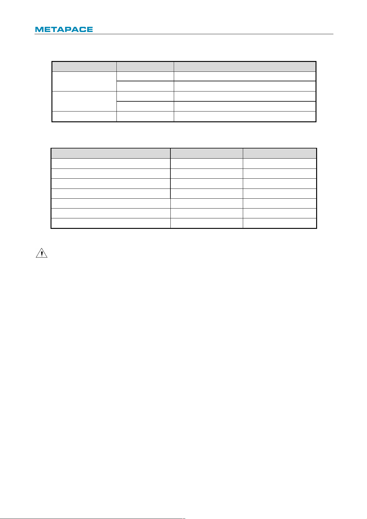
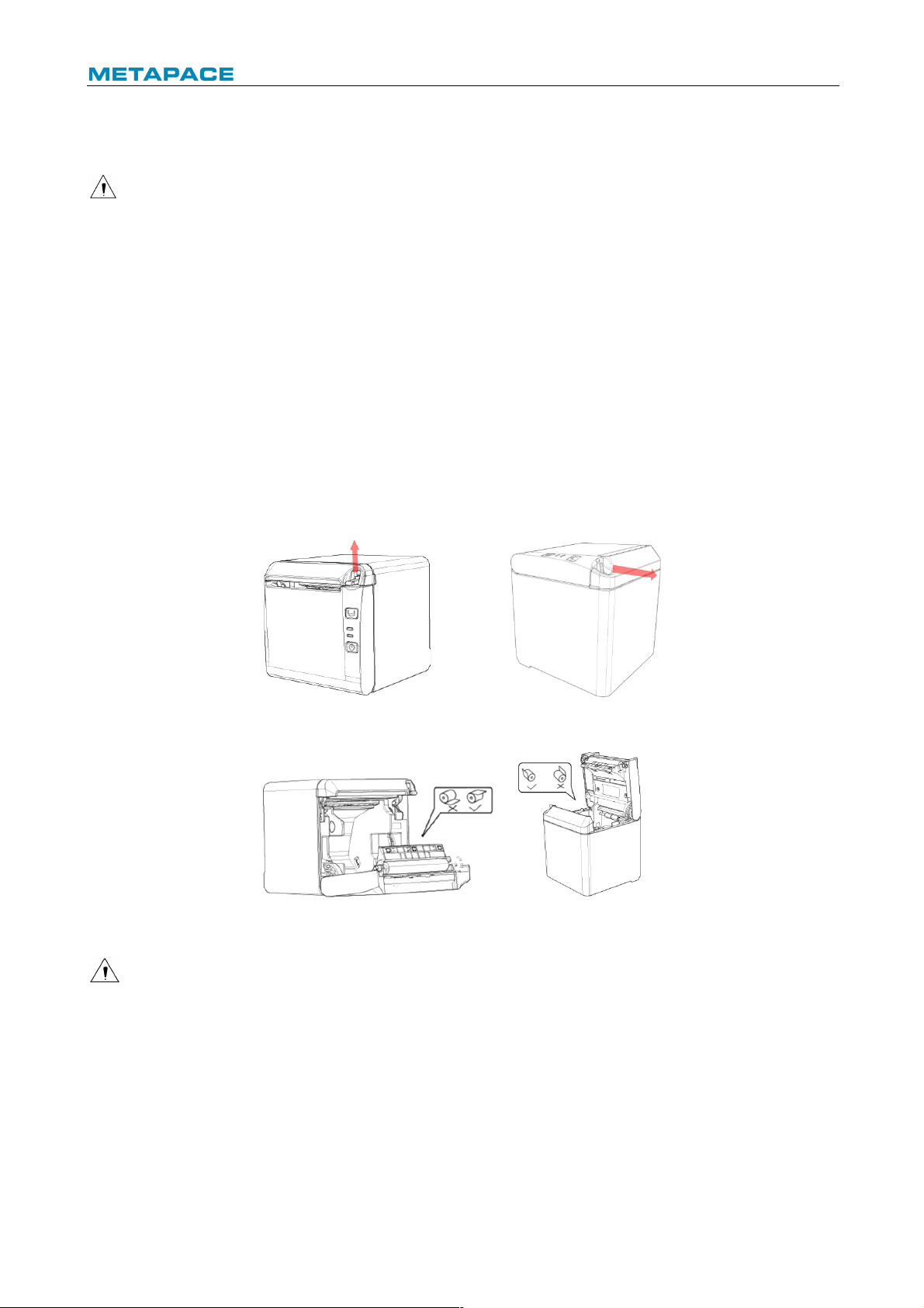
4.2 Printer installation
1) T-40 supports two working methods: out put the paper from the front or the top when place
the printer horizontally on the table. When the printer is placed horizontally on the table,
the incline installation angle should not exceed 5°, otherwise the paper near end sensor
will not work normally.
Fig. 4.2-1 Horizontally on the table (paper output from the front)
Fig. 4.2-2Horizontally on the table (paper output from the top)
2) Keep the printer far away from water source;
3) Do not place the printer in the place exposed to vibration and impact;
4) The printer power must be safely grounded;
5) It is recommended to keep proper space in order to guarantee the reliability and
operational convenience of the printer during operation and maintenance.
Fig.4.2-3 Printer maintenance and operation space
Page 12
T-40 User’s Manual
9
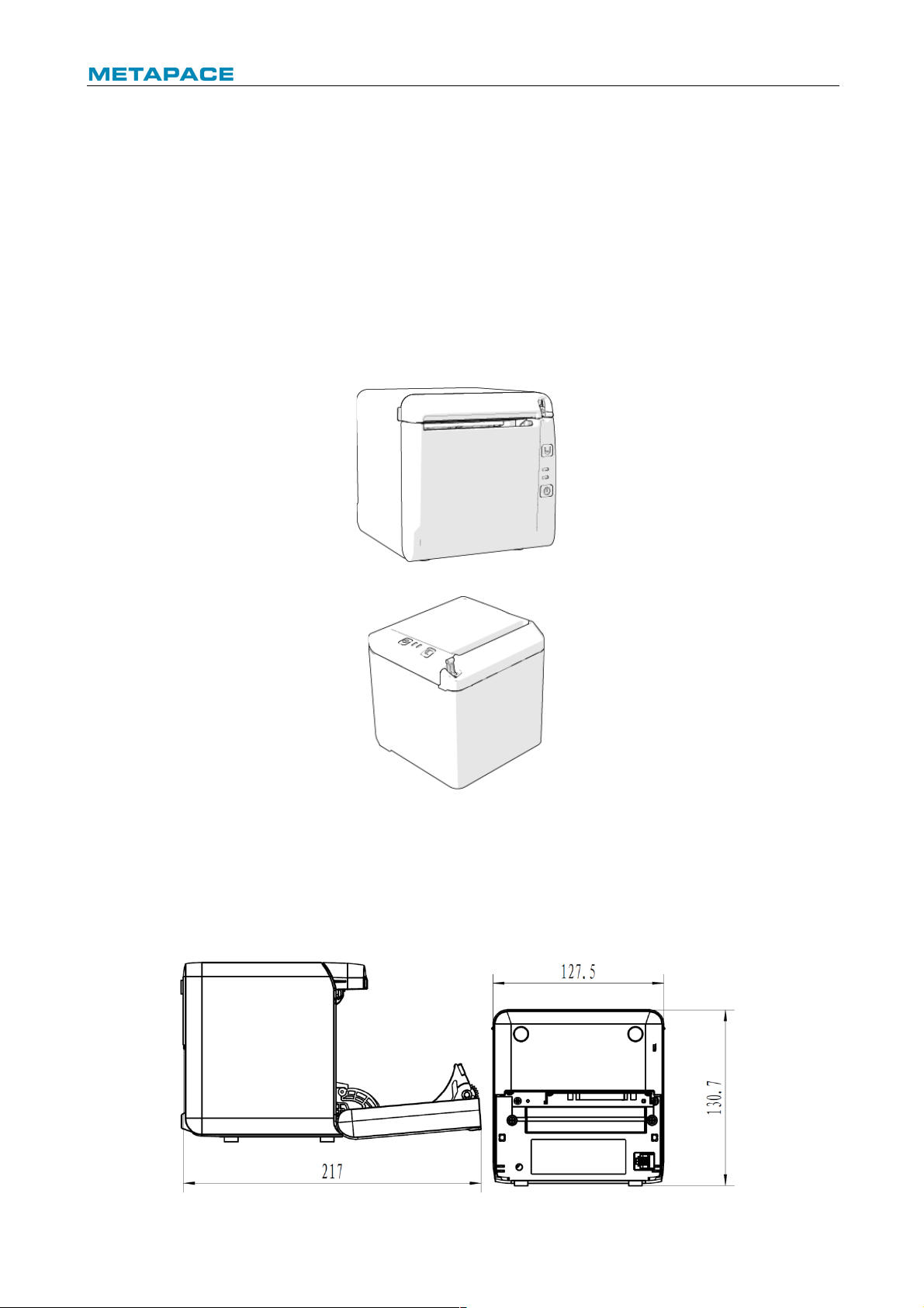
4.3 Power and communication interface
4.3.1 Power connection
1) Ensure that the power switch is turned off;
2) Insert the power plug into the corresponding socket on the back of the printer.
Caution:
² When the printer is not in use for a long period of time, disconnect the power cord from the
printer.
4.3.2 Interface connection
1) Ensure that the power switch is turned off;
2) Plug the connector into corresponding port and fix it with screw or spring as shown in the
figure;
3) Connect the other end of cable to the host.
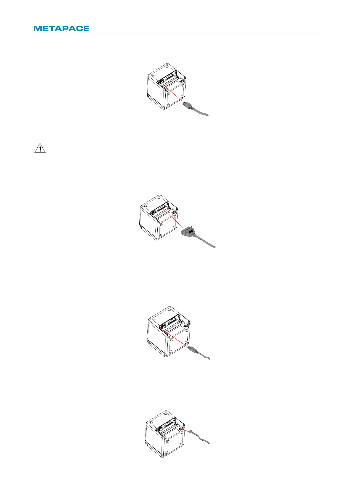
4.3.3 USB interface connection
1) Ensure that the power switch is turned off;
2) Plug the USB cable into corresponding interface in place as shown in the figure;
3) Connect the other end of USB cable to the host.
4.3.4 Cash drawer connection
Page 13
T-40 User’s Manual
10
1) Ensure that the power switch is turned off;
2) Plug the cash drawer cable into the cash drawer interface which locates at the back of
printer.
Caution:
² The cash drawer interface is used to connect the cash drawer only (cannot connect with
phone wire, etc.).
4.4 Paper roll installation
4.4.1 Paper type confirmation
After connecting the power cord and interface cable, confirm paper type after media installation
before printing.
4.4.2 Install/replace paper roll
1) Turn off the printer;
2) Push the spanner in the direction shown in the Fig. to open the top cover;
3) Place the paper roll into the printer;
4) Close the top cover.
Fig. 4.4-1 Schematic drawing of paper roll installation/replacement
Fig. 4.4-2 Schematic drawing of paper roll installation/replacement
Caution:
² Adjust the paper guide according to the paper specification: install the paper guide at the
position of 57.5 for 57.5 wide paper roll; install the paper guide at the position of 80 for 80
wide paper roll; and remove the paper guide for 82.5 wide paper roll. Pay attention that the
winding direction of paper roll should meet printer requirements. Remove the end in
operation hole firstly when disassemble the paper guides, and install the end in operation
hole firstly when install the paper guides;
Page 14

T-40 User’s Manual
11
Fig. 4.4-3 Failure model
² Ensure that the paper roll is tightly wound; otherwise paper jam or other failure may occur
(eg. Fig.4-3 Failure model );
² Paper roll should be placed stably in the paper cabinet without incline, or the printing will be
affected.
Fig.4.4-4 Position of 57.5 Fig. 4.4-5 Position of 80
Fig. 4.4-5 Operation hole
Page 15

T-40 User’s Manual
12
4.5 Paper near end position adjustment
Fig. 4.5-1 Schematic drawing of paper near end position adjustment (output paper from the front)
Fig. 4.5-2 Schematic drawing of paper near end position adjustment (output paper from the front)
Page 16

T-40 User’s Manual
13
The following diameter of core shaft of paper roll supported by the printer are as following: OD
of 16.2mm core shaft and OD of 20.8 mm core shaft; adjust the paper near end sensor to adjust
the application method and paper near end alarm function for core shaft with different outer
diameters. There are four positions indicated by the scale marks for paper near end alarm, and
users can rotate the paper near end adjustment spanner to make the indication line locate at
different position, which change the paper near end alarm functions under different application
conditions. The position 1 and 2 are for the application that output paper from the top, position
1 is for 16.2 mm core shaft of paper roll and position 2 is for 20.8 mm core shaft of paper roll.
The position 3 and 4 are for the application that output paper from the front, position 3 is for
20.8 mm core shaft of paper roll and position 4 is for 16.2 mm core shaft of paper roll.
Fig. 4.5-3 core shaft of paper roll
4.6 Power-on and self-test
4.6.1 Power-on
1) Ensure that the printer is connected to power;
2) Turn on the power switch to power on the printer.
4.6.2 Print self-test page
1) Ensure that the printer is connected to power, and that paper roll is installed;
2) Ensure that the power LED is off and the printer is under power-off condition.
3) Press the feed button while turning on the printer power, and then release the button. The
printer will print out configuration information and prompt characters “Press and Release
FEED key to print characters” and “Press and Hold FEED key to config the printer”. Then
the printer enters pause status, and the error LED flashes;
Page 17

T-40 User’s Manual
14
4) Pressing the feed button momentarily, the printer will print out a character test sample, and
the printing of self-test page is completed. Pressing the feed button for a long time, the
printer will enter button configuration mode.
4.7 Hexadecimal dumping function
After entering Hexadecimal dumping mode, the printer will print out the data transmitted from
the host computer in hexadecimal and their corresponding ASCII characters.
The sample printed under Hexadecimal dumping mode is as follows:
Fig. 4.7-1 Print sample under Hexadecimal dumping mode
Using Hexadecimal dumping mode:
1) Entering Hexadecimal dumping mode in the following ways:
a. Open the printer mechanism and turn on the printer while pressing the feed button.
Release the button after the printer alarms (LED flashes and buzzer beeps).
b. Send command “GS ( A”.
2) The printer first prints "Hexadecimal Dump To terminate …..", and then prints the data
transmitted from the host in hexadecimal and their corresponding ASCII characters.
3) Exiting from Hexadecimal dumping mode in the following ways:
a. Turn off the power, and then restart the printer.
b. Press the feed button three times.
Caution:
² If the hexadecimal data has no corresponding ASCII characters, the printer will print ".";
² Under Hexadecimal dumping mode, only commands DLE EOT, DLE ENQ, or DLE DC4 are
valid.
² The data of the last character line can be printed by pressing down the feed button.
Page 18

T-40 User’s Manual
15
5 Routine maintenance
Caution:
² Before starting routine maintenance, ensure that the printer power is turned off.
² Do not use organic solvents like gasoline or acetone.
² When cleaning sensors, do not turn on the printer power until the pure alcohol has
completely evaporated.
² It is recommended that the maintenance cycle should not be longer than one month.
5.1 Cleaning the print head and the platen roller
Follow the steps below to clean the print head and the platen roller:
1) Turn off the printer and open the top cover;
2) If the printing was just finished, please wait for the print head to cool down completely;
3) Wipe off the dust and stains on the surface of print head and platen roller with alcohol cotton
(it should be wrung out);
4) After the alcohol is completely evaporated, close the top cover.
5.2 Cleaning the mark sensor
When the printer cannot identify the mark effectively, the mark sensor should be cleaned.
The cleaning steps are as follows:
1) Turn off the printer;
2) Press the cover open lever to open the top cover;
3) Wipe off the dust and stains on the surface of the sensor with soft cotton cloth dipped with
pure alcohol (it should be wrung out);
4) Install the sensor cover after the pure alcohol is completely evaporated, then close the top
cover and finish mark sensor cleaning.
5.3 Clearing the jammed paper and the cutter error
Steps for clearing jammed paper and cutter error are as follows:
Method 1:
1) Turn off the printer power and turn the spanner to open the top cover;
2) Clear the jammed paper, and then close the top cover;
3) Turn on the printer power again, and then the cutter can be reset automatically.
Method 2:
1) Turn off the printer power, disassemble the cutter cover in the direction shown in the figure,
and turn the spanner to open the top cover;;
2) Clear the jammed paper, close the paper cabinet and turn on the printer power again, and
then the cutter can be reset automatically.
3) Install the cutter cover.
Page 19
T-40 User’s Manual
16
6 Interface signal
6.1 Serial interface
The serial interface of the printer is compatible with RS-232 standard, and its interface socket
is D-SUB25 socket.
Pin
Signal
Signal definition
Function 1 FG — House ground
2
TXD
Output
Data output
3
RXD
Input
Data input
5
NC — Not connected
6
DSR
Input
Data device is ready
7
SG — Signal ground
8- 19
NC — Not connected
4,20
DTR
Output
Require to send
21-25
NC — Not connected
Fig. 6.1-1 Serial interface definition
User can query interface setting status via printing configuration sample. The default settings of
serial interface are as follows:
Baud rate: 115200bps; Data bits: 8; Parity: none; Stop bit: 1; Handshake: DTR/DSR.
6.2 Parallel interface
The parallel interface can work in IEEE 1284 compatible mode or nibble mode. The interface is
36PIN socket.
Interface definition:
Pin No.
Signal source
Signal definition
1
H
nStrobe
2 H Data 0 (Least Significant Bit)
3
H
Data 1
4
H
Data 2
5
H
Data 3
6
H
Data 4
7
H
Data 5
8
H
Data 6
9 H Data 7 (Most Significant Bit)
10
P
nAck
11
P
Busy
12
P
Perror
13
P
Select
14
H
nAutoFd
15
Not defined
16
Logic Gnd
17
Chassis Gnd
18
P
Peripheral Logic High
19
Signal Ground (nStrobe)
20
Signal Ground (Data 1)
Page 20

T-40 User’s Manual
17
21
Signal Ground (Data 2)
22
Signal Ground (Data 3)
23
Signal Ground (Data 4)
24
Signal Ground (Data 5)
25
Signal Ground (Data 6)
26
Signal Ground (Data 7)
27
Signal Ground (Data 8)
28 Signal Ground (PError, Select, and nAck)
29 Signal Ground (Busy and nFault)
30
Signal Ground (nAutoFd, nSelctIn, and nInit)
31
H
nInit
32
P
nFault
33
Not defined
34
Not defined
35
Not defined
36
H
nSelectIn
36
H
nSelectIn
² H stands for the host and P stands for the printer;
² The letter “n” in front of signal name indicates that the low level is effective;
² In data transmission, the host should not ignore “Busy” signal; otherwise print data may be
missing;
² If the host cannot provide all the signal lines listed in the table above, the communication
may fail;
² Parallel interface signal adopts TTL level; the rise and fall time of the signal from the host
must be controlled within 0.5s when it is used;
² For the interface, the signal line should use twisted pair with feeder line end, with the
feeder line end connected to signal ground;
² The parallel interface connecting wire should be as short as possible on condition that it
meets the use condition.
Page 21

T-40 User’s Manual
18
6.3 USB interface
1) Parameters
Data transmission: Support USB 2.0 full speed protocol.
Connector (Printer end): USB B type socket. Support USB HUB.
2) Interface signal definition and function
Pin No.
Signal name
Description
1
VBUS
Power
2
DATA-
Data minus
3
DATA+
Data plus
4
GND
Ground
Table 6.3-1 USB interface definition
3) Interface connector
Fig. 6.2-1 USB interface connector
4) Mode
USB interface can work under API mode and Windriver mode. API mode is the manufacturer
self-defined mode, and the user needs to install the USB driver provided by the manufacturer.
Windriver mode is also called class mode, it is no need to install drivers and the user can use
Microsoft's generic driver. The factory setting of printer is API mode, the user needs to adjust it
to class mode if the printer is going to work under a Linux system.
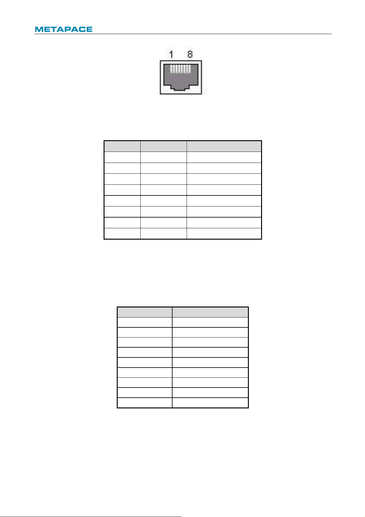
6.4 Ethernet interface
1) Interface features
Ø Support 10/100 BASE-T communication standard
Ø Compatible with Ethernet II standard frame type
Ø LED shows network connection status and data transmission status
Ø Support 9100 port print
Ø Support status back
Ø Support parameter configuration
Ø Support firmware on-line upgrade
Ø Support printer status query and interface module maintenance based on HTTP
Page 22
T-40 User’s Manual
19
2) Interface signal definition
Fig.6.4-1 Ethernet interface
Interface adopts 10/100 BASE-T standard which complies with IEEE 802.3. The interface
signal is defined as below:
Pin No.
Signal name
Description
1
TX+
Data transmission +
2
TX-
Data transmission -
3
RX+
Data receiving +
4
NC
Not connected
5
NC
Not connected
6
RX-
Data receiving -
7
NC
Not connected
8
NC
Not connected
Table 6.4-1Ethernet interface definition
6.5 Double communication interface
Double communication interface support serial interface and Ethernet interface at the same
time.
1) The serial interface of the printer is compatible with RS-232 standard, and its interface
socket is DSUB-9 socket. Pin definition is as following
PIN No.
Signal definition
PIN1
Not connected
PIN2
RXD
PIN 3
TXD
PIN 4
DTR
PIN 5
SG
PIN6
DSR
PIN 7
RTS
PIN 8
CTS
PIN 9
Not connected
2) Ethernet interface
Details refer to section “6.4 Ethernet interface”.
Page 23
T-40 User’s Manual
20
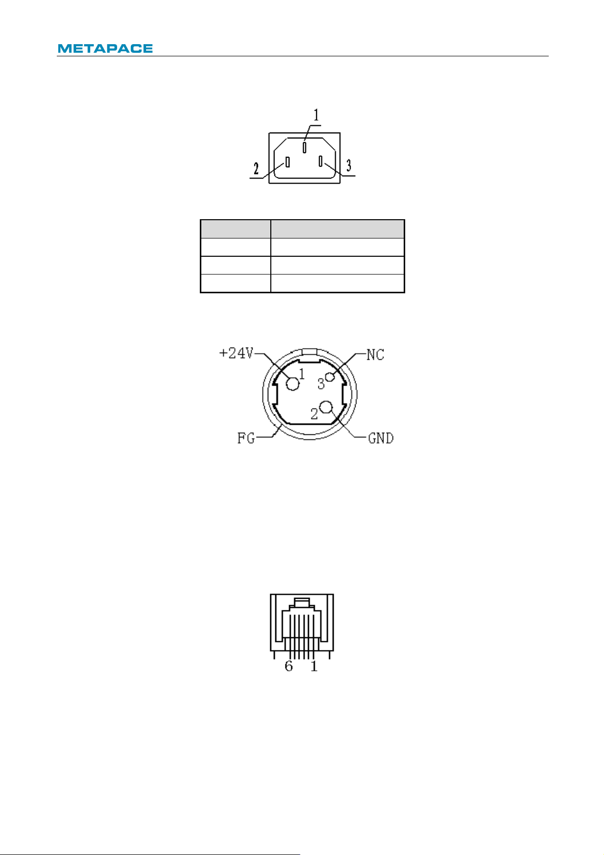
6.6 Power interface definition
1) Power interface signal definition (100-240V AC):
Fig.6.4-1 Schematic drawing of power interface
Pin No.
Signal name
1 E 2 L 3
N
Table 6.6-1 Power interface definition
2) Main control board power interface definition (24V DC):
Fig.6.6-2 Schematic drawing of 24V power interface
6.7 Cash drawer interface signal definition
1) Electrical features
Ø Driving voltage: DC 24 V
Ø Driving current: Max. 1 A
Ø Cash drawer status detection signal: “L” = 0~0.5 V “H” = 3.3 V
2) Cash drawer interface socket uses RJ-11 6P connector
Fig.6.7-1 Schematic drawing of cash drawer interface
Page 24

T-40 User’s Manual
21
3) Interface signal definition
No.
Signal
Functions
1
FG
Frame Ground
2
DRAWER 1
Cash drawer 1 driving signal
3
DRSW
Cash drawer status detection signal
4
VDR
Cash drawer driving power
5
DRAWER 2
Cash drawer 2 driving signal
6
GND
Circuit share ground
Table 6.7-1 Cash drawer interface definition
Caution:
² Do not connect or disconnect communication cable plug when the printer is powered on;
² Communication cable should be far away from strong current;
² Communication cable should adopt shielded cable.
Page 25
T-40 User’s Manual
22
7 Troubleshooting
When the printer has any problem, refer to this chapter for solution.
If the problem still cannot be solved, please contact your local dealer or manufacturer for
assistance.
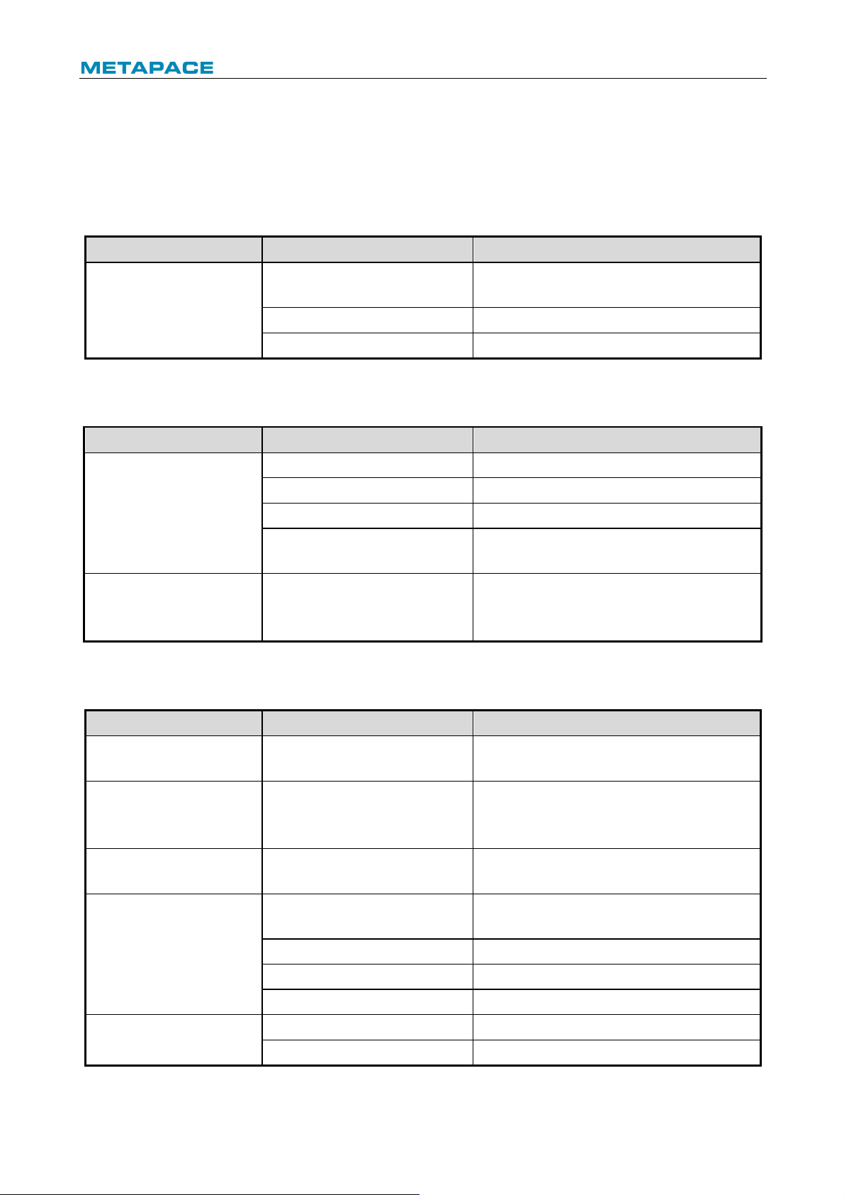
7.1 Printer doesn’t work
Problem
Possible causes
Solution
LED is off and the printer
doesn’t work.
Printer is not connected to
power supply.
Connect the printer to power supply.
Printer power is off.
Turn on the printer power.
Circuit board is damaged.
Contact your local dealer or manufacturer.
Table 7.1-1 Troubleshooting of printer not working
7.2 Error LED and buzzer alarm
Problem
Possible causes
Solution
Error LED flashes or
buzzer beeps.
Paper end
Replace paper roll.
Cutter error
Clear cutter error.
The top cover is open
Close the top cover.
Print head is overheating.
Turn off printer power and wait for the print
head to cool down.
Error LED is always on
and buzzer keeps
beeping.
The printer has serious
malfunction.
Contact your local dealer or the
manufacturer.
Table 7.2-1 Troubleshooting of error LED and buzzer alarm
7.3 Problems during printing
Problem
Possible causes
Solution
Paper cannot be sent out
normally.
Paper jam
Open the top cover, check paper path and
cutter, and clear paper jam.
Printer starts printing but
stops suddenly during
printing.
Paper jam
Open the top cover, check the cutter, and
clear paper jam.
Paper is not cut off.
Paper jam
Open the top cover, check the cutter, and
clear the jammed paper.
Printout is not clear or has
stains.
Paper roll is not installed
correctly.
Check whether the paper roll is installed
correctly or not.
Paper is out of specification.
Use the recommended thermal paper.
Dirty print head or platen roller
Clean the print head or the platen roller.
Print darkness is too low.
Increase the print darkness as needed.
Vertical print content is
missing.
Dirty print head or platen roller
Clean the print head or the platen roller.
Print head error
Contact your local dealer or manufacturer.
Table 7.3-1 Troubleshooting during printing
Page 26

T-40 User’s Manual
23
8 Power management
The power management of T-40 has four operation modes: Off, Standby, Active, Sleep.
Printer will enter standby mode after powering on the printer or completing printing task.
Printer will enter sleep mode if there is no printing task for 2 minutes in standby mode.
Printer will awake automatically and enter active mode when a printing task comes, and will
enter standby mode again after completing the printing task.
Page 27

T-40 User’s Manual
24
9 DUMP mode
There are two methods to enter DUMP mode:
1) Command method: Send 1D 28 41 02 00 00 01
2) Manual mode: Open the top cover, press and hold the FEED button, and turn on the printer
power, then close the paper cabinet and release the button after the ERROR LED flashes.
Pay attention to keep paper in the paper cabinet.
The printer will print out the following contents after the above operation:
“Hexadecimal Dump”
“To terminate hexadecimal dump, press FEED button three times”
The printer already entered the DUMP mode at this moment.
Method to exit from the DUMP mode: continuously press the FEED button for three times, and
the printer will print out the following contents:
"***completed***"
The printer already exited from the DUMP mode at this moment.
Page 28
T-40 User’s Manual
25
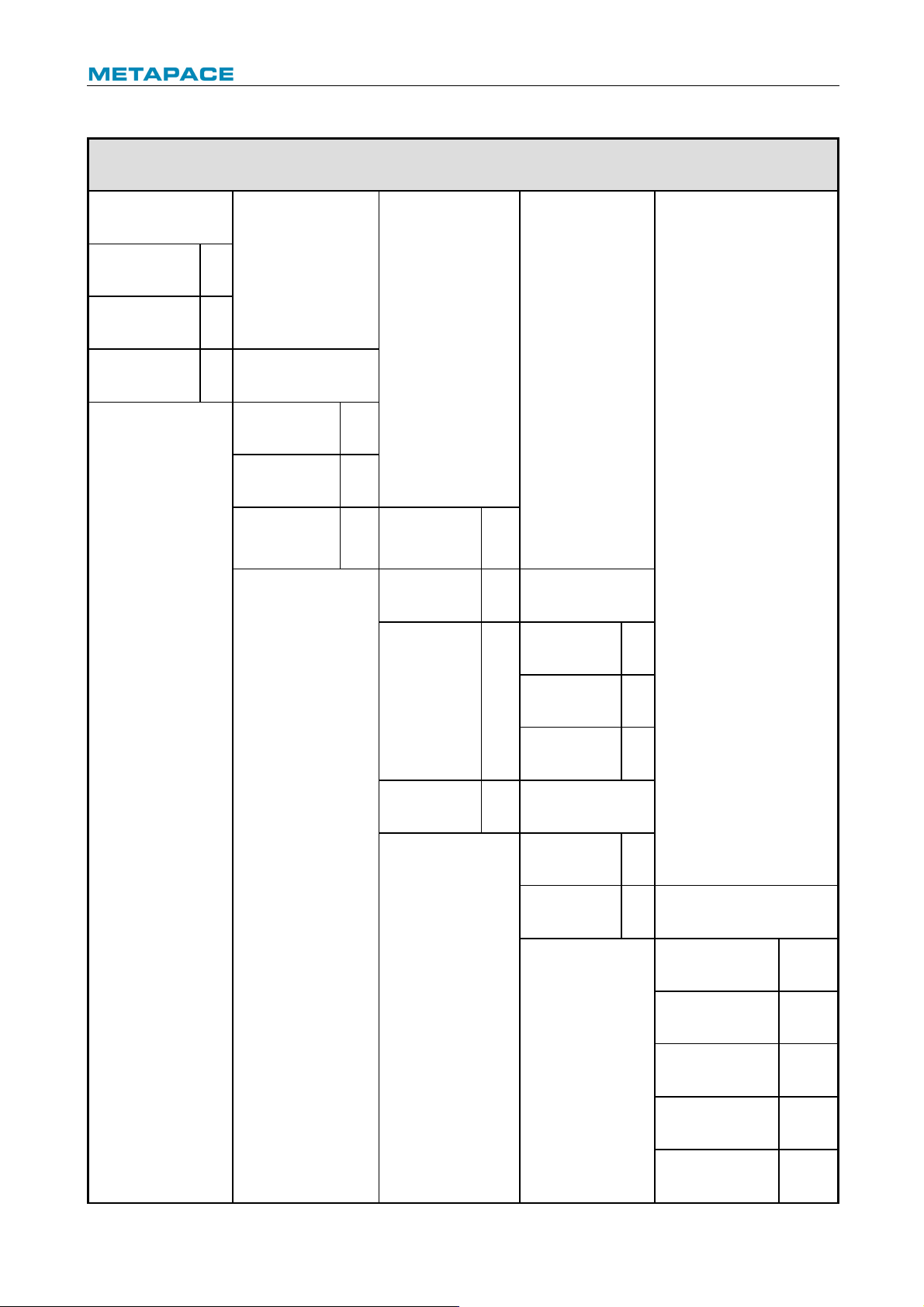
Appendix Button configuration
PARAMETERSETTINGBYFEEDBU
TTON
MAIN ME NU
Exit
->1
Print Self Test
->2
Configuration
->3
CONFIG URATION
Exit W it ho ut
Save
->1
Exit W it h Save
->2
Comm unicat ion
->3
Back To Las t
Me nu
->1
USB Interface
->2
USB mode: API M ODE
Back To Las t
Me nu
->1
Wi nD river Mode
->2
API M ode
->3
Serial In terf ac e
->3
SERIAL I NTER FACE
Back To
Last
->1
Baud Rates
->2
BAUD RATES :115200b ps
Back To Las t Menu
->1
9600bps
->2
19200bps
->3
38400bps
->4
57600bps
->5
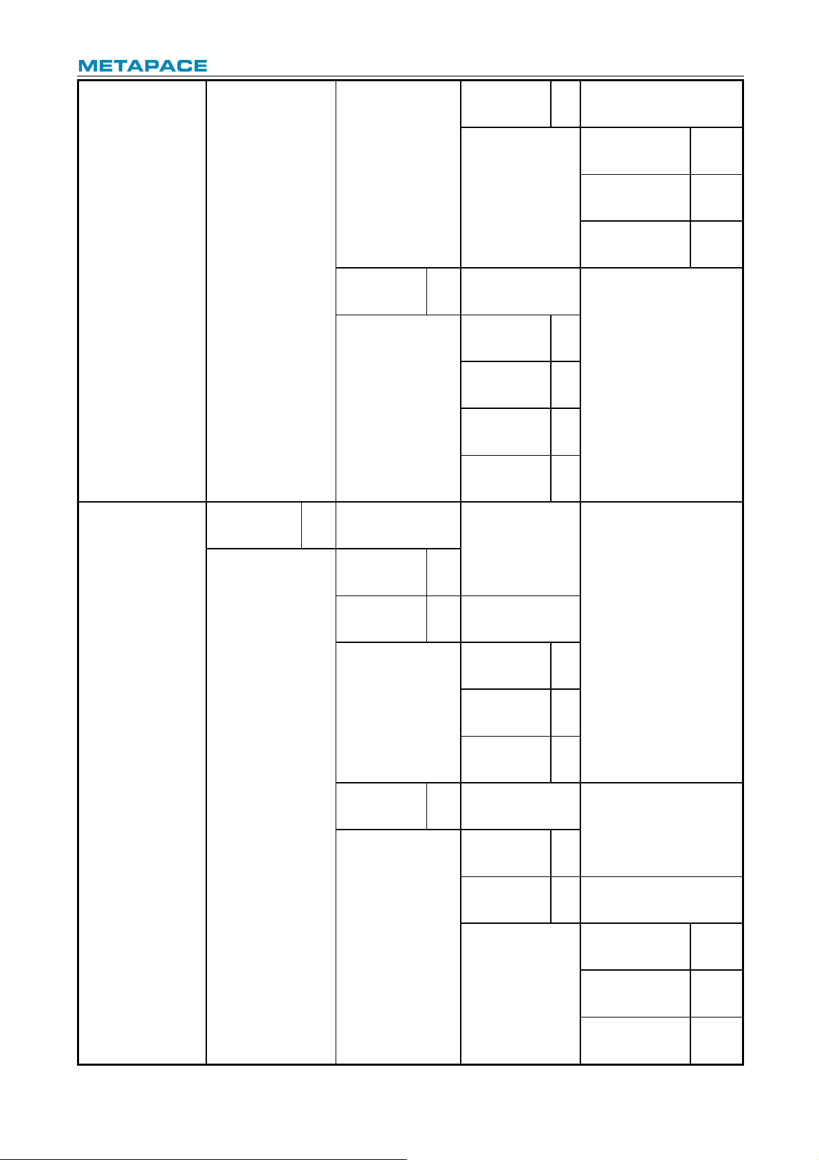
Page 29

T-40 User’s Manual
26
4800bps
->6
2400bps
->7
1200bps
->8
115200bps
->9
Parity
->3
PARI TY: NONE
Back To Las t Menu
->1
None
->2
Odd
->3
Even
->4
Data Bits
->4
DATA BITS: 8 Bits
Back To Las t Menu
->1
7Bits
->2
8Bits
->3
Stop Bi t(s)
->5
STOP BI TS: 1Bi t
Back To Las t Menu
->1
1 Bit
->2
2 Bits
->3
Handshak ing
->6
HANDSHAKING: DTR/ DSR
Back To Las t Menu
->1
DTR/DSR
->2
XON/XOFF
->3
Page 30
T-40 User’s Manual
27
Data Re ce iv e
Error
->7
Data Error Setting: I gnored
Back To Las t Menu
->1
Ignored
->2
Print '?'
->3
Rx Buf f Size
->4
RX BUFFER SIZE:4K
Bytes
Back To Las t
Me nu
->1
4 k Bytes
->2
45 Bytes
->3
64 KBytes
->4
Mech anism
& Hard ware
->4
HARDW ARE
SETTINGS
Back To Las t
Me nu
->1
Ma rk Sensor
->2
MA RK S EN SOR:
Disable
Back To Las t
Me nu
->1
Enable
->2
Disable
->3
Cutter
->3
CUTTER:
Back To Las t
Me nu
->1
Cut Mode
Settings
->2
CUTMODESETTINGS:
Default Cut Mode
Back To Las t Menu
->1
Enable
->2
Disable
->3
Page 31

T-40 User’s Manual
28
Full Cut M ode
->4
Partial Cut Mode
->5
Default Cut Mo de
->6
Auto Cut
Settings
->3
AUTOCUT SETTINGS: Nouse
th is function
Back To Las t Menu
->1
Cut paper when
cover is closed
->2
No cut paper when
Cover is closed
->3
Cut paper when
Po wer on
->4
No cut paper when
Po wer on
->5
Disable
->6
Buzzer
->4
BUZZER: Enabled
Back To Las t
Me nu
->1
Enable
->2 Disable
->3
Print Set ting s
->5
PRINT SETTIN GS
Back To Las t
Me nu
->1
Darkness
Settings
->2
DARKNESS
SETTI NG :
Back To Last
Me nu
->1
Low
->2
Normal
->3
High
->4
Page 32

T-40 User’s Manual
29
Extra High
->5
Paper Roll
Wi dt h
->3
PAPER ROLL
WIDTH: 80. 0 mm
Back To Las t
Me nu
->1
57.5 mm
->2
80.0 mm
->3
82.5 mm
->4
Left Margin
->4
LEFT M AR GI N: 7 mm
Back To Last
Me nu
->1
0 m m
->2
1 m m
->3
3 m m
->4
5 m m
->5
7 m m
->6
9 m m
->7
Right Margin
->5
Right margin: 9 mm
Back To Las t
Me nu
->1
0 m m
->2
1 m m
->3
3 m m
->4
5 m m
->5
7 m m
->6
Page 33

T-40 User’s Manual
30
9 m m
->7
CR Command
->6
CR COMMAND:
Disable
Back To Las t
Me nu
->1
Enable
->2
Disable
->3
Code Page
->7
Code page settings
Back To Las t
Me nu
->1
Print All
Code pages
->2
Select A
Code page
->3
Save Paper
Level
->8
SAVE PAPER LEVEL
Back To Las t
Me nu
->1
Disable
->2
25%
->3
50%
->4
75%
->5
100%
->6
Paper Sens or
Settings
->6
PAPER NEAR
END
Back To Las t
Me nu
->1
Paper Low Alarm
->2
Paper low alarm:
Enable
Back To Las t
Me nu
->1
Enable
->2
Page 34

T-40 User’s Manual
31
Disable
->3
Stop Print W hen
PAPER Low
->3
STOP PRINT W HEN
PAPERLOW: D is able
Back To Las t
Me nu
->1
Enable
->2
Disable
->3
Paper Near End
Sensor
->4
PAPER NEAR E ND
SENSER: Enabled
Back To Las t
Me nu
->1
Enable
->2
Disable
->3
Set Def ault
Config
->7
SET DEFAULT
CONFIG URATION
Back To Las t
Me nu
->1
Set Print er To
Default
->2
FONT A/ FONTB
Settings
->8
Current Fon t: FONT A
Back To Las t
Me nu
->1
Select FONT A
->2
Select FONT B
->3
Select
UD FONT A
->4
Select
UD FONT B
->5
Beep settings
->9
Beep settings:
Disabled
Back To Las t
Me nu
->1
Enable External
Herald
->2
Page 35

T-40 User’s Manual
32
Enable Internal
buzzer
->3
BEEP M OD E
Back To Las t
Me nu
->1
Mo de 1
->2
Mo de 2
->3
Mo de 3
->4
Mo de 4
->5
Mo de 5
->6
All Beep disabled
->4
Test Page
Settings
->10
Testpage up to down
print: Disabled
Back To Las t
Me nu
->1
Enable
->2
Disable
->3
Enter co de,then hold
Button Down
Sensor Test
->4
Sensor Test Mode:
ERROR LED stat e will
change according to
se nsorstate To EX IT ,
hold but ton down at
least 1s ec ond
Print NV Bitmap
->5
Cutter Test
->6 Print Stati st ics
->7
T-40 S TATIS TI CS
CUT
:0
TCUT
:0
LFS
TLFS
Page 36

T-40 User’s Manual
33
ONTIM E
:0
E05Conf igurat io n
->8
E05CONFIGURATION
Reset JK-E04
Config
->1
I
Print Set tings
->2
IP Address:
MAC Address:
Subnet Mask:
GATEWAY:
Print Port:
 Loading...