

Page 1
MULTIMACH MULTIMACH
MANUALE D’USO USER MANUAL
I
GB
Page 2
MONTAGGIO E COLLAUDO PNEUMATICO
ASSEMBLY AND PNEUMATIC TESTING
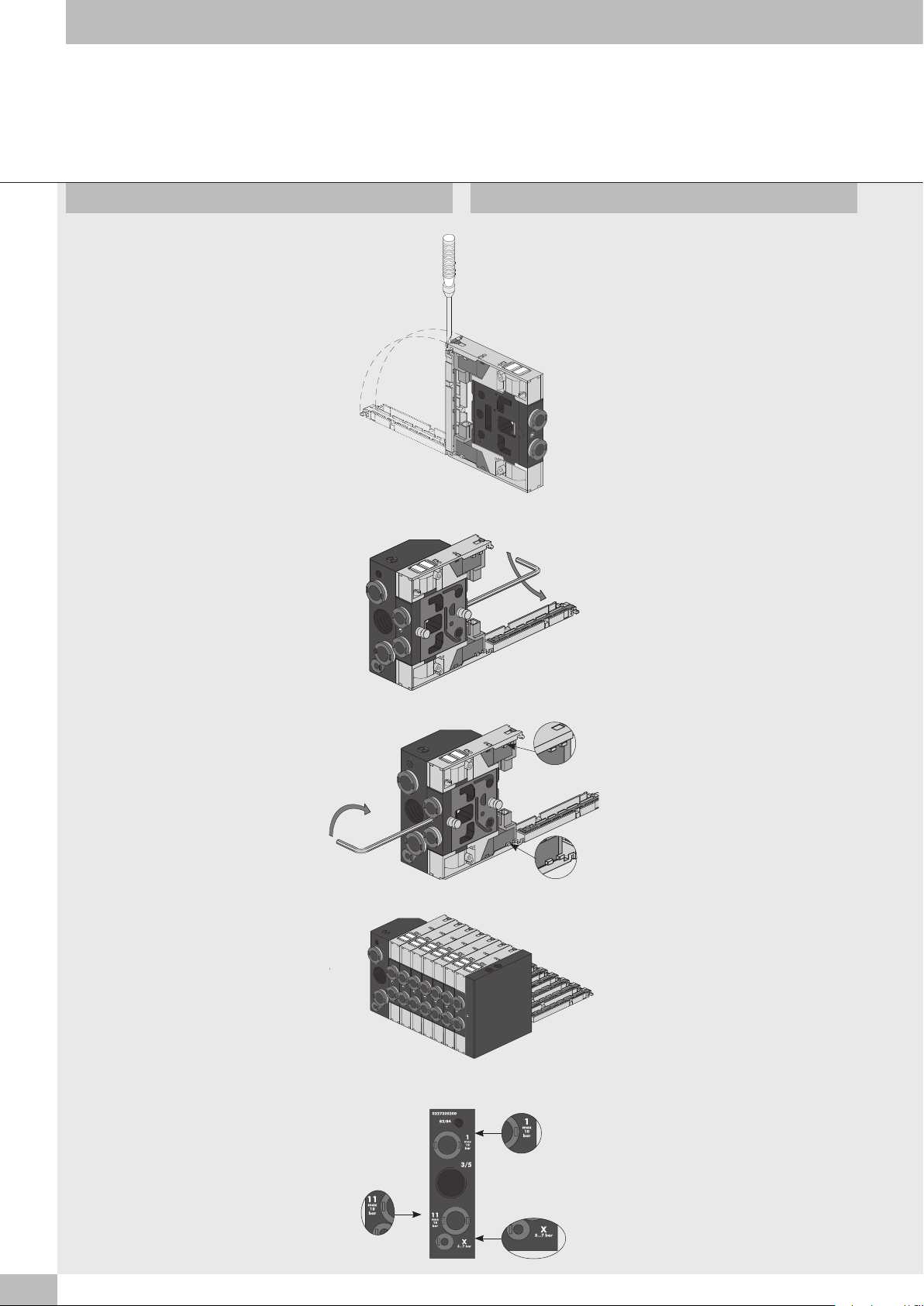
Aprire lo sportello posteriore della valvola,
mediante cacciavite o con le dita, per avere
accesso al sistema di bloccaggio.
Inserire la valvola sul terminale di ingresso.
Serrare il grano di bloccaggio posteriore
con chiave esagonale CH2 con coppia di
serraggio di 2 Nm.
Open the rear door to the valve with a
screwdriver, or your fingers, to access the
blocking system.
Insert the valve on the input terminal.
Tighten the rear locking grub screw with Allen
key CH2 to a torque of 2 Nm.
Serrare il grano di bloccaggio anteriore
con chiave esagonale CH2 con coppia di
serraggio di 2 Nm
Proseguire con la stessa modalità al montaggio
delle altre valvole fino al terminale cieco,
avendo cura di controllare che i dentini A di
ogni piastrina si incastrino nella successiva e
anche nell’apposita sede del terminale cieco.
Dopo il montaggio è necessario effettuare il
collaudo pneumatico dell’isola controllando le
tenute generali. Tappare le bocche di uscita
delle valvole e collegare all’alimentazione le
bocche del terminale di ingresso contrassegnate
dai numeri identificativi 1, 11, X. La pressione
da utilizzare per il collaudo deve essere
compresa tra i due valori limite indicati
sul terminale di ingresso vicino ad ogni
connessione.
Tighten the front locking grub screw with Allen
A
key CH2 to a torque of 2 Nm.
A
Continue in the same way to assemble the
other valves as far as the blind terminal.
Make sure that the small teeth “A” of each
plate engage with the successive ones and
also with the relevant seat in blind terminal.
After fitting it is necessary to perform the
pneumatic test on the island to check general
tightness. Plug the valve output fittings and
connect the terminal input fittings marked with
identification numbers 1, 11, X to the supply.
The pressure used for the test must always be
between the two limit values indicated on the
terminal input close to each connection.
2
Page 3
CABLAGGIO ELETTRICO
ELECTRIC WIRING
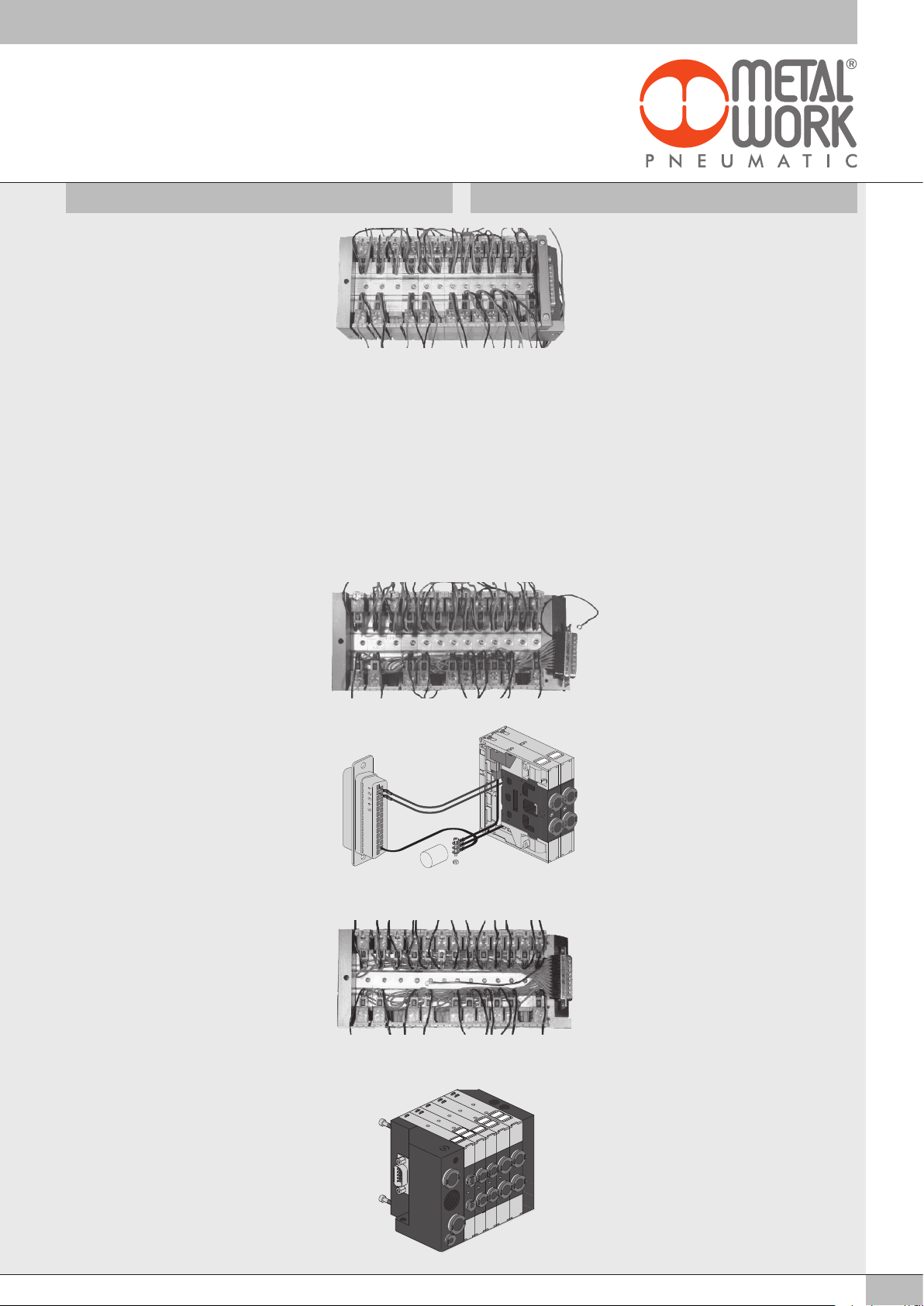
Orientare l’isola in modo che sia accessibile
nella parte posteriore. Inserire i kit
connettore plug-in nei piloti ripiegando i cavi
superiormente ed inferiormente all’isola.
Per isole fino a 6 posizioni utilizzare i kit
connettore plug-in 1-6 valvole codice
0226180399. Per isole da 7 a 12
posizioni utilizzare,fino alla 6a posizione
i kit connettore plug-in 1-6 valvole codice
0226180399, dalla 7ma alla 12ma
posizione i kit connettore plug-in 7-12 valvole
codice 0226180400. Per isole con oltre 12
posizioni utilizzare, fino alla 6a posizione,
i kit connettore plug-in 1-6 valvole codice
0226180399, dalla 7ma alla 12ma posizione
i kit connettore plug-in 7-12 valvole codice
0226180400 e dalla 13ma posizione in poi
i kit connettore plug-in 13-30 valvole codice
0226180401.
Inserire il terminale del cavo prolunga per
comune nella sede del connettore D-sub
contrassegnato dal numero 25/9 secondo il
tipo di connettore.
Inserire i terminali dei cavi rossi degli
elettropiloti inferiori nelle apposite sedi del
connettore D-sub secondo lo schema di
cablaggio a pagina 4 o 5 e convogliare le
anse dei cavi rossi sotto gli elettropiloti
inferiori.
Position the island so that it is accessible
from the rear. Insert the plug-in connector kit
into the electro-pilots by bending the cables
upwards and downwards. For islands with
up to 6 positions, use the 1-6 valve plug-in
connector kit code 0226180399. For islands
with more than 6 positions and up to 12
positions, use the 1-6 valve plug-in connector
kit - code 0226180399 up to the sixth
position and then use the 7-12 valve plug-in
connector kit - code 0226180400 from the
seventh up to the twelfth position. For islands
with more than 12 positions, use the 1-6 valve
plug-in connector kit - code 0226180399 up
to the sixth position, from the seventh up to
the twelfth position use the 7-12 valve plug-in
connector kit - code 0226180400 and then
use the 13-30 valve plug-in connector kit code 0226180401 for the thirteenth position
onwards.
Insert the extension cable terminal as the
common conductor into the D-sub connector
counter-marked by the number 25/9,
according to the connector type.
Insert the terminals of the lower electro-pilot
red cables into the D-sub connector fittings
according to the wiring diagram on page 4 or
5 and lead the loops of the red cables under
the lower electro-pilots.
Inserire i terminali dei cavi rossi degli
elettropiloti superiori nelle apposite sedi
del connettore D-sub secondo lo schema di
cablaggio a pagina 4 o 5 e convogliare le
anse dei cavi rossi sotto gli elettropiloti
superiori.
Montare il supporto connettore sul terminale
mediante le viti M3 ed il connettore sul
supporto mediante le due torrette filettate.
Insert the terminals of the upper electro-pilot
red cables into the D-sub connector fittings
according to the wiring diagram on page 4 or
5 and lead the loops of the red cables under
the upper electro-pilots.
Fit the connector support onto the terminal
using the M3 screws and connect the support
using the two hexagonal lock screw blocks.
3
Page 4
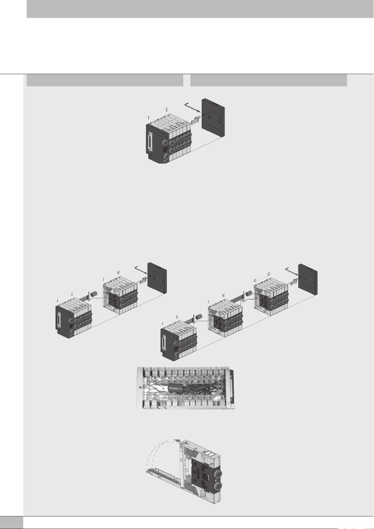
Per isole fino a 6 posizioni
Infilare i terminali ad occhiello dei cavi neri
e della prolunga per comune nella vite e
bloccare con il dado. Avvitare la bussola
isolante sulla vite, quindi posizionarla nella
apposita sede del terminale cieco di chiusura
e bloccarla con il grano M5, facendo
attenzione che nessun contatto tocchi la parte
metallica del terminale o della valvola.
For islands with up to 6 positions
Slide the lug terminals of the black cables and
the common extension terminal onto the screw
and lock down with the nut.
Tighten the insulating bush onto the screw
and then position it in the seat provided in the
blind closing terminal and block it with the
grub screw.
Ensure that no contacts touch the metal part of
the terminal or the valve.
Kit supporto connettore con cuffia di protezione arancio e prolunga
intermedia per comune
- Per isole con oltre 6 posizioni -
Infilare i terminali ad occhiello dei cavi neri, della prolunga per comune
e della prolunga intermedia per comune nelle viti e bloccare con il dado.
Isolare i fili del comune inserendoli nella cuffia di protezione e collocarli
nella posizione più idonea sfruttando lo spazio disponibile.
Avvitare la bussola isolante sulla vite, quindi posizionarla nella apposita
sede del terminale cieco di chiusura e bloccarla con il grano M5,
facendo attenzione che nessun contatto tocchi la parte metallica del
terminale o della valvola.
For connector support kit with orange protection hood and with
intermediate common extension
- For islands with more then 6 positions -
Slide the lug terminals of the black cables, the common extension
terminal and lug terminal of the intermediate common extension onto the
screws and lock down with the nuts. Insulate the common wires by
inserting them into the protection hood and connect them in the most
suitable position, exploiting the space available.
Tighten the insulating bush onto the screw and then position it in the seat
provided in the blind closing terminal and block it with the grub screw.
Ensure that no contacts touch the metal part of the terminal or the valve.
Kit supporto connettore con cuffia di protezione
blu senza prolunga intermedia per comune
- Isole con oltre 6 posizioni -
Infilare i terminali ad occhiello dei cavi neri e
della prolunga per comune nella vite e bloccare
con il dado. Isolare i fili del comune inserendoli
nella cuffia di protezione e collocarli nella
posizione più idonea sfruttando lo spazio
disponibile.
Terminare il montaggio incastrando lo sportello
posteriore nella piastrina superiore.
4
For connector support kit with blue protection
hood and without intermediate common extension
- For islands with more than 6 positions -
Slide the lug terminals of the black cables and
the common extension terminal onto the screw
and lock down with the nut. Insulate the common
wires by inserting them into the protection hood
and connect them in the most suitable position,
exploiting the space available.
End the assembly by engaging the rear door
with the upper plate.
Page 5
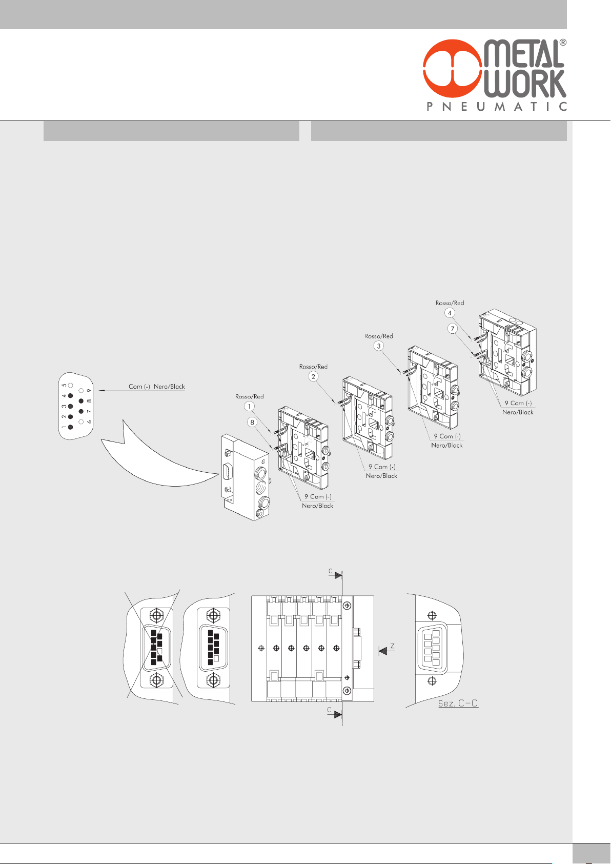
SCHEMA CABLAGGIO E COLLAUDO ELETTRICO DEL CONNETTORE
D-SUB 9 POLI
WIRING DIAGRAM AND ELECTRICAL TESTING FOR THE 9 POLE
D-SUB CONNECTOR
Controllare che il connettore D-sub 9 poli presenti i contatti che
fuoriescono a partire dalla sede n°1 e ad incrementare (1 - 2 - 3 - 4 ...)
e dalla sede n°9 e a decrementare (9 - 8 ...) senza salti di sede (vedi
vista Z).
Controllare che il numero dei contatti maschio sia uguale al numero
degli elettropiloti + 1.
Connettere il polo negativo della tensione 24VDC al contatto 9 del
connettore D-sub a 9 poli.
Verificare che connettendo il polo positivo della tensione 24VDC al
contatto 1 del connettore D-sub a 9 poli si illumini il led dell’elettropilota
1. Ripetere l’operazione per tutti gli elettropiloti connessi (max 8
elettropiloti).
Check that the 9 pole D-sub connector has contacts that protrude starting
from position No. 1 - and increasing (1 - 2 - 3 - 4 ...), and from position
No. 9 and decreasing (9 - 8 ...) without missing any positions (see
view Z).
Check that the number of male contacts is equal to the number of
electro-pilots + 1.
Connect the negative pole of the 24VDC voltage to contact 9 of the 9
pole D-sub connector.
Check that by connecting the positive pole of 24VDC voltage to contact
1 of the 9 pole D-sub connector the LED of the electro-pilot 1 comes on.
Repeat the operation for all the electro-pilots connected (max. 8
electro-pilots).
Cablaggio errato
Incorrect wiring
12345
Vista da Z
View from Z
12345
9876
87
5 posizioni
5 positions
9876
12345
5
Page 6
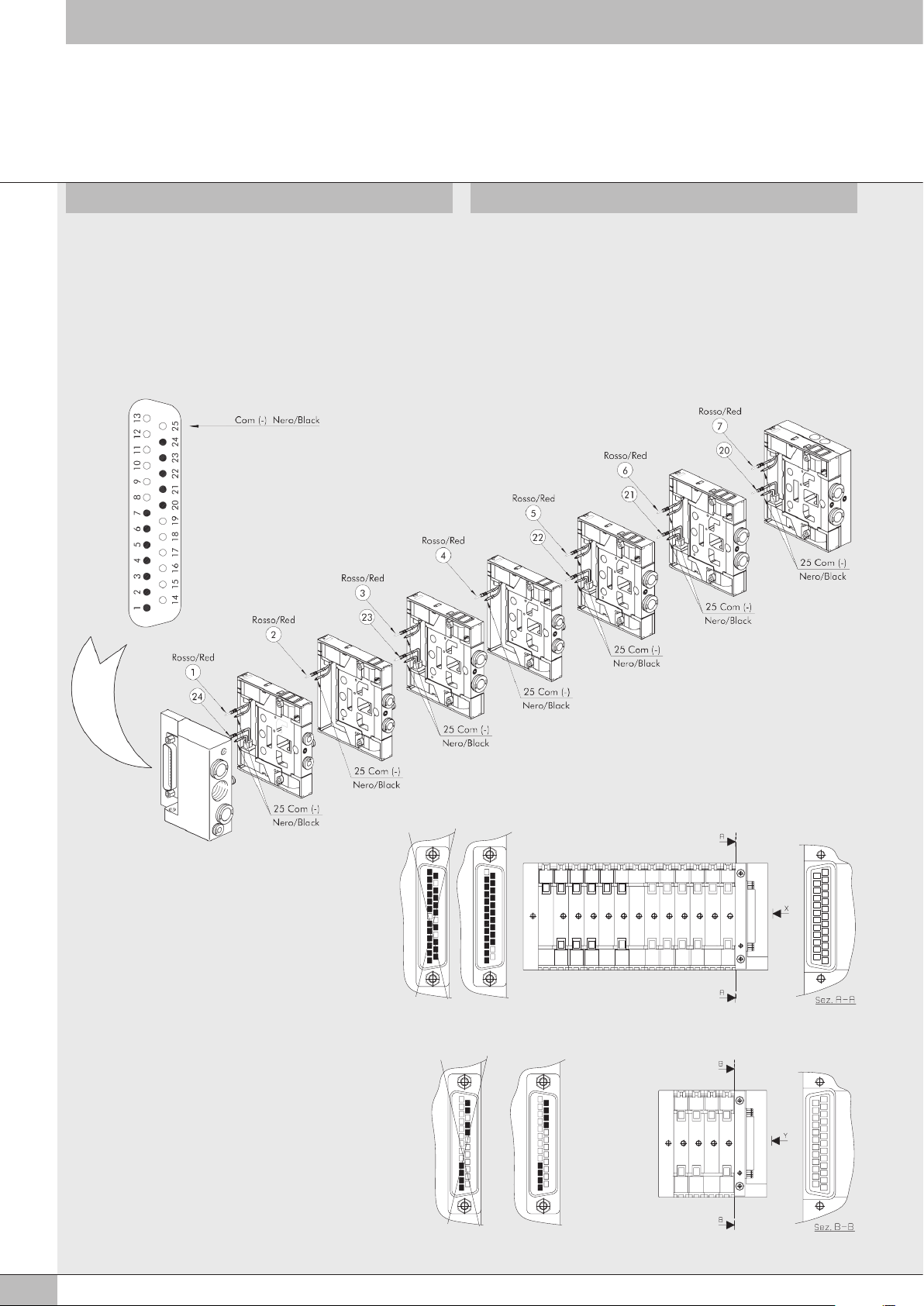
SCHEMA CABLAGGIO E COLLAUDO ELETTRICO DEL CONNETTORE
1210114529
3
8
1
67
14
13
1516 1718 1920 2122 2324 25
12 11 78910
19181716 2120 2322
12243456
2514
243131
242322
........
.......
D-SUB 25 POLI
WIRING DIAGRAM AND ELECTRICAL TESTING FOR THE 25 POLE
D-SUB CONNECTOR
Controllare che il connettore D-sub 25 poli presenti i contatti che
fuoriescono a partire dalla sede n°1 e ad incrementare (1 - 2 - 3 - 4 ...)
e dalla sede n°25 e a decrementare (25 - 24 - 23 - 22 ...) senza salti di
sede (vedi viste X - Y). Controllare che il numero dei contatti maschio sia
uguale al numero degli elettropiloti + 1. Connettere il polo negativo della
tensione 24VDC al contatto 25 del connettore D-sub a 25 poli. Verificare
che connettendo il polo positivo della tensione 24VDC al contatto 1 del
connettore D-sub a 25 poli si illumini il led dell’elettropilota 1. Ripetere
l’operazione per tutti gli elettropiloti connessi (max 24 elettropiloti).
Check that the 25 pole D-sub connector has contacts that protrude
starting from position No. 1 - and increasing (1 - 2 - 3 - 4 ...) and from
position No. 25 and decreasing (25 - 24 - 23 - 22 ...) without missing
any positions (see views X-Y). Check that the number of male contacts
is equal to the number of electro-pilots + 1. Connect the negative pole
of the 24VDC voltage to contact 9 of the 9 pole D-sub connector. Check
that by connecting the positive pole of 24VDC voltage to contact 1 of the
25 pole D-sub connector the LED of the electro-pilot 1 comes on. Repeat
the operation for all the electro-pilots connected (max. 24 electro-pilots).
12 11 78910
2514
242322
.......
Cablaggio errato
Incorrect wiring
Cablaggio errato
Incorrect wiring
........
243131
Vista da Z
View from Z
Vista da Y
View from Y
........
243131
19181716 2120 2322
13 posizioni
13 positions
2514
242322
.......
122434
2322
4 posizioni
4 positions
12243456
13
1210114529
8
67
3
1516 1718 1920 2122 2324 25
14
1
13
1210
114529
8
67
3
1516 1718 1920 2122 2324 25
14
1
6
Page 7
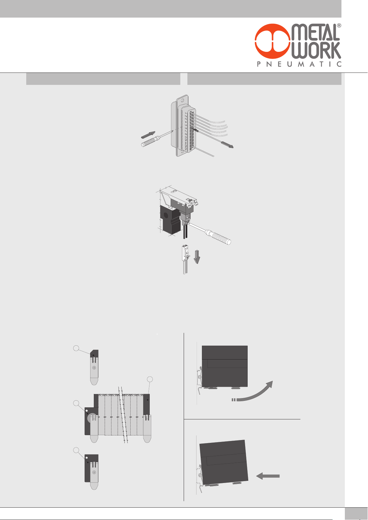
ISTRUZIONI VARIE DI MONTAGGIO
B
A
A
B
A
A
A
GENERAL ASSEMBLY INSTRUCTIONS
Sgancio di un contatto dal connettore D-sub
Inserire un piccolo cacciavite a taglio nella
finestra corrispondente al contatto da togliere.
Premere leggermente con il cacciavite ed
estrarre il filo nella direzione indicata.
Sgancio del connettore dall’elettropilota
Premere con il cacciavite o con le dita nel
punto indicato ed estrarre il connettore
secondo la direzione indicata.
Releasing a contact from the D-sub connector
Insert a small cutting screwdriver into the
window corresponding to the contact to
remove.
Press gently with the screwdriver and extract
the wire in the direction indicated.
Releasing the connector from the electro-pilot
Press the point indicated with the screw driver
or your fingers and extract the connector in
the direction indicated.
Montaggio delle staffe di collegamento su barra DIN
Fissare le staffe sia sul terminale cieco B e sul terminale di ingresso A
mediante la vite in dotazione (Fig. 1). Agganciare la parte posteriore
della staffa alla barra DIN e premere nella direzione indicata per
ottenere l’aggancio (Fig. 2). Per ottenere lo sgancio dalla barra DIN
agire con forza nella direzione indicata (Fig. 3).
Fig. 1 Fig. 2
A
B
A
A
Fitting the connection brackets to a DIN bar
Fix the brackets both onto blind terminal B and input terminal A with the
screws supplied. (Fig.1). Fit the rear part of the bracket to the DIN bar
in the direction indicated to obtain engagement. (Fig. 2)
For release from the DIN bar, use force in the direction indicated. (Fig.3)
Fig. 3
7
Page 8
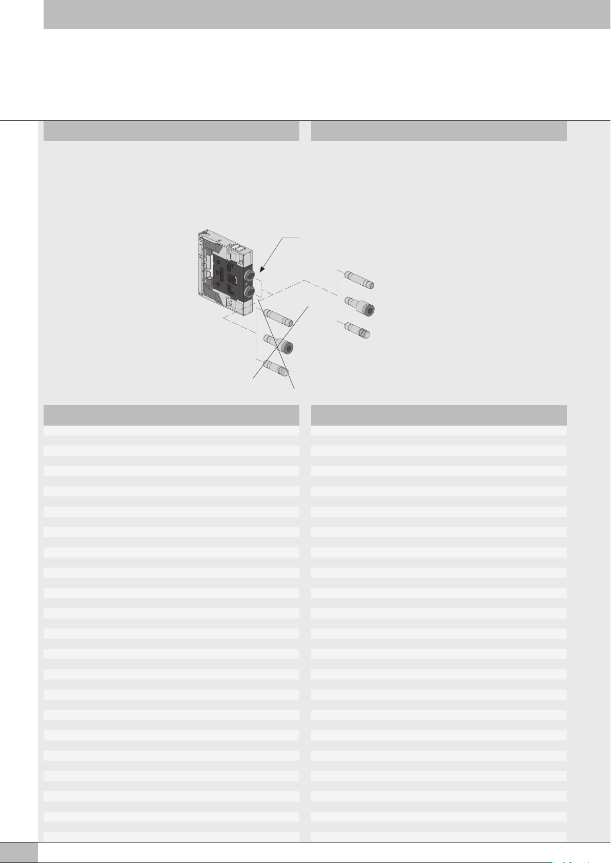
ATTENZIONE
Per tubo Ø8
NON UTILIZZARE RACCORDI AUTOMATICI SERIE R UTILIZZARE SOLO
RACCORDI AUTOMATICI MINIATURIZZATI SERIE RL FOX
NOTE
For tube Ø8
DO NOT USE R SERIES PUSH-IN FITTINGS USE JUST RL FOX SERIES
MINIATURE PUSH-IN FITTINGS
Ø8
R7 Ø8
R8 Ø8/...
R9 Ø8
NOTE NOTES
RL7 Ø8
RL8 Ø8/...
RL9 Ø8
8
www.metalwork.eu
M0060401 ITA_GB - IM02 - 05/2018
 Loading...