

Page 1
HEAVY DUTY MULTIMACH MANUALE D’USO
HEAVY DUTY MULTIMACH USER MANUAL
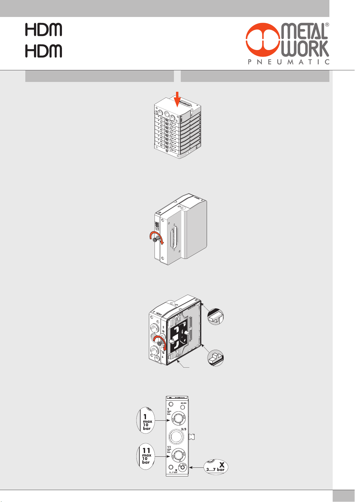
MONTAGGIO E COLLAUDO PNEUMATICO
Disporre le valvole nella sequenza desiderata,
avendo cura di controllare che i dentini “A” di
ogni carter si incastrino nella
successiva e anche nell’apposita sede del
terminale cieco, verificando anche che la
guarnizione “B” sia in sede. Appoggiare il
terminale cieco su di un piano. Esercitare una
spinta di alcuni chilogrammi sul terminale di
ingresso, pewr compattare bene le valvole tra
loro..
Serrare il grano di bloccaggio posteriore della
prima valvola con chiave esagonale CH 2.5
con coppia di serraggio di 2 Nm.
ASSEMBLY AND PNEUMATIC TESTING
Position the valves in the desired sequence,
making sure the small teeth “A” of each guard
engage with the next one and in the seat of
the blind terminal.
Also check that gasket “B” rests in its seat.
Place the blind terminal on a flat surface.
Apply a thrust of several kilograms on the
input terminal to compact the valves properly
one against the other.
Tighten the rear locking grub screw of the first
valve with Allen key CH 2.5 to a torque of
2 Nm.
Serrare il grano di bloccaggio anteriore con
chiave esagonale CH 2.5 con coppia di
serraggio di 2 Nm. Proseguire con la stessa
modalità al serraggio di tutte le valvole.
Dopo il montaggio è necessario effettuare il
collaudo pneumatico dell’isola controllando
le tenute generali. Tappare le bocche di uscita
delle valvole e collegare all’alimentazione le
bocche del terminale di ingresso
contrassegnate dai numeri identificativi
1, 11, X. La pressione da utilizzare per il
collaudo deve essere compresa tra i due
valori limite indicati sul terminale di ingresso
vicino ad ogni connessione.
Tighten the front locking grub screw with Allen
A
A
B
key CH 2.5 to a torque of 2 Nm.
Follow the same procedure to tighten all the
valves.
After fitting it is necessary to perform the
pneumatic test on the island to check general
tightness. Plug the valve output fittings and
connect the terminal input fittings marked with
identification numbers 1, 11, X to the supply.
The pressure used for the test must always be
between the two limit values indicated on the
terminal input close to each connection.
1
Page 2
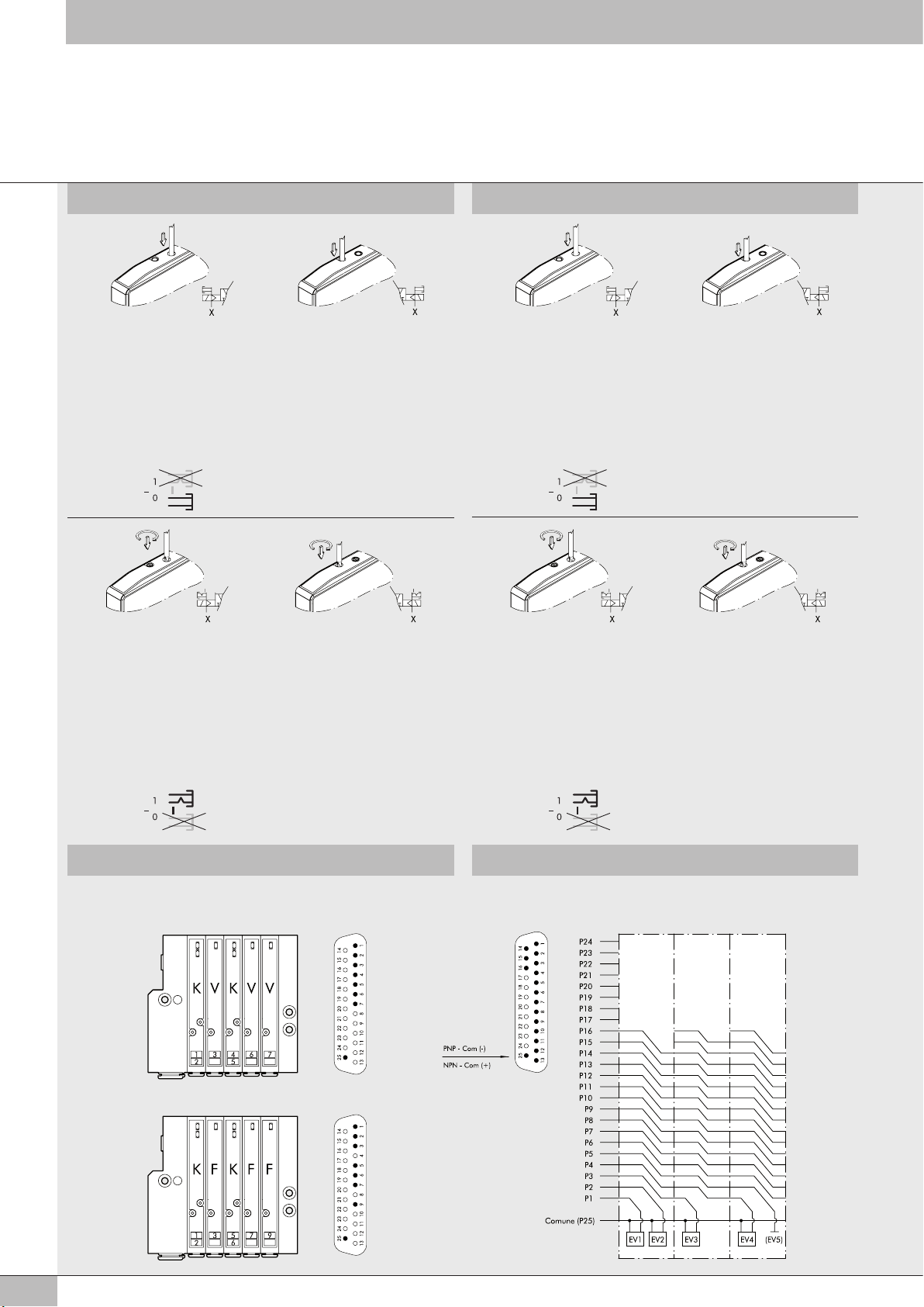
COMANDI MANUALI MANUAL CONTROLS
MANUALE MONOSTABILE BOCCHE 2 servoassistito
• Premere il pulsante fino alla battuta,
• Tenere premuto il manuale in posizione
(non è necessario per la valvola bistabile tipo K).
• Rilasciare il manuale:
- Il manuale ritorna nella posizione di riposo.
- Le valvole tipo I, W, L, V, F e O si riposizionano
- La valvola tipo K resta commutata.
N.B.:
L’alimentazione X dei pilotaggi deve essere presente.
• Il codice di riferimento per il comando monostabile é quello con finale “0” (“2” per le tipo F)
Esempio: 707203053
MANUALE BISTABILE BOCCHE 2 servoassistito
• Premere il pulsante fino alla battuta,
quindi ruotarlo in senso orario di 90°
• Lasciare il manuale in posizione.
• Ruotare il manuale in senso antiorario di 90°,
quindi rilasciarlo.
- Il manuale ritorna nella posizione di riposo.
- Le valvole tipo I, W, L, V, F e O si riposizionano.
- La valvola tipo K resta commutata.
N.B.:
L’alimentazione X dei pilotaggi deve essere presente.
• Il codice di riferimento per il comando bistabile é quello con finale “1” (“3” per le tipo F)
MANUALE MONOSTABILE BOCCHE 4 servoassistito
• Premere il pulsante fino alla battuta.
• Tenere premuto il manuale in posizione
(non è necessario per la valvola bistabile tipo K).
• Rilasciare il manuale.
Il manuale ritorna nella posizione di riposo.
- Le valvole tipo I, W, L, O si riposizionano.
- La valvola tipo K resta commutata.
Nelle valvole tipo V, F questo manuale non è presente.
N.B.:
L’alimentazione X dei pilotaggi deve essere presente.
MANUALE BISTABILE BOCCHE 4 servoassistito
• Premere il pulsante fino alla battuta,
quindi ruotarlo in senso orario di 90°
• Lasciare il manuale in posizione.
• Ruotare il manuale in senso antiorario di 90°,
quindi rilasciarlo.
- Il manuale ritorna nella posizione di riposo.
- Le valvole tipo I, W, L, O si riposizionano.
- La valvola tipo K resta commutata.
Nelle valvole tipo V, F questo manuale non è presente.
N.B.:
L’alimentazione X dei pilotaggi deve essere presente.
MONOSTABLE OVERRIDE PORT 2 servo-assisted
• Press and hold the manual control in position
(not necessary for bistable type K valve)
• Release the manual control:
- The manual control returns to the home position.
- Valves type I, W, L, V, F, and O reposition.
- The type K valve remains switched.
N.B.: The pilot power supply X must be present.
• The reference code for the monostable control ends in 0 (2 for type F).
Example: 707203053
BISTABLE OVERRIDE PORT 2 servo-assisted
• Press the manual control right in then turn it
clockwise 90 degrees and Leave it in position.
• Rotate the manual control 90 degrees anticlockwise,
and then release it.
- The manual control returns to the home position.
- Valves type I, W, L, V, F, and O reposition.
- The type K valve remains switched
N.B.: The pilot power supply X must be present.
• The reference code for the monostable control ends in 1 (3 for type F).
MONOSTABLE OVERRIDE PORT 4 servo-assisted
• Press and hold the manual control in position
(not necessary for bistable type K valve)
• Release the manual control:
- The manual control returns to the home position.
- Valves type I, W, L, V and F reposition.
- The type K valve remains switched.
With type F and V valves, this manual control is not present.
N.B.: The pilot power supply X must be present.
BISTABLE OVERRIDE PORT 4 servo-assisted
• Press the manual control right in then turn it 90
degrees clockwise and Leave it in position.
• Rotate the manual control 90 degrees anticlockwise,
and then release it:
- The manual control returns to the home position.
- Valves type I, W, L and O reposition.
- The type K valve remains switched
With type F and V valves, this manual control is not present.
N.B.: The pilot power supply X must be present.
Esempio: 707203053
Example: 707203053
SCHEMA ELETTRICO WIRING DIAGRAM
NOTA: la monostabile tipo “F”
a differenza della monostabile tipo “V”,
utilizza un PIN solo (come la “V”)
ma occupa 2 segnali.
NOTE: The type F monostable valve
uses one PIN only (like the V)
but occupies 2 signals.
Common
Bistable
or
n° 2 3/2
5/2
mostable
type “ V “
5/2
mostable
type “ F “
2
Page 3
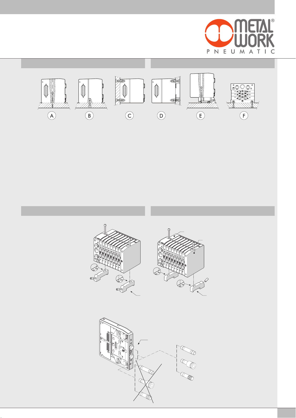
COME FISSARE L’ ISOLA FIXING THE BASE
A Fissaggio dall’alto tramite terminale d’ingresso 1 o 1-11 e
terminale cieco.
B C Fissaggio tramite terminale d’ingresso 1 o 1-11 e terminale cieco,
utilizzando i filetti M5 presenti sui lati inferiore e posteriore dei
terminali.
D Fissaggio tramite terminale d’ingresso 1 o 1-11 e terminale cieco,
utilizzando i filetti M5 presenti sul lato anteriore dei terminali.
Sulla piastra viene ricavata un’apertura che permette il passaggio
dei tubi.
E Fissaggio su barra DIN tramite terminale d’ingresso 1 o 1-11 e
terminale cieco, utilizzando la staffa ad incastro cod. 0227301600.
F Fissaggio laterale tramite terminale cieco, utilizzando i filetti M4
presenti sul fianco dei terminale.
A Fixing from above using the 1 or 1-1 input terminal and the blind
terminal.
B C Fixing from above using the 1 or 1-1 input terminal and the blind
terminal, using the M5 threads on the bottom and the rear of the
terminals.
D Fixing from above using the 1 or 1-1 input terminal and the blind
terminal, using the M5 threads on the front of the terminals.
An opening for the pipes is made in the plate.
E Fixing on the DIN bar with end-plate 1 or 1-11 and blind and plate,
using the push-in bracket code 0227301600.
F Lateral fixing using the blind terminal, and its the M4 threads on the
side lateral.
Note: The sole fixing admitted is the one showed.
NB.: fissaggio permesso solamente come indicato in figura.
ISTRUZIONI VARIE DI MONTAGGIO GENERAL ASSEMBLY INSTRUCTIONS
MONTAGGIO DELLE STAFFE DI
COLLEGAMENTO SU BARRA DIN
Fissare le staffe sia sul terminale
cieco a e sul terminale di ingresso
b mediante la vite in dotazione.
Le staffe possono essere orientate
b
FITTING THE CONNECTION
BRACKETS TO A DIN BAR
Fix the brackets both onto blind ter
a
minal a and input terminal b with
the screws supplied.
Brackets positioning like Y or Z.
come indicato in Y o in Z.
-
ATTENZIONE
Per tubo ø8
NON UTILIZZARE RACCORDI
AUTOMATICI SERIE R
UTILIZZARE SOLO RACCORDI
AUTOMATICI MINIATURIZZATI
SERIE RL
ZY
NOTE
For tube ø8
DO NOT USE R SERIES PUSH-IN
FITTINGS USE JUST RL SERIES
MINIATURE PUSH-IN FITTINGS
ø8
RL7 ø8
RL8 ø8/...
R7 ø8
RL9 ø8
R8 ø8/...
R9 ø8
3
Page 4
INCONVENIENTI CAUSE RIMEDI
All’isola sono
collegati diversi
attuatori:
quando un cilindro
Il flusso di scarico
da una valvola
disturba una valvola
adiacente.
Interporre un separatore
di scarico tra le due
valvole adiacenti.
scambia gli altri
cilindri
si muovono.
In un’isola con
terminale di tipo 1
alcune valvole non
scambiano.
E’ richiesta
troppa portata
simultaneamente e
ai piloti non arriva
Installare il terminale
1-11 ed alimentare
separatamente
l’asservimento piloti X.
sufficiente pressione
di pilotaggio (3 bar).
Alcune valvole non
hanno sufficiente
portata.
E’ richiesta
troppa portata
simultaneamente alle
Installare un terminale
supplementare (destro)
valvole.
Al ripristino
di un arresto
d’emergenza le
valvole non
scambiano.
L’emergenza
ha tagliato
l’alimentazione
pneumatica ma non
quella elettrica; al
riavvio l’aria passa
da alcune valvole
che sono già eccitate
e non arriva ai
piloti.
Installare il terminale
1-11 ed alimentare
separatamente
l’asservimento piloti X,
oppure
l’emergenza deve
togliere anche
l’alimentazione elettrica e
ripristinarla solo dopo il
ripristino della pressione.
PROBLEM CAUSE REMEDY
A number of
actuators are
connected to
the valve island:
The air discharged
from one valve
interferes with the
adjacent valve.
Interpose a discharge
separator between two
adjacent valves.
when a cylinder
is activated, this
triggers activation
of the other
cylinders.
In a valve island
with a type 1 end
plate, some valves
do not activate.
Excessive air
flow is requested
simultaneously
and the pressure
Mount end plate 1-11
and supply solenoid X
slave separately.
delivered to the
solenoids is too low
(3 bar).
The air flow in
some valves is too
low.
Too much air
is requested
simultaneously by
Mount an additional end
plate (RH).
the valves.
When resetting an
emergency stop,
the valves do not
activate.
The emergency
status has cut out the
air supply but not the
power supply; when
the valve is restarted
the air passes
through some valves
that have already
been energised and
Mount end plate 1-11
and supply solenoid X
slave separately
or
the emergency system
must disconnect the
power supply as well and
restore it only after the
air supply is restored.
do not reach the
solenoids.
NOTE NOTES
4
www.metalwork.eu
M0060402 ITA_GB - IM07 - 05/2018
 Loading...