

Page 1
I
GB
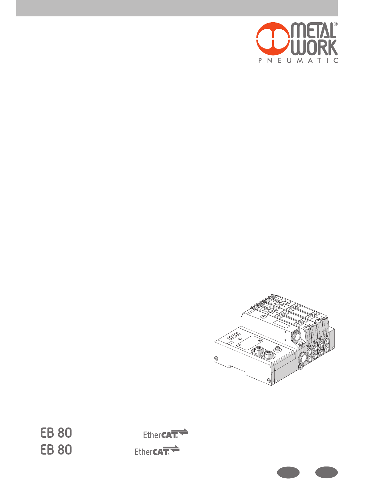
MANUALE D'USO
USER MANUAL
Page 2

2
INDICE
IMPIEGO AMMESSO PAG. 4
DESTINATARI PAG. 4
1. INSTALLAZIONE PAG. 4
1.1 INDICAZIONI GENERALI PER L’INSTALLAZIONE PAG. 4
1.2 ELEMENTI ELETTRICI DI CONNESSIONE E SEGNALAZIONE PAG. 4
1.3 COLLEGAMENTI ELETTRICI: PIEDINATURA CONNETTORI PAG. 4
1.3.1 Connettore M8 per l’alimentazione del nodo e delle uscite PAG. 4
1.3.2 Connettore M12 per la connessione alla rete EtherCAT PAG. 5
1.4 ALIMENTAZIONE ELETTRICA PAG. 5
1.4.1 Tensione di alimentazione PAG. 5
1.4.2 Corrente assorbita PAG. 6
1.5 COLLEGAMENTO ALLA RETE PAG. 6
1.5.1 Impiego di switch PAG. 6
2. MESSA IN SERVIZIO PAG. 7
2.1 CONNESSIONI AL SISTEMA EB 80 EtherCAT PAG. 7
2.2 INSTALLAZIONE DEL SISTEMA EB 80 IN UNA RETE EtherCAT PAG. 7
2.2.1 File di configurazione ESI PAG. 7
2.2.2 Assegnazione dell’indirizzo PAG. 7
2.3 CONFIGURAZIONE DEL SISTEMA EB 80 PAG. 7
2.4 OCCUPAZIONE DEGLI INDIRIZZI PAG. 8
2.5 CONFIGURAZIONE DEL SISTEMA EB 80 IN UNA RETE EtherCAT PAG. 8
2.5.1 Assegnazione dei bit di dati alle uscite delle basi per elettrovalvole PAG. 8
2.5.2 Indirizzi di uscita degli elettropiloti, esempi PAG. 8
2.5.3 Configurazione dei parametri dell’unità - 0x8001:02 – Fail safe output PAG. 9
2.5.3.1 Parametri all’avvio - 0x8001:03 – System start PAG. 9
2.5.3.2 Visualizzazione ingressi analogici 0x8001:04 – Visualization of analog values PAG. 9
2.5.3.3 Formato dati degli input analogici 0x8001:05 – Analog input data format PAG. 9
3. ACCESSORI PAG. 10
3.1 INTERMEDIO - M CON ALIMENTAZIONE ELETTRICA SUPPLEMENTARE PAG. 10
3.2 CONNESSIONE ELETTRICA ADDIZIONALE - E0AD PAG. 10
3.2.1 Elementi elettrici di connessione e segnalazione PAG. 10
3.2.1.1 Collegamenti elettrici: piedinatura connettore M8 per l’alimentazione della Connessione elettrica Addizionale PAG. 10
3.2.2 Indirizzamento della Connessione elettrica Addizionale - E0AD PAG. 11
3.3 MODULI DI SEGNALI - S PAG. 11
3.3.1 Modulo Input digitali PAG. 11
3.3.1.1 Tipo di ingressi e alimentazione PAG. 11
3.3.1.2 Collegamenti elettrici PAG. 11
3.3.1.3 Polarità 0x8020 - Polarity DI8 e 0x8070 Polarity DI16 PAG. 11
3.3.1.4 Stato di attivazione 0x8021 - Activation state DI8 - 0x8071 Activation state DI16 PAG. 12
3.3.1.5 Persistenza del segnale 0x8022 - Signal extension DI8 - 0x8072 Signal extension DI16 PAG. 12
3.3.1.6 Filtro di Input 0x8023 - Debounce time DI8 - 0x8073 Debounce time DI16 PAG. 12
3.3.2 Modulo Output digitali PAG. 12
3.3.2.1 Tipo di uscita e alimentazione PAG. 12
3.3.2.2 Collegamenti elettrici PAG. 12
3.3.2.3 Polarità 0x8030 - Polarity DO8 - 0x8080 Polarity DO16 PAG. 12
3.3.2.4 Stato di attivazione 0x8031 - Activation State DO8 - 0x8081 Activation State DO16 PAG. 13
3.3.2.5 Stato di sicurezza 0x8032 - Fail safe DO8 - 0x8082 Fail safe DO16 PAG. 13
I
Page 3

3
I
3.3.2.6 Guasti e allarmi PAG. 13
3.3.3 Modulo 6 Output digitali M8 + alimentazione elettrica PAG. 13
3.3.3.1 Alimentazione ausiliari PAG. 13
3.3.4 Modulo 4 Input analogici M8 PAG. 13
3.3.4.1 Collegamenti elettrici: piedinatura connettore M8 PAG. 13
3.3.4.2 Range Segnale 0x8050 - Signal range AI PAG. 14
3.3.4.3 Filtro valore misurato 0x8051 - Filter measured value AI PAG. 14
3.3.4.4 Fondo Scala utente 0x8052 - User full scale AI PAG. 14
3.3.4.5 Collegamento dei sensori PAG. 15
3.3.5 Modulo 4 Output analogici M8 PAG. 15
3.3.5.1 Collegamenti elettrici: piedinatura connettore M8 PAG. 15
3.3.5.2 Range Segnale 0x8060 - Signal range AO PAG. 15
3.3.5.3 Fondo Scala utente 0x8061 - User full scale AO PAG. 16
3.3.5.4 Monitor Minimo 0x8062 - Monitor lowest AO PAG. 16
3.3.5.5 Monitor Massimo 0x8063 - Monitor Highest AO PAG. 16
3.3.5.6 Valore minimo 0x8064 Lowest valve AO / Valore massimo 0x8065 Highest valve AO PAG. 16
3.3.5.7 Fail Safe Output 0x8066 - Fail Safe Output AO PAG. 16
3.3.5.8 Fault mode value 0x8067 - Fault mode value AO PAG. 16
3.3.6 Modulo 4 input analogici M8 per la misura di Temperature PAG. 17
3.3.6.1 Connessioni elettriche dei sensori di temperatura (serie Pt e Ni) PAG. 17
3.3.6.2 Connessioni elettriche delle termocoppie PAG. 17
3.3.6.3 Parametri dell’unità PAG. 18
4. DIAGNOSTICA PAG. 20
4.1 DIAGNOSTICA DEL NODO EtherCAT PAG. 20
4.2 DIAGNOSTICA DEL SISTEMA EB 80 – CONNESSIONE ELETTRICA PAG. 20
4.3 DIAGNOSTICA DEL SISTEMA EB 80 – BASE VALVOLE PAG. 22
4.4 DIAGNOSTICA DEL SISTEMA EB 80 – MODULI SEGNALI - S PAG. 22
4.4.1 Diagnostica dei Moduli segnali - S – Input Digitali PAG. 22
4.4.2 Diagnostica dei Moduli segnali - S – Output Digitali PAG. 22
4.4.3 Diagnostica dei Moduli segnali - S – Input Analogici PAG. 23
4.4.4 Diagnostica dei Moduli segnali - S – Output Analogici PAG. 23
4.4.5 Diagnostica dei Moduli segnali - S – Ingressi Analogici per misura di temperature PAG. 24
4.5 DIAGNOSTICA DEL SISTEMA EB 80 – CONNESSIONE ELETTRICA ADDIZIONALE PAG. 24
5. LIMITI DI CONFIGURAZIONE PAG. 24
6. DATI TECNICI PAG. 25
6.1 CONNESSIONE ELETTRICA EtherCAT PAG. 25
6.2 MODULI DI SEGNALI - S - INPUT DIGITALI PAG. 25
6.3 MODULI DI SEGNALI - S - OUTPUT DIGITALI PAG. 25
6.4 MODULI DI SEGNALI - S - OUTPUT DIGITALI + ALIMENTAZIONE ELETTRICA PAG. 26
6.5 MODULI DI SEGNALI - S - INPUT ANALOGICI PAG. 26
6.6 MODULI DI SEGNALI - S - OUTPUT ANALOGICI PAG. 26
6.7 MODULI DI SEGNALI - S - INPUT ANALOGICI PER LA MISURA DI TEMPERATURE PAG. 27
Page 4
4
La Connessione Elettrica EtherCAT consente il collegamento del sistema EB 80 ad una rete EtherCAT. Conforme alle specifiche EtherCAT offre funzioni
di diagnostica ed è disponibile nella configurazione fino a 128 Out per elettro piloti, 128 out digitali, 128 Input digitali, 16 out analogici, 16 input
analogici e 16 Input per misura di temperature.
IMPIEGO AMMESSO
Il manuale è rivolto esclusivamente ad esperti qualificati nelle tecnologie di controllo e automazione che abbiano esperienza nelle operazioni di
installazione, messa in servizio, programmazione e diagnostica di controllori a logica programmabile (PLC) e sistemi Bus di Campo.
DESTINATARI
1. INSTALLAZIONE
1.1 INDICAZIONI GENERALI PER L’INSTALLAZIONE
Onde evitare movimenti incontrollati o danni funzionali, prima di iniziare qualsiasi intervento di installazione o manutenzione scollegare:
• Alimentazione dell’aria compressa;
• Alimentazione elettrica dell’elettronica di controllo e delle elettrovalvole / uscite.
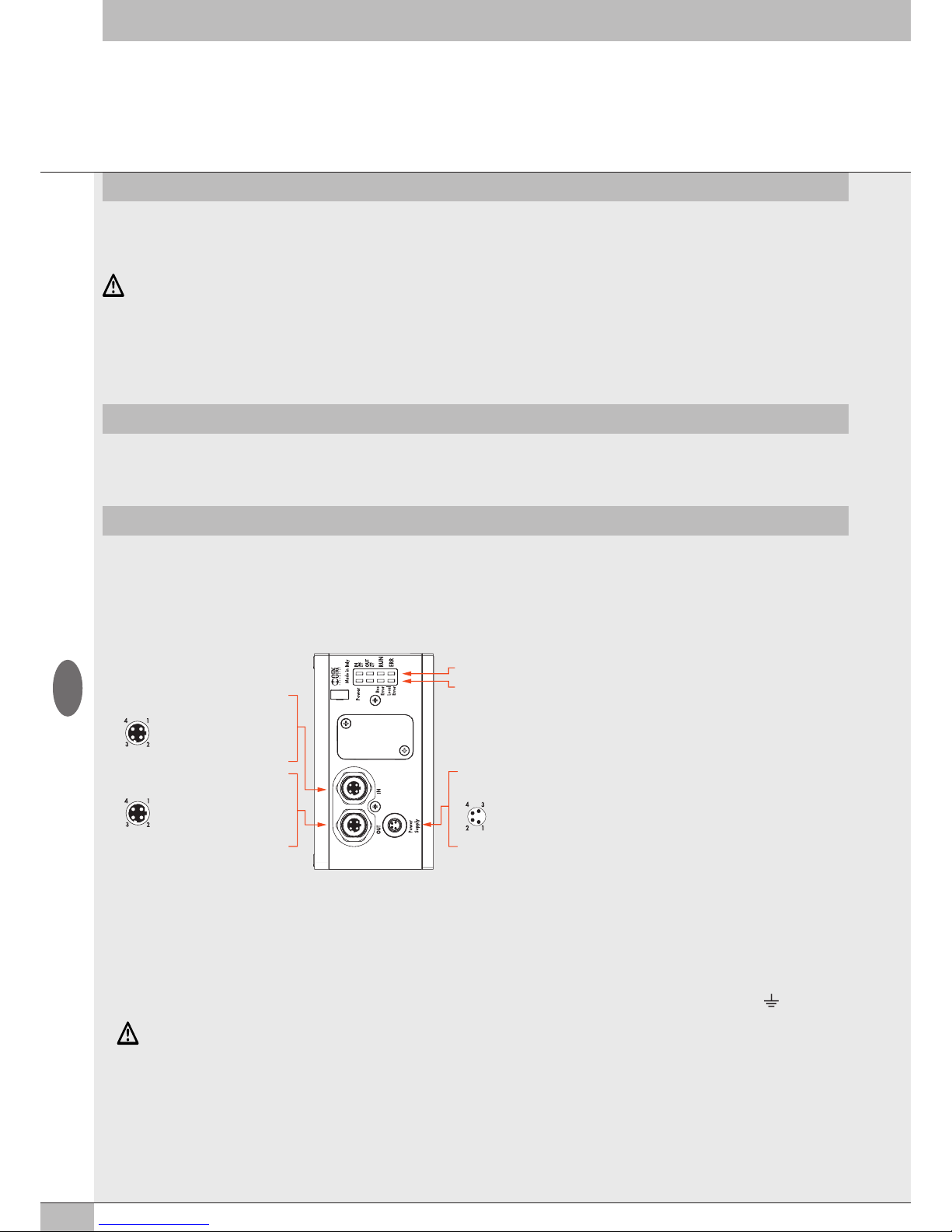
1.2 ELEMENTI ELETTRICI DI CONNESSIONE E SEGNALAZIONE
ATTENZIONE
La mancanza di collegamento a terra può causare, in caso di scariche elettrostatiche, malfunzionamenti e danni irreversibili.
Per garantire il grado di protezione IP65 è necessario che gli scarichi siano convogliati e che il connettore M12 non utilizzato sia tappato.
1.3 COLLEGAMENTI ELETTRICI: PIEDINATURA CONNETTORI
1.3.1 Connettore M8 per l’alimentazione del nodo e delle uscite
1 = +24V Alimentazione nodo EtherCAT e moduli input/output
2 = +24V Alimentazione ausiliaria valvole
3 = GND
4 = GND
Il dispositivo deve essere collegato con la terra utilizzando la connessione del terminale di chiusura, indicata con il simbolo PE
ATTENZIONE
Utilizzare il Sistema EB 80 EtherCAT solo nel seguente modo:
• Per gli usi consentiti in ambito industriale;
• Sistemi completamente assemblati e in perfette condizioni;
• Osservare i valori limite specificati per dati elettrici, pressioni e temperature;
• Per l’alimentazione utilizzare esclusivamente alimentatori a norma IEC 742/EN60742/VDE0551 con resistenza minima di isolamento di 4kV
(PELV).
Led di segnalazione diagnostica EtherCAT
Led di segnalazione diagnostica EB 80 Net
Connessione alla rete EtherCAT
Power Supply (Connettore maschio M8)
IN (Connettore femmina M12 codifica D)
OUT (Connettore femmina M12 codifica D)
1 = TD+
2 = RD+
3 = TD4 = RDGhiera metallica = Schermo
1 = TD+
2 = RD+
3 = TD4 = RDGhiera metallica = Schermo
1 = +24V bus (marrone)
2 = +24V valvole (bianco)
3 = GND (blu)
4 = GND (nero)
Connessione per l’alimentazione del nodo e
per l’alimentazione ausiliaria delle valvole
I
Page 5
5
1.3.2 Connettore M12 per la connessione alla rete EtherCAT
1 = TD+
2 = RD+
3 = TD4 = RDGhiera metallica = Schermo
I connettori di rete sono M12 con codifica di tipo D secondo le specifiche EtherCAT; per il collegamento si possono utilizzare cavi Industrial
Ethernet precablati, in modo da evitare i malfunzionamenti dovuti a cablaggi difettosi, o in alternativa connettori M12 maschi metallici 4 poli
Industrial Ethernet ricablabili.
Per il collegamento al Master può essere necessario un cavo di collegamento RJ45 – M12 maschio cod. D, che può essere realizzato con i
seguenti codici del catalogo Metal Work:
• 0240005050 Connettore RJ45 a 4 contatti secondo IEC 60 603-7
• 0240005093 / 095 /100 Connettore diritto per bus M12 codifica D con cavo
ATTENZIONE
Per una corretta comunicazione, utilizzare esclusivamente cavi a norma Industrial Ethernet Cat.5 /Classe D 100 MHz come quello proposto nel
catalogo Metal Work. Errori di installazione possono dare luogo a errori di trasmissione con conseguenti malfunzionamenti dei dispositivi.
Le cause più frequenti di malfunzionamenti dovuti alla trasmissione dati difettosa sono:
• Errato collegamento dello schermo o dei conduttori
• Cavi troppo lunghi o non adatti
• Componenti di rete per derivazioni non adatti
1.4 ALIMENTAZIONE ELETTRICA
Per l’alimentazione elettrica si utilizza un connettore M8 femmina 4 poli; l’alimentazione ausiliaria delle valvole è separata da quella del bus, per cui
nel caso sia necessario, si può disinserire l’alimentazione delle valvole mentre la linea bus resta attiva. La mancanza di alimentazione ausiliaria viene
segnalata dal lampeggio del Led Power e dal lampeggio contemporaneo di tutti i Led delle elettrovalvole. Il guasto viene segnalato al Master che
deve provvedere ad una adeguata gestione dell’allarme.
ATTENZIONE
Disattivare la tensione prima di inserire o disinserire il connettore (pericolo di danni funzionali)
Utilizzare solamente unità di valvole completamente assemblate.
Per l’alimentazione utilizzare esclusivamente alimentatori a norma IEC 742/EN60742/VDE0551 con resistenza minima di isolamento di 4kV (PELV).
1.4.1 Tensione di alimentazione
Il sistema consente un range di alimentazione ampio, da 12VDC -10% a 24VDC +30% (min 10.8, max 31.2).
ATTENZIONE
Una tensione maggiore di 32VDC danneggia irreparabilmente il sistema.
CADUTA DI TENSIONE DEL SISTEMA
La caduta di tensione dipende dalla corrente massima assorbita dal sistema e dalla lunghezza del cavo di connessione al sistema.
In un sistema alimentato a 24VDC con lunghezze del cavo fino a 20 m non è necessario tenere conto delle cadute di tensione.
In un sistema alimentato a 12VDC, si deve garantire che la tensione fornita sia sufficiente per il corretto funzionamento. È necessario tenere conto
delle cadute di tensione dovute al numero di elettrovalvole attive, al numero di valvole comandate simultaneamente e alla lunghezza del cavo.
La tensione reale che arriva agli elettropiloti deve essere almeno 10.8 V.
Riportiamo qui in sintesi l’algoritmo per la verifica.
Corrente massima: I max [A] = (N° elettropiloti comandati simultaneamente x 3.2) + (N° elettropiloti attivi x 0.3)
VDC
Caduta di tensione del cavo di alimentazione M8: ΔV = I max [A] x Rs [0.067Ω/m] x 2L [m]
Ove Rs è la resistenza del cavo ed L la sua lunghezza.
La tensione all’ingresso del cavo, Vin deve essere almeno pari a 10.8 V + ΔV
Esempio:
Tensione di alimentazione 12 V, cavo lungo 5 m, si attivano contemporaneamente 3 piloti mentre altri 10 sono già attivi:
I max = (3 x 3.2) + (10 x 0.3) = 1.05 A
12
ΔV = (1.05 x 0.067) x (2 x 5) = 0.70 V
Perciò all’alimentatore serve una tensione maggiore o uguale a 10.8 + 0.7 = 11.5 V
Vin =12 V > 11.5 → OK
I
Page 6
6
La corrente massima per il comando delle elettrovalvole, erogabile dal terminale connessione elettrica EtherCAT è 4 A.
Nel caso in cui la corrente massima sia superiore, è necessario inserire nel sistema un Intermedio – M con alimentazione elettrica supplementare.
Vedi paragrafo 3.1.
1.5 COLLEGAMENTO ALLA RETE
Per una corretta installazione, fare riferimento alle linee guida dell’Associazione ETG (EtherCAT Tecnology Group).
Vedere http://www.ethercat.org
1.5.1 Impiego di switch
La Connessione Elettrica EB 80 EtherCAT è dotata di due porte di comunicazione EtherCAT, che consentono la realizzazione di reti lineari.
La rete può essere suddivisa in ulteriori segmenti, utilizzando degli switch supplementari.
Assicurarsi che i dispositivi utilizzati siano conformi alle specifiche Industrial Ethernet e che supportino tutte le funzioni EtherCAT.
1.4.2 Corrente assorbita
Il controllo delle elettrovalvole avviene attraverso una scheda elettronica dotata di microprocessore.
Per garantire un azionamento sicuro della valvola e ridurre il consumo energetico, il comando è di tipo “speed up”, cioè all’elettropilota vengono
forniti 3W per 15 millisecondi e successivamente la potenza viene ridotta gradualmente a 0.3W. Il microprocessore attraverso un comando
PWM regola la corrente circolante nella bobina, che rimane costante indipendentemente dalla tensione di alimentazione e dalla temperatura,
mantenendo di conseguenza inalterato il campo magnetico generato dall’elettropilota.
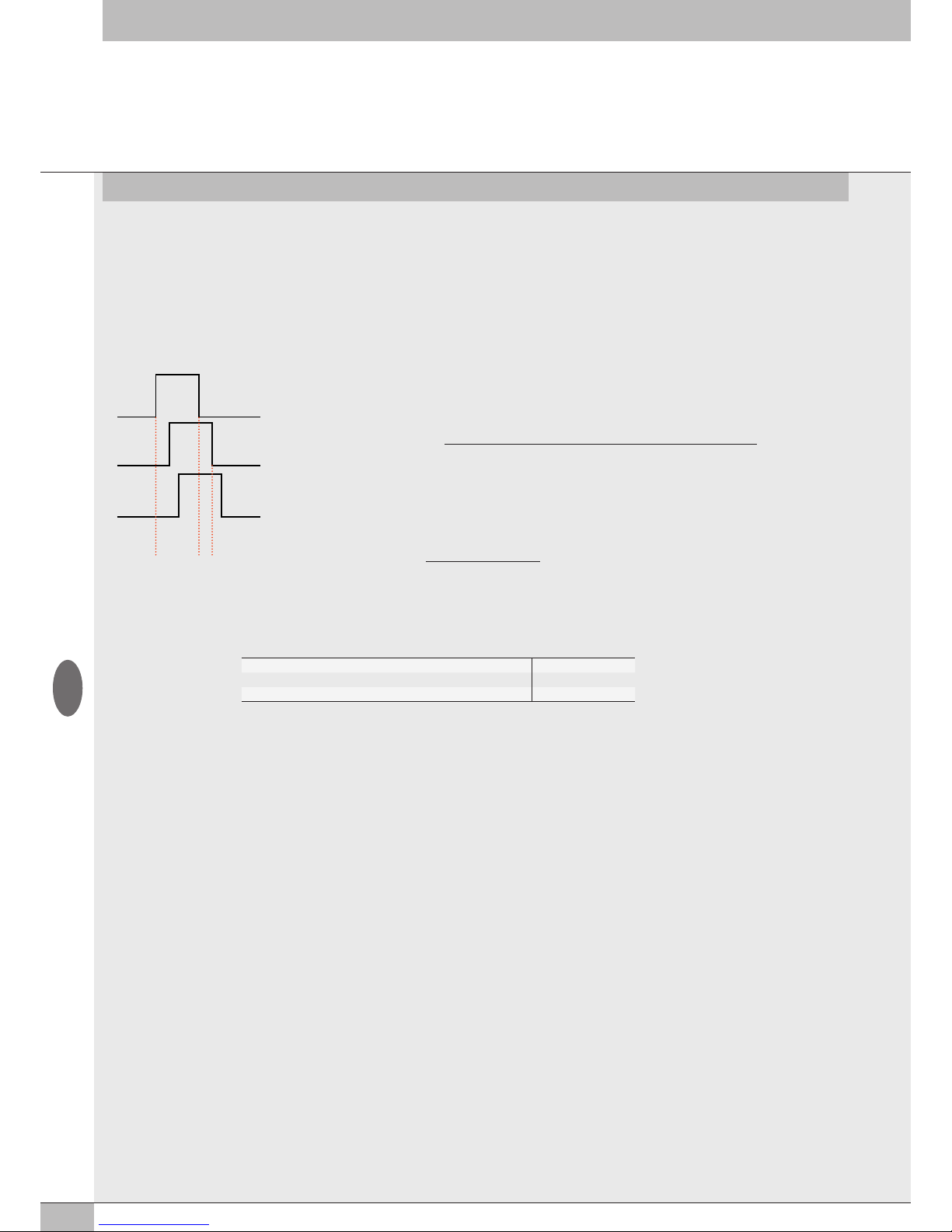
Per dimensionare correttamente l’alimentazione del sistema si deve tener conto di quante valvole dovranno essere comandate simultaneamente*
e quante sono già attive.
*Per comando simultaneo si intende l’attivazione di tutti gli elettropiloti che hanno tra loro una differenza temporale minore di 15 millisecondi.
P1
P3
P2
T2T1
15 ms
T1 = P1 + P2 + P3 = 3 elettropiloti simultanei
T2 = P2 + P3 = 2 elettropiloti simultanei
I max [A] =
(N° elettropiloti simultanei x 3.2) + (N° elettropiloti attivi x 0.3)
VDC
Esempio:
N° elettropiloti simultanei = 10
N° elettropiloti attivi = 15
VDC = Tensione di alimentazione 24
I max =
(10 x 3.2) + (15 x 0.3)
= 1.5 A
24
Potenza totale assorbita durante lo Speed up 3.2 W
Potenza totale assorbita durante la fase di mantenimento 0.3 W
Potenza del terminale elettrico Bus di campo 4 W
Tabella riassuntiva
La potenza totale assorbita in ingresso è uguale alla potenza assorbita dagli elettropiloti più
la potenza assorbita dall’elettronica di controllo delle basi. Per semplificare il calcolo si può
considerare 3.2W la potenza di ogni elettropilota simultaneo e 0.3W la potenza di ogni
elettropilota attivo.
Alla corrente risultante deve essere aggiunto il consumo del terminale elettrico bus di campo uguale a 180 mA.
I
Page 7
7
2. MESSA IN SERVIZIO
ATTENZIONE
Disattivare la tensione prima di inserire o disinserire i connettori (pericolo di danni funzionali).
Collegare il dispositivo a terra, mediante un conduttore appropriato.
La mancanza di collegamento a terra può causare, in caso di scariche elettrostatiche, malfunzionamenti e danni irreversibili.
Utilizzare solamente unità di valvole completamente assemblate.
2.1 CONNESSIONI AL SISTEMA EB 80 EtherCAT
Collegare il dispositivo a terra.
Collegare il connettore di ingresso IN alla rete EtherCAT.
Collegare il connettore di uscita OUT al dispositivo successivo. Altrimenti chiudere il connettore con l’apposito tappo per assicurare la protezione IP65.
Collegare il connettore di alimentazione. L’alimentazione del bus è separata dall’alimentazione delle valvole.
È possibile disattivare l’alimentazione delle valvole mantenendo attiva la comunicazione con il controllore EtherCAT.
2.2 INSTALLAZIONE DEL SISTEMA EB 80 IN UNA RETE EtherCAT
2.2.1 File di configurazione ESI
Per installare correttamente il sistema EB 80 in una rete EtherCAT, è necessario importare il file ESI Metalwork_EB80 nel software di
programmazione utilizzato, disponibile sul sito internet Metal Work, all’indirizzo http://www.metalwork.it/ita/download.html
Il file di configurazione ESI del sistema EB 80 EtherCAT, descrive le sue caratteristiche. Deve essere importato nell’ambiente di sviluppo del
controllore, per essere identificato come un dispositivo EtherCAT e configurare correttamente gli Input /Output.
Alternativamente la descrizione del dispositivo è scritta nella sua memoria interna e può essere letta online dal Master.
2.2.2 Assegnazione dell’indirizzo
Sono disponibili due modalità di indirizzamento.
Auto Increment Address: il master rileva la posizione fisica del modulo all’interno della rete e assegna automaticamente l’indirizzo (indirizzamento
topologico). Questo viene perso allo spegnimento del modulo. Alla riaccensione, se la posizione fisica non è cambiata, il master provvede a
riassegnare l’indirizzo precedente. Se la posizione è stata modificata il Master segnala un errore.
Second Slave Address: l’indirizzo può essere assegnato tramite un tool di configurazione, per esempio TwinCAT
@
utilizzando la funzione
”Configured Station Alias”.
Con questa funzione l’indirizzo è memorizzato in maniera permanete nella EEPROM e viene mantenuto anche allo spegnimento del modulo.
2.3 CONFIGURAZIONE DEL SISTEMA EB 80
Prima dell’utilizzo il sistema EB 80 deve essere configurato tramite una procedura che permetta di conoscerne la composizione.
Procedere nel seguente modo:
- scollegare il connettore M8 di alimentazione elettrica;
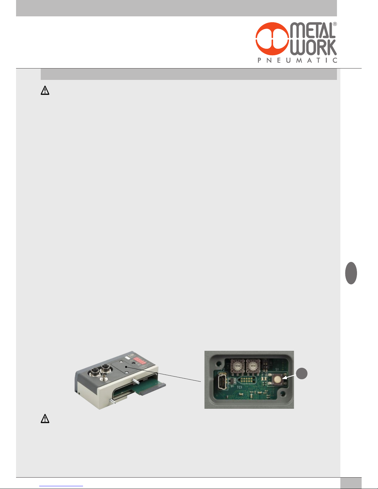
- aprire lo sportello del modulo;
- premere il pulsante "A" e riconnettere il connettore M8 di alimentazione, mantenendo premuto il pulsante"A" fino al lampeggio contemporaneo
di tutti i Led del sistema, basi valvole, moduli di segnale ed isole addizionali.
Il sistema EB 80 è caratterizzato da un'elevata flessibilità. È sempre possibile modificare la configurazione aggiungendo, togliendo o modificando le
basi per valvole, moduli di segnale o isole addizionali.
La configurazione deve essere effettuata dopo ogni modifica del sistema.
Nel caso in cui siano installate isole con connessione elettrica addizionale o Moduli 6 Output digitali M8 + alimentazione elettrica, per essere
configurati correttamente, tutti i moduli devono essere alimentati.
A
ATTENZIONE
In caso di successive modifiche alla configurazione iniziale, potrebbero verificarsi degli spostamenti degli indirizzi delle elettrovalvole. Lo spostamento
avviene nei seguenti casi:
• Inserimento di basi per valvole tra quelle già esistenti
• Sostituzione di una base per valvole con una di altro tipo
• Eliminazione di una o più basi per valvole intermedie
• Aggiunta o eliminazione di isole con connessione elettrica Addizionale tra isole preesistenti.
L’aggiunta o eliminazione di isole addizionali in coda al sistema non comporta lo spostamento degli indirizzi.
I nuovi indirizzi sono successivi a quelli preesistenti.
• Aumento del numero di byte delle basi per valvole (modulo pneumatico) nel caso in cui siano già configurati dei moduli di uscita digitale.
I
Page 8
8
2.4 OCCUPAZIONE DEGLI INDIRIZZI
Il volume di indirizzi messo a disposizione del Master è il seguente:
• 16 byte per basi per valvole (modulo pneumatico), massimo 128 elettropiloti (byte Out da 0 a 15);
• 16 byte per Moduli segnali 8 uscite digitali, massimo 128 uscite digitali totali (byte Out da 16 a 31);
• 22 byte per Moduli segnale 6 uscite digitali + alimentazione, massimo 128 uscite digitali totali (byte Out da 32 a 53);
• 32 byte per Moduli segnale di uscite analogiche, massimo 16 uscite analogiche (byte Out da 54 a 85);
• 16 byte per Moduli di segnali 16 uscite digitali, massimo 128 uscite digitali totali (byte Out da 86 a 101);
• 1 byte di diagnostic (byte In 0).
• 16 byte per Moduli segnale 8 ingressi digitali, massimo 128 ingressi digitali totali (byte In da 1 a 16);
• 32 byte per Moduli segnale di ingressi analogici, massimo 16 ingressi analogici (byte In da17 a 48);
• 48 byte di diagnostica EB 80 I4.0, (byte In da 49 a 96)
• 16 byte per Moduli di segnali 16 ingressi digitali, massimo 128 ingressi digitali totali (byte In da 97 a 112);
• 32 byte per Moduli di segnali di ingressi analogici per la misura di temperature, massimo 16 ingressi analogici (byte In da 113 a 144);
L’indirizzamento di tutti i moduli pneumatici è sequenziale.
L’indirizzamento dei Moduli di segnale è sequenziale per tipologia.
2.5 CONFIGURAZIONE DEL SISTEMA EB 80 IN UNA RETE EtherCAT
Con il dispositivo alimentato e collegato alla rete, effettuare una scansione della rete stessa. Il dispositivo verrà automaticamente rilevato dal Master.
In alternativa, per effettuare la configurazione offline, selezionare dal catalogo hardware del sistema di sviluppo, Il dispositivo EtherCAT EB 80 series
e inserirlo nella configurazione. Al dispositivo vengono assegnati tutti i bytes di uscita e tutti i bytes di ingresso, compreso il byte di stato che indica lo
stato diagnostico del sistema EB 80.
2.5.1 Assegnazione dei bit di dati alle uscite delle basi per elettrovalvole
DO 1-6 DI 1-8 E1 E7
bit 0 bit 1 bit 2 bit 3 ... bit 128
Out 1 Out 2 Out 3 Out 4 ... Out 128
2.5.2 Indirizzi di uscita degli elettropiloti, esempi:
Base per valvole a 3 o 4 comandi – è possibile montare solo valvole a un elettropilota
Tipo di valvola
Valvola a
1 elettropilota
Valvola a
1elettropilota
Falsa valvola
o Bypass
Valvola a
1 elettropilota
Falsa valvola
o Bypass
Valvola a
1 elettropilota
Elettro pilota 1 14 14 - 14 - 14
Uscita Out 1 Out 2 Out 3 Out 4 Out 5 Out 6
Base per valvole a 6 o 8 comandi – è possibile montare valvole a uno o due elettropiloti
Tipo di valvola
Valvola a
2 elettropiloti
Valvola a
1 elettropilota
Falsa valvola
o Bypass
Valvola a
1 elettropilota
Falsa valvola
o Bypass
Valvola a
2 elettropiloti
Elettro pilota 1 14 14 - 14 - 14
Elettro pilota 2 12 - - - - 12
Uscita
Out 1 Out 3 Out 5 Out 7 Out 9 Out 11
Out 2 Out 4 Out 6 Out 8 Out 10 Out 12
Ogni base occupa tutte le posizioni.
Il comando di uscite non connesse, genera un allarme di elettropilota interrotto.
I
Page 9
9
2.5.3 Configurazione dei Parametri dell’unità - 0X8001:02 – Fail safe output
Questa funzione consente di definire lo stato degli elettropiloti delle uscite digitali e analogiche, nel caso di comunicazione interrotta con il Master.
Per il modulo pneumatico sono possibili tre diverse modalità, impostabili con l’oggetto 0x8001:02 – Params_Head_ NetX –SubIndex 002
• Output Reset (default), tutti gli elettropiloti vengono disattivati. 0x8001:02 = 00
• Hold Last State, tutti gli elettropiloti mantengono lo stato in cui si trovavano prima dell’interruzione della comunicazione con il Master.
0x8001:02 = 01
• Output Fault mode, 0x8001:02 = 02. É possibile selezionare il comportamento di ogni singolo pilota tra tre modalità attraverso l’impostazione
dell’oggetto 0x8010:0 - Fail Safe.
L’oggetto è un array di 32 byte, e consente di configurare lo stato di ogni pilota dei moduli pneumatici, riservando 2 bit per ogni canale.
- Valore = 0 Hold Last State, l’elettropilota mantiene lo stato in cui si trovava prima dell’interruzione della comunicazione con il Master.
- Valore = 1 Output Reset (default), l’elettropilota viene disattivato.
- Valore = 2 Output Set, al momento dell’interruzione della comunicazione con il Master l’elettropilota viene attivato.
Esempio: un modulo pneumatico da 8 piloti, in caso di mancata comunicazione con il Master, i primi 4 si attivano e gli altri 4 si disattivano.
Al ripristino della comunicazione, la gestione dello stato degli elettropiloti viene ripreso dal Master. Per evitare movimenti incontrollati, il
Master deve provvedere ad una adeguata gestione dell’evento.
2.5.3.1 Parametri all’avvio - 0x8001:03 – System start
• 0x8001:03 = 0 Parametri esterni/default: ad ogni accensione il sistema deve essere inizializzato dal Master che provvede ad inviare tutti i
parametri di configurazione, come per esempio il tipo di ingresso/uscita ecc.
• 0x8001:03 = 1 Parametri salvati: alla prima accensione i parametri inviati dal Master vengono salvati ed utilizzati per tutte le successive
accensioni. Questo permette un avvio più rapido del sistema.
2.5.3.2 Visualizzazione ingressi analogici 0x8001:04 – Visualization of analog values
• 0x8001:04 = 1 Logica INTEL o Little-endian: memorizzazione che inizia dal byte meno significativo per finire col più significativo.
• 0x8001:04 = 0 Logica Motorola o Big-endian: memorizzazione che inizia dal byte più significativo per finire col meno significativo (default).
2.5.3.3 Formato dati degli input analogici 0x8001:05 – Analog input data format
Consente di impostare il formato dei dati analogici in due modalità:
• 0x8001:05 = 0 Sign + 15 bit - il valore analogico è compreso tra +32767 e -32768 che si ottiene con il massimo valore analogico ammesso
dal tipo di ingresso. I valori sono riportati in tabella.
• 0x8001:05 =1 Linear scaled – il valore analogico misurato è riferito al valore impostato nel campo "Fondo scala utente"
delle "Proprietà Generali" – "Parametri dell’unità del modulo analogico". Può essere impostato singolarmente per ogni canale analogico.
Vedi par. 3.3.4.3 Fondo scala utente.
N° out Out 4 Out 3 Out2 Out1 Out 8 Out 7
Out 6 Out 5
Byte 1 2
bit 7 - 6 5 - 4 3 - 2 1 - 0 7 - 6 5 - 4
3 - 2 1 - 0
Fault mode Set Set Set Set Reset Reset Reset Reset
Valore 2 2 2 2 1 1 1 1
bit 10 10 10 10 01 01 01 01
Byte 10101010 01010101
Hex 0xAA 0x55
Impostazioni 0x8010:1 = 0xAA 0x8010:2 = 0x55
Valore analogico Valore digitale Segnalazione
Tipo di ingresso -10… + 10 V
+11.7 V 32767 Overflow
+ 10 V
-10 V
28095
- 28095
Range nominale
-11.7 -32768 Underflow
Tipo di ingresso -5… + 5 V
+5.8 32767 Overflow
+ 5 V
- 5 V
28095
- 28095
Range nominale
-5.8 -32768 Underflow
Tipo di ingresso 1… + 5 V
+5.8 32767 Overflow
+ 5 V 28095 Range nominale
0 V 0 Underflow
Tipo di ingresso -20 mA … + 20 mA
+23 mA 32767 Overflow
+20mA
- 20mA
28095
- 28095
Range nominale
-23 mA -32768 Underflow
Tipo di ingresso 4 mA … + 20 mA
+23 mA 32767 Overflow
20mA
4 mA
27307
5513
Range nominale
0 mA 0 Underflow
I
Page 10
10
3. ACCESSORI
3.1 INTERMEDIO - M CON ALIMENTAZIONE ELETTRICA SUPPLEMENTARE
Tra le basi delle valvole possono essere installati dei moduli intermedi con alimentazione elettrica supplementare.
Possono servire come alimentazione elettrica supplementare, quando il numero di elettropiloti azionato contemporaneamente è elevato, oppure per
separare elettricamente alcune parti dell’isola da altre, per esempio quando si vuole interrompere l’alimentazione elettrica di alcune elettrovalvole
all’apertura di una protezione della macchina, o alla pressione di un pulsante di emergenza. Solo le elettrovalvole a valle del modulo sono alimentate
dallo stesso. Sono disponibili varie tipologie con funzioni pneumatiche differenti.
La corrente massima per il comando delle elettrovalvole, erogabile dall’intermedio con alimentazione elettrica supplementare è 8 A.
ATTENZIONE
Non può essere utilizzata come funzione di sicurezza, in quanto garantisce solo che non venga effettuata nessuna attivazione elettrica.
Attivazioni manuali o guasti possono causare movimenti involontari. Per maggior sicurezza, scaricare l’impianto pneumatico prima di eseguire
interventi pericolosi.
PIN Colore Funzione
1 Marrone +VDC
2 Bianco +VDC
3 Blu GND
4 Nero GND
+VDC Valvole
+VDC Bus
Linea Bus
+VDC Valvole
+VDC Bus
Linea Bus
+VDC Valvole
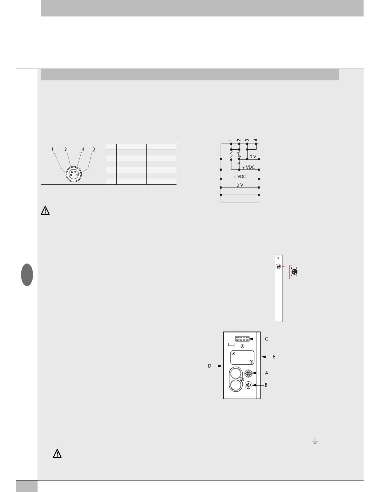
3.2.1 Elementi elettrici di connessione e segnalazione
A Connessione alla rete EB 80 Net
B Connessione per l’alimentazione della Connessione elettrica Addizionale
e per l’alimentazione ausiliaria delle valvole
C Led di segnalazione diagnostica EB 80
D Connessione ai moduli Segnale
E Connessione alle basi per valvole
ATTENZIONE
La mancanza di collegamento a terra può causare, in caso di scariche elettrostatiche, malfunzionamenti e danni irreversibili.
Per garantire il grado di protezione IP65 è necessario che gli scarichi siano convogliati e che il connettore M12 non utilizzato sia tappato.
3.2.1.1 Collegamenti elettrici: piedinatura connettore M8 per l’alimentazione della Connessione elettrica Addizionale
1 = 24VDC Alimentazione Connessione elettrica Addizionale e moduli di Input/Output
2 = 24VDC Alimentazione ausiliaria valvole
3 = GND
4 = GND
Il dispositivo deve essere collegato con la terra utilizzando la connessione del terminale di chiusura, indicata con il simbolo PE
3.2 CONNESSIONE ELETTRICA ADDIZIONALE - E0AD
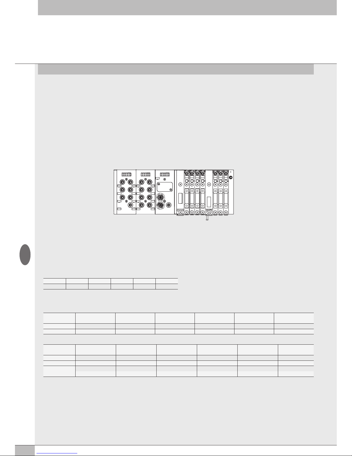
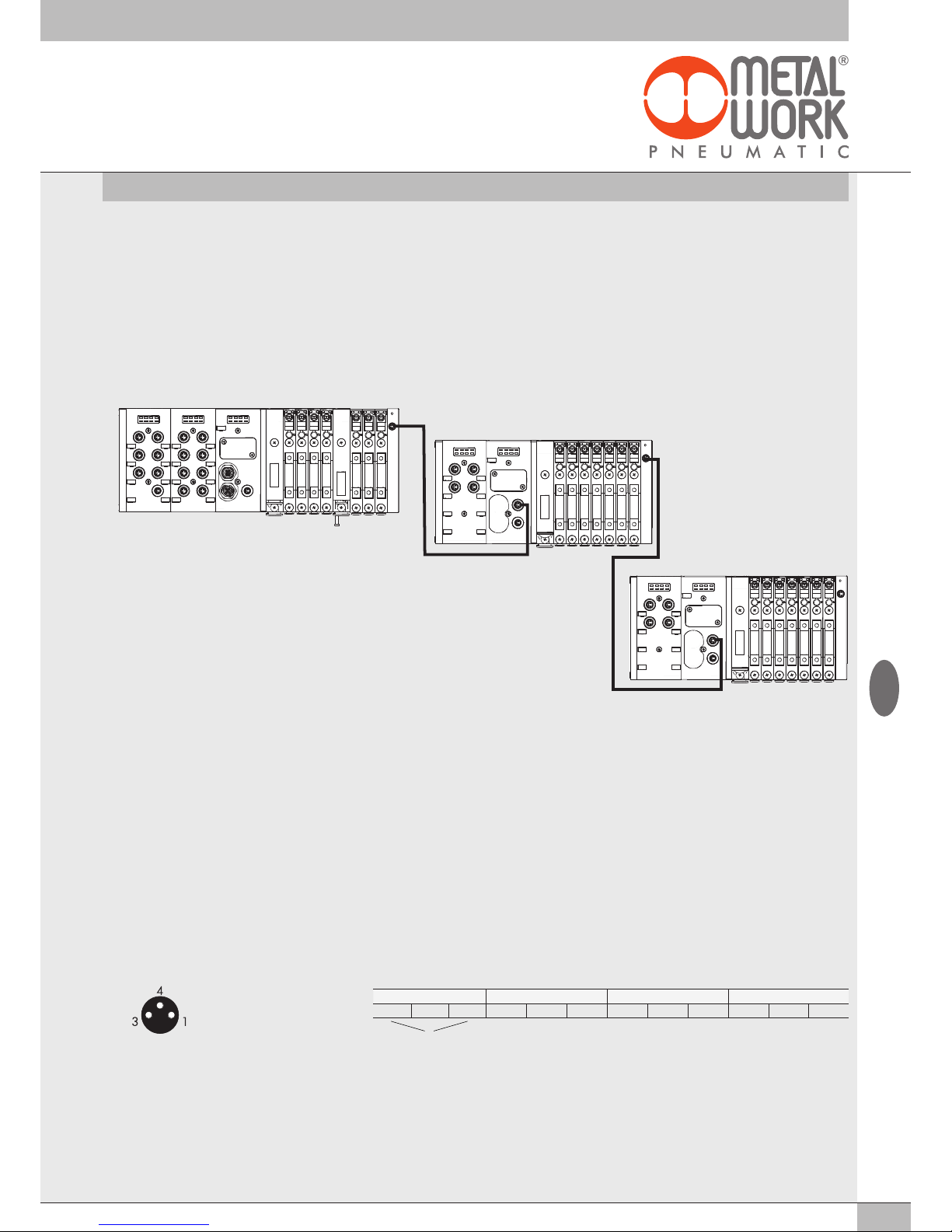
La connessione elettrica Addizionale - E permette di collegare ad un unico nodo EtherCAT diversi sistemi EB 80.
Per fare questo l’isola principale deve essere dotata di un terminale cieco tipo C3, dotato di un connettore M8.
Per consentire il collegamento di più sistemi, tutte le isole addizionali devono essere dotate del terminale cieco
C3, tranne l’ultima che deve montare il terminale cieco C2, dotato dell’apposita terminazione per la linea
seriale EB 80 Net.
Opzionalmente, se è necessaria una predisposizione per futuri ampliamenti, è possibile montare un terminale
cieco C3 anche sull’ultima isola, in questo caso è necessario inserire l’apposito connettore M8 di terminazione
cod. 02282R5000.
Per il corretto funzionamento di tutto il sistema EB 80 Net, utilizzare esclusivamente i cavi M8-M8 precablati,
schermati e twistati, presenti sul catalogo Metal Work.
La connessione elettrica Addizionale, consente di collegare basi per valvole e moduli di segnale - S,
esattamente come per l’isola con nodo EtherCAT.
1 = +24V bus
2 = +24V valvole
3 = GND
4 = GND
Terminale di chiusura con rimando
EB 80 Net (Connettore femmina M8)
1 = CAN H
2 = CAN L
3 = Token
4 = GND
I
Page 11
11
3.2.2 Indirizzamento della Connessione elettrica Addizionale - E0AD
L’indirizzamento di tutti i moduli è sequenziale.
• L’indirizzamento degli elettropiloti delle valvole, inizia dal primo elettropilota del nodo EtherCAT e finisce con l’ultimo elettropilota dell’ultima
isola Addizionale collegata.
• L’indirizzamento dei moduli - S di ingressi digitali, inizia dal primo modulo collegato al nodo EtherCAT e finisce con l’ultimo modulo - S di
ingressi digitali dell’ultima isola Addizionale collegata.
• L’indirizzamento dei moduli - S di uscite digitali, inizia dal primo modulo collegato al nodo EtherCAT e finisce con l’ultimo modulo - S di uscite
digitali dell’ultima isola Addizionale collegata.
• L’indirizzamento dei moduli - S di ingressi analogici, inizia dal primo modulo collegato al nodo EtherCAT e finisce con l’ultimo modulo - S di
ingressi analogici dell’ultima isola Addizionale collegata.
• L’indirizzamento dei moduli - S di uscite analogiche, inizia dal primo modulo collegato al nodo EtherCAT e finisce con l’ultimo modulo - S di
uscite analogiche dell’ultima isola Addizionale collegata.
DO 1-6 DI 1-8 E1 E7
AI 1-4 E8 E15
AI 5-8 E16 E23
3.3 MODULI DI SEGNALI - S
I sistemi EB 80 sono corredati da numerosi moduli di gestione dei segnali di ingresso o uscita.
Possono essere inseriti sia in sistemi con connessione elettrica EtherCAT che in sistemi con connessione elettrica Addizionale.
3.3.1 Modulo Input digitali
Modulo 8 Input digitali M8: ogni modulo può gestire fino a 8 ingressi digitali. É definito con un byte iniziando dal byte IN 1.
Modulo morsettiera 16 Input digitali: ogni modulo può gestire fino a 16 ingressi digitali. É definito con 2 byte iniziando dal byte IN 98.
Ogni ingresso dispone di alcuni parametri configurabili singolarmente, attraverso la funzione CoE – CAN over EtherCAT.
Il modulo di ingressi digitali consente di leggere ingressi digitali con una frequenza di scambio fino a 1 kHz. La lettura ad alta frequenza, è
consentita per tutti gli ingressi, per un massimo di 2 moduli collegati alla rete EB 80 Net.
3.3.1.1 Tipo di ingressi e alimentazione
Possono essere collegati sensori digitali a 2 o 3 fili, PNP o NPN. L’alimentazione dei sensori proviene dall’Alimentazione nodo EtherCAT
o dall’alimentazione della Connessione elettrica Addizionale, in questo modo i sensori rimangono attivi anche se viene interrotta
l’alimentazione ausiliaria delle valvole.
3.3.1.2 Collegamenti elettrici
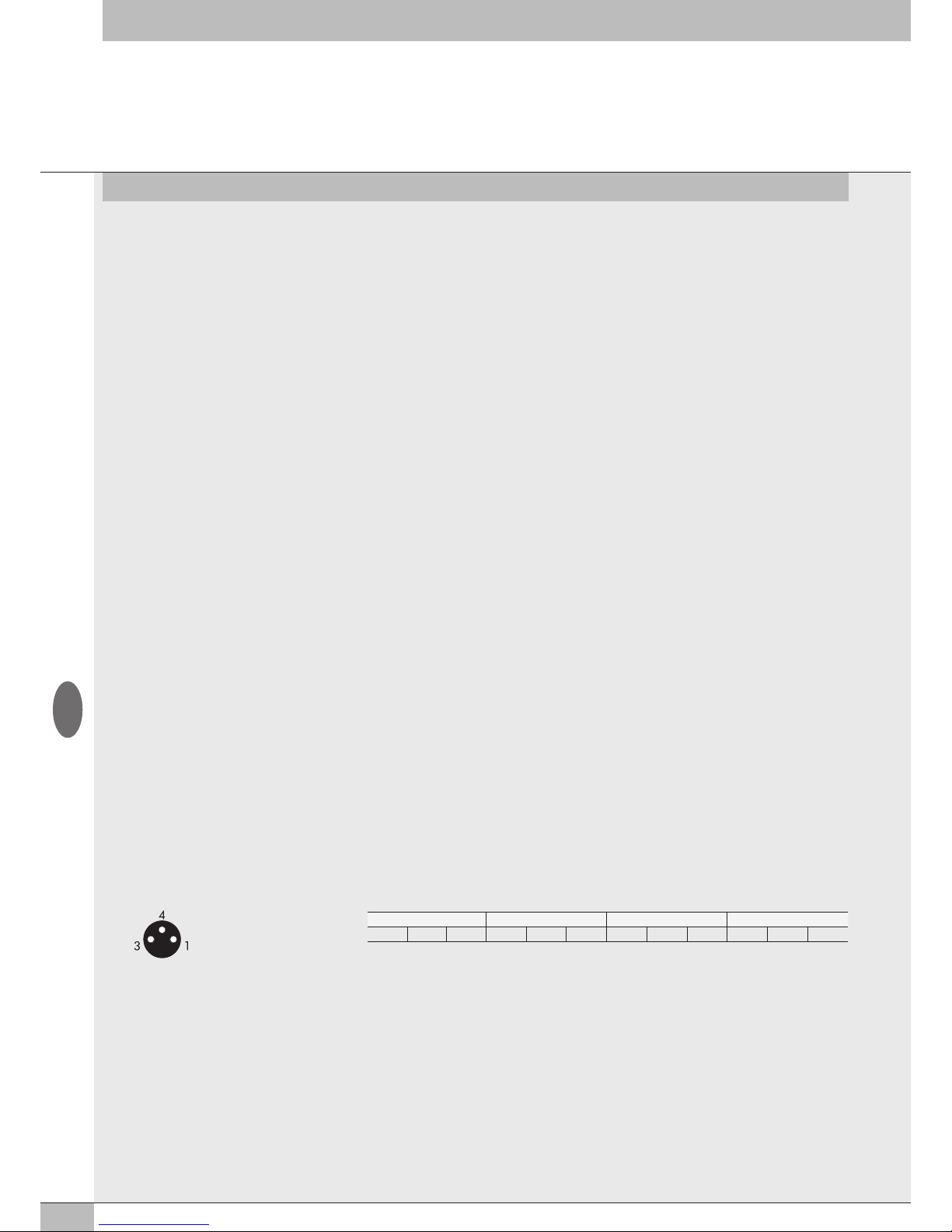
Piedinatura connettore M8 Piedinatura connettore morsettiera
3.3.1.3 Polarità - 0x8020 - Polarity DI8 e 0x8070 Polarity DI16
È possibile selezionare la polarità di ogni singolo ingresso . La polarità si definisce con l’oggetto 8020:0 Params_DI_Polarity.
Sono presenti 16 SubIndex corrispondenti ai 16 Moduli S installabili nel sistema.
• 0x8020:xx = 0 PNP, il segnale è attivo quando il pin di segnale è collegato al +VDC.
• 0x8020:xx = 1 NPN, il segnale è attivo quando il pin di segnale collegato allo 0VDC.
Il Led di segnalazione è attivo quando l’ingresso è attivo.
Esempio di configurazione del primo Modulo S collegato, con 8 ingressi NPN: 8020:01 SubIndex 001 = 255 (0xFF)
Esempio di configurazione del terzo Modulo S collegato, con i primi 4 ingressi NPN e i successivi 4 PNP: 8020:03 SubIndex 003 = 15 (0x0F).
1 = +VDC (Alimentazione sensore)
3 = GND (Alimentazione sensore)
4 = Input
Input X1 - X5 - X9 - X13 Input X2 - X6 - X10 - X14 Input X3 - X7 - X11 - X15 Input X4 - X8 - X12 - X16
+ Input 0 + Input 0 + Input 0 + Input 0
Alimentazione sensore
I
Page 12
12
3.3.1.4 Stato di attivazione 0x8021 - Activation state DI8 - 0x8071 Activation state DI16
È possibile selezionare lo stato di attivazione di ogni singolo ingresso. Lo stato di attivazione si definisce con l’oggetto
8021:0 Params_DI_ActStatus. Sono presenti 16 SubIndex corrispondenti ai 16 Moduli S installabili nel sistema.
• 0x8021:xx = 0 Normalmente Aperto, il segnale è attivo quando il sensore è attivo. Il Led è attivo quando il sensore è attivo.
• 0x8021:xx = 1 Normalmente Chiuso, il segnale è attivo quando il sensore è disattivo. Il Led è attivo quando il sensore è disattivo.
Esempio di configurazione del primo Modulo S collegato, con 8 ingressi NC: 8021:01 SubIndex 001 = 255 (0xFF)
Esempio di configurazione del terzo Modulo S collegato, con i primi 4 ingressi NC e i successivi 4 NO: 8020:03 SubIndex 003 = 15 (0x0F)
3.3.1.5 Persistenza del segnale 0x8022 - Signal extension DI8 - 0x8072 Signal extension DI16
La funzione consente di mantenere il segnale di ingresso per un tempo minimo corrispondente al valore impostato, consentendo al PLC di
rilevare segnali con tempi di persistenza bassi. La persistenza del segnale si definisce con l’oggetto 8022:0 Params_DI_SignExt. Sono presenti
16 SubIndex corrispondenti ai 16 Moduli S installabili nel sistema. Ogni modulo è definito con 2 Byte, per un totale di 32 Byte.
• 0x8022:xx = 0 - 0 ms: filtro disattivo.
• 0x8022:xx = 1 - 15 ms: segnali con tempi di attivazione/disattivazione minori di 15 ms, vengono mantenuti attivi per 15 ms.
• 0x8022:xx = 2 - 50 ms: segnali con tempi di attivazione/disattivazione minori di 50 ms, vengono mantenuti attivi per 50 ms.
• 0x8022:xx = 3 - 100 ms: segnali con tempi di attivazione/disattivazione minori di 100 ms, vengono mantenuti attivi per 100 ms.
La persistenza del segnale si definisce con l’oggetto 8022:0 Params_DI_SignExt. Sono presenti 16 SubIndex corrispondenti ai 16 Moduli S
installabili nel sistema.
3.3.1.6 Filtro di Input 0x8023 - Debounce time DI8 - 0x8073 Debounce time DI16
È un filtro temporale impostabile singolarmente per ogni singolo ingresso, che consente di filtrare e NON rilevare segnali con durata inferiore
al tempo impostato. La funzione può essere utilizzata per evitare di rilevare falsi segnali. Il filtro di Input si definisce con l’oggetto 8023:0
Params_DI_DebTime. Sono presenti 16 SubIndex corrispondenti ai 16 Moduli S installabili nel sistema. Ogni modulo è definito con 2 Byte, per
un totale di 32 Byte.
• 0x8023:xx = 0 - 0 ms: filtro disattivo.
• 0x8023:xx = 1 - 3 ms: non vengono rilevati cambiamenti di stato del segnale inferiori a 3 ms.
• 0x8023:xx = 2 - 10 ms: non vengono rilevati cambiamenti di stato del segnale inferiori a 10 ms.
• 0x8023:xx = 3 - 20 ms: non vengono rilevati cambiamenti di stato del segnale inferiori a 20 ms.
3.3.2.3 Polarità 0x8030 - Polarity DO8 - 0x8080 Polarity DO16
È possibile selezionare la polarità di ogni singola uscita. La polarità si definisce con l’oggetto 8030:0 Params_DO8_Polarity. Sono presenti 16
SubIndex corrispondenti ai 16 Moduli S installabili nel sistema.
• 0x8030:xx = 0 - PNP, Quando l’uscita è attiva sul pin di segnale è presente il +VDC. Per alimentare un carico è necessario collegare l’altro
capo allo 0VDC.
• 0x8030:xx = 1 - NPN, Quando l’uscita è attiva sul pin di segnale è presente lo 0VDC. Per alimentare un carico è necessario collegare l’altro
capo al +VDC.
Esempio di configurazione del primo Modulo S collegato, con 8 uscite NPN: 8030:01 SubIndex 001 = 255 (0xFF)
Esempio di configurazione del terzo Modulo S collegato, con le prime 4 uscite NPN e le successive 4 PNP: 8030:03 SubIndex 003 = 15 (0x0F)
3.3.2.1 Tipo di uscita e alimentazione
Possono essere utilizzate per controllare diversi dispositivi digitali. I dispositivi compatibili comprendono:
• Solenoidi
• Contattori
• Indicatori
L’alimentazione delle uscite proviene dall’Alimentazione nodo EtherCAT o se presente, dal Modulo 6 Output digitali M8 + alimentazione
elettrica precedente (vedi paragrafo 3.3.3).
Verificare che le correnti di picco e continuative dei dispositivi collegati non superino quelle fornibili su ogni singolo connettore e quella
massima del modulo.
Se il modulo è collegato direttamente alla Connessione elettrica EtherCAT, l’alimentazione è comune all’alimentazione del nodo EtherCAT.
Per evitare danni permanenti al dispositivo, è necessario inserire una adeguata protezione esterna.
3.3.2.2 Collegamenti elettrici
Piedinatura connettore M8 Piedinatura connettore morsettiera
3.3.2 Modulo Output digitali
Ogni modulo 8 Output digitali M8 può gestire fino a 8 uscite digitali. É definito con 1 byte, iniziando dal byte Out 16.
Modulo morsettiera 16 Output digitali: ogni modulo può gestire fino a 16 uscite digitali. É definito con 2 byte, iniziando dal byte Out 87.
Ogni uscita dispone di alcuni parametri configurabili singolarmente, attraverso la funzione CoE – CAN over EtherCAT.
Output X1 - X5 - X9 - X13 Output X2 - X6 - X10 - X14 Output X3 - X7 - X11 - X15 Output X4 - X8 - X12 - X16
+ Output 0 + Output 0 + Output 0 + Output 0
1 = +VDC (Comune per OUT NPN)
3 = GND (Comune per OUT PNP)
4 = Output
I
Page 13
13
3.3.3.1 Alimentazione ausiliaria
La corrente erogata è la somma delle correnti erogate dal Modulo 6 Output digitali M8 più quella erogata da tutti i Moduli di Segnali
successivi, collegati prima di un altro eventuale Modulo 6 Output digitali M8 + Alimentazione elettrica.
La massima corrente erogabile dai moduli collegati dopo un Modulo 6 Output digitali M8 + Alimentazione elettrica è 4 A.
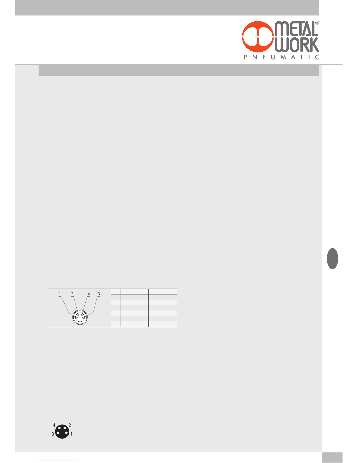
PIN Colore Funzione
1 Marrone +VDC
2 Bianco +VDC
3 Blu GND
4 Nero GND
3.3.3 Modulo 6 Output digitali M8 + alimentazione elettrica
Ogni modulo può gestire fino a 6 uscite digitali, è configurabile esattamente come il Modulo 8 Output digitali M8, attraverso gli oggetti 0x8040:0,
0x8041:0, 0x8042:0. E’ definito con 1 byte, iniziando dal byte Out 32.
Dispone di un connettore per l’alimentazione ausiliaria, che consente di aumentare la corrente fornibile dal modulo e dal sistema. Deve essere
inserito nel sistema, quando vengono installati più di un modulo di uscita. L’alimentazione ausiliaria di questo modulo alimenta anche tutti i moduli
Input / Output successivi. Il Modulo 6 Output digitali M8 + alimentazione elettrica, è provvisto di protezione da cortocircuito. Tutti i Moduli di
Segnali, successivi fruiscono della stessa protezione.
3.3.2.4 Stato di attivazione 0x8031 - Activation State DO8 - 0x8081 Activation State DO16
È possibile selezionare lo stato di attivazione di ogni singola uscita. Lo stato di attivazione si definisce con l’oggetto
8031:0 Params_DO8_ActStatus. Sono presenti 16 SubIndex corrispondenti ai 16 Moduli S installabili nel sistema.
• 0x8031:xx = 0 - Normalmente Aperto, l’uscita è attiva quando è comandata dal sistema di controllo. Il Led è attivo quando l’uscita è
comandata.
• 0x8031:xx = 1 - Normalmente Chiuso, l’uscita è attiva quando NON è comandata dal sistema di controllo. Il Led è attivo quando l’uscita
NON è comandata.
Esempio di configurazione del primo Modulo S collegato, con 8 uscite NC: 8031:01 SubIndex 001 = 255 (0xFF)
Esempio di configurazione del terzo Modulo S collegato, con le prime 4 uscite NC e le successive 4 NO: 8031:03 SubIndex 003 = 15 (0x0F)
3.3.2.5 Stato di sicurezza 0x8032 - Fail safe DO8 - 0x8082 Fail safe DO16
Questa funzione consente di definire lo stato delle uscite nel caso di comunicazione interrotta con il Master. Lo stato di sicurezza si definisce con
l’oggetto 0x8032:0 Params_DO8_FailSafe. Sono presenti 16 SubIndex corrispondenti ai 16 Moduli S installabili nel sistema.
• Output Reset (default), tutte le uscite vengono disattivate. Impostato con l’oggetto 0x8001:02 – Params_Head_ NetX
• Output Fault mode, 0x8032:xx. È possibile selezionare il comportamento di ogni singolo pilota tra tre modalità attraverso l’impostazione
dell’oggetto 0x8032:- Fail Safe.
L’oggetto è un array di 32 byte, e consente di configurare lo stato di di ogni pilota dei moduli pneumatici, riservando 2 bit per ogni canale.
- Valore = 0 Hold Last State, l’elettropilota mantiene lo stato in cui si trovava prima dell’interruzione della comunicazione con il Master.
- Valore = 1 Output Reset (default), l’elettropilota viene disattivato.
- Valore = 2 Output Set, al momento dell’interruzione della comunicazione con il Master l’elettropilota viene attivato.
Esempio: vedi esempio al par. 2.5.3
Al ripristino della comunicazione, la gestione dello stato degli elettropiloti viene ripreso dal Master.
Per evitare movimenti incontrollati, il Master deve provvedere ad una adeguata gestione dell’evento.
3.3.2.6 Guasti e allarmi
Il modulo è protetto da sovraccarichi e da cortocircuito su ogni singola uscita. Il reset della segnalazione è automatico. L’uscita viene comandata
brevemente ogni 30 sec per verificare che il guasto sia stato rimosso ed effettuare il reset automatico.
Per evitare movimenti incontrollati, il Master deve provvedere ad una adeguata gestione dell’evento.
3.3.4 Modulo 4 Input analogici M8
Ogni modulo può gestire fino a 4 ingressi analogici liberamente configurabili sia in tensione che in corrente.
Ogni ingresso è definito con 2 byte, iniziando dal byte In 17.
Converte i segnali con una risoluzione di 15 bit più il segno, i valori numerici disponibili al sistema di controllo, sono compresi tra –32768 e
+32767.
Dispongono di alcuni parametri configurabili singolarmente.
Il Modulo è in grado di riconoscere valori fuori range e nel caso di sensori 4/20 mA oppure 1/5 V la disconnessione del sensore stesso, dovuta
per esempio alla rottura del cavo. La segnalazione visiva di allarme e il relativo codice di errore sono descritti ai paragrafi 4.1 e 4.3.3.
3.3.4.1 Collegamenti elettrici: piedinatura connettore M8
Il valore della tensione di alimentazione +V è corrispondente alla tensione di Alimentazione nodo EtherCAT o della Connessione elettrica
Addizionale.
1 = +V
2 = + Analog IN
3 = GND
4 = - Analog IN
Ghiera connettore = Schermo
I
Page 14
14
3.3.4.2 Range Segnale 0x8050 - Signal range AI
Consente di configurare ogni singolo canale con un tipo di segnale di ingresso. L’oggetto 0x8050 è un array di 8 byte. Ogni ingresso è definito
con 4 bit, per un totale di 2 Byte per modulo.
Sono disponibili le seguenti tipologie:
• 0x8050:xx = 0 OFF
• 0x8050:xx = 1 0..10 Vdc
• 0x8050:xx = 2 - 10/+10 Vdc
• 0x8050:xx = 3 0…5 Vdc
• 0x8050:xx = 4 -5 / +5 Vdc
• 0x8050:xx = 5 1…5 Vdc
• 0x8050:xx = 6 0…20 mA
• 0x8050:xx = 7 4…20 mA
• 0x8050:xx = 8 -20 / + 20 mA
Se il canale non viene utilizzato, per evitare disturbi, disattivarlo selezionando OFF.
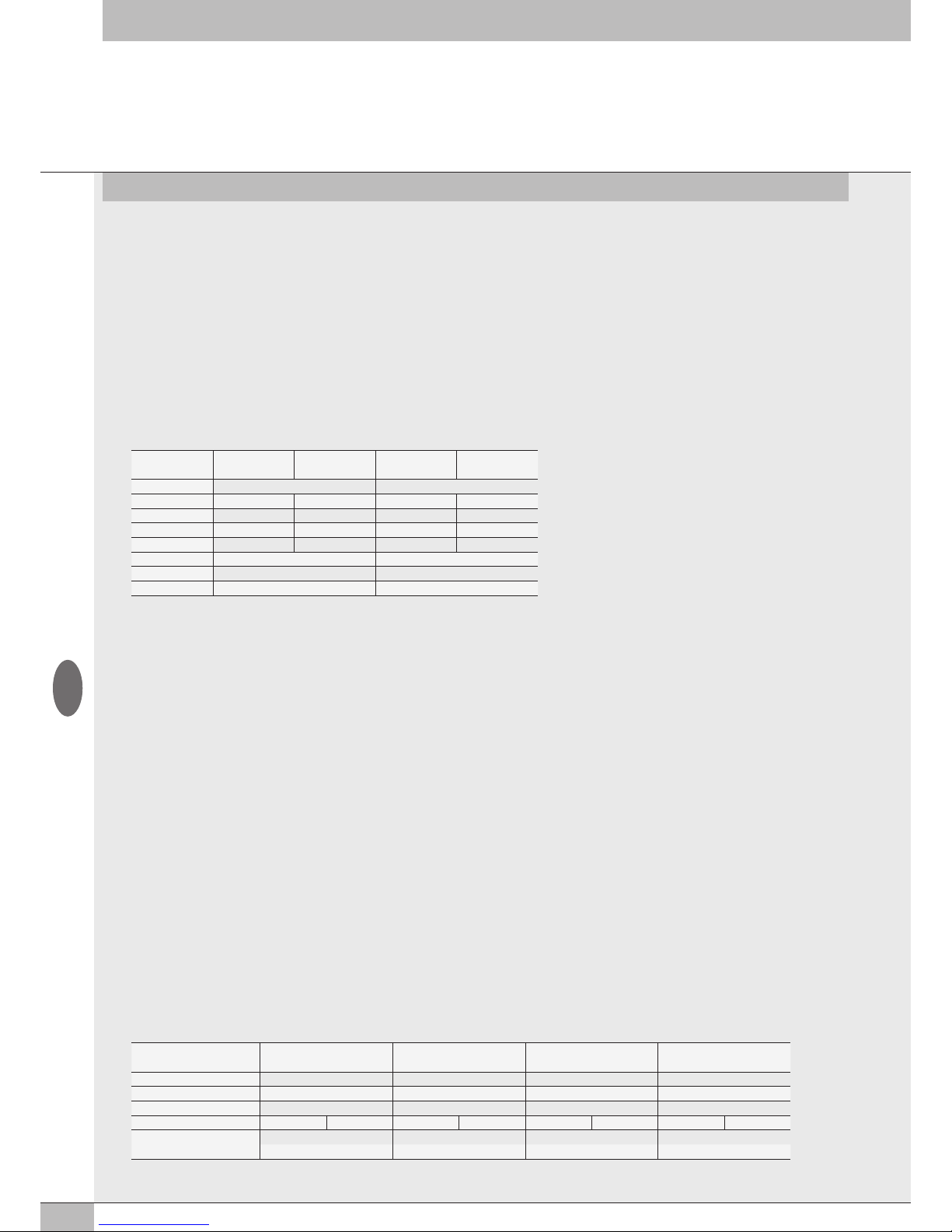
Esempio: primo modulo, gli ingressi X1 e X2 sono configurati 0..10 Vdc, gli ingressi X3 e X4 sono configurati 4…20 mA
N° ingresso X4 X3 X2 X1
Byte 2 1
bit 7 - 4 3 - 0 7 - 4 3 - 0
Range segnale 4…20 mA 4…20 mA 0..10 Vdc 0..10 Vdc
Valore 7 7 1 1
bit 0111 0111 0001 0001
Byte 01110111 00010001
Hex 77 11
Impostazioni 0x8050:02 = 77 0x8050:01 = 11
N° ingresso X4 X3 X2 X1
Byte 7 - 8 5 - 6 3 - 4 1 - 2
Fondo Scala 26500 26500 10000 10000
Valore hex 6784 6784 2710 2710
Impostazioni Byte 67 84 67 84 27 10 27 10
Impostazioni
0x8052:03 = 27 0x8052:05 = 67 0x8052:03 = 27 0x8052:01 = 27
0x8052:04 = 10 0x8052:06 = 84 0x8052:04 = 10 0x8052:02 = 10
Nota: l’esempio si basa su logica Motorola (parametro 0x8001:4 =0 Big Endian)
3.3.4.3 Filtro valore misurato 0x8051 - Filter measured value AI
Introduce un filtro sul valore misurato, per rendere più stabile la lettura. Viene effettuata una media mobile calcolata sul numero di campioni
scelto. Aumentando il numero di valori si rallenta la lettura. L’oggetto 0x8050 è un array di 8 byte. Ogni ingresso è definito con 4 bit, per un
totale di 2 Byte per modulo.
Sono disponibili i seguenti valori:
• 0x8051:xx = 0 Nessun filtro
• 0x8051:xx = 1 2 valori
• 0x8051:xx = 2 4 valori
• 0x8051:xx = 3 8 valori
• 0x8051:xx = 4 16 valori
• 0x8051:xx = 5 32 valori
• 0x8051:xx = 6 64 valori
Esempio: vedi tabella range segnale capitolo 3.3.4.2
3.3.4.4 Fondo Scala utente 0x8052 - User full scale AI
L’impostazione di questo valore consente di modificare la scala dei valori numerici inviati al sistema di controllo in funzione del valore del
segnale analogico. Deve essere abilitato impostando l’oggetto 0x8001:05 =1 Linear scaled.
Consente di impostare valori fino a 27531 per i canali in tensione e 27566 per i canali in corrente. Il valore impostato vale sia per i segnali
positivi che per quelli negativi. Ovvero se il range di segnale è impostato per esempio 0/10V il valore massimo sarà 27531.
Se il range di segnale è impostato +/- 10V i valori massimi saranno +27531 e -27531.
L’impostazione di valori superiori genera una segnalazione di “Bus Error – Errore dei parametri di configurazione”.
Questa funzione consente di ottenere una lettura in formato ingegneristico. Ovvero se al canale analogico è collegato un trasduttore di
pressione 0/10 bar e il fondo scala utente è impostato a 10000, il valore del segnale è espresso in mbar. L’oggetto 0x8050 è un array di 8
byte. Ogni ingresso è definito con 16 bit, per un totale di 8 Byte per modulo.
Esempio: primo modulo, gli ingressi X1 e X2 sono configurati con fondo scala = 10000, gli ingressi X3 e X4 sono configurati con
fondo scala = 26500
I moduli successivi proseguono con la numerazione del sub index fino a 0x8052:20
Nota: l’esempio si basa su logica Motorola (parametro 0x8001:4 =0 Big Endian)
I
Page 15
15
N° ingresso X4 X3 X2 X1
Byte 2 1
bit 7 - 4 3 - 0 7 - 4 3 - 0
Range segnale 4…20 mA 4…20 mA 0..10 Vdc 0..10 Vdc
Valore 7 7 1 1
bit 0111 0111 0001 0001
Byte 01110111 00010001
Hex 77 11
Impostazioni 0x8060:02 = 77 0x8060:01 = 11
I moduli successivi proseguono con la numerazione del sub index fino a 0x8060:08
Nota: l’esempio si basa su logica Motorola (parametro 0x8001:4 =0 Big Endian)
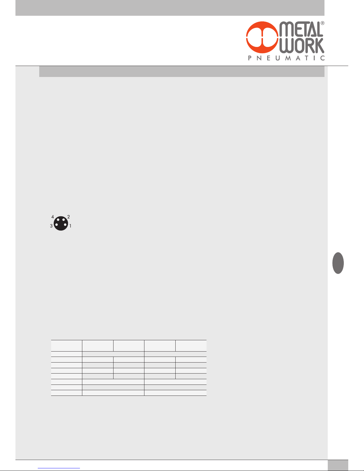
3.3.4.5 Collegamento dei sensori
3.3.5 Modulo 4 Output analogici M8
Ogni modulo può gestire fino a 4 uscite analogiche liberamente configurabili sia in tensione che in corrente.
Converte i segnali con una risoluzione di 15 bit più il segno, i valori numerici impostabili nel sistema di controllo, sono compresi tra –32768 e
+32767.
Dispongono di alcuni parametri configurabili singolarmente, disponibili selezionando il modulo nella “Vista generale Dispositivi
→
Proprietà →
Parametri dell’Unità".
3.3.5.1 Collegamenti elettrici: piedinatura connettore M8
Il valore della tensione di alimentazione +VDC è corrispondente alla tensione di Alimentazione nodo EtherCAT o della Connessione elettrica
Addizionale.
1 = +VDC
2 = + Analog OUT
3 = GND
4 = Shield
3.3.5.2 Range Segnale 0x8060 - Signal range AO
Consente di configurare ogni singolo canale con un tipo di segnale di uscita. L’oggetto 0x8060 è un array di 8 byte. Ogni uscita è definita con
4 bit, per un totale di 2 Byte per modulo.
Sono disponibili le seguenti tipologie:
• 0x8060:xx = 0 OFF
• 0x8060:xx = 1 0..10 Vdc
• 0x8060:xx = 2 - 10/+10 Vdc
• 0x8060:xx = 3 0…5 Vdc
• 0x8060:xx = 4 -5 / +5 Vdc
• 0x8060:xx = 6 0…20 mA
• 0x8060:xx = 7 4…20 mA
Se il canale non viene utilizzato, per evitare disturbi, disattivarlo selezionando OFF.
Esempio: primo modulo, le uscite X1 e X2 sono configurate 0..10 Vdc, le uscite X3 e X4 sono configurate 4…20 mA
Sensori in tensione a 3 fili
Pin 1 = +VDC Alimentazione sensore
Pin 2 = + Ingresso analogico
Pin 3 = GND
Pin 4 = NC
Sensori in tensione a 4 fili (differenziali)
Pin 1 = +VDC Alimentazione sensore
Pin 2 = + Ingresso analogico
Pin 3 = GND
Pin 4 = - Ingresso analogico
Sensori in corrente a 2 fili
Pin 1 = +VDC Alimentazione sensore
Pin 2 = + Ingresso analogico
Pin 3 = NC
Pin 4 = NC
Sensori in corrente a 3 fili
Pin 1 = +VDC Alimentazione sensore
Pin 2 = + Ingresso analogico
Pin 3 = GND
Pin 4 = NC
I
Page 16
16
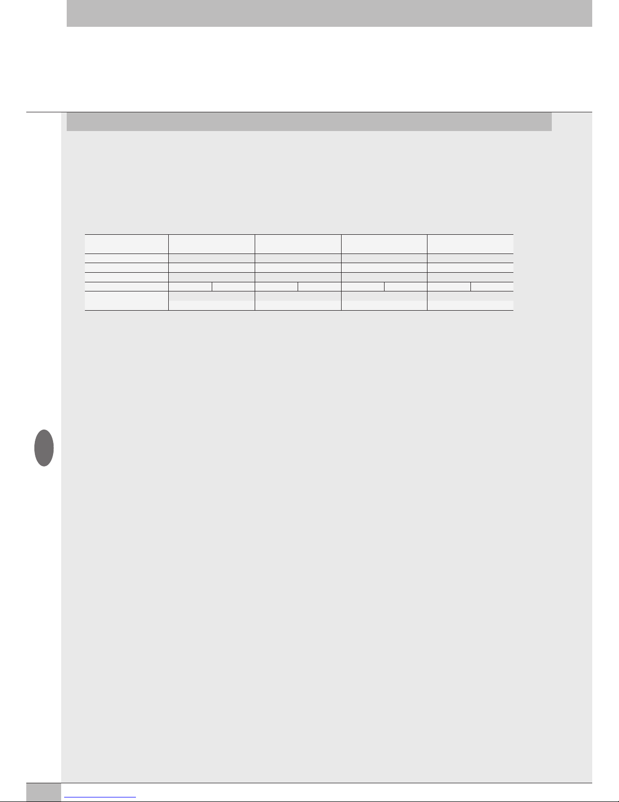
3.3.5.3 Fondo Scala utente 0x8061 - User full scale AO
L’impostazione di questi due valori consente di modificare la scala dei valori numerici inviati dal sistema di controllo per ottenere un valore del
segnale analogico in uscita.
Il sistema di conversione del segnale a 15 bit più il segno, consente di impostare valori da – 32768 a +32767.
In caso di necessità è possibile ridurre questi valori. L’oggetto 0x8061 è un array di 8 byte. Ogni ingresso è definito con 16 bit, per un totale di
8 Byte per modulo.
Esempio: primo modulo, le uscite X1 e X2 sono configurati con fondo scala = 10000, le uscite X3 e X4 sono configurati con fondo scala =
26500
I moduli successivi proseguono con la numerazione del sub index fino a 0x8052:20
Nota: l’esempio si basa su logica Motorola (parametro 0x8001:4 =0 Big Endian)
3.3.5.4 Monitor Minimo 0x8062 - Monitor lowest AO
L’oggetto è un array di 4 byte. Viene utilizzato per verificare che il valore ricevuto dal Master sia coerente con il valore impostato in Valore
Minimo 0x8064.
3.3.5.5 Monitor Massimo 0x8063 - Monitor Highest AO
L’oggetto è un array di 4 byte. Viene utilizzato per verificare che il valore ricevuto dal Master sia coerente con il valore impostato in Valore
Massimo 0x8065.
3.3.5.6 Valore minimo 0x8064 Lowest valve AO / Valore massimo 0x8065 Highest valve AO
Valori utilizzati per la funzione monitor.
Valore minimo 0x8064
L’oggetto è un array di 32 byte. Ogni uscita è definita con 2 Byte, per un totale di 8 Byte per modulo.
Consente di impostare valori fino a - 32768. Esempio: come tabella 3.3.5.3 Fondo Scala utente.
Valore massimo 0x8065
L’oggetto è un array di 32 byte. Ogni uscita è definita con 2 Byte, per un totale di 8 Byte per modulo.
Consente di impostare valori fino a + 32768. Esempio: come tabella 3.3.5.3 Fondo Scala utente.
3.3.5.7 Fail Safe Output 0x8066 - Fail Safe Output AO
Questa funzione consente di definire singolarmente il valore del segnale analogico di uscita nel caso di comunicazione interrotta con il Master.
Deve essere abilitata dall’oggetto 0x8001:02 =2. L’oggetto è un array di 4 byte. Ogni uscita è definita da 1 bit.
Esempio: primo modulo, l’ingresso X1 è configurato in modalità fail safe output , con il valore impostato in Fault mode value.
Gli ingressi X2, X3 e X4 sono configurati con Hold last state.
0x8066:01 = 01
3.3.5.8 Fault mode value 0x8067 - Fault mode value AO
Questa funzione consente di definire singolarmente il valore del segnale analogico di uscita nel caso di comunicazione interrotta con il Master.
L’oggetto è un array di 32 byte. Ogni uscita è definita con 2 Byte, per un totale di 8 Byte per modulo.
Esempio: come tabella 3.3.5.3 Fondo Scala utente
N° uscita X4 X3 X2 X1
Byte 7 - 8 5 - 6 3 - 4 1 - 2
Fondo Scala 32767 32767 10000 10000
Valore hex 7FFF 7FFF 2710 2710
Impostazioni Byte 7F FF 7F FF 27 10 27 10
Impostazioni
0x8061:07= 7F 0x8061:5 = 7F 0x8052:03 = 27 0x8052:01 = 27
0x8061:08 = FF 0x8061:6 = FF 0x8052:04 = 10 0x8052:02 = 10
I
Page 17
17
3.3.6 Modulo 4 input analogici M8 per la misura di Temperature
Ogni modulo S per la misura di temperature può gestire fino a 4 ingressi, liberamente configurabili per l’utilizzo di sensori di temperatura o di
termocoppie di vario tipo. Dispongono di alcuni parametri configurabili singolarmente.
La compensazione della temperatura (Cold Junction Compensation CJC) per l’utilizzo delle termocoppie è effettuata internamente, in condizioni
di temperatura ambiente normali non è necessario installare un giunto freddo esterno. L’installazione di un sensore esterno è consigliata in caso
di repentine variazioni della temperatura ambiente. Utilizzare un sensore PT1000 come per esempio il sensore TE Connectivity NB-PTCO-157 o
equivalente. Il modulo per la misura di temperatura trasmette al sistema di controllo i valori misurati, con 2 byte di ingresso per ogni canale.
Per un totale di 16 byte, per modulo iniziando dal byte IN 113.
Tipo di sensori supportati
Pt 100, Pt 200, Pt 500, Pt 1000
Ni 100, Ni 120, Ni 500, Ni 1000
Tipo di connessione a 2, 3, 4 fili
Tipo di termocoppie supportate
J, E, T, K, N, S, B, R
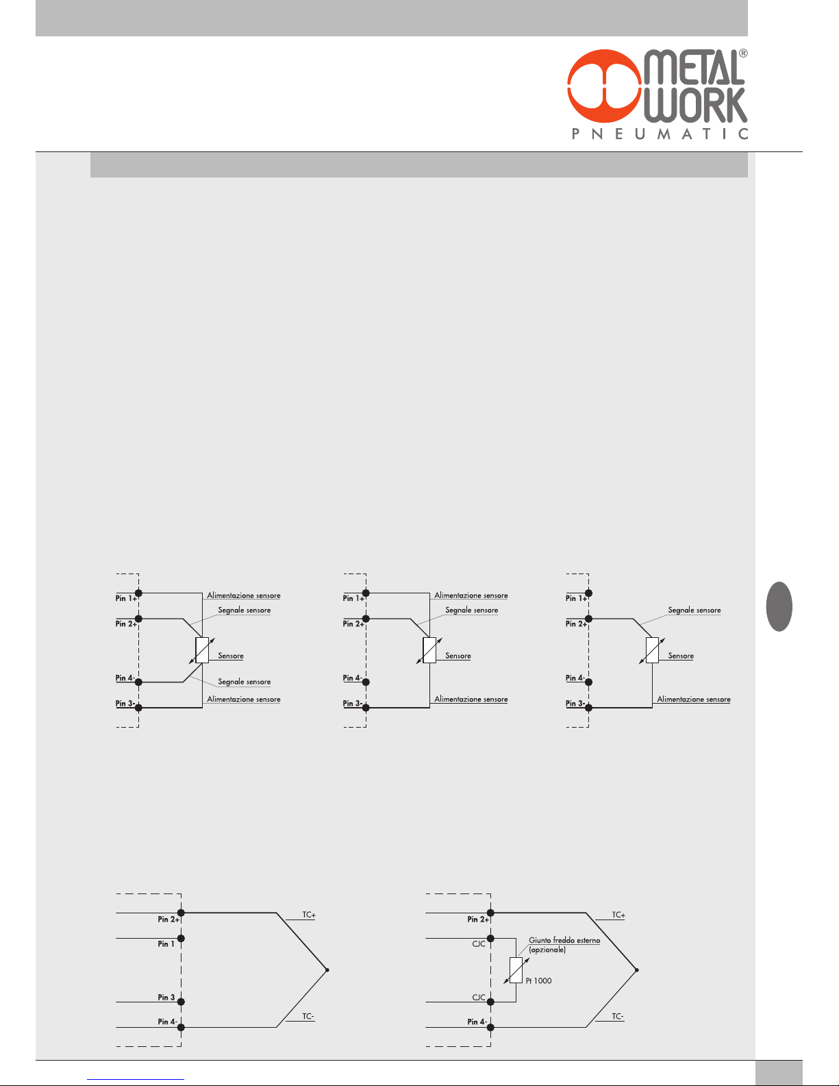
3.3.6.2 Connessioni elettriche delle termocoppie
Pin 1 = CJC Compensazione del giunto freddo tramite sensore esterno Pt1000 (opzionale)
Pin 2 = V+ Segnale di ingresso dal sensore
Pin 3 = CJC Compensazione del giunto freddo tramite sensore esterno Pt1000 (opzionale)
Pin 4 = V- Segnale di ingresso dal sensore
Ghiera= Messa a terra funzionale
Collegamento standard – giunto freddo interno Collegamento con giunto freddo esterno - Opzionale
3.3.6.1 Connessioni elettriche dei sensori di temperatura (serie Pt e Ni)
Pin 1 = + Alimentazione Sensore
Pin 2 = + Segnale in ingresso, positivo
Pin 3 = - Alimentazione Sensore
Pin 4 = - Segnale di ingresso, negativo
Ghiera = Messa a terra funzionale
Ogni ingresso mette a disposizione due Pin per l’alimentazione costante del sensore e due pin per la misura del segnale.
È possibile realizzare collegamenti a 2, 3, 4 fili a seconda della precisione desiderata.
La massima precisione si ottiene con il collegamento a 4 fili.
Connessione a 4 fili Connessione a 3 fili Connessione a 2 fili
In generale per la trasmissione dei segnali analogici è consentito esclusivamente l’utilizzo di cavi schermati.
I
Page 18
18
3.3.6.3 Parametri dell’unità
Parametri comuni
• Unità di misura da 0x8090.01a 0x80A3.01 Unit of measure: è possibile selezionare la temperatura letta in °Celsius oppure in °Fahrenheit
0x8090.01 = 0 °Celsius
0x8090.01 = 1 °Fahrenheit
• Soppressione del rumore da 0x8090.02 a 0x80A3.02 Noise rejection: consente di sopprimere il rumore elettrico generato dalla rete di
alimentazione. Lavora in combinazione con il parametro “Filtro di acquisizione”.
0x8090.02 = 0 50 Hz: sopprime i disturbi generati da una rete elettrica a 50 Hz
0x8090.02 = 1 60 Hz: sopprime i disturbi generati da una rete elettrica a 60 Hz
0x8090.02 = 2 50/60 Hz slow: sopprime i disturbi generati da una rete elettrica a 50 e 60 Hz.
Si ottiene un filtraggio alto, ma con un ritardo nell’acquisizione del dato.
0x8090.02 = 3 50/60 Hz fast: sopprime i disturbi generati da una rete elettrica a 50 e 60 Hz.
Si ottiene un’acquisizione del dato rapida ma un filtraggio basso.
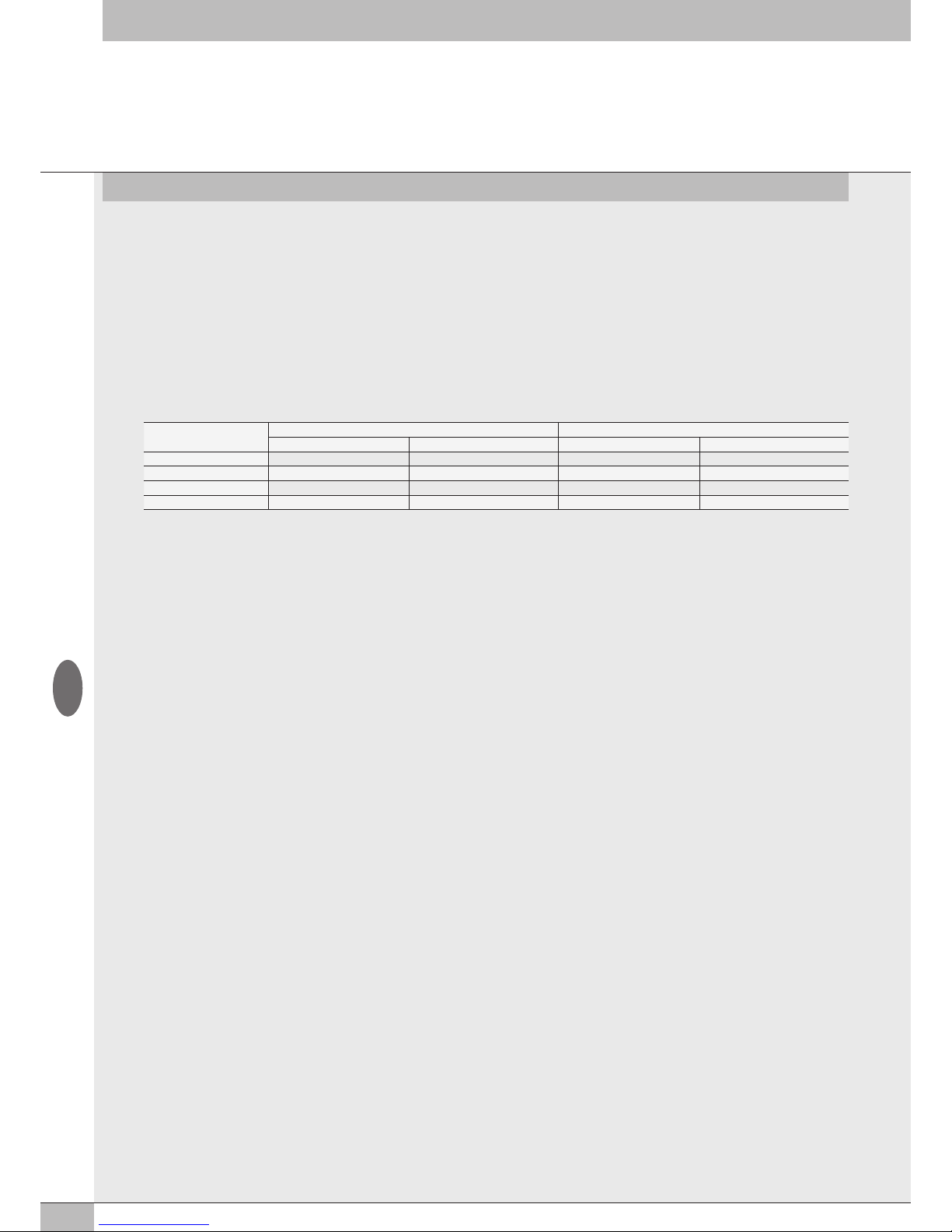
Soppressione del rumore
Sync 3 Sync 4
Attenuazione (dB) Ritardo Acquisizione dato (ms) Attenuazione (dB) Ritardo Acquisizione dato (ms)
50 Hz 95 60 120 80
60 Hz 95 50 120 67
50/60 Hz Slow 100 300 120 400
50/60 Hz Fast 67 60 82 80
Input Canale
• Tipo di sensore da 0x8094.01 a 0x80A3.01 Sensor adjustment: è possibile selezionare il tipo di sensore utilizzato, tra quelli supportati.
0x8094.01 = 0 Nessun sensore connesso
0x8094.01 = 1 Pt 100 (TK=0.00385)
0x8094.01 = 2 Pt 200 (TK=0.00385)
0x8094.01 = 3 Pt 500 (TK=0.00385)
0x8094.01 = 4 Pt 1000 (TK=0.00385)
0x8094.01 = 5 Pt 100 (TK=0.00391)
0x8094.01 = 6 Pt 200 (TK=0.00391)
0x8094.01 = 7 Pt 500 (TK=0.00391)
0x8094.01 = 8 Pt 1000 (TK=0.00391)
0x8094.01 = 9 Ni 100 (TK=0.00617)
0x8094.01 = 0A Ni 200 (TK=0.00617)
0x8094.01 = 0B Ni 500 (TK=0.00617)
0x8094.01 = 0C Ni 1000 (TK=0.00617)
0x8094.01 = 0D TC Type E
0x8094.01 = 0E TC Type J
0x8094.01 = 0F TC Type T
0x8094.01 = 10 TC Type K
0x8094.01 = 11 TC Type N
0x8094.01 = 12 TC Type S
0x8094.01 = 13 TC Type B
0x8094.01 = 14 TC Type R
• Tipo di collegamento (solo per RTD) da 0x8094.02 a 0x80A3.02 Connection technology: è possibile selezionare il tipo di collegamento del
sensore, se a 2, 3 o 4 fili.
0x8094.02 = 0 2 fili
0x8094.02 = 1 3 fili
0x8094.02 = 2 4 fili
• Compensazione giunto freddo (solo per TC) da 0x8094.03 a 0x80 A3.03 Cold junction compensation: consente di selezionare l’utilizzo di
un giunto freddo esterno al posto di quello già montato internamente. Il giunto freddo esterno (Pt1000) è consigliato in caso di repentine
variazioni della temperatura ambiente.
0x8094.03 = 0 interna
0x8094.03 = 1 esterna
• Risoluzione della misura da 0x8094.04 a 0x80A3.04 Measure resolution: consente di impostare la risoluzione della misura in decimi o in
centesimi di °C. La risoluzione in centesimi è solo per i sensori RTD e consente la lettura di una temperatura massima di +/- 327 °C.
0x8094.04 = 0 0.1
0x8094.04 = 1 0.01
• Segnalazione sensore disconnesso da 0x8094.05 a 0x80A3.05 Signaling disconnected sensor: se abilitato, la rottura di un filo collegamento
genera un allarme.
0x8094.05 = 0 Disabilitato
0x8094.05 = 1 Abilitato
I
Page 19

19
• Segnalazione corto circuito (solo per RTD) da 0x8094.06 a 0x80A3.06 Short circuit signaling: se abilitato, un corto circuito del
collegamento del sensore genera un allarme.
0x8094.06 = 0 Disabilitato
0x8094.06 = 1 Abilitato
• Monitor Valore minimo da 0x8094.07 a 0x80A3.07 Lowest value: l’abilitazione di questa funzione consente di generare un allarme nel
caso la temperatura sia inferiore al valore impostato in Valore minimo.
0x8094.07 = 0 Disabilitato
0x8094.07 = 1 Abilitato
• Monitor Valore massimo da 0x8094.08 a 0x80A3.08 Highest value: l’abilitazione di questa funzione consente di generare un allarme nel
caso la temperatura sia superiore al valore impostato in Valore Massimo.
0x8094.08 = 0 Disabilitato
0x8094.08 = 1 Abilitato
• Filtro Valore Misurato da 0x8094.09 a 0x80A3.09 Filter measured value: è un filtro matematico che consente di ottenere una lettura della
temperatura più stabile. Impostando un valore di filtro sul campionamento del segnale più alto si ottiene una maggiore stabilità di lettura ma
un ritardo maggiore nella visualizzazione del dato.
0x8094.09 = 1 1 Campione
0x8094.09 = 2 2 Campioni
0x8094.09 = 3 4 Campioni
0x8094.09 = 4 8 Campioni
0x8094.09 = 5 16 Campioni
0x8094.09 = 5 32 Campioni
0x8094.09 = 6 64 Campioni
• Valore Minimo da 0x8094.0A a 0x80A3.0A Lowest value
• Valore massimo da 0x8094.0B a 0x80A3.0B Highest value
• Filtro di Acquisizione da 0x8094.0C a 0x80A3.0C Acquisition filter: definisce il tipo di filtro digitale.
Lavora in combinazione con il parametro “Soppressione del rumore”.
Impostando Sync 4 si ottiene un filtraggio più alto rispetto a Sync 3, ma con un ritardo maggiore nell’acquisizione del dato.
0x8094.0C = 0 Sync3
0x8094.0C = 1 Sync4
I
Page 20
20
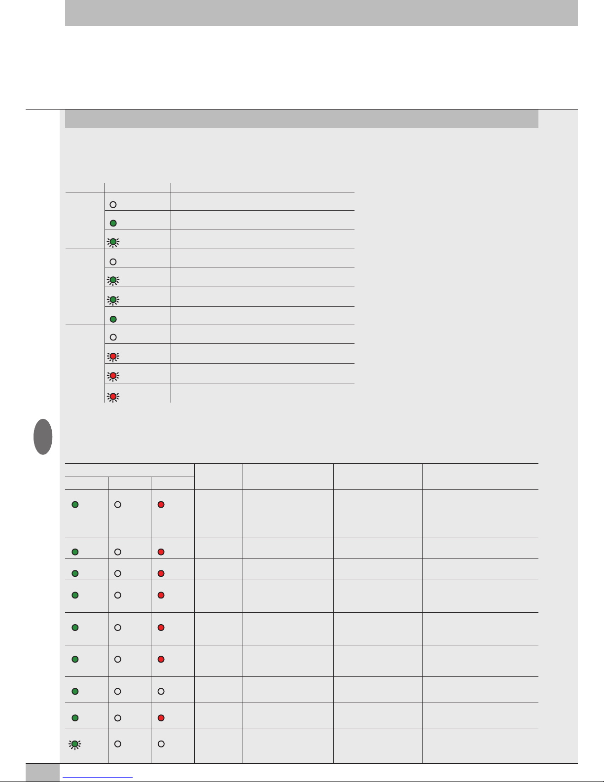
La diagnostica del sistema EB 80 EtherCAT, è definita dallo stato dei Led di interfaccia.
Ogni componente del sistema segnala il suo stato, localmente tramite Led e al nodo EtherCAT tramite messaggi software.
4.1 DIAGNOSTICA DEL NODO EtherCAT
La diagnostica del nodo EtherCAT è definita dallo stato dei Led RUN, ERR e IN/OUT.
4. DIAGNOSTICA
Led STATO Significato
IN / OUT
link/act
OFF
Nessuna connessione alla rete EtherCAT
ON (verde)
Il
dispositivo
è connesso alla rete ma non c’è scambio di dati
VERDE Il dispositivo comunica correttamente con la rete
(lampeggiante)
RUN
OFF
Il dispositivo è nello stato INIT
VERDE Il dispositivo è nello stato PRE-OPERATIONAL
(lampeggiante)
VERDE Il dispositivo è nello stato SAFE-OPERATIONAL
(singolo lampeggio)
VERDE Il dispositivo è nello stato OPERATIONAL
ERR
OFF Nessun errore il dispositivo funziona correttamente
ON (rosso) Errore di configurazione
(lampeggiante)
ON (rosso) Errore di watch dog.
(singolo lampeggio)
ON (rosso) Errore di comunicazione, cavo scollegato
(doppio lampeggio)
I
4.2 DIAGNOSTICA DEL SISTEMA EB 80 – CONNESSIONE ELETTRICA
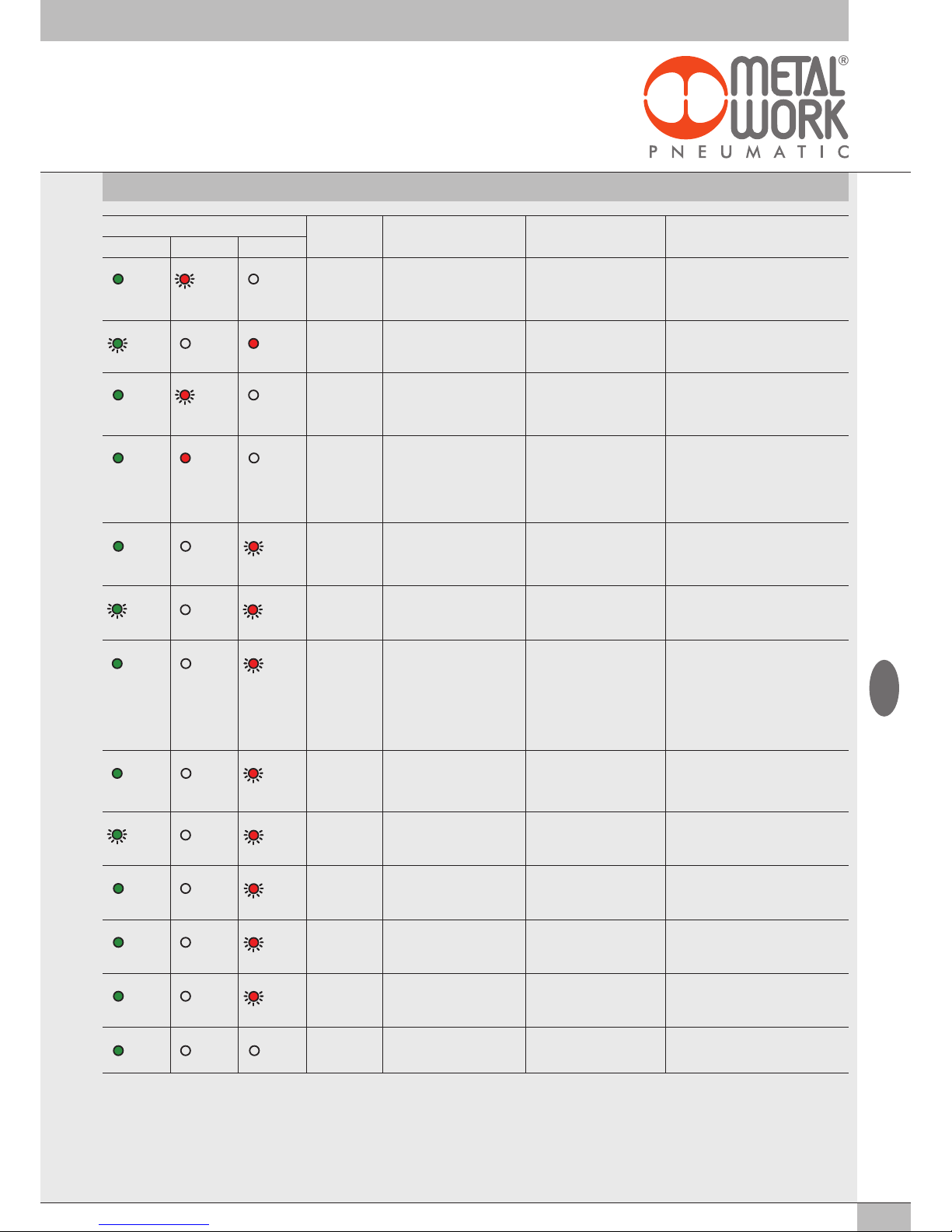
La diagnostica sistema EB 80 - Connessione elettrica - è definita dallo stato dei Led Power, Bus Error e Local Error.
Le funzioni di diagnostica del sistema EB 80, restituiscono al controllore, in ordine di priorità, lo stato del sistema tramite dei codici di errore in
formato esadecimale o binario. Il byte di stato viene interpretato dal controllore come un byte di input. La corretta interpretazione dei codici è
descritta nella tabella seguente:
Stato dei Led Codice Hex Significato Note Soluzione
Power Bus Error Local Error
ON (verde) OFF ON (rosso)
0xFF
Limiti di sistema superati,
overflow di dati sulla linea di
comunicazione.
Il numero di ingressi
uscite da controllare
contemporaneamente è troppo
elevato o la frequenza di
comando è troppo elevata.
Modificare il sistema riducendo Il
numero di ingressi uscite da controllare
contemporaneamente.
Contattare l’assistenza tecnica
ON (verde) OFF ON (rosso)
0xD4 ÷ 0xD7
Guasto di un modulo per
misura temperature
• Sensore non connesso
• Parametri errati
Verificare la connessione e i parametri
impostati
ON (verde) OFF ON (rosso)
0xD0 ÷ 0xD3
Modulo input analogico non
calibrato
- Contattare l’assistenza tecnica
ON (verde) OFF ON (rosso)
0xCC ÷ 0xCF
Guasto di un output analogico
o corrente totale del modulo
troppo elevata
Singolo output guasto /
sovra-assorbimento del
modulo / errori DAC
Togliere l’alimentazione elettrica e
rimuovere la causa del guasto
ON (verde) OFF ON (rosso)
0xC8 ÷ 0xCB
Guasto di un input analogico
o corrente totale del modulo
troppo elevata
under-overflow o fuori range
singolo input / sovra-assorbimento del modulo
Togliere l’alimentazione elettrica e
rimuovere la causa del guasto
ON (verde) OFF ON (rosso)
0xB0 ÷ 0xC5
Guasto di un output digitale
o corrente totale del modulo
troppo elevata
Corto circuito di un singolo
output / sovra-assorbimento
del modulo
Togliere l’alimentazione elettrica e
rimuovere la causa del guasto
ON (verde) OFF OFF
0xA0 ÷ 0xAF
Sovracorrente di un input
digitale
Segnalato dal singolo input Togliere l’alimentazione elettrica e
rimuovere la causa del guasto
ON (verde) OFF ON (rosso)
0x20 ÷ 0x9F
Valvola 1 / 128 guasta
**
Elettropilota in cortocircuito,
interrotto o non collegato
Togliere l’alimentazione elettrica e
rimuovere la causa del guasto
VERDE
(lampeggiante)
OFF OFF
0x17
Mancanza alimentazione
ausiliaria
- Inserire l’alimentazione ausiliaria
Page 21
21
** Per individuare la posizione della valvola guasta procedere come segue:
Codice errore HEX – 0x20 = n
Trasformare il codice n da esadecimale a decimale, il numero ottenuto corrisponde alla posizione guasta.
Anche le posizioni dove vi siano montate False valvole o bypass devono essere conteggiate. I codici sono numerati da 0 a 127. Il codice 0 corrisponde alla prima valvola dell’isola.
Esempio: codice di errore 0x20 n= 0x20 – 0x20 = 0x00
valore decimale = 0 che corrisponde alla prima valvola (posizione) dell’isola.
Codice errore 0x3F n= 0x3F – 0x20 = 1F
valore decimale = 31 che corrisponde alla valvola (posizione) 32.
Stato dei Led Codice Hex Significato Note Soluzione
Power Bus Error Local Error
ON (verde) ROSSO
(doppio
lampeggio)
OFF
0x16
Errore indirizzo /
configurazione di una base per
valvole o di un modulo segnale
Base valvole o modulo segnale
difettoso
Togliere l’alimentazione elettrica e
rimuovere la causa del guasto
VERDE
(lampeggiante)
OFF ON (rosso)
0x15
Alimentazione fuori range
(Under/over-Voltage)
- Alimentare il sistema con una tensione
compresa nel range di funzionamento
ammesso
ON (verde) ROSSO
(singolo
lampeggio)
OFF
0x14
Errore nei parametri di
configurazione di una base per
valvole o di un modulo segnale
La configurazione attuale
non corrisponde a quella
memorizzata nel dispositivo.
Ripetere la procedura di configurazione.
Se l'errore persiste sostituire il
componente difettoso.
ON (verde) ON (rosso) OFF
0x10
Comunicazione interna EB 80
Net difettosa
Isola addizionale configurata
ma non collegata.
Connessione tra le basi valvola
difettosa o non terminata (il
terminale cieco C montato non
è del tipo per bus di campo).
Verificare la corretta connessione di tutto
il sistema. Verificare che il terminale
cieco sia del tipo per bus di campo.
Ripristinando la comunicazione,
l’allarme si resetta automaticamente
dopo 3 sec.
ON (verde) OFF ROSSO
(singolo
lampeggio)
0x09
Errore nei parametri di
configurazione della testa
Almeno un valore errato o
fuori range
-
VERDE
(lampeggiante)
OFF ROSSO
(lampeggiante)
0x08
Numero di piloti collegati alla
rete maggiore di 128
- Ripristinare una configurazione delle
basi per valvole corretta togliendo quelle
in eccesso.
ON (verde) OFF ROSSO
(doppio
lampeggio)
0x07
Errore di mappatura
Numero di Basi per valvole
collegate diverso da quello
impostato o superiore al
numero max ammesso;
Piastra di chiusura lato moduli
S non connessa.
La configurazione attuale
non corrisponde a quella
memorizzata nel dispositivo.
La rete EB 80 Net non è
correttamente terminata
Togliere l’alimentazione elettrica.
Ripristinare la configurazione corretta o
ripetere la procedura di configurazione.
Togliere l’alimentazione elettrica,
montare la piastra di chiusura con
l’apposita scheda di terminazione o
inserire il connettore di terminazione.
ON (verde) OFF ROSSO
(singolo
lampeggio)
0x06
Errore di indirizzamento:
• tipo di modulo non ammesso;
• nessuna Base per valvole o
modulo segnali collegato.
- Collegare delle basi per valvole o dei
moduli segnale di tipo ammesso.
VERDE
(lampeggiante)
OFF ROSSO
(lampeggiante)
0x05
Numero di input digitali
collegati alla rete maggiore
di 128
- Disconnettere i moduli in eccesso
ON (verde) OFF ROSSO
(lampeggiante)
0x04
Numero di output digitali
collegati alla rete maggiore
di 128
- Disconnettere i moduli in eccesso
ON (verde) OFF ROSSO
(lampeggiante)
0x03
Numero di input analogici
collegati alla rete maggiore
di 16
- Disconnettere i moduli in eccesso
ON (verde) OFF ROSSO
(lampeggiante)
0x02
Numero di output analogici
collegati alla rete maggiore
di 16
- Disconnettere i moduli in eccesso
ON (verde) OFF OFF
0x00
Il sistema funziona
correttamente
- -
I
Page 22
22
I
4.3 DIAGNOSTICA DEL SISTEMA EB 80 – BASE VALVOLE
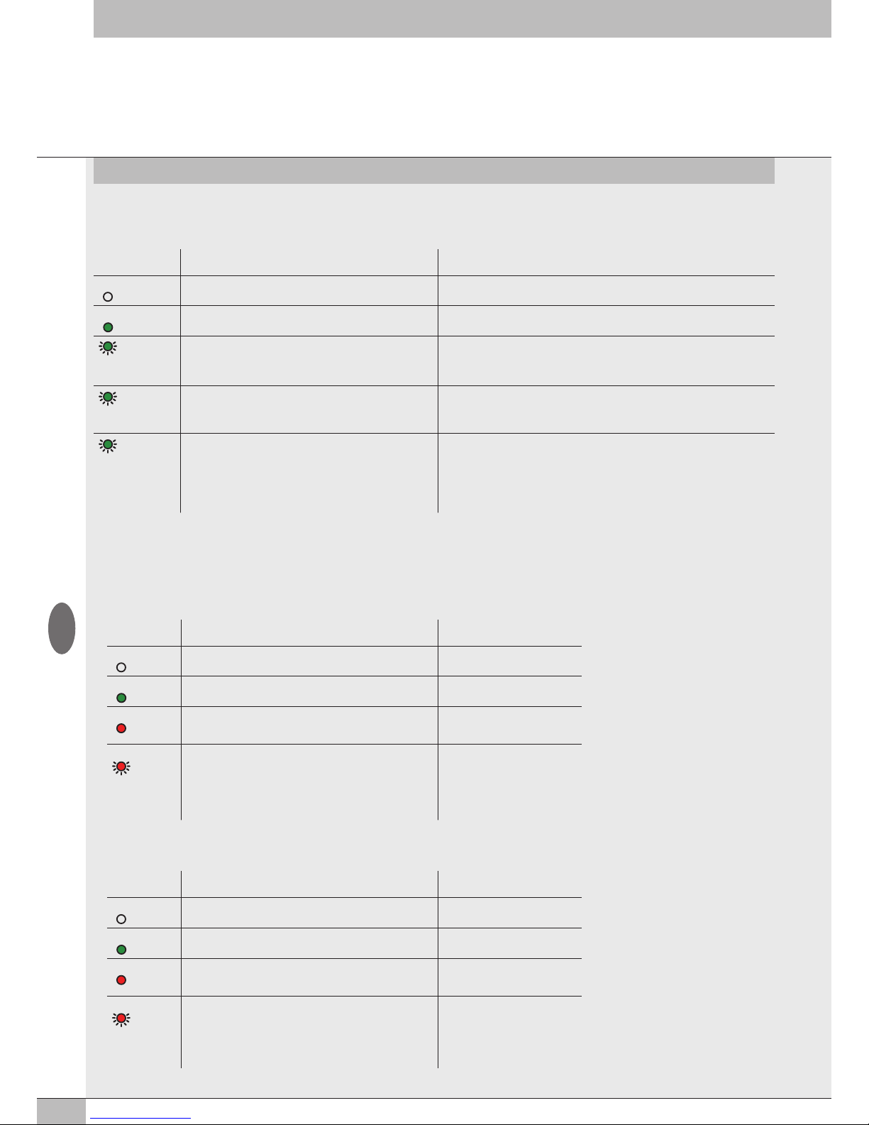
La diagnostica delle basi per valvole è definita dallo stato dei Led di interfaccia.
La generazione di un allarme attiva un messaggio software per la Connessione Elettrica con il codice relativo all’errore rilevato.
Led VERDE
BASE
Significato Stato dell’Out Segnalazione GUASTO e memorizzazione
OFF L’uscita non è comandata. Out Segnalazione GUASTO - OFF
ON L’uscita è attiva e funziona correttamente. Out Segnalazione GUASTO - OFF
(doppio lampeggio)
Segnalazione per ogni singola uscita.
Elettropilota interrotto o mancante (falsa valvola o valvola con
un elettropilota installata su una base per due elettropilota).
Out Segnalazione GUASTO – Attiva
L’uscita è Auto-ripristinante se la causa del guasto viene rimossa.
La segnalazione GUASTO è resettabile solo togliendo l’alimentazione elettrica.
(lampeggiante)
Segnalazione per ogni singola uscita Elettropilota o uscita
della base in cortocircuito.
Out Segnalazione GUASTO – Attiva permanente
L’uscita viene spenta.
Resettabile solo togliendo l’alimentazione elettrica.
(lampeggiante +
lampeggio
contemporaneo
di tutti i Led
della base)
Tensione di alimentazione fuori range
Minore di 10.8V o maggiore di 31.2V
Attenzione: una tensione maggiore di 32VDC danneggia
irreparabilmente il sistema.
Out Segnalazione GUASTO - Attiva
Auto-ripristinante rientrando nel range di funzionamento.
Le segnalazioni permangono 5 secondi dopo il rientro nel range di funzionamento.
4.4 DIAGNOSTICA DEL SISTEMA EB 80 – MODULI SEGNALI - S
La diagnostica dei Moduli di segnali - S è definita dallo stato dei Led di interfaccia.
La generazione di un allarme attiva un messaggio software per la Connessione Elettrica con il codice relativo all’errore rilevato.
4.4.1 Diagnostica dei Moduli segnali - S – Input Digitali
Led
X1..X8
Significato Soluzione
OFF L’ingresso non è attivo -
ON (verde) L’ingresso è attivo -
ON (rosso) Segnalazione per ogni singolo ingresso.
Ingresso in cortocircuito o sovraccarico.
Rimuovere la causa del guasto
ROSSO
(lampeggiante +
lampeggio
contemporaneo
di tutti i Led)
Assorbimento complessivo di corrente troppo elevato. Rimuovere la causa del guasto
4.4.2 Diagnostica dei Moduli segnali - S – Output Digitali
Led
X1..X8
Significato Soluzione
OFF L’uscita non è attiva -
ON (verde) L’uscita è attiva e funziona correttamente -
ON (rosso) Segnalazione per ogni singola uscita.
Uscita in cortocircuito o sovraccarico.
Rimuovere la causa del guasto
ROSSO
(lampeggiante +
lampeggio
contemporaneo
di tutti i Led)
Assorbimento complessivo di corrente troppo elevato. Rimuovere la causa del guasto
Page 23
23
I
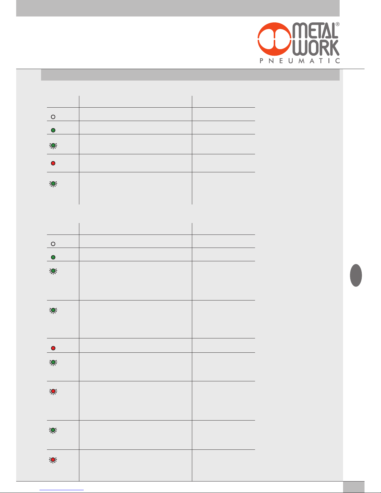
4.4.3 Diagnostica dei Moduli segnali - S – Input Analogici
Led
X1..X4
Significato Soluzione
OFF L’ingresso non è attivo -
ON (verde) L’ingresso è attivo e funziona correttamente -
VERDE
(lampeggiante)
Segnale analogico fuori dal range ammesso Impostare correttamente il tipo di
ingresso Sostituire il sensore con uno
di tipo ammesso
ON (rosso) Valore del segnale analogico troppo alto/basso Impostare correttamente il tipo di
ingresso Sostituire il sensore con uno
di tipo ammesso
VERDE
(lampeggio
contemporaneo
di tutti i Led
della base)
Segnalazione di cortocircuito o sovraccarico. Rimuovere la causa del guasto
4.4.4 Diagnostica dei Moduli segnali - S – Output Analogici
Led
X1..X4
Significato Soluzione
OFF L’uscita non è attiva -
ON (verde) L’uscita è attiva e funziona correttamente -
VERDE
(Lampeggio
contemporaneo
di tutti i Led
T ON 0.2 sec
T OFF 1 sec )
Valore della tensione di alimentazione fuori dal range ammesso Alimentare correttamente il modulo
VERDE
(Lampeggio
contemporaneo
di tutti i Led
T ON 0.2 sec
T OFF 0.2 sec)
Segnalazione di cortocircuito o sovraccarico sull’alimentazione. Rimuovere la causa del guasto
ON (rosso) Tutti i led attivi contemporaneamente.
Guasto interno
Sostituire il modulo
VERDE
(Lampeggio
T ON 0.6 sec
T OFF 0.6 sec)
Uscita in sovraccarico o in corto circuito Rimuovere la causa del guasto.
Togliere l’alimentazione elettrica per
resettare la segnalazione di guasto.
ROSSO
(Lampeggio
contemporaneo
di tutti i Led
T ON 0.2 sec
T OFF 0.2 sec)
Sovratemperatura del modulo Rimuovere la causa del guasto.
VERDE
(Doppio Lampeggio
T ON 0.6 sec
T OFF 1 sec )
Segnalazione circuito aperto. (Per canali 4/20 mA o 1/5 V) Rimuovere la causa del guasto.
ROSSO
(Lampeggio
T ON 0.6 sec
T OFF 0.6 sec)
Valore impostato non ammesso Rimuovere la causa del guasto.
Togliere l’alimentazione elettrica per
resettare la segnalazione di guasto.
Page 24
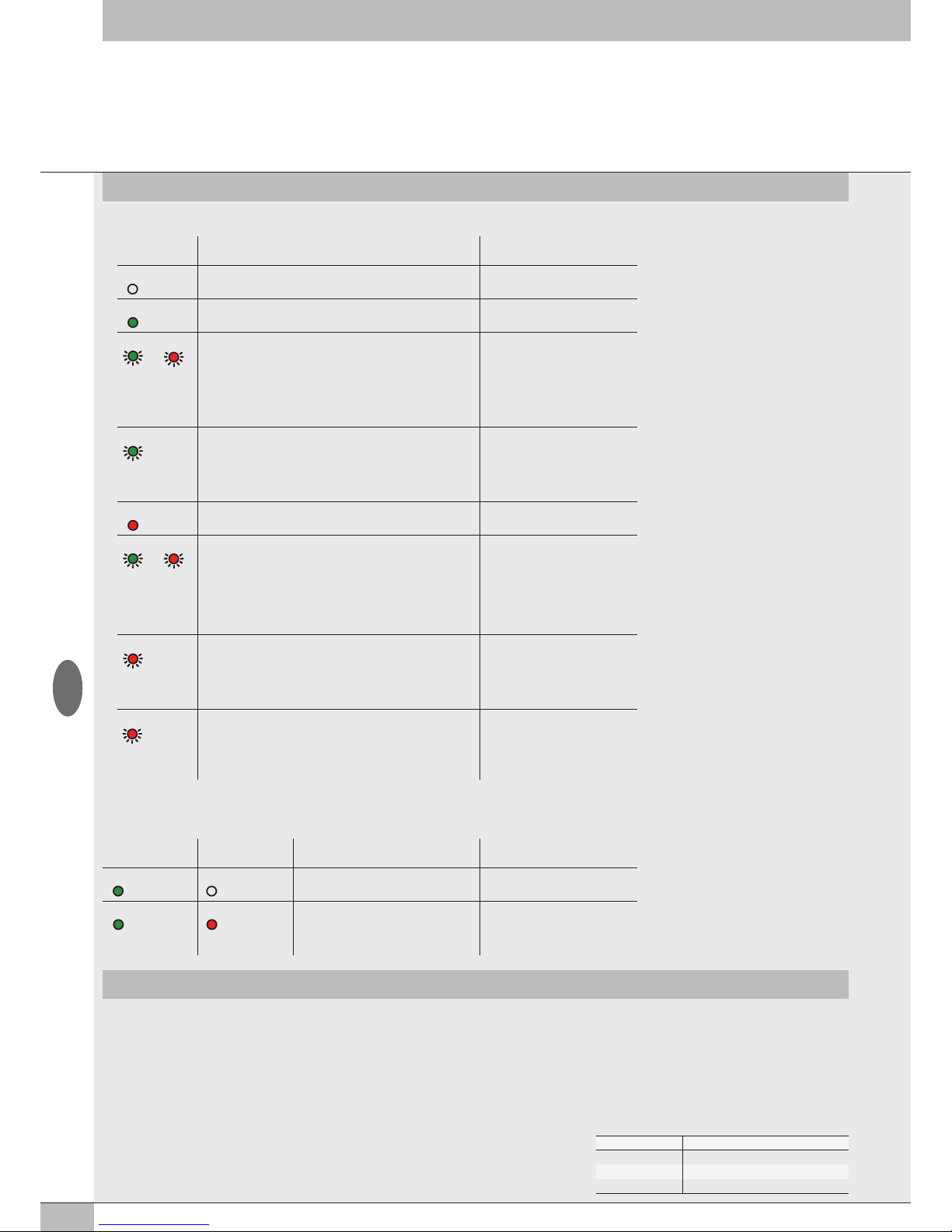
24
5. LIMITI DI CONFIGURAZIONE
4.4.5 Diagnostica dei Moduli segnali - S – Ingressi Analogici per misura di temperature
Led
X1..X4
Significato Soluzione
OFF L'ingresso non è attivo -
ON (verde) L'ingresso è attivo e funziona correttamente -
VERDE ROSSO
(Lampeggio
contemporaneo
di tutti i Led
T ON 0.2 sec
T OFF 1 sec )
Valore della tensione di alimentazione fuori dal range ammesso Alimentare correttamente il modulo
VERDE
(Lampeggio
T ON 0.2 sec
T OFF 0.2 sec)
Valore inferiore a quanto impostato
In: Valore Minimo
Valore superiore a quanto impostato
In: Valore Massimo
Impostare correttamente i valori
ON (rosso) Il sensore collegato è in corto circuito Rimuovere la causa del guasto.
VERDE ROSSO
(Lampeggio
contemporaneo
di tutti i Led
T ON 0.5 sec
T OFF 0.5 sec )
Errore interno Rimuovere la causa del guasto.
Se l'errore persiste sostituire il
modulo
ROSSO
(Lampeggio
T ON 0.2 sec
T OFF 0.2 sec)
Segnalazione circuito aperto Rimuovere la causa del guasto
ROSSO
(Lampeggio
T ON 0.6 sec
T OFF 0.6 sec)
Sensore fuori range Rimuovere la causa del guasto
N° di nodi Lunghezza massima cavo
70 30 m
50 40 m
10 50 m
4.5 DIAGNOSTICA DEL SISTEMA EB 80 – CONNESSIONE ELETTRICA ADDIZIONALE
La diagnostica della connessione elettrica Addizionale è definita dallo stato dei Led di interfaccia.
La generazione di un allarme attiva un messaggio software per la Connessione Elettrica con il codice relativo all’errore rilevato.
POWER BUS ERROR Significato Soluzione
ON (verde) OFF L’isola addizionale funziona correttamente -
ON (verde) ON (rosso) Guasto.
Per la corretta identificazione fare
riferimento al codice di errore o alla
diagnostica locale.
Togliere l’alimentazione elettrica e
rimuovere la causa del guasto
La rete EB 80 può essere configurata componendo le isole secondo le esigenze dell’impianto.
Per un funzionamento sicuro ed affidabile, è comunque necessario rispettare dei limiti, imposti dal sistema di trasmissione seriale basato sulla
tecnologia CAN e utilzzare i cavi schermati, twistati e con impedenza controllata, forniti da Metal Work.
L’insieme formato da:
• Numero di basi valvole (nodi)
• Numero di moduli segnale (nodi)
• Numero di Connessioni elettriche addizionali (nodi)
• Lunghezza dei cavi di collegamento
definisce il limite del sistema.
Un numero elevato di nodi riduce la lunghezza massima dei cavi di collegamento, e viceversa.
I
Page 25
25
6. DATI TECNICI
6.1 CONNESSIONE ELETTRICA EtherCAT
DATI TECNICI
Fieldbus 100 Mbit/S - Full-duplex - Supporta l’autonegoziazione
Impostazioni di fabbrica Denominazione modulo: EB80series
Indirizzamento Automatico dal Master in funzione della sua posizione topologica. Fissa con la funzione Second Slave Address
Range di tensione di alimentazione V 12 -10% 24 +30%
Tensione minima di funzionamento V
10.8
*
Tensione massima di funzionamento V 31.2
Tensione massima ammissibile V
32
***
Protezioni Modulo protetto da sovraccarico e da inversione di polarità. Uscite protette da sovraccarichi e cortocircuiti.
Connessioni Fieldbus: 2 M12 F codifica D, switch interno. Alimentazione: M8, 4-PIN
Diagnostica EtherCAT: tramite LED locali e messaggi software. Outputs: tramite LED locali e byte di stato
Assorbimento di corrente alimentazione Bus Icc nominale 180 mA a 24 V
N° max di piloti 128
N° max di Ingressi digitali 128
N° max di Uscite digitali 128
N° max di Ingressi Analogici 16
N° max di Uscite Analogiche 16
N° max di Ingressi per temperature 16
Valore del bit di dato 0 = non attivo; 1= attivo
Stato delle uscite in assenza di comunicazione Configurabile per ogni singola uscita: non attiva, mantenimento dello stato, impostazione di uno stato predefinito
*
La tensione minima di 10.8 V è necessaria agli elettropiloti, per cui verificare con i calcoli di pagina 5 la tensione minima all’uscita dell’alimentatore.
*** ATTENZIONE: una tensione maggiore di 32VDC danneggia irreparabilmente il sistema.
6.3 MODULI DI SEGNALI - S - OUTPUT DIGITALI
DATI TECNICI 8 Output digitali M8 16 Output digitali Morsettiera
Tensione in uscita Corrispondente alla tensione di alimentazione
Corrente per singolo connettore mA max 500
Corrente per singolo modulo mA max 3000
Tipo di uscita PNP/NPN configurabile tramite software
Protezione Ingressi protetti da sovraccarico e cortocircuito Uscite protette da sovraccarico e cortocircuito
Connessioni 8 connettori M8 Femmina 3 poli 4 connettori 12 poli con serraggio a molla
Segnalazione
Output
attivi Un LED per ogni
Output
NB: I moduli di segnali 16 Output digitali a Morsettiera sono disponibili dalla versione software 1.37 e file ESI Metalwork_EB80_102O_145I
6.2 MODULI DI SEGNALI - S - INPUT DIGITALI
DATI TECNICI 8 Input digitali M8 16 Input digitali Morsettiera
Tensione di alimentazione sensori Corrispondente alla tensione di alimentazione
Corrente per singolo connettore mA max 200
Corrente per singolo modulo mA max 500
Impedenza di ingresso kΩ 3.9
Tipo di ingresso PNP/NPN configurabile tramite software
Protezione Ingressi protetti da sovraccarico e cortocircuito
Connessioni 8 connettori M8 Femmina 3 poli 4 connettori 12 poli con serraggio a molla
Segnalazione Input attivi Un LED per ogni Input Un LED per ogni Output
NB: I moduli di segnali 16 Input digitali a Morsettiera sono disponibili dalla versione software 1.37 e file ESI Metalwork_EB80_102O_145I
I
Page 26
26
I
6.4 MODULI DI SEGNALI - S - OUTPUT DIGITALI + ALIMENTAZIONE ELETTRICA
DATI TECNICI 6 Output digitali M8 + Alimentazione elettrica
Range di tensione di alimentazione V 12 -10% 24 +30%
Tensione minima di funzionamento V
10.8
*
Tensione massima di funzionamento V 31.2
Tensione massima ammissibile V
32
***
Tensione in uscita Corrispondente alla tensione di alimentazione
Corrente per singolo connettore mA max 1000
Corrente per singolo modulo mA max 4000
Tipo di uscita PNP/NPN configurabile tramite software
Protezione Ingressi protetti da sovraccarico e cortocircuito
Connessioni 6 connettori M8 Femmina 3 poli per Segnali
1 connettore M8 Maschio 4 poli per Alimentazione
Segnalazione
Output
attivi Un LED per ogni
Output
* La tensione minima di 10.8 V è necessaria agli elettropiloti, per cui verificare con i calcoli di pagina 5 la tensione minima all’uscita dell’alimentatore.
*** ATTENZIONE: una tensione maggiore di 32VDC danneggia irreparabilmente il sistema.
6.5 MODULI DI SEGNALI - S - INPUT ANALOGICI
DATI TECNICI 4 Input Analogici M8
Tensione di alimentazione sensori Corrispondente alla tensione di alimentazione
Corrente per singolo connettore mA max 200
Corrente per singolo modulo mA max 650
Tipo di ingresso, configurabile da software 0/10 V; 0/5 V; +/-10 V; +/-5 V; 4/20 mA; 0/20 mA
Protezione Ingressi protetti da sovraccarico e cortocircuito
Connessioni 4 connettori M8 Femmina 4 poli
Segnalazione diagnostica locale tramite LED Sovraccarico, in corto circuito o tipo di ingresso
non conforme con la configurazione
Risoluzione 15 bit + segno
6.6 MODULI DI SEGNALI - S - OUTPUT ANALOGICI
DATI TECNICI 4 Output Analogici M8
Tensione di alimentazione per dispositivi Corrispondente alla tensione di alimentazione
Corrente per singolo connettore mA max 200
Corrente per singolo modulo mA max 650
Tipo di uscita 0/10 V; 0/5 V; +/-10 V; +/-5 V; 4/20 mA; 0/20 mA
Protezione Uscite protette da sovraccarico e cortocircuito
Connessioni 4 connettori M8 Femmina 4 poli
Segnalazione diagnostica locale tramite LED Sovraccarico, in corto circuito o tipo di collegamento
non conforme con la configurazione
Risoluzione 15 bit + segno
Page 27

27
Conformità alle specifiche EtherCAT
La Connessione Elettrica EB 80 EtherCAT, ha superato con successo il test con EtherCAT Conformance Test Tool (CTT versione 2.040.0)
EtherCAT® è un marchio registrato, la tecnologia è brevettata ed è concessa in licenza da Beckhoff Automation GmbH, Germania.
I
DATI TECNICI 4 Input analogici M8 per la misura di temperature
Tensione di alimentazione sensori Corrispondente alla tensione di alimentazione
Tensione massima di ingresso VDC 30
Tipo di sensore (RTD)
al platino (-200 ÷ +850°C) Pt100, Pt200, Pt500, Pt1000 (TK = 0.00385 e TK = 0.00391)
al nichel (-60 ÷ +180°C) Ni100, Ni120, Ni500, Ni1000 (TK= 0.00618)
Tipo di connessioni (RTD) 2, 3, 4 fili
Tipo di termocoppia (TC) J, E, T, K, N, S, B, R
Compensazione giunto freddo per termocoppie
Interna Con sensore elettronico interno
Esterna È necessario un sensore PT1000 connesso al connettore M8 della termocoppia
Range di temperatura °C – 200 ÷ + 800
°F – 328 ÷ + 1472
Risoluzione 15 bit + segno
Errore max rispetto alla temperatura ambiente ±0.5%
(TC)
±0.06%
(RTD)
Errore max base (T ambiente 25°C) ±0.4% (TC)
°C ±0.6 (con RTD a 4 fili con risoluzione 0.1)
°C ±0.2 (con RTD a 4 fili con risoluzione 0.01)
Ripetibilità (T ambiente 25°C) ±0.03%
Occupazione indirizzi 2 byte per ogni ingresso – 8 byte per modulo
Tempo di ciclo (modulo) ms 240
Linearizzazione software
per RTD Approssimazione lineare a tratti
per TC Linearizzazione NIST (National Institute of Standards and Technology) basata sulla
scala ITS-90 (International Temperature Scale of 1990) per la linearizzazione delle termocoppie
Lunghezza massima del cavo schermato m < 30
per il collegamento
Diagnostica Un LED per ogni input e segnalazione al Master
NB: Sono disponibili dalla versione software 1.37 e file ESI Metalwork_EB80_102O_145I
6.7 MODULI DI SEGNALI - S - INPUT ANALOGICI PER LA MISURA DI TEMPERATURE
NOTE
Page 28

28
INDEX
INTENDED USE
PAGE
30
TARGET GROUP
PAGE
30
1. INSTALLATION
PAGE
30
1.1 GENERAL INSTRUCTIONS FOR INSTALLATION
PAGE
30
1.2 ELECTRICAL CONNECTION AND DISPLAY ELEMENTS
PAGE
30
1.3 ELECTRICAL CONNECTIONS: PIN ASSIGNMENT OF CONNECTOR
PAGE
30
1.3.1 M8 connector for node and output power supply
PAGE
30
1.3.2 M12 connector for connection to the EtherCAT network
PAGE
31
1.4 POWER SUPPLY
PAGE
31
1.4.1 Supply voltage
PAGE
31
1.4.2 Input current
PAGE
32
1.5 MAINS CONNECTION
PAGE
32
1.5.1 Use of Switches
PAGE
32
2. COMMISSIONING
PAGE
33
2.1 CONNECTIONS TO THE EB 80 EtherCAT SYSTEM
PAGE
33
2.2 INSTALLATION OF THE EB 80 SYSTEM IN A EtherCAT NETWORK
PAGE
33
2.2.1 ESI configuration file
PAGE
33
2.2.2 Address assignment
PAGE
33
2.3 EB 80 SYSTEM CONFIGURATION
PAGE
33
2.4 ADDRESSING
PAGE
34
2.5 CONFIGURING THE EB 80 SYSTEM IN EtherCAT NETWORK
PAGE
34
2.5.1 Assigning data bits to solenoid valve base outputs
PAGE
34
2.5.2 Examples of solenoid pilot output addresses
PAGE
34
2.5.3 Unit parameter configuration - 0x8001:02 – Fail safe output
PAGE
35
2.5.3.1 Start-up parameters - 0x8001:03 – System start
PAGE
35
2.5.3.2 Analogue input display 0x8001:04 – Visualization of analog values
PAGE
35
2.5.3.3 Analogue data format 0x8001:05 – Analog input data format
PAGE
35
3. ACCESSORIES
PAGE
36
3.1 INTERMEDIATE MODULE - M, WITH ADDITIONAL POWER SUPPLY
PAGE
36
3.2 ADDITIONAL ELECTRICAL CONNECTION - E0AD
PAGE
36
3.2.1 Electrical connections and signal display elements
PAGE
36
3.2.1.1 Electrical connections: pin assignment of M8 connector for Additional Electrical Connection power supply
PAGE
36
3.2.2 Addressing the Additional Electrical Connection - E0AD
PAGE
37
3.3 SIGNAL MODULES - S
PAGE
37
3.3.1 Digital Input modul
PAGE
37
3.3.1.1 Type of inputs and power supply
PAGE
37
3.3.1.2 Electrical connections
PAGE
37
3.3.1.3 Polarity - 0x8020 - Polarity DI8 - 0x8070 Polarity DI16
PAGE
37
3.3.1.4 Operating state 0x8021 - Activation state DI8 - 0x8071 Activation state DI16
PAGE
38
3.3.1.5 Signal persistence 0x8022 - Signal extension DI8 - 0x8072 Signal extension DI16
PAGE
38
3.3.1.6 Input filter 0x8023 - Debounce time DI8 - 0x8073 Debounce time DI16
PAGE
38
3.3.2 Digital Output module
PAGE
38
3.3.2.1 Type of output and power supply
PAGE
38
3.3.2.2 Electrical connections
PAGE
38
3.3.2.3 Polarity 0x8030 - Polarity DO8 - 0x8080 Polarity DO16
PAGE
38
3.3.2.4 Operating state 0x8031 - Activation State DO8 - 0x8081 Activation State DO16
PAGE
39
3.3.2.5 Fail safe outputs - Fail safe DO8 - 0x8082 Fail safe DO16
PAGE
39
GB
Page 29

29
GB
3.3.2.6 Faults and alarms
PAGE
39
3.3.3 Digital 6-Output M8 Module + electrical power supply
PAGE
39
3.3.3.1 Auxiliary power supply
PAGE
39
3.3.4 Analogue 4-Input M8 Module
PAGE
39
3.3.4.1 Electrical connections: Pin assignment of M8 connector
PAGE
39
3.3.4.2 Signal range 0x8050 - Signal range AI
PAGE
40
3.3.4.3 Filtering the value measuredo 0x8051 - Filter measured value AI
PAGE
40
3.3.4.4 User full scale 0x8052 - User full scale AI
PAGE
40
3.3.4.5 Connection of sensors
PAGE
41
3.3.5 Analogue 4-Output M8 Module
PAGE
41
3.3.5.1 Electrical connections: Pin assignment of M8 connector
PAGE
41
3.3.5.2 Range Segnale 0x8060 - Signal range AO
PAGE
41
3.3.5.3 User full scale 0x8061 - User full scale AO
PAGE
42
3.3.5.4 Minimum monitor 0x8062 - Monitor lowest AO
PAGE
42
3.3.5.5 Maximum monitor 0x8063 - Monitor Highest AO
PAGE
42
3.3.5.6 Minimum value 0x8064 Lowest valve AO / Maximum value 0x8065 Highest valve AO
PAGE
42
3.3.5.7 Fail Safe Output 0x8066 - Fail Safe Output AO
PAGE
42
3.3.5.8 Fault mode value 0x8067 - Fault mode value AO
PAGE
42
3.3.6 M8 analogue 4-input module for temperature measurement
PAGE
43
3.3.6.1 Electrical connections of temperature sensors (Pt and Ni series)
PAGE
43
3.3.6.2 Electrical thermocouple connections
PAGE
43
3.3.6.3 Unit Parameters
PAGE
44
4. DIAGNOSTICS
PAGE
46
4.1 EtherCAT NODE DIAGNOSTIC MODE
PAGE
46
4.2 EB 80 SYSTEM DIAGNOSTIC MODE – ELECTRICAL CONNECTION
PAGE
46
4.3 EB 80 SYSTEM DIAGNOSTIC MODE – VALVE BASE
PAGE
48
4.4 EB 80 SYSTEM DIAGNOSTIC MODE – SIGNAL MODULES - S
PAGE
48
4.4.1 Diagnostic mode of Signal Modules - S – Digital Inputs
PAGE
48
4.4.2 Diagnostic mode of Signal Modules - S – Digital Outputs
PAGE
48
4.4.3 Diagnostic mode of Signal Modules - S – Analogue Inputs
PAGE
49
4.4.4 Diagnostic mode of Signal Modules - S – Analogue Outputs
PAGE
49
4.4.5 Diagnostic mode of Signal Modules - S – Analogue Inputs for temperature measurement
PAGE
50
4.5 EB 80 SYSTEM DIAGNOSTIC MODE – ADDITIONAL ELECTRICAL CONNECTION
PAGE
50
5. CONFIGURATION LIMITS
PAGE
50
6. TECHNICAL DATA
PAGE
51
6.1 EtherCAT ELECTRICAL CONNECTION
PAGE
51
6.2 SIGNAL MODULES - S - DIGITAL INPUTS
PAGE
51
6.3 SIGNAL MODULES - S - DIGITAL OUTPUTS
PAGE
51
6.4 SIGNAL MODULES - S - DIGITAL OUTPUTS + ELECTRICAL POWER SUPPLY
PAGE
52
6.5 SIGNAL MODULES - S - ANALOGUE INPUTS
PAGE
52
6.6 SIGNAL MODULES - S - ANALOGUE OUTPUTS
PAGE
52
6.7 SIGNAL MODULES - S - ANALOGUE INPUTS FOR TEMPERATURE MEASUREMENT
PAGE
53
Page 30
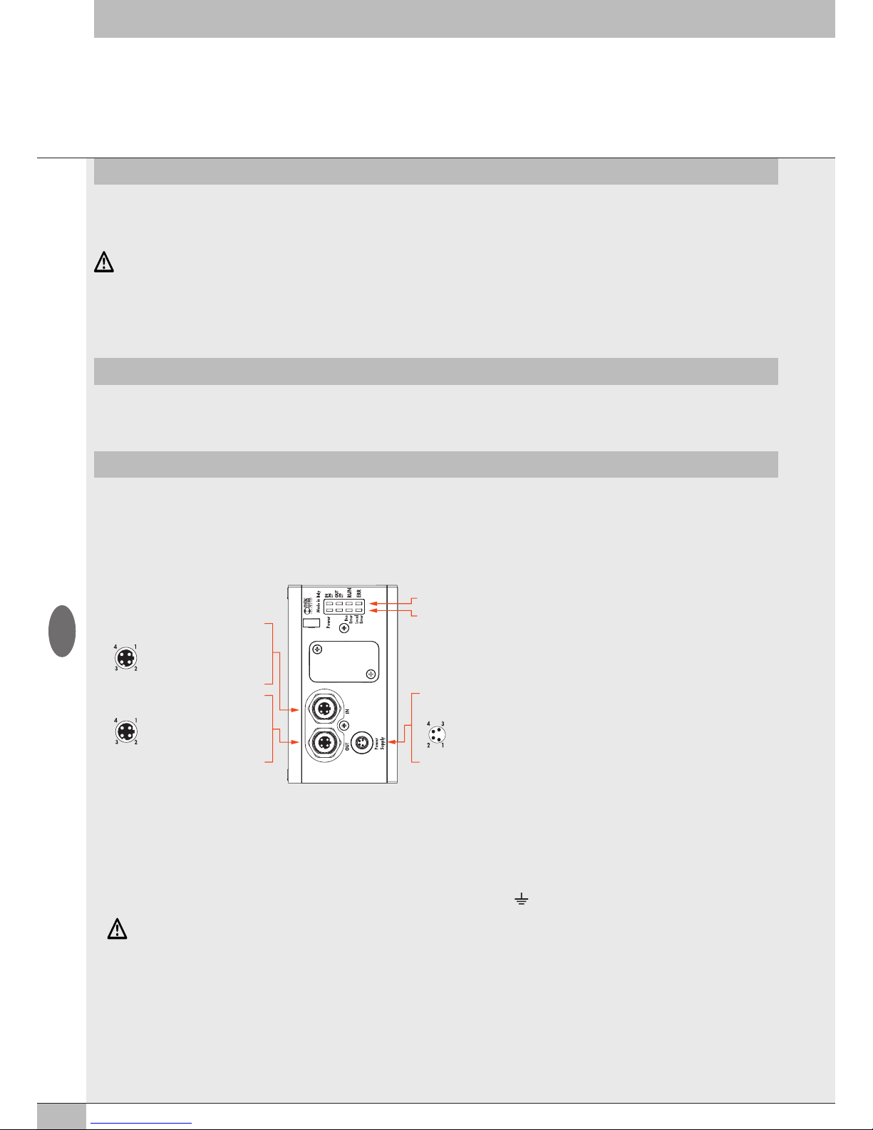
30
The EtherCAT Electrical Connection can be used to connect the EB 80 system to a EtherCAT network. In compliance with current specifications, the
EtherCAT offers diagnostic functions and is available in the configuration up to 128 outputs for solenoid pilots, 128 digital outputs, 128 digital inputs,
16 analogue outputs, 16 analogue inputs and 16 inputs for temperature measurement
INTENDED USE
This manual is intended exclusively for technicians qualified in control and automation technology, who have acquired experience in installing,
commissioning, programming and diagnosing programmable logic controllers (PLC) and Fieldbus systems.
TARGET GROUP
1. INSTALLATION
1.1 GENERAL INSTRUCTIONS FOR INSTALLATION
Before carrying out any installation or maintenance work, switch off the following:
• compressed air supply;
• the operating power supply to solenoid valve / output control electronics.
1.2 ELECTRICAL CONNECTION AND DISPLAY ELEMENTS
WARNING
Failure to make the earth connection may cause faults and irrevocable damages in the event of electrostatic discharge.
In order to guarantee IP65 protection class, any discharge must be conveyed and unused M12 connections must be provided with a protective cap.
1.3 ELECTRICAL CONNECTIONS: PIN ASSIGNMENT OF CONNECTOR
1.3.1 M8 connector for node and output power supply
1 = +24V Power supply EtherCAT node and input / output modules
2 = +24V Auxiliary valve power supply
3 = GND
4 = GND
The EB 80 must be earthed using the end plate connection marked with the symbol PE
GB
WARNING
The EB 80 EtherCAT must only be used as follows:
• as designated in industrial applications.;
• in systems fully assembled and in perfect working order;
• in compliance with the maximum values specified for electrical ratings, pressures and temperatures.
• Only use power supply complying with IEC 742/EN60742/VDE0551 with at least 4kV insulation resistance (PELV).
EtherCAT diagnostic signaling LED
EB 80 Net diagnostic signaling LED
Connection to the EtherCAT network
Power Supply (M8 male connector)
IN (M12 female connector, D encoding)
OUT (M12 female connector, D encoding)
1 = TD+
2 = RD+
3 = TD4 = RDMetal ring nut = Shield
1 = TD+
2 = RD+
3 = TD4 = RDMetal ring nut = Shield
1 = +24V bus (Brown)
2 = +24V valve (White)
3 = GND (Blue)
4 = GND (
Black
)
Connection for node power supply and
auxiliary valve power supply
Page 31
31
GB
1.3.2 M12 connector for connection to the EtherCAT network
1 = TD+
2 = RD+
3 = TD4 = RDMetal ring nut = Shield
The network connectors are the M12 D-coded type, in accordance with EtherCAT specifications. Pre-wired Industrial Ethernet cables can be used
to prevent any malfunction due to faulty wiring or, as an alternative, recyclable Industrial Ethernet 4-pin M12 metallic male connectors can also be
used. Connection to Master may require an RJ45-M12 male D-coded connecting cable to be provided with the following Metal Work catalogue
codes:
• 0240005050 - RJ45 4-pin connector to IEC 60 603-7;
• 0240005093 / 095 /100100100 - Straight M12 D-coded connector for bus with cable.
WARNING
For correct communication, only use Industrial Ethernet cables, cat. 5 / Class D 100MHz of the type shown in the Metal Work catalogue.
Incorrect installation can cause transmission errors and lead to malfunction of the devices.
The most frequent causes of data transmission faults are:
• wrong connection of shield or leads;
• cables too long or unsuitable;
• Network components unsuitable for branching.
1.4 POWER SUPPLY
An M8 4-pin female connector is used for the power supply. The auxiliary power supply of the valves is separate from that of the fieldbus, which
means that the valves can be powered off while the bus line remains live. The absence of auxiliary power is indicated by the flashing of the Led Power
light and simultaneous flashing of all the solenoid valve Led lights. The fault is relayed to the Master, which provides for adequate management of the
alert.
WARNING
Power off the system before plugging or unplugging the connector (risk of functional damage).
Use fully assembled valve units only.
Only use power packs complying with IEC 742/EN60742/VDE0551 with at least 4kV insulation resistance (PELV).
1.4.1 Supply voltage
The system provides a wide voltage range, from 12VDC -10% to 24VDC +30% (min 10.8, max 31.2).
WARNING
Voltage greater than 32VDC irrevocably damages the system.
SYSTEM VOLTAGE DROP
Voltage drop depends on the input maximum current drawn by the system and the length of the cable for connection to the system.
In a 24VDC-powered system, with cable lengths up to 20 m, voltage drops do not need to be taken into account.
In a 12VDC-powered system, there must be enough voltage to ensure correct operation. It is necessary to take into account any voltage drops due
to the number of active solenoid valves, the number of valves controlled simultaneously and the cable length.
The actual voltage supplied to the solenoid pilots must be at least 10.8 V.
A synthesis of the verification algorithm is shown here below.
Maximum current: I max [A] = (no. of solenoid pilots controlled simultaneously x 3.2) + (no. of active solenoid valves x 0.3)
VDC
Voltage drop: with a M8 cable: ΔV = I max [A] x Rs [0.067Ω/m] x 2L [m]
Where Rs is the cable resistance and L its length.
The voltage at the cable inlet, Vin must be at least 10.8 V + ΔV
Example:
12V supply voltage, 5 m cable, 3 pilots activate while other 10 are already active:
I max = (3 x 3.2) + (10 x 0.3) = 1.05 A
12
ΔV = (1.05 x 0.067) x (2 x 5) = 0.70 V
This means that at the power supply voltage greater than or equal to 10.8 + 0.7 = 11.5 V is required.
Vin =12 V > 11.5
→
OK
Page 32
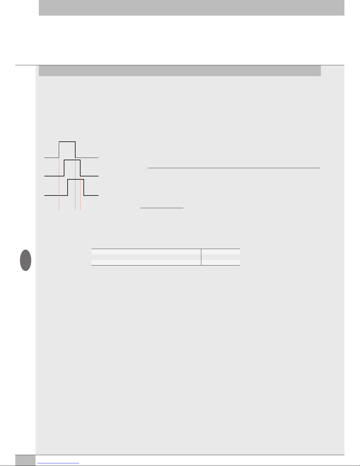
32
1.4.2 Input current
Solenoid valves are controlled via an electronic board equipped with a microprocessor.
In order to ensure safe operation of the valve and reduce energy consumption, a “speed-up” control is provided, i.e. 3W is supplied to solenoid
pilot for 15 milliseconds and then power is gradually reduced to 0.25W. The microprocessor regulates, via a PWM control, the current in the
coil, which remains constant regardless of the supply voltage and temperature, thus keeping the magnetic field generated by the solenoid pilot
unchanged.
For the system power supply to be properly scaled, it is important to take into account the number of valves to be controlled simultaneously* and
the number of those already active.
*By simultaneous control is meant the activation of all solenoid pilots with a time difference less than 15 milliseconds.
P1
P3
P2
T2T1
15 ms
T1 = P1 + P2 + P3 = 3 simultaneously-controlled solenoid pilots
T2 = P2 + P3 = 2 simultaneously-controlled solenoid pilots
Total power consumed during speed-up 3.2 W
Total power consumed during the holding phase 0.3 W
Power consumed by the fieldbus electrical terminal 4 W
Summary table
The input current of 180 mA consumed by the fieldbus electrical terminal must be added to the resulting current.
The maximum current required to control solenoid valves and supplied by the EtherCAT power supply connection terminal is 4A.
If the current exceeds the maximum value, an Intermediate module - M with additional power supply must be added to the system
(see subsection 3.1).
1.5 MAINS CONNECTION
For installation instructions, please refer to the ETG (EtherCAT Tecnology Group) guidelines.
http://www.ethercat.org
1.5.1 Use of Switches
The EB 80 EtherCAT electrical connection comes with two EtherCAT communication ports that can be used to create linear networks.
The network can be divided into several segments, using additional switches.
Make sure that the devices used comply with Industrial Ethernet specifications and support all EtherCAT functions.
I max [A] =
(No. of simultaneously-controlled solenoid pilots x 3.2) + (no. of active solenoid pilots x 0.3)
VDC
Example:
No. of simultaneously-controlled solenoid pilots = 10
No. of active solenoid pilots = 15
VDC = Supply voltage 24
I max =
(10 x 3.2) + (15 x 0.3)
= 1.5 A
24
Total current consumption is equal to the power consumed by the solenoid pilots plus the
current consumed by the electronics controlling the bases. To simplify the calculation, you can
consider 3.2W consumed by each solenoid pilot simultaneously and 0.3W by each active
solenoid pilot.
GB
Page 33
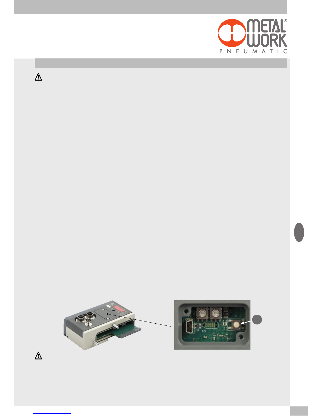
33
GB
2. COMMISSIONING
WARNING
Power off the system before plugging or unplugging the connector (risk of functional damage).
Connect the device to the earth using a suitable lead.
Failure to make the earth connection may cause faults and irrevocable damages in the event of electrostatic discharge.
Use fully assembled valve units only.
2.1 CONNECTIONS TO THE EB 80 EtherCAT SYSTEM
Connect the device to the earth.
Connect the IN input connector to the EtherCAT network.
Connect the OUT output connector to the next device. Otherwise close the connector with the cap provided to guarantee IP65 protection.
Connect the connector to the power mains. The power supply of fieldbus supply is separate from that of the valves.
The valves can be powered off keeping the communication with EtherCAT controller active.
2.2 INSTALLATION OF THE EB 80 SYSTEM IN A EtherCAT NETWORK
2.2.1 ESI configuration file
To configure the EB 80 system correctly in a EtherCAT network, upload the ESI Metalwork_EB80 file to the programming software used.
It can be downloaded quickly and easily from http://www.metalwork.it/ita/download.html
The ESI configuration file explains the characteristics of the EB 80 EtherCAT system.
In order for it to be identified as a EtherCAT device and its inputs and outputs be properly configured, the file must be imported into the controller
development environment.
As an alternative, the description of the device is written in its internal memory and be read online from the Master.
2.2.2 Address assignment
Two addressing modes are available.
Auto-Increment Address: the Master detects the physical position of the module inside the network and automatically assigns the address
(topological addressing). When the module is switched off the address is lost. When the module is switched on again, if the physical position has
not changed, the Master re-assigns the previous address. If the position has changed, the Master indicates an error.
Second Slave Address: the address can be assigned via a configuration tool, e.g. the TwinCAT
®
software using the Configured Station Alias
address.
With this function, the address is stored permanently in the EEPROM and is held even when the module is switched off.
2.3 EB 80 SYSTEM CONFIGURATION
Before using the EB 80 system, it is necessary to configure it through a procedure that reveals its composition.
Proceed as follows:
- disconnect the M8 power connector;
- open the door of the module;
- press button "A" and reconnect the M8 power connector, by holding it down until all the indicator lights on the system, valve bases, signal modules
and additional islands temporarily flash.
The EB 80 system is highly flexible and its configuration can be changed at any time by adding, removing or altering the bases for valves, signal
modules or additional islands.
The configuration must be effected after each change made to the system.
In the case of islands with additional electrical connection or M8 modules with 6 digital outputs + power supply, for them to be properly configured,
all the modules must be powered.
A
IMPORTANT
If the initial configuration has been changed, some solenoid valve addresses are likely to displace.
Address displacement occurs in any of the following cases:
• the addition of valve bases among existing ones;
• the replacement of a valve base with one of a different type;
• the elimination of one or more intermediate valve bases;
• the addition or elimination of islands with Additional Electrical Connection between pre-existing islands.
The addition or elimination of additional islands at one end of the system does not entail any address displacement.
The new addresses are subsequent to existing ones.
• The increase in the number of valve base bytes (pneumatic module) when digital output modules have already been configured.
Page 34
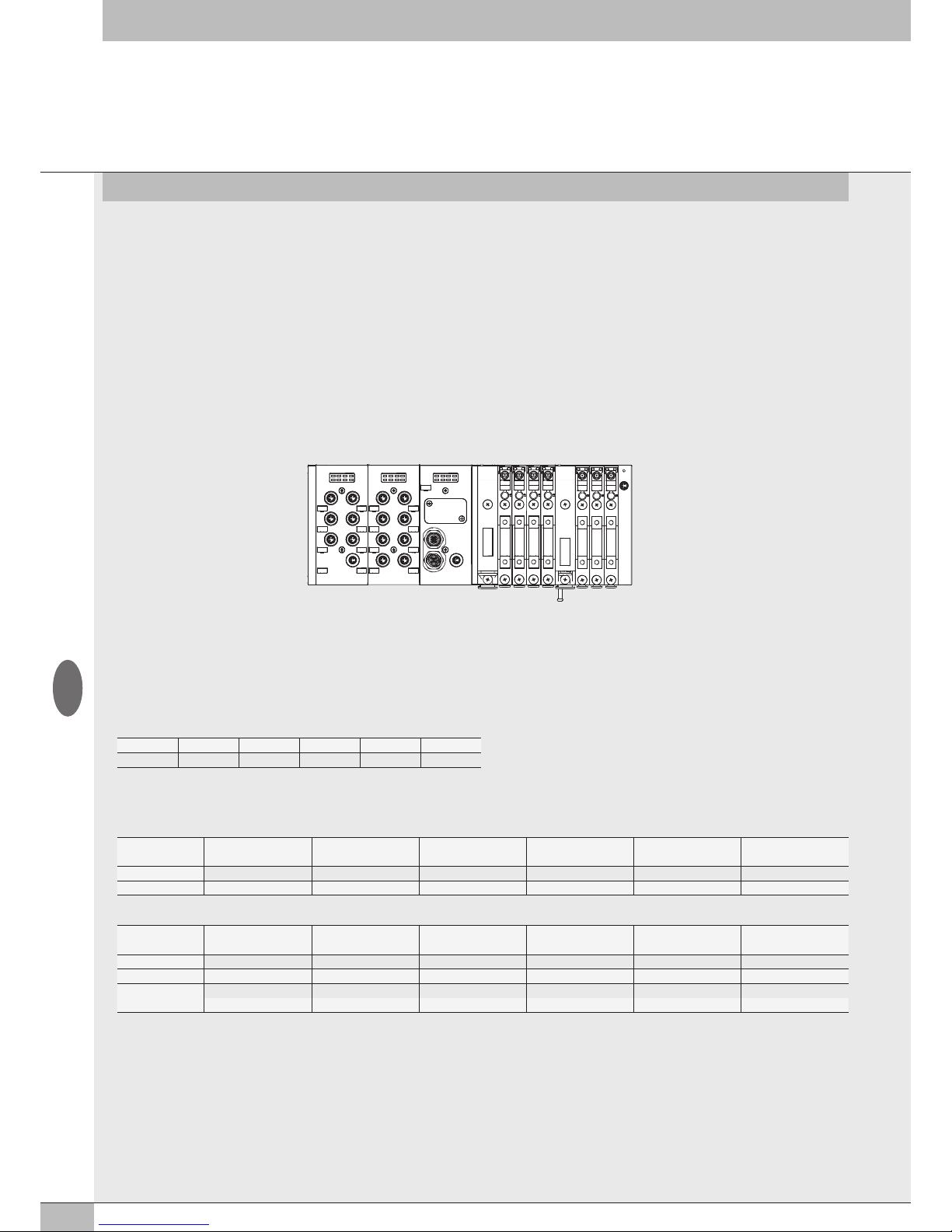
34
2.5 CONFIGURING THE EB 80 SYSTEM IN EtherCAT NETWORK
With the device powered on and connected to the network, perform a scan of the network. The device will be automatically detected by the Master.
As an alternative, an offline configuration can be performed by selecting the EB 80 EtherCAT from the development system hardware catalogue, then
insert it into the configuration. All the output and the input bytes, including the byte indicating the EB 80 system diagnostic state, are assigned to the
device.
2.5.1 Assigning data bits to solenoid valve base outputs
bit 0 bit 1 bit 2 bit 3 ... bit 128
Out 1 Out 2 Out 3 Out 4 ... Out 128
2.5.2 Examples of solenoid pilot output addresses
Base for 3- or 4-control valves – Only valves with one solenoid pilot can be installed.
Valve type
Valve with
1 solenoid pilot
Valve with
1 solenoid pilot
Dummy or
bypass valve
Valve with
1 solenoid pilot
Dummy or
bypass valve
Valve with
1 solenoid pilot
1 solenoid pilot
14 14 - 14 - 14
Output
Out 1 Out 2 Out 3 Out 4 Out 5 Out 6
Base for 6- or 8-control valves - One or two solenoid pilots can be installed.
Valve type
Valve with
2 solenoid pilots
Valve with
1 solenoid pilot
Dummy or
bypass valve
Valve with
1 solenoid pilot
Dummy or
bypass valve
Valve with
2 solenoid pilots
1 solenoid pilot
14 14 - 14 - 14
2 solenoid pilot
12 - - - - 12
Output
Out 1 Out 3 Out 5 Out 7 Out 9 Out 11
Out 2 Out 4 Out 6 Out 8 Out 10 Out 12
Each base occupies all the positions.
The control of non-connected outputs generates an interrupted solenoid pilot alarm.
2.4 ADDRESSING
The following address volume is made available to the Master:
• 16 bytes for valve bases (pneumatic module), maximum 128 solenoid pilots (0-15 Output bytes);
• 16 bytes for 8 digital output signal modules, maximum 128 total digital outputs (16-31 Output bytes);
• 22 bytes for 6 digital outputs + power supply, maximum 128 total digital outputs (32-53 Output bytes);
• 32 bytes for analogue output signal modules, maximum 16 analogue outputs (54-85 Output bytes);
• 16 bytes for 16 digital output signal modules, maximum 128 total digital outputs (86-101 Output bytes);
• 1 diagnostic byte (0 Input).
• 16 bytes for 8 digital input signal modules, maximum 128 total digital inputs (1-16 Input bytes);
• 32 bytes for analogue input signal modules, maximum 16 analogue inputs (17-48 Input bytes);
• 48 diagnostic byte EB 80 I4.0 (49-96 Input bytes);
• 16 bytes for 16 digital input signal modules, maximum 128 total digital inputs (97-112 Input bytes);
• 32 bytes for analogue input signal modules for temperature measurement, maximum 16 analogue inputs (113-144 Input bytes);
All modules are addressed sequentially.
The addressing of signal modules is sequential by type.
DO 1-6 DI 1-8 E1 E7
GB
Page 35
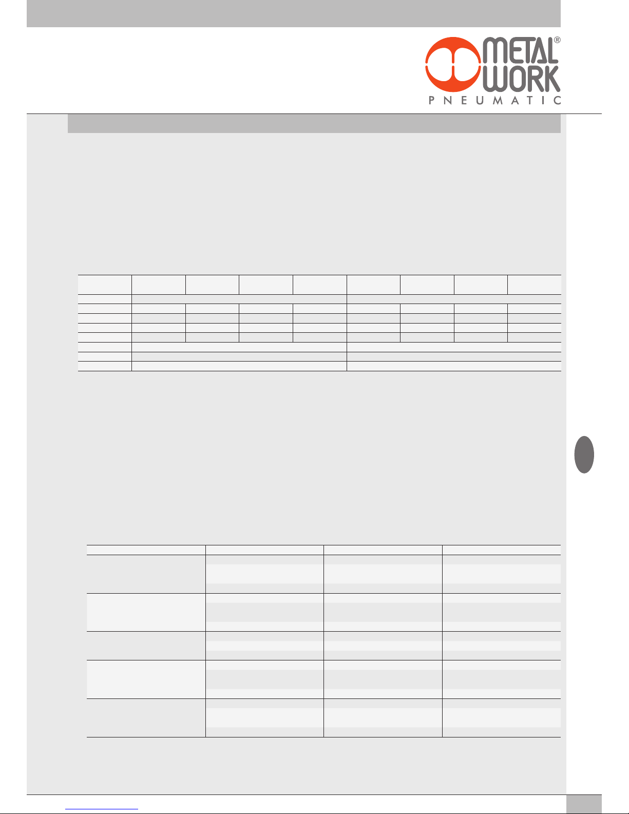
35
When the communication is restored, the state of the solenoid valves is resumed by the Master. To prevent uncontrolled movements, the Master
must ensure proper management of the event.
2.5.3.1 Start-up parameters - 0x8001:03– System start
• 0x8001:03 = 0
External/default parameters: during each start-up phase the system must be initialised by the Master, which sends all configuration
parameters such as input/output type, etc
• 0x8001:03 = 1
Saved parameters: at the first start-up phase, the parameters sent by the Master are saved and used for subsequent startup phases.
This enables a quicker system startup phase.
2.5.3.2 Analogue input display 0x8001:04 – Visualization of analog values
• 0x8001:04 = 1 I
NTEL or little-endian logic: storage that starts from the least significant byte and finishes with the most significant byte.
• 0x8001:04 = 0
Motorola or big-endian logic: storage that starts from the most significant byte and finishes with the least significant byte (default).
2.5.3.3 Analogue data format 0x8001:05 – Analog input data format
Enables the analogue data format to be set in two modes:
• 0x8001:05 = 0
Sign + 15 bit - the analogue value is between +32767 and -32768 which is obtained with the maximum analogue value permitted
by the type of input. The values are outlined in the table.
• 0x8001:05 =1
Linear scaled – the analogue value measured refers to the value set in the user "full scale range" in "General Properties" –
"Analogue Module Unit Parameters". Can be set individually for each analogue channel. (See 3.3.4.4 User full scale).
No. of outputs Out 4 Out 3 Out2 Out1 Out 8 Out 7
Out 6 Out 5
Byte 1 2
bit 7 - 6 5 - 4 3 - 2 1 - 0 7 - 6 5 - 4
3 - 2 1 - 0
Fault mode Set Set Set Set Reset Reset Reset Reset
Value 2 2 2 2 1 1 1 1
bit 10 10 10 10 01 01 01 01
Byte 10101010 01010101
Hex 0xAA 0x55
Settings 0x8010:1 = 0xAA 0x8010:2 = 0x55
Analogue value Digital value Signal
Input type -10… + 10 V
+11.7 V 32767 Overflow
+ 10 V
-10 V
28095
- 28095
Nominale range
-11.7 -32768 Underflow
Input type -5… + 5 V
+5.8 32767 Overflow
+ 5 V
- 5 V
28095
- 28095
Nominale range
-5.8 -32768 Underflow
Input type 1… + 5 V
+5.8 32767 Overflow
+ 5 V 28095 Nominale range
0 V 0 Underflow
Input type -20 mA … + 20 mA
+23 mA 32767 Overflow
+20mA
- 20mA
28095
- 28095
Nominale range
-23 mA -32768 Underflow
Input type 4 mA … + 20 mA
+23 mA 32767 Overflow
20mA
4 mA
27307
5513
Nominale range
0 mA 0 Underflow
2.5.3 Unit parameter configuration - 0x8001:02 – Fail safe output
This function can be used to determine the state of digital and analogue output solenoid pilots When the communication with the Master is
interrupted. Three different modes can be selected for the pneumatic module via 0x8001:02 – Params_Head_ NetX –SubIndex 002
• Output Reset (default), all the solenoid pilots are disabled. 0x8001:02 = 00
• Hold Last State, all the solenoid pilots remain at the state they found themselves When the communication with the Master was interrupted.
0x8001:02 = 01
• Output Fault mode, 0x8001:02 = 02. The behaviour of each pilot can be selected from among three modes, by setting 0x8010:0 - Fail Safe.
The parameter is an array of 32 bytes and allows the configuration of each pneumatic module pilot, leaving 2 bits for each channel.
- Value = 0 Hold Last State, the solenoid pilot remains at the state it found itself before the communication with the Master was interrupted.
- Value = 1 Reset Output (default), the solenoid pilot remains disabled.
- Value = 2 Set Output, the solenoid pilot activates when the communication with the Master is interrupted.
Example: a pneumatic module with 8 solenoid pilots, in case of failed communication with the Master, the first 4 are enabled, the other 4 are
disabled.
GB
Page 36
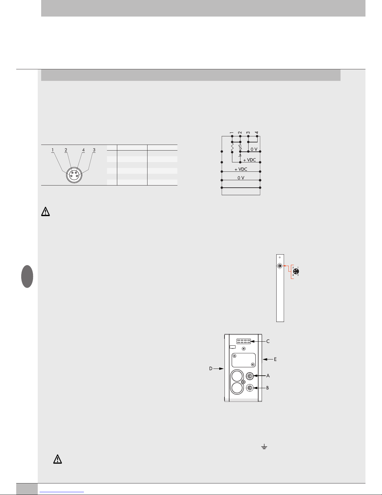
36
3. ACCESSORIES
3.1 INTERMEDIATE MODULE - M, WITH ADDITIONAL POWER SUPPLY
Intermediate modules with additional power supply can be installed between valve bases. They either provide additional power supply when
numerous solenoid pilots are activated at the same time or electrically separate some areas of the valve island from others, e.g. when some solenoid
valves need to be powered off when a machine safety guard needs to be opened or an emergency button has been pressed, in which case only the
valves downstream the module are powered on. Various types are available with different pneumatic functions.
The maximum solenoid valve control current supplied by the intermediate module with additional power supply is 8A.
WARNING
It cannot be used as a safety function as it only prevents power supply from turning on.
Manual operation or faults can cause involuntary movements. For greater security, relieve all pressure in the compressed air system before carrying
out hazardous operations.
PIN Colour Function
1 Brown +VDC
2 White +VDC
3 Blue GND
4 Black GND
WARNING
Failure to make the earth connection may cause faults and irrevocable damages in the event of electrostatic discharge. In order to guarantee
IP65 protection class, any discharge must be conveyed and the unused M12 connector must be provided with a protective cap.
3.2.1.1 Electrical connections: pin assignment of M8 connector for Additional Electrical Connection power supply
1 = 24VDC Additional electrical connection power supply and Input/Output modules
2 = 24VDC Valve auxiliary power supply
3 = GND
4 = GND
The device must be earthed using the connection of the closing end plate marked with the symbol PE
3.2.1 Electrical connections and signal display elements
A Connection to the EB 80 Net network
B Connection to power the Additional electrical line and the valve
auxiliary line
C EB 80 diagnostic indicator light
D Connection to Signal modules
E Valve base connection
1 = +24V bus
2 = +24V valve
3 = GND
4 = GND
3.2 ADDITIONAL ELECTRICAL CONNECTION - E0AD
Additional Electrical Connection – E can be used to connect multiple EB 80 systems to one EtherCAT node.
To do this, the main island must be equipped with a C3-type blind end plate with an M8 connector.
The connection of multiple systems requires all the additional islands to be equipped with C3 blind end plates,
except for the last one that must be fitted with a C2 blind end plate with an EB 80 Net serial line termination
connector.
Optionally, if a provision for subsequent upscale is required, a C3 blind end plate can be installed also on the
last-in-line island, in which case it is necessary to add an M8 termination connector code 02282R5000.
For proper operation of the entire EB 80 Net system, only use the prewired, shielded and twisted M8-M8
cables shown in Metal Work catalogue.
Additional electrical connection can be used to connect bases for valves and signal modules - S, just like with
islands with a EtherCAT node.
End plate with intermediate control
EB 80 Net (M8 Female Connector)
1 = CAN H
2 = CAN L
3 = Token
4 = GND
+VDC Valve
+VDC Bus
Bus Line
+VDC Valve
+VDC Bus
Bus Line
+VDC Valve
GB
Page 37
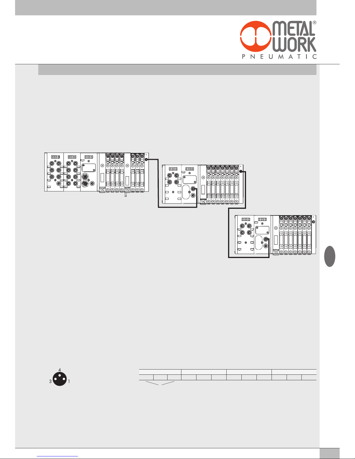
37
3.2.2 Addressing the Additional Electrical Connection - E0AD
All the modules are addressed in sequence.
• Addressing valve solenoid pilots - from the first solenoid pilot of the EtherCAT node to the last solenoid pilot of the last-in-line additional island.
• Addressing digital input S modules - from the first module connected to the EtherCAT node to the last digital input S module of the last-in-line
additional island.
• Addressing digital output S modules - from the first module linked to the EtherCAT node to the last digital output S module of the last-in-line
additional island.
• Addressing analogue input S modules - from the first module linked to the EtherCAT node to the last analogue input S module of the last linked
additional island.
• Addressing analogue output S-modules - from the first module linked to the EtherCAT node to the last analogue output S module of the
last-in-line additional island.
3.3.1.3 Polarity - 0x8020 - Polarity DI8 - 0x8070 Polarity DI16
The polarity of each input can be selected as follows. The polarity is determined by 8020:0 Params_DI_Polarity.
There are 16 SubIndex tasks corresponding to 16 S modules that can be installed in the system.
• 0x8020:xx = 0 PNP, the signal is active when the signal pin is connected to +VDC
• 0x8020:xx = 1 NPN, the signal is active when the signal pin is connected to 0VDC.
The signal LED light is ON when the input is active.
Example of configuration of the first connected S module, with 8 NPN inputs: 8020:01 SubIndex 001 = 255 (0xFF)
Example of configuration of the third connected S module, with the first 4 NPN inputs and the following 4 PNP inputs:
8020:03 SubIndex 003 = 15 (0x0F).
DO 1-6 DI 1-8 E1 E7
AI 1-4 E8 E15
AI 5-8 E16 E23
3.3 SIGNAL MODULES - S
EB 80 systems are supplied with numerous modules for controlling input or output signals.
These modules can be added to systems with either a EtherCAT electrical connection or ones with Additional Electrical Connection.
3.3.1 Digital Input module
Digital 8-Input M8 module: each module can handle up to 8 digital inputs. It is defined with 1 byte, starting from byte IN 1.
16 digital input terminal board module: each module can handle up to 16 digital inputs. It is defined with 2 byte, starting from byte IN 98.
Each input has some parameters that can be configured individually via the CoE (CAN over EtherCAT) protocol.
The digital input module makes it possible to read digital inputs with a maximum signal exchange frequency of 1kHz.
High-frequency reading is possible for all inputs, with up to a maximum of 2 modules connected to the EB 80 network.
3.3.1.1 Type of inputs and power supply
Two- or three-wire digital PNP or NPN sensors can be connected. The sensors can be supplied by either a EtherCAT node or Additional
Electrical Connection power supply. In this way the sensors remain active even when the valve auxiliary power supply is switched off.
3.3.1.2 Electrical connections
Pin assignment of M8 connector Pin assignment of terminal board connectors
1 = +VDC (Sensor power supply)
3 = GND (Sensor power supply)
4 = Input
Input X1 - X5 - X9 - X13 Input X2 - X6 - X10 - X14 Input X3 - X7 - X11 - X15 Input X4 - X8 - X12 - X16
+ Input 0 + Input 0 + Input 0 + Input 0
Sensor power supply
GB
Page 38
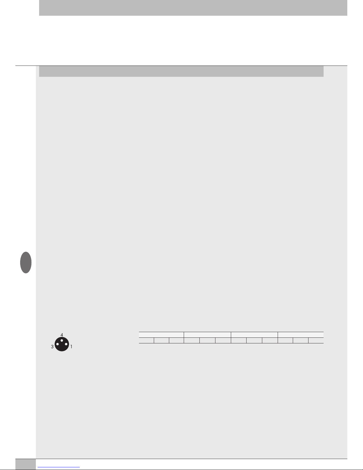
38
3.3.1.4 Operating state 0x8021 - Activation state DI8 - 0x8071 Activation state DI16
The operating state can be selected individually for each input. It is defined by 8021:0 Params_DI_ActStatus. There are 16 SubIndex tasks
corresponding to 16 S modules that can be installed in the system.
• 0x8021:xx = 0 Normally Open, the signal is ON when the sensor is enabled. The LED light is on when the sensor is enabled.
• 0x8021:xx = 1 Normally Closed, the signal is ON when the sensor is disabled. The LED light is on when the sensor is disabled.
Example of configuration of the first connected S module, with 8 NC inputs: 8021:01 SubIndex 001 = 255 (0xFF)
Example of configuration of the third connected S module, with the first 4 NC inputs and the following 4 NO inputs:
8020:03 SubIndex 003 = 15 (0x0F).
3.3.1.5 Signal persistence 0x8022 - Signal extension DI8 - 0x8072 Signal extension DI16
This function is designed to keep the input signal active for a minimum time corresponding to the set value, thus allowing the PLC to detect
signals with low persistence times.The persistence of the signal is defined by 8022:0 Params_DI_SignExt. There are 16 SubIndex tasks
corresponding to 16 S modules that can be installed in the system. Each module is def ined by 2 Bytes, up to a total of 32 bytes.
• 0x8022:xx =0 - 0 ms: filter off.
• 0x8022:xx =1 - 15 ms: signals with activation/deactivation times less than 15 ms are kept active for 15 ms.
• 0x8022:xx =2 - 50 ms: signals with activation/deactivation times less than 50 ms are kept active for 50 ms.
• 0x8022:xx =3 - 100 ms: signals with activation/deactivation times less than 100 ms are kept active for 100 ms.
3.3.1.6 Input filter 0x8023 - Debounce time DI8 - 0x8073 Debounce time DI16
This is a time filter that can be set individually for each input to filter and NOT detect signals lasting less than the set time. This function
can be used to avoid the detection of false signals. The input filter is defined by 8023:0 Params_DI_DebTime. There are 16 SubIndex tasks
corresponding to 16 S modules in the system. Each module is defined by 2 Bytes, up to a total of 32 bytes.
• 0x8023:xx = 0 - 0 ms: filter off.
• 0x8023:xx = 1 - 3 ms: signal state changes less than 3 ms are not detected.
• 0x8023:xx = 2 - 10 ms: signal state changes less than 10 ms are not detected.
• 0x8023:xx = 3 - 20 ms: signal state changes less than 20 ms are not detected.
3.3.2.3 Polarity 0x8030 - Polarity DO8 - 0x8080 Polarity DO16
The polarity of each output can be selected as follows. The polarity is determined by 8030:0 Params_DI_Polarity. There are 16 SubIndex tasks
corresponding to 16 S modules that can be installed in the system.
• 0x8030:xx = 0 - PNP, when the output is active the signal pin shows +VDC. To power a load it is necessary to connect the other end to
0VDC.
• 0x8030:xx = 1 - NPN, when the output is active the signal pin shows +0VDC. To power a load it is necessary to connect the other end
to+VDC.
Example of configuration of the first connected S module, with 8 NPN outputs : 8030:01 SubIndex 001 = 255 (0xFF)
Example of configuration of the third connected S module, with the 4 NPN outputs and the following 4 PNP outputs:
8030:03 SubIndex 003 = 15 (0x0F)
3.3.2.1 Type of output and power supply
Can be used to control different digital devices. The following devices are compatible:
• Solenoids
• Contactors
• Indicators
The outputs are powered by the EtherCAT node power supply, if any, the digital 6-ouput M8 Module and the previous power supply
(see 3.3.3.). Check that the inrush current and continuous currents of the connected devices do not exceed the currents supplied to each
connector and the maximum current of the module.
If the module is powered directly by the EtherCAT electrical connection, the power supply is common to the EtherCAT node.
A suitable external protection must be provided to prevent the device from being damaged permanently.
3.3.2.2 Electrical connections
Pin assignment of M8 connector Pin assignment of terminal board connectors
3.3.2 Digital Output module
Each Digital 8-Output M8 module can handle up to 8 digital otputs. It is defined with 1 byte, starting from byte Out 16.
16 digital Output terminal board module: each module can handle up to 16 digital otputs. It is defined with 2 byte, starting from byte Out 87.
Each byte has a few individually configurable parameters via the CoE – CAN over EtherCAT function.
Output X1 - X5 - X9 - X13 Output X2 - X6 - X10 - X14 Output X3 - X7 - X11 - X15 Output X4 - X8 - X12 - X16
+ Output 0 + Output 0 + Output 0 + Output 0
1 = +VDC (COM for OUT NPN)
3 = GND (COM for OUT PNP)
4 = Output
GB
Page 39
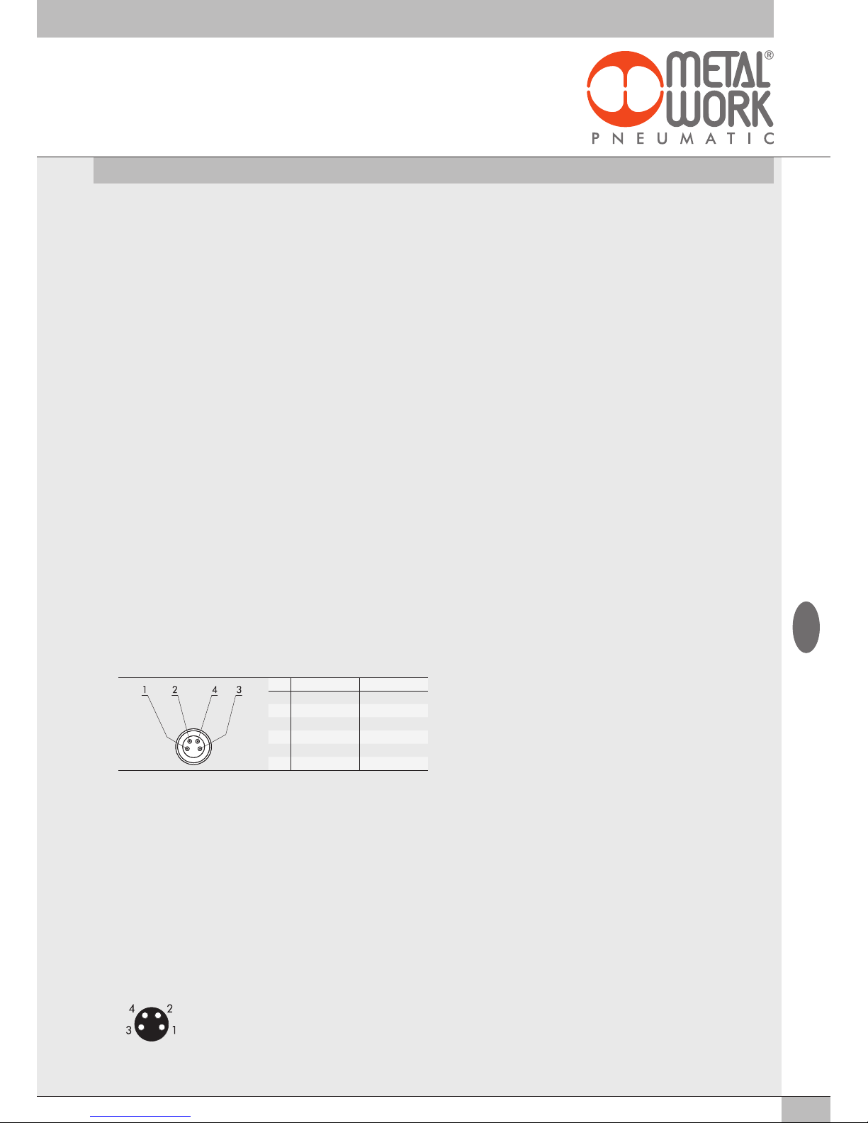
39
3.3.2.4 Operating state 0x8031 - Activation State DO8 - 0x8081 Activation State DO16
The operating state of each output can be selected as follows. The operating state is defined by 8031:0 Params_DO8_ActStatus.
There are 16 SubIndex tasks corresponding to16 S modules that can be installed in the system.
• 0x8031:xx = 0 - Normally Open, the output is active when it is controlled by the control system. The Led light is on when the output is
controlled.
• 0x8031:xx = 1 - Normally Closed, the output is active when it is NOT controlled by the control system. The Led light is active then the output
is NOT controlled.
Example of configuration of the first connected S module, with 8 NC outputs: 8031:01 SubIndex 001 = 255 (0xFF)
Example of configuration of the third connected S module, with the first 4 NC outputs and the following 4 NO outputs:
8031:03 SubIndex 003 = 15 (0x0F)
3.3.2.5 Fail safe outputs - Fail safe DO8 - 0x8082 Fail safe DO16
This function can be used to determine the output state when communication with the Master is interrupted. The safety state is defined by
0x8032:0 Params_DO8_FailSafe. There are 16 SubIndex tasks corresponding to 16 S modules that can be installed in the system.
• Output Reset (default), all outputs are disabled. It is set by 0x8001:02 – Params_Head_ NetX
• Output Fault mode, 0x8032:xx. The behaviour of each solenoid pilot can be selected from among three modes by setting 0x8032:
- Fail Safe.
The parameter is an array of 32 bytes and allows the configuration of each pneumatic module pilot, leaving 2 bits for each channel.
- Value = 0 Hold Last State, the solenoid pilot remains at the state it found itself before communication with the Master was interrupted.
- Value = 1 Reset Output (default), the solenoid pilot is disabled.
- Value = 2 Set Output, the solenoid pilot activates When the communication with the Master is interrupted.
Example: see subsection 2.5.3
When the communication is restored, the state of the solenoid valves is resumed by the Master.
To prevent uncontrolled movements, the Master must ensure proper management of the event.
3.3.2.6 Faults and alarms
Each module output is protected against overload and short-circuit. The alarm signal is reset automatically.
The output is controlled briefly every 30 seconds to check whether the failure has been removed and to perform automatic reset.
The Master must manage the event properly to prevent any uncontrolled movements.
3.3.4 Analogue 4-Input M8 Module
Each module can handle up to 4 analogue inputs with freely configurable voltage and current.
Each input is defined by 2 bytes, starting from byte In 17.
This module converts signals with a resolution of 15 bits plus the sign. The numerical values available to the control system are between –32768
and +32767.
Some of the paramaters can be configured individually.
The Module can recognise out-of-range values, and disconnection of the sensor itself in the case of 4-20 mA or 1-5 V sensors, due to a broken
cable for example. The alerts displayed and corresponding error codes are outlined in sections 4.1 and 4.3.3.
3.3.4.1 Electrical connections: Pin assignment of M8 connector
Rhe supply voltage +V corresponds to either the EtherCAT node supply voltage or the Additional Electrical Connection.
1 = +V
2 = + Analog IN
3 = GND
4 = - Analog IN
Connector - ring = Shield
3.3.3.1 Auxiliary power supply
The current is the sum of the currents supplied by the Digital 6-Output M8 Module plus that supplied by all the downstream signal modules
connected upstream of another Digital 6-Output M8 Module + power supply.
The maximum current supplied by the modules connected downstream the Digital 6-Output M8 Module + power supply is 8A.
PIN Colour Function
1 Brown +VDC
2 White +VDC
3 Blue GND
4 Black GND
3.3.3 Digital 6-Output M8 Module + electrical power supply
Each module can handle up to 6 digital outputs and can be configured exactly like the M8 8-digital output module via the 8040:0, 8041:0,
8042:0 objects. It is defined with 1 byte, starting from byte Out 32.
It comes with a connector for auxiliary power supply, which makes it possible to increase the current supplied by the module and system.
The auxiliary supply of this module powers all downstream modules, including input modules.
GB
Page 40
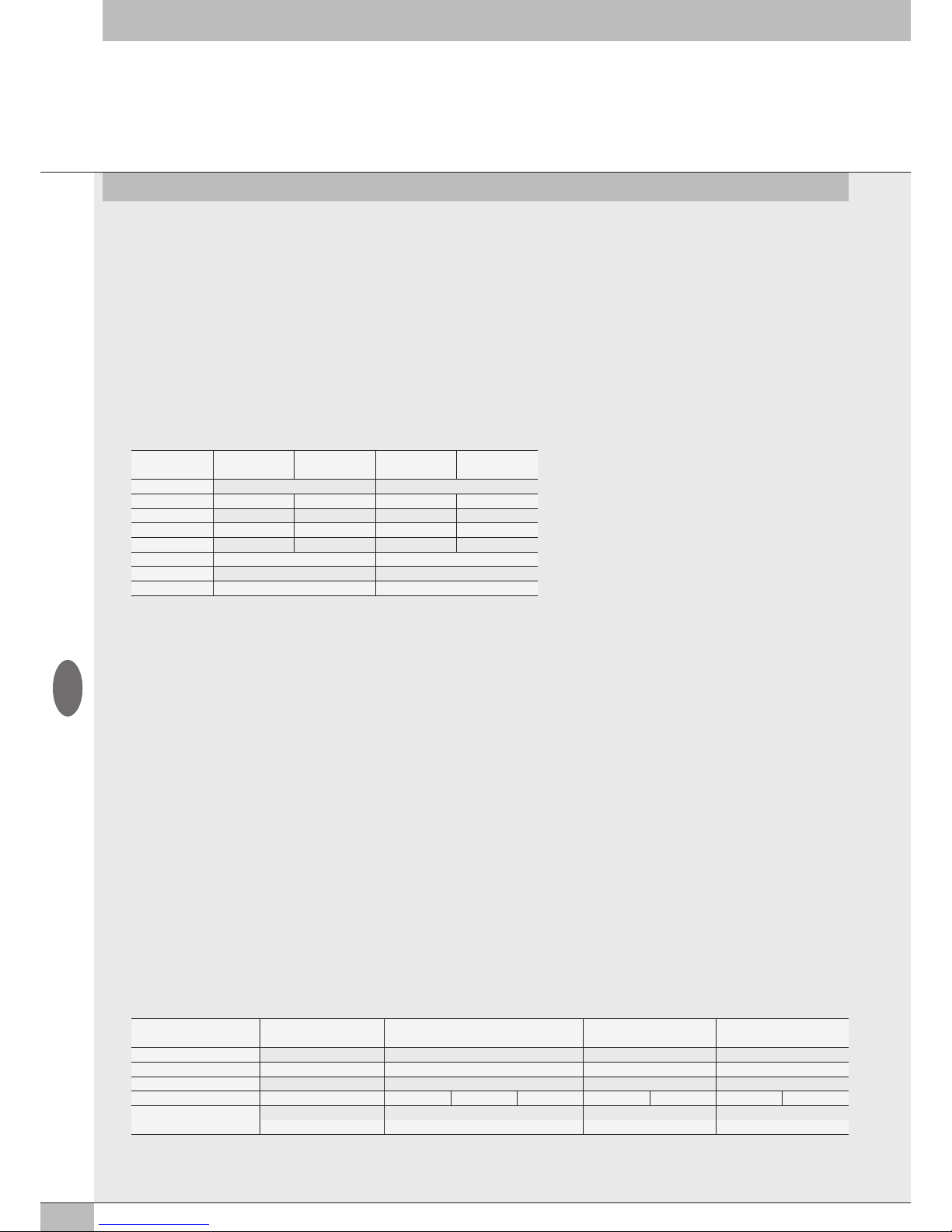
40
3.3.4.2 Signal range 0x8050 - Signal range AI
Each channel can be configured with a type of input signal.
The 0x8050 is an array of 8 bytes. Each input is defined by 4 bits, up to a total of 2 bytes per module.
The following types are available:
• 0x8050:xx = 0 OFF
• 0x8050:xx = 1 0..10 Vdc
• 0x8050:xx = 2 - 10/+10 Vdc
• 0x8050:xx = 3 0…5 Vdc
• 0x8050:xx = 4 -5 / +5 Vdc
• 0x8050:xx = 5 1…5 Vdc
• 0x8050:xx = 6 0…20 mA
• 0x8050:xx = 7 4…20 mA
• 0x8050:xx = 8 -20 / + 20 mA
If the channel is not used, it must be disabled by selecting OFF in order to avoid any interference
Example: first module, inputs X1 and X2 are configured 0..10 VDC, inputs X3 and X4 are configured 4…20 mA
No. of inputs X4 X3 X2 X1
Byte 2 1
bit 7 - 4 3 - 0 7 - 4 3 - 0
Range segnale 4…20 mA 4…20 mA 0..10 Vdc 0..10 Vdc
Value 7 7 1 1
bit 0111 0111 0001 0001
Byte 01110111 00010001
Hex 77 11
Settings 0x8050:02 = 77 0x8050:01 = 11
No. of inputs X4 X3 X2 X1
Byte 7 - 8 5 - 6 3 - 4 1 - 2
Full scale 26500 26500 10000 10000
Hex value 6784 6784 2710 2710
Bye settings 67 84 67 84 27 10 27 10
Settings
0x8052:07 = 67 0x8052:05 = 67 0x8052:03 = 27 0x8052:01 = 27
0x8052:08 = 84 0x8052:06 = 84 0x8052:04 = 10 0x8052:02 = 10
Note: the example is based on Motorola logic (parameter 0x8001:4 =0 Big Endian)
3.3.4.3 Filtering the value measuredo 0x8051 - Filter measured value AI
This function filters the value measured to make reading more stable. A mobile average is calculated on the number of samples chosen. Reading
slows down as the number of values increases.The 0x8050 is an array of 8 bytes. Each input is defined by 4 bits, up to a total of 2 bytes per
module.
The following values are available:
• 0x8051:xx = 0 No filter
• 0x8051:xx = 1 2 values
• 0x8051:xx = 2 4 values
• 0x8051:xx = 3 8 values
• 0x8051:xx = 4 16 values
• 0x8051:xx = 5 32 values
• 0x8051:xx = 6 64 values
Example: see signal range table chapter 3.3.4.2
3.3.4.4 User full scale 0x8052 - User full scale AI
This value can be set to change the scale of numerical values sent to the control system as a function of the analogue signal value. It must be
enabled by setting 0x8001:05 =1 Linear scaled.
Makes it possible to set values up to 27531 for voltage channels and 27566 for current channels. The value set is valid for positive and negative
signals, therefore if the signal range is set to 0-10 V for example, the maximum value will be 27531.
If the signal range is set to +/-10V the limit values will be +27531 and -27531. Setting higher values displays the following: Bus Error - Error in
Configuration Parameters.
This function makes it possible to obtain a read-out in engineering format, therefore if a 0-10 bar pressure transducer is connected to the
analogue channel and the user full scale is set to 10000, the value of the signal is expressed in mbar.byte. The 0x8050 is an array of 8 bytes.
Each input is defined by 16 bits, up to a total of 8 bytes per module.
Example: first module, inputs X1 and X2 can be configured with full scale = 10000, the inputs X3 and X4 can be configured with full scale = 26500
The following modules continue with subIndex numbering up to 0x8052:20
Note: the example is based on Motorola logic (parameter 0x8001:4 =0 Big Endian)
GB
Page 41
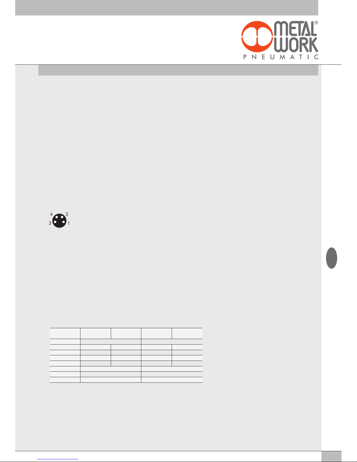
41
No. of inputs X4 X3 X2 X1
Byte 2 1
bit 7 - 4 3 - 0 7 - 4 3 - 0
Signal range 4…20 mA 4…20 mA 0..10 Vdc 0..10 Vdc
Value 7 7 1 1
bit 0111 0111 0001 0001
Byte 01110111 00010001
Hex 77 11
Settings 0x8060:02 = 77 0x8060:01 = 11
The following modules continue with subIndex numbering up to 0x8060:08
Note: the example is based on Motorola logic (parameter 0x8001:4 =0 Big Endian)
3.3.5 Analogue 4-Output M8 Module
Each module can handle up to 4 analogue outputs with freely configurable voltage and current.
This module converts signals with a resolution of 15 bits plus the sign. The numerical values settable in the control system are between –32768 and
+32767.
Some parameters can be configured individually, by selecting the module in the page entitled "Overview of Devices
→
Properties →
Parameters of the Unit".
3.3.5.1 Electrical connections: Pin assignment of M8 connector
The supply voltage +VDC corresponds to either the power supply voltage of the EtherCAT node or the Additional Electrical Connection.
1 = +VDC
2 = + Analog OUT
3 = GND
4 = Shield
3.3.5.2 Range Segnale 0x8060 - Signal range AO
Each channel can be configured with a type of output signal. The 0x8060 is an array of 8 bytes. Each output is defined with 4 bits, up to a total
of 2 bytes per module.
The following types are available:
• 0x8060:xx = 0 OFF
• 0x8060:xx = 1 0..10 Vdc
• 0x8060:xx = 2 - 10/+10 Vdc
• 0x8060:xx = 3 0…5 Vdc
• 0x8060:xx = 4 -5 / +5 Vdc
• 0x8060:xx = 6 0…20 mA
• 0x8060:xx = 7 4…20 mA
If the channel is not used, it can be disabled by selecting OFF to avoid any disturbances.
Example: first module, inputs X1 and X2 are configured 0..10 VDC, inputs X3 and X4 are configured 4…20 mA
3.3.4.5 Connection of sensors
3-wire voltage sensors
Pin 1 = +VDC sensor power supply
Pin 2 = + Analogue input
Pin 3 = GND
Pin 4 = NC
4-wire voltage sensors (differential)
Pin 1 = +VDC sensor power supply
Pin 2 = + Analogue input
Pin 3 = GND
Pin 4 = - Analogue input
2-wire current sensors
Pin 1 = +VDC sensor power supply
Pin 2 = + Analogue input
Pin 3 = NC
Pin 4 = NC
3-wire current sensors
Pin 1 = +VDC sensor power supply
Pin 2 = + Analogue input
Pin 3 = GND
Pin 4 = NC
GB
Page 42
42
3.3.5.3 User full scale 0x8061 - User full scale AO
These two values can be set to change the scale of numerical values sent to the control system to obtain a value of the output analogue signal.
The 15-bit signal conversion system plus the sign can be used to set values from – 32768 to +32767.
In case of need these values can be reduced. The 0x8061 is an array of 8 bytes. Each input is defined by 16 bits, up to a total of 8 bytes per
module.
Example: first module, outputs X1 and X2 are configured with full scale = 10000, outputs X3 and X4 are configured with full scale = 26500
The following modules continue with subIndex numbering up to 0x8052:20
Note: the example is based on Motorola logic (parameter 0x8001:4 =0 Big Endian)
3.3.5.4 Minimum monitor 0x8062 - Monitor lowest AO
The parameter is an array of 4 bytes. It is used to verify whether the value received by the Master is consistent with the value set under Minimum
Value 0x8064
3.3.5.5 Maximum monitor 0x8063 - Monitor Highest AO
The parameter is an array of 4 bytes. It is used to verify whether the value received by the Master is consistent with the value set under
Maximum Value 0x8065
3.3.5.6 Minimum value 0x8064 Lowest valve AO / Maximum value 0x8065 Highest valve AO
Values used for the monitor function.
Minimum value 0x8064
The parameter is an array of 32 bytes. Each output is defined by 2 bytes, up to a total of 8 bytes per module. It allows the setting of values up
to – 32768
Example: same as in table 3.3.5.3 Users Full Scale
Maximum value 0x8065
The parameter is an array of 32 bytes. Each output is defined by 2 bytes, up to a total of 8 bytes per module. It allows the setting of values up to
+ 32768
Example: same as in table 3.3.5.3 Users Full Scale
3.3.5.7 Fail Safe Output 0x8066 - Fail Safe Output AO
This function can be used to determine the value of the output analogue signal individually When the communication with the Master is
interrupted. It must be enabled by 0x8001:02 =2. The parameter is an array of 4 bytes. Each output is defined by 1 bit.
Example: first module, input X1 is configured in Fail Safe Output mode, with the value set in Fault mode value. Inputs X2, X3 and X4 are
configured with Hold last state.
0x8066:01 = 01
3.3.5.8 Fault mode value 0x8067 - Fault mode value AO
This function can be used to determine the value of the output analogue signal individually When the communication with the Master is
interrupted.
The parameter is an array of 32 bytes. Each output is defined with 2 bytes, up to a total of 8 bytes per module.
Example: same as in table 3.3.5.3 User Full Scale
No. of outputs X4 X3 X2 X1
Byte 7 - 8 5 - 6 3 - 4 1 - 2
Full scale 32767 32767 10000 10000
Hex value 7FFF 7FFF 2710 2710
Byte settings 7F FF 7F FF 27 10 27 10
Settings
0x8061:07= 7F 0x8061:5 = 7F 0x8052:03 = 27 0x8052:01 = 27
0x8061:08 = FF 0x80561:6 = FF 0x8052:04 = 10 0x8052:02 = 10
GB
Page 43
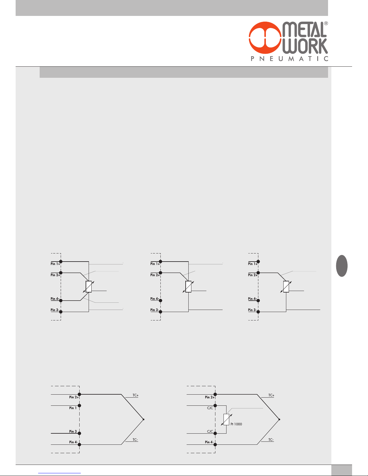
43
GB
3.3.6 M8 analogue 4-input module for temperature measurement
Each temperature measurement module S can handle up to 4 inputs that can be configured freely for the use of temperature sensors or
thermocouples of various type. They come with some individually configurable parameters.
Temperature compensation (CJC – Cold-Junction Compensation) for the use of thermocouples occurs internally, under normal ambient temperature
conditions, there is no need to install an external cold-Junction. The installation of an external sensor is recommended in case of sudden changes in
the ambient temperature. Use a PT1000 sensor, such as the TE Connectivity NB-PTCO-157 sensor or the equivalent.
The temperature measurement module sends the values read to the control system, with 2 input bytes for each channel.
Up to a total of 16 bytes per module starting from the IN byte 113.
Type of sensors supported
Pt 100, Pt 200, Pt 500, Pt 1000
Ni 100, Ni 120, Ni 500, Ni 1000
Type of connection with 2, 3, 4 wires
Type of thermocouple supported
J, E, T, K, N, S, B, R
3.3.6.1 Electrical connections of temperature sensors (Pt and Ni series)
Pin 1 = + Sensor power supply
Pin 2 = + Input signal, positive
Pin 3 = - Sensor power supply
Pin 4 = - Input signal, negative
Ring nut = Functional earthing
Each input has two pins for constant sensor feeding and two pins for sensor signal.
Connections with 2, 3 and 4 wires can be made depending on the desired degree of precision.
Maximum precision can be obtained with 4-wire connection.
4-wire connection 3-wire connection 2-wire connection
In general, only shielded cables must be used for the transmission of analogue signals.
Sensor feeding
Sensor feeding
Sensor signal
Sensor
Sensor feeding
Sensor signal
Sensor
Sensor feeding
Sensor feeding
Sensor signal
Sensor signal
Sensor
3.3.6.2 Electrical thermocouple connections
Pin 1 = CJC – Cold-Junction Compensation via external sensor Pt1000 (optional)
Pin 2 = V+ Input signal from sensor
Pin 3 = CJC - Cold-Junction Compensation via external sensor Pt1000 (optional)
Pin 4 = V- Input signal from sensor
Ring nut = Functional earthing
Standard connection – internal cold junction Connection with external Cold Junction – Optional
external cold junction
(optional)
Page 44
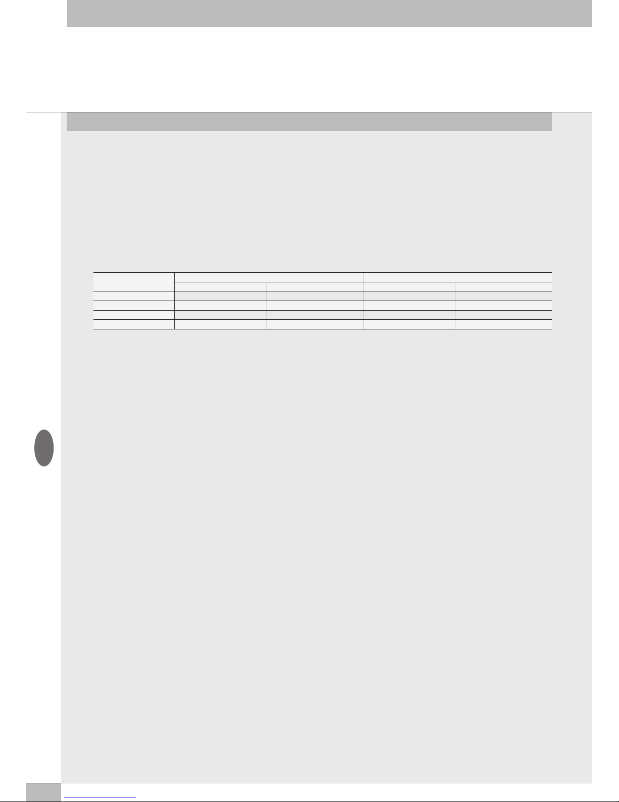
44
GB
3.3.6.3 Unit Parameters
Common parameters
• Unit of measurement from 0x8090.01 to 0x80A3.01 Unit of measure: temperature reading option °Celsius or °Fahrenheit
0x8090.01 = 0 °Celsius
0x8090.01 = 1 °Fahrenheit
• Noise suppression from 0x5F90.02 to 0x5F93.02 Noise rejection: suppresses electrical noise generated by mains electricity supply. This
parameter works in conjunction with the "Acquisition Filter" parameter.
0x8090.02 = 0 50 Hz: suppresses noise generated by 50Hz mains electricity supply
0x8090.02 = 1 60 Hz: suppresses noise generated by 60Hz mains electricity supply
0x8090.02 = 2 50/60 Hz slow: suppresses noise generated by 50Hz and 60Hz mains electricity supply.
A high level of filtering is achieved, but with a delay in data acquisition.
0x8090.02 = 3 50/60 Hz fast: suppresses noise generated by 50Hz and 60Hz mains electricity supply.
Very fast acquisition is achieved, but with a low level of filtering.
Noise suppression
Sync 3 Sync 4
Noise attenuation (dB) Data acquisition delay (ms) Noise attenuation (dB) Data acquisition delay (ms)
50 Hz 95 60 120 80
60 Hz 95 50 120 67
50/60 Hz Slow 100 300 120 400
50/60 Hz Fast 67 60 82 80
Channel Inputs
• Type of sensor from 0x8094.01 to 0x80A3.01 Sensor adjustment: possible choice of the type of sensor used among those available.
0x8094.01 = 0 No sensor connected
0x8094.01 = 1 Pt 100 (TK=0.00385)
0x8094.01 = 2 Pt 200 (TK=0.00385)
0x8094.01 = 3 Pt 500 (TK=0.00385)
0x8094.01 = 4 Pt 1000 (TK=0.00385)
0x8094.01 = 5 Pt 100 (TK=0.00391)
0x8094.01 = 6 Pt 200 (TK=0.00391)
0x8094.01 = 7 Pt 500 (TK=0.00391)
0x8094.01 = 8 Pt 1000 (TK=0.00391)
0x8094.01 = 9 Ni 100 (TK=0.00617)
0x8094.01 = 0A Ni 200 (TK=0.00617)
0x8094.01 = 0B Ni 500 (TK=0.00617)
0x8094.01 = 0C Ni 1000 (TK=0.00617)
0x8094.01 = 0D TC Type E
0x8094.01 = 0E TC Type J
0x8094.01 = 0F TC Type T
0x8094.01 = 10 TC Type K
0x8094.01 = 11 TC Type N
0x8094.01 = 12 TC Type S
0x8094.01 = 13 TC Type B
0x8094.01 = 14 TC Type R
• Type of connection (for RTD only) from 0x8094.02 to 0x80A3.02 Connection technology: possible choice of the type of sensor connection,
if with 2, 3 or 4 wires.
0x8094.02 = 0 2 wires
0x8094.02 = 1 3 wires
0x8094.02 = 2 4 wires
• Cold joint compensation (for TC only) from 0x8094.03 to 0x80 A3.03 Cold junction compensation: possible choice of an external cold joint
instead of the one already installed internally.
The external cold joint (Pt1000) is recommended in case of sudden changes in the ambient temperature.
0x8094.03 = 0 internal
0x8094.03 = 1 external
• Measurement resolution from 0x8094.04 to 0x80A3.04 Measure resolution: possible choice of measurement resolution in tenths or
hundredths of °C. The resolution in hundredths only applies to RTD sensors, with temperature reading of maximum +/- 327°C.
0x8094.04 = 0 0.1
0x8094.04 = 1 0.01
• Sensor disconnected signalling from 0x8094.05 to 0x80A3.05 Signaling disconnected sensor: if enabled, the breakage of a wire generates
an alarm.
0x8094.05 = 0 disabled
0x8094.05 = 1 enabled
Page 45

45
GB
• Short-circuit signalling (for RTD only) from 0x8094.06 to 0x80A3.06 Short circuit signaling: if enabled, a short circuit of the sensor
connection generates an alarm.
0x8094.06 = 0 disabled
0x8094.06 = 1 enabled
• Minimum value monitor from 0x8094.07 to 0x80A3.07 Lowest value: when this function is enabled, an alarm is generated when the
temperature falls below the set minimum value.
0x8094.07 = 0 disabled
0x8094.07 = 1 enabled
• Maximum value monitor from 0x8094.08 a 0x80A3.08 Highest value: when this function is enabled, an alarm is generated when the
temperature is above the set maximum value.
0x8094.08 = 0 disabled
0x8094.08 = 1 enabled
• Measured Value Filter from 0x8094.09 to 0x80A3.09 Filter measured value: a mathematical filter that ensures a more stable temperature
reading.
By setting a filter value on the sampling of the highest signal, improved reading stability is achieved but with a longer delay in data display.
0x8094.09 = 1 1 samples
0x8094.09 = 2 2 samples
0x8094.09 = 3 4 samples
0x8094.09 = 4 8 samples
0x8094.09 = 5 16 samples
0x8094.09 = 5 32 samples
0x8094.09 = 6 64 samples
• Minimum value from 0x8094.0A to 0x80A3.0A Lowest value
• Maximum value from 0x8094.0B to 0x80A3.0B Highest value
• Acquisition filter from 0x8094.0C to 0x80A3.0C Acquisition filter: it defines the type of digital filter. It works in conjunction with the "Noise
suppression" parameter.
By setting the Sync 4 filter, a level of filtering higher than the one with the Sync 3 filter is achieved, but with a longer delay in data acquisition.
0x8094.0C = 0 Sync3
0x8094.0C = 1 Sync4
Page 46
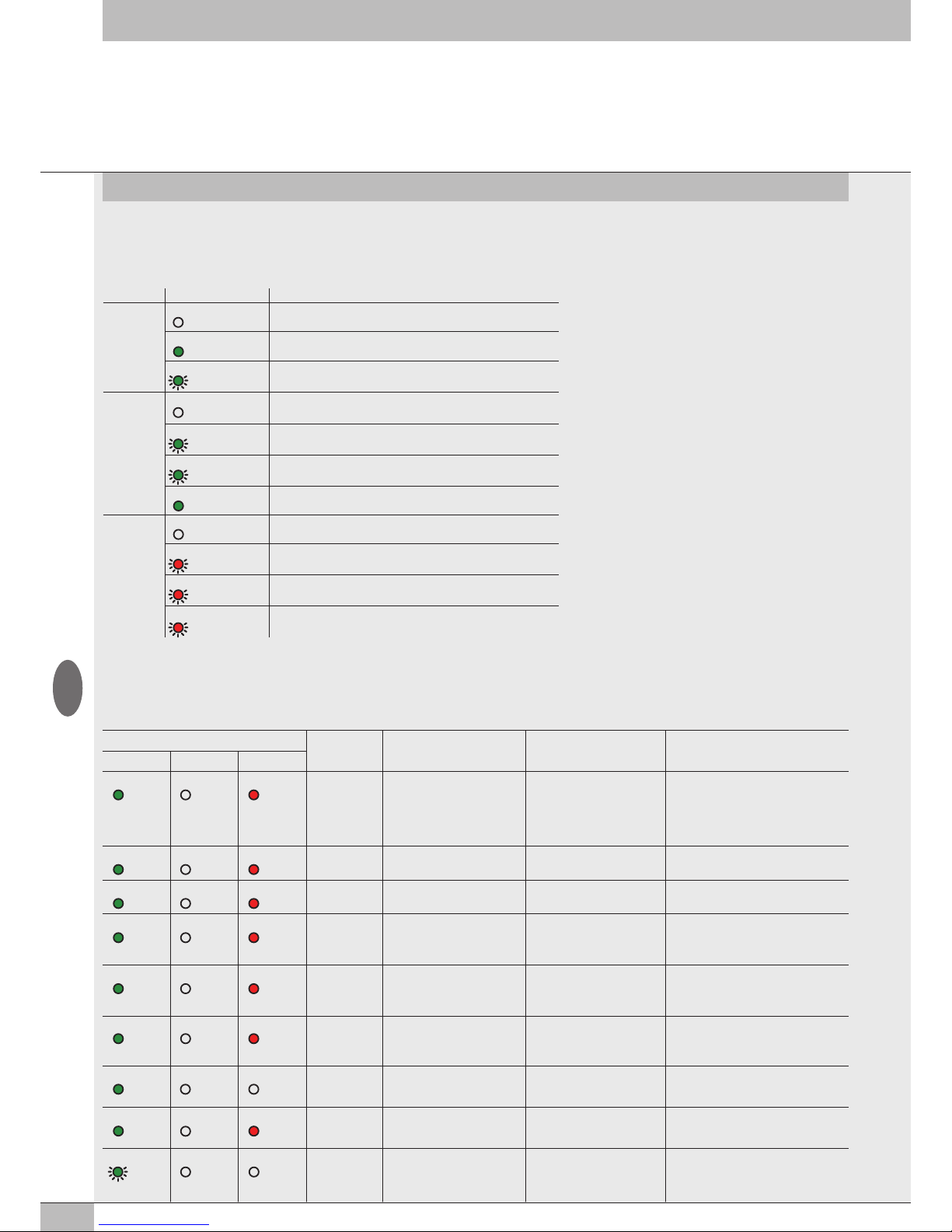
46
The diagnosis of the EB 80 EtherCAT system is defined by the state of the interface LED lights. Each component in the system relays its state, locally by
LED lights, and to the EtherCAT node by software messages.
4.1 EtherCAT NODE DIAGNOSTIC MODE
The diagnosis of the EB 80 EtherCAT system is defined by the state of the interface LEDs RUN, ERR e IN/OUT.
4. DIAGNOSTICS
Led S TATE Meaning
IN / OUT
link/act
OFF
No connection to EtherCAT
ON (green)
The device is connected to the network but there is no data exchange
GREEN The device communicates with the network
(flashing)
RUN
OFF
The device is in the INIT state
GREEN The device is in the PRE-OPERATIONAL state
(flashing)
GREEN The device is in the SAFE-OPERATIONAL state
(single flashing)
GREEN The device is in the OPERATIONAL state
ERR
OFF No error - the device is working properly
ON (red) Configuration error
(flashing)
ON (red) Watchdog error
(single flashing)
ON (red) Communication error: cable disconnected
(double flashing)
GB
4.2 EB 80 SYSTEM DIAGNOSTIC MODE – ELECTRICAL CONNECTION
Diagnosis of the EB 80 system - Electrical Connection - is defined by the state of Power, Bus Error and Local Error LED lights.
Diagnostic functions of the EB 80 system relay the state of the system via error codes in hexadecimal or binary format to the controller, in order of
priority. The state byte is interpreted by the controller as an input byte.
The table below shows the correct interpretation of the codes.
LED light state Hex code Meaning Notes Solution
Power Bus Error Local Error
ON (green) OFF ON (red)
0xFF
System limits exceeded,
comunication line data
overflow
Number of I/Os to be checked
simultaneously is too high or
the control frequency is too
high.
Modify the system by reducing the
number of I/Os to be checked
simultaneously.
Contact technical support
ON (green) OFF ON (red)
0xD4 ÷ 0xD7
fault with a temperature
analogue input module
• Sensor not connected
• Wrong parameters
Check the connection and the
parameters set
ON (green) OFF ON (red)
0xD0 ÷ 0xD3
Analogue input module not
calibrated
- Contact technical support
ON (green) OFF ON (red)
0xCC ÷ 0xCF
Fault with analogue output
or total module current
too high
Individual output fault/
module over-demand/
DAC errors
Turn off power supply and remove the
cause of failure
ON (green) OFF ON (red)
0xC8 ÷ 0xCB
Fault with analogue input
or total module current
too high
Under-overflow out of range
single input / over-absorption
of the module
Turn off power supply and remove the
cause of failure
ON (green) OFF ON (red)
0xB0 ÷ 0xC5
Digital output failure or total
current of module too high
Short-circuit of an individual
output / module overcurrent
Turn off power supply and remove the
cause of failure
ON (green) OFF OFF
0xA0 ÷ 0xAF
Overcurrent of a digital input Signalled by one input Turn off power supply and remove the
cause of failure
ON (green) OFF ON (red)
0x20 ÷ 0x9F
Valve 1 / 128 faulty
**
Solenoid pilot short-circuited,
interrupted or not connected
Turn off power supply and remove the
cause of failure
GREEN
(flashing)
OFF OFF
0x17
No auxiliary power - Insert auxiliary power supply
Page 47
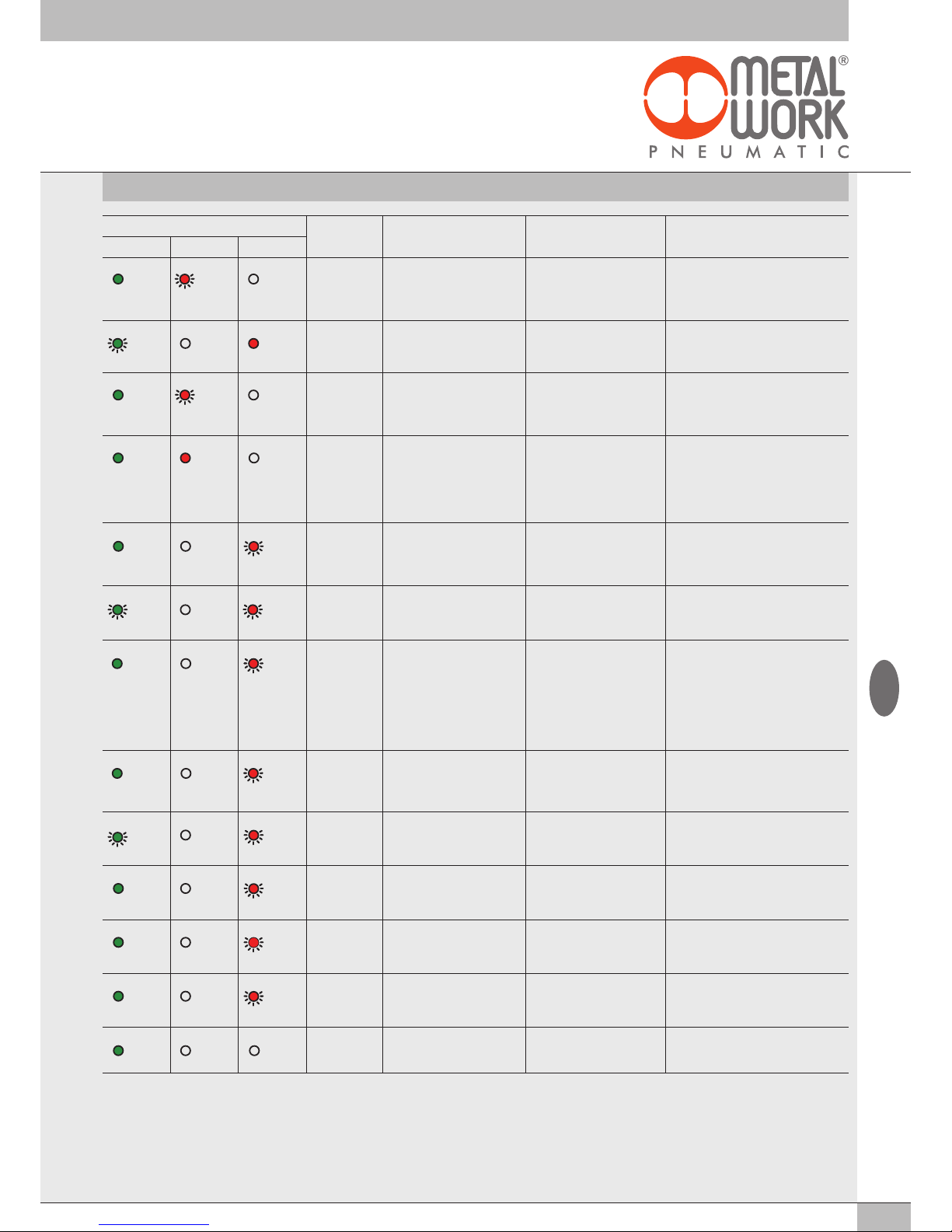
47
GB
** Proceed as follows to identify the position of the faulty valve:
Error code HEX – 0x20 = n
Convert the n code from hexadecimal to decimal. The resulting number corresponds to the faulty position. The positions where dummy or bypass valves are installed must also be
considered in the calculation. Codes are numbered from zero to 127. Code 0 corresponds to the first valve of the island.
For example: error code 0x20 n= 0x20 – 0x20 = 0x00
decimal value = 0 corresponding to the first valve (position) of the island.
error code 0x3F n= 0x3F – 0x20 = 1F
decimal value = 31 corresponding to the valve (position) 32
LED light state Hex code Meaning Notes Solution
Power Bus Error Local Error
ON (green) RED
(double
flashing)
OFF
0x16
Address / configuration of a
valve base or a signal module
error
Valve base or signal module
faulty
Turn off power supply and remove the
cause of failure
GREEN
(flashing)
OFF ON (red)
0x15
Power supply out of range
(Under/over-voltage)
- Power the system with a voltage within
the allowed range
ON (green) RED
(single
flashing)
OFF
0x14
Error in the configuration
parameters of a valve base or
a signal module
Current configuration not
corresponding to the one
stored in the device.
Repeat the configuration procedure.
If the error persists, replace the faulty
component.
ON (green) ON (red) OFF
0x10
EB 80 Net internal
communication faulty
Additional island configured
but not connected.
Connection between valve
bases faulty or incomplete
(blind end plate C is not
correct for the fieldbus).
Check the correct connection of the entire
system. Make sure the blind end plate
is of the type suitable for the fieldbus.
When the communication is restored,
the alarm rests automatically after 3
seconds.
ON (green) OFF RED
(single
flashing)
0x09
Error in configuring the head
parameters.
At least a value is wrong or
out-of-range.
-
GREEN
(flashing)
OFF RED
(flashing)
0x08
Number of solenoid pilots
connected to the network
greater than 128
- Restore correct configuration of the valve
bases, by removing any excess ones.
ON (green) OFF RED
(double
flashing)
0x07
Mapping error.
Number of connected valve
bases different from or greater
than the max. admissible
number.
Closing plate on S modules not
connected.
Current configuration not
matching the one stored in the
device.
The EB 80 Net network not
properly completed.
Turn off power supply. Restore the
correct configuration and repeat the
configuration procedure.
Turn off power supply, install the closing
plate using the terminal board provided
or insert the termination connector.
ON (green) OFF RED
(single
flashing)
0x06
Addressing error:
• type of module not allowed;
• no valve base or signal
module connected.
- Connect the valve bases or the signal
modules of the type allowed.
GREEN
(flashing)
OFF RED
(flashing)
0x05
Number of digital inputs
connected to the network
greater than 128
- Disconnect excess modules
ON (green) OFF RED
(flashing)
0x04
Number of digital outputs
connected to the network
greater than 128
- Disconnect excess modules
ON (green) OFF RED
(flashing)
0x03
Number of analogue inputs
connected to the network
greater than 16
- Disconnect excess modules
ON (green) OFF RED
(flashing)
0x02
Number of analogue outputs
connected to the network
greater than 16
- Disconnect excess modules
ON (green) OFF OFF
0x00
The system works properly - -
Page 48
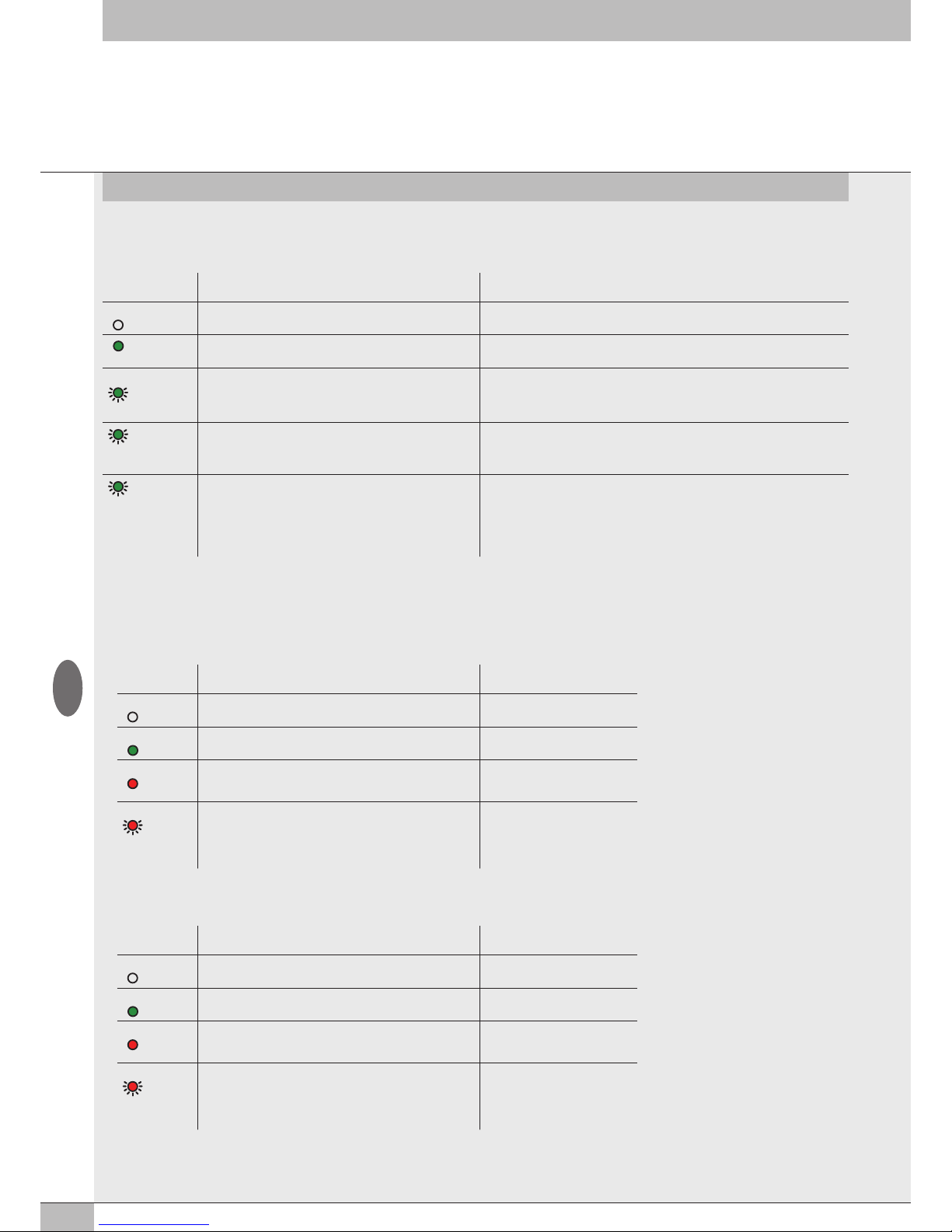
48
4.3 EB 80 SYSTEM DIAGNOSTIC MODE – VALVE BASE
The diagnosis of bases for valves is defined by the state of the interface Led lights.
The generation of an alarm activates a software electrical connection message with the code associated with the detected error.
Led Green
Base
Meaning FAULT signal output state and storage
OFF The output is not controlled. FAULT signal output – OFF
The output is active and works properly. FAULT signal output – OFF
ON
(double flashing)
Indication for each output.
Solenoid pilot interrupted or missing (dummy valve or valve with
a solenoid pilot installed on a base for two solenoid pilots).
FAULT signal output – Active
The output resets automatically when the cause of failure is removed.
The FAULT signal can only be reset by disconnecting the power supply.
(flashing)
Indication for each solenoid pilot output or base output
short-circuited.
FAULT signal output – Active, permanent
The output is turned off.
It can only be reset by disconnecting the power supply.
(flashing +
simultaneously flashing
of all Led
lights of the base)
Voltage out of range
Less than 10.8V or greater than 31.2V
Caution! Voltage greater than 32VDC irrevocably damages
the system.
FAULT signal output – Active, self-resettable to return within the operating range.
The alerts remain on 5 seconds after resetting.
4.4 EB 80 SYSTEM DIAGNOSTIC MODE – SIGNAL MODULES - S
The diagnosis of Signal Modules - S is defined by the state of the interface Led lights.
The generation of an alarm activates a software electrical connection message with the code associated with the detected error.
4.4.1 Diagnostic mode of Signal Modules - S – Digital Inputs
Led
X1..X8
Meaning Solution
OFF Input not active -
ON (green) Input active -
ON (red) Indication for each input.
Short-circuited or overloaded input.
Remove the cause of the fault
RED
(flashing + all Led
lights flashing
simultaneously)
Overall current input too high. Remove the cause of the fault
4.4.2 Diagnostic mode of Signal Modules - S – Digital Outputs
Led
X1..X8
Meaning Solution
OFF Output not active -
ON (green) The output is active and works properly. -
ON (red) Indication for each output.
Short-circuited or overloaded output.
Remove the cause of the fault
RED
(flashing + all Led
lights flashing
simultaneously)
Overall current input too high. Remove the cause of the fault
GB
Page 49
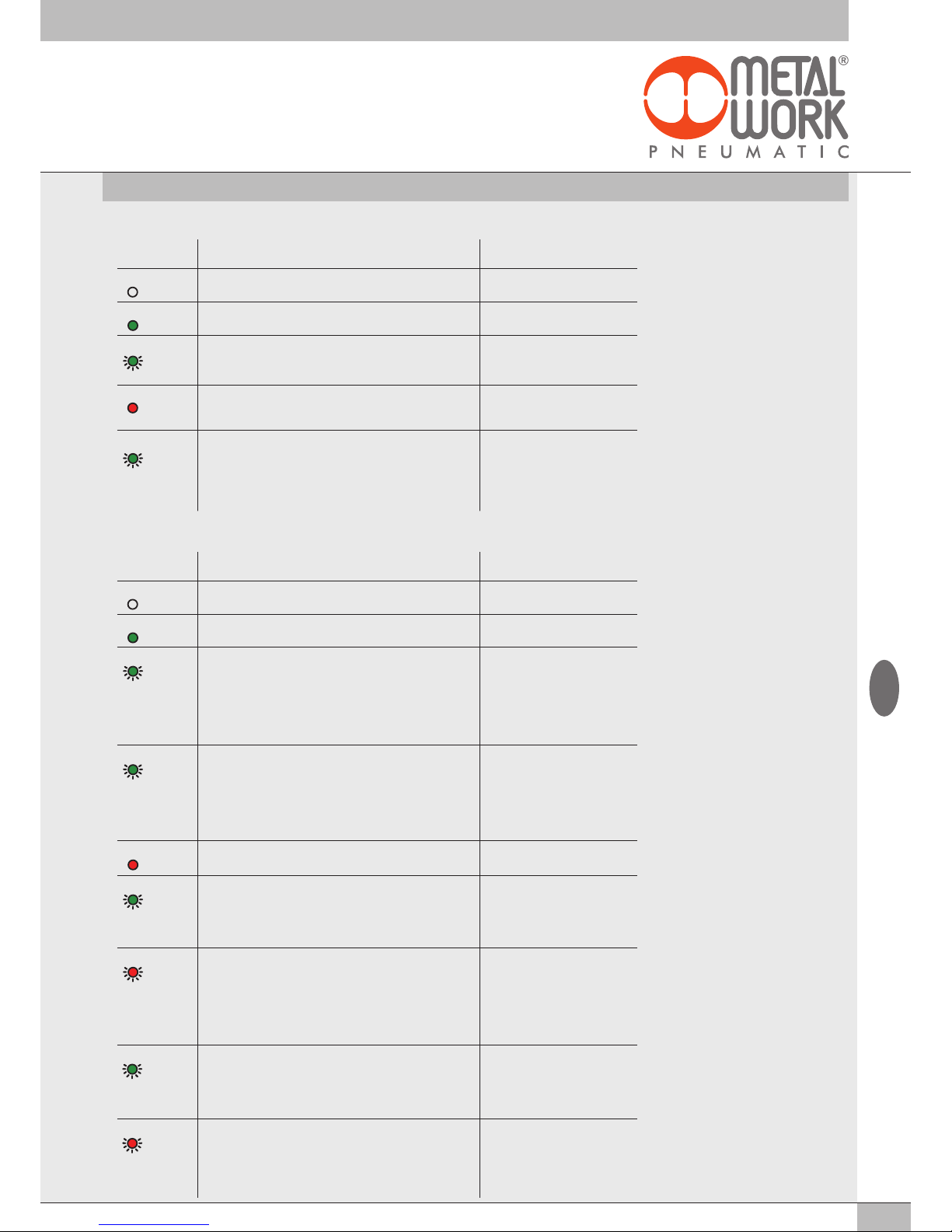
49
4.4.3 Diagnostic mode of Signal Modules - S – Analogue Inputs
Led
X1..X4
Meaning Solution
OFF Input not active -
ON (green) The input is active and works properly -
GREEN
(flashing)
Analogue signal outside permitted range Set input type correctly
Replace sensor with a
permitted type
ON (red) Analogue signal value too high/low Set input type correctly
Replace sensor with a
permitted type
GREEN
(simultaneously
flashing of all Led
lights of the base)
Overload or short circuit signal Remove the cause of the fault
4.4.4 Diagnostic mode of Signal Modules - S – Analogue Outputs
Led
X1..X4
Meaning Solution
OFF Output not active -
ON (green) The output is active and works properly -
GREEN
(all Led
lights flashing
simultaneously
T ON 0.2 sec
T OFF 1 sec )
Value of power supply voltage outside permitted range Power the module correctly
GREEN
(all Led
lights flashing
simultaneously
T ON 0.2 sec
T OFF 0.2 sec)
Power supply overload or short circuit signal Remove the cause of the fault
ON (red) All LEDs active simultaneously
Internal fault
Replace the module
GREEN
(flashing
T ON 0.6 sec
T OFF 0.6 sec)
Output overloaded or short circuited Remove the cause of the fault.
Disconnect the electricity supply to
reset the fault signal.
RED
(all Led
lights flashing
simultaneously
T ON 0.2 sec
T OFF 0.2 sec)
Module overtemperature Remove the cause of the fault
GREEN
(double flashing
T ON 0.6 sec
T OFF 1 sec )
Open circuit signal (For 4/20 mA or 1/5 V channels) Remove the cause of the fault
RED
(flashing
T ON 0.6 sec
T OFF 0.6 sec)
Value set not permitted. Remove the cause of the fault.
Disconnect the electricity supply to
reset the fault signal.
GB
Page 50
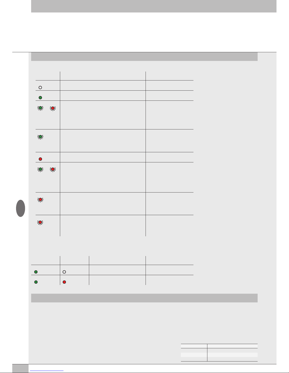
50
GB
5. CONFIGURATION LIMITS
No. of nodes Maximum cable length
70 30 m
50 40 m
10 50 m
4.5 EB 80 SYSTEM DIAGNOSTIC MODE – ADDITIONAL ELECTRICAL CONNECTION
The diagnosis of Additional Electrical Connection is defined by the state of the interface Led lights.
The generation of an alarm activates a software electrical connection message with the code associated with the detected error.
POWER BUS ERROR Meaning Solution
ON (green) OFF The additional island works properly -
ON (green) ON (red) Failure. For the correct identification, refer
to the error code or local diagnostics.
Turn off power supply and remove
the cause of failure
The EB 80 network can be configured by assembling the islands according to the requirements of the system in which it is mounted.
For the system to operate safely and reliably, it is important to keep to the constraints associated with the serial transmission system based on CAN
technology and use shielded, twisted cables with controlled impedance, supplied by Metal Work.
The system constraints are defined by the following parameters of the assembly:
• the number of valve bases (nodes)
• the number of signal modules (nodes)
• the number of Additional Electrical Connections (nodes)
• the length of connection cables.
A high number of nodes reduces the maximum length of connection cables, and vice versa.
4.4.5 Diagnostic mode of Signal Modules - S - Analogue Inputs for temperature measurement
Led
X1..X4
Meaning Solution
OFF Input not active -
ON (green) The input is active and works properly -
GREEN RED
(all Led
lights flashing
simultaneously
T ON 0.2 sec
T OFF 1 sec )
Value of power supply voltage outside permitted range Power the module correctly
GREEN
(flashing
T ON 0.2 sec
T OFF 0.2 sec)
Value lower than the value set
under: Minimum Value
Value higher than the value set
under: Maximum Value
Enter the correct values
ON (red) The connected sensor is short-circuited Remove the cause of the fault
GREEN RED
(all Led
lights flashing
simultaneously
T ON 0.5 sec
T OFF 0.5 sec )
Internal error Remove the cause of the fault.
If the error persists, replace the
module
RED
(flashing
T ON 0.2 sec
T OFF 0.2 sec)
Open circuit signal Remove the cause of the fault
RED
(flashing
T ON 0.6 sec
T OFF 0.6 sec)
Sensor out of range Remove the cause of the fault
Page 51
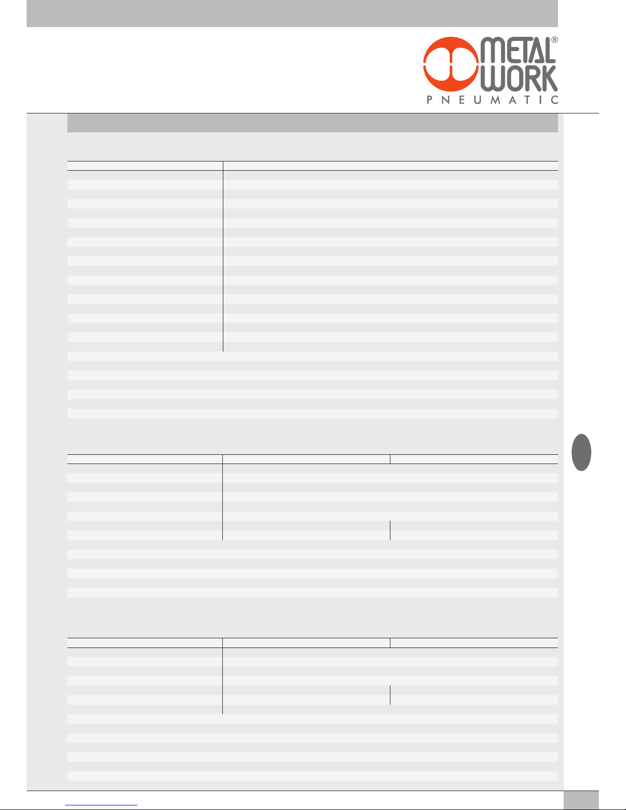
51
6. TECHNICAL DATA
6.1 EtherCAT ELECTRICAL CONNECTION
6.3 SIGNAL MODULES - S - DIGITAL OUTPUTS
TECHNICAL DATA 8 M8 Digital Outputs 16 Digital Input terminal board
Output voltage Corresponding to power voltage
Current for each connector mA max 500
Current for each module mA max 3000
Type of output Software-configurable PNP/NPN
Protection Overload and short-circuit protected inputs Overload and short-circuit protected outputs
Connections 8 M8 3-pole female connectors 4 connectors 12 pins with spring clamping
Input active signals One LED for each output
NB: Digital terminal block outputs are available from software version 1.37 and file ESI Metalwork_EB80_102O_145I
6.2 SIGNAL MODULES - S - DIGITAL INPUTS
TECHNICAL DATA 8 M8 Digital Inputs 16 Digital Inputs terminal board
Sensor supply voltage Corresponding to power voltage
Current for each connector mA max 200
Current for each module mA max 500
Input impedance kΩ 3.9
Type of input Software-configurable PNP/NPN
Protection Overload and short-circuit protected inputs
Connections 8 M8 3-pole female connectors 4 connectors 12 pins with spring clamping
Input active signals One LED for each input One LED for each output
NB: Digital terminal block inputs are available from software version 1.37 and file ESI Metalwork_EB80_102O_145I
GB
TECHNICAL DATA
Fieldbus 100 Mbit/S - Full-duplex - Supports auto-negotiation
Factory settings module denomination: EB80series
Addressing Automatic from the master depending on its topological position. Fixes with the second slave address function
Supply voltage range V 12 -10% 24 +30%
Minimum operating voltage V
10.8
*
Maximum operating voltage V 31.2
Maximum admissible voltage V
32
***
Protection Module protected from overload and polarity inversion. outputs protected from overloads and short-circuits.
Connections Fieldbus: 2 M12 F D encoding, internal switch. Power supply: M8, 4-PIN
Diagnostics EtherCAT: via local LED lights and software messages. Outputs: via local LED lights and state bytes
Bus power supply current absorption nominal Icc 180 mA at 24 V
Maximum number of pilots 128
Maximum number of digital inputs 128
Maximum number of digital outputs 128
Maximum number of analogue inputs 16
Maximum number of analogue outputs 16
Maximum number of inputs for temperatures 16
Data bit value 0 = non-active; 1= active
State of outputs in the absence of communication Configurable for each output: non-active, holding of the state, setting of a preset state
*
Minimum voltage 10.8V required at solenoid pilots. Check the minimum voltage at the power supply output using the calculations shown on page 31
*** IMPORTANT! Voltage greater than 32VDC will damage the system irreparably.
Page 52
52
6.4 SIGNAL MODULES - S - DIGITAL OUTPUTS + ELECTRICAL POWER SUPPLY
TECHNICAL DATA 6 M8 Digital Outputs + Electrical power supply
Supply voltage range V 12 -10% 24 +30%
Minimum operating voltage V
10.8
*
Maximum operating voltage V 31.2
Maximum admissible voltage V
32
***
Output voltage Corresponding to power voltage
Current for each connector mA max 1000
Current for each module mA max 4000
Type of output Software-configurable PNP/NPN
Protection Overload and short-circuit protected inputs
Connections 6 M8 3-pole female connectors for Signals
1 M8 4-pole male connector for Supply
Input active signals One LED for each input
* Minimum voltage 10.8V required at solenoid pilots. Check the minimum voltage at the power suply output using the calculations see page 31.
*** IMPORTANT! Voltage greater than 32VDC will damage the system irreparably.
6.5 SIGNAL MODULES - S - ANALOGUE INPUTS
TECHNICAL DATA 4 M8 Analogue Inputs
Sensor supply voltage Corresponding to power voltage
Current for each connector mA max 200
Current for each module mA max 650
Type of input, software configurable 0/10 V; 0/5 V; +/-10 V; +/-5 V; 4/20 mA; 0/20 mA
Protection Overload and short-circuit protected inputs
Connections 4 M8 4-pin female connectors
Local diagnostic signal via LED Overload, short-circuit or type of input
not complying with the configuration
Digital convert resolution 15 bit + prefix
6.6 SIGNAL MODULES - S - ANALOGUE OUTPUTS
TECHNICAL DATA 4 M8 Analogue Output
Supply voltage for devices Corresponding to power voltage
Current for each connector mA max 200
Current for each module mA max 650
Type of output 0/10 V; 0/5 V; +/-10 V; +/-5 V; 4/20 mA; 0/20 mA
Protection Overload and short-circuit protected outputs
Connections 4 M8 4-pole female connectors
Local diagnostic signal via LED Overload, short-circuit or type of connection
not complying with the configuration
Digital convert resolution 15 bit + prefix
GB
Page 53

53
Full compliance with EtherCAT specifications
EB 80 EtherCAT electrical connection has successfully passed the conformance testing using the EtherCAT Conformance Test Tool (CTT version 2.040.0)
EtherCAT
®
is a registered trademark and patented technology, licensed by Beckhoff Automation GmbH, Germany.
www.metalwork.eu
EQZZZZ004 ITA_GB - IM06_06/2018
TECHNICAL DATA 4 M8 analogue Inputs for temperature measurement
Sensors supply voltage Corresponding to the supply voltage
Maximum input voltage VDC 30
Sensor type (RTD)
platinum (-200 to +850°C) Pt100, Pt200, Pt500, Pt1000 (TK = 0.00385
and
TK = 0.00391)
nichel (-60 to +180°C) Ni100, Ni120, Ni500, Ni1000 (TK = 0.00618)
Connections type (RTD) 2, 3 or 4-wire
Type of thermocouple (TC) J, E, T, K, N, S, B, R
Cold junction compensation for thermocouples
internal With internal electronic sensor
external An external PT 1000 sensor connected to the M8 connector of the thermocouple is needed
Temperature range °C – 200 to + 800
°F – 328 to + 1472
Digital convert resolution 15 bit + prefix
Max error compared to ambient temperature ±0.5%
(TC)
±0.06%
(RTD)
Max. basic error (ambient T 25°C) ±0.4% (TC)
°C ±0.6 (with 4-wire RTD with 0.1 resolution)
°C ±0.2 (with 4-wire RTD with 0.01 resolution)
Repeatability (ambient T 25°C) ±0.03%
Address employment 2 bytes for each input - 8 bytes per module
Cycle time (module) ms 240
Software linearization
for RTD Piecewise linear approximation
for TC NIST (National Institute of Standards and Technology) Linearization based on
ITS-90 scale (International Temperature Scale of 1990) for the thermocouple linearization
Maximum length of shielded cable m < 30
for the connection
Diagnostics One LED for each input and reporting to the Master
NB: Are available from software version 1.37 and file ESI Metalwork_EB80_102O_145I
6.7 SIGNAL MODULES - S - ANALOGUE INPUTS FOR TEMPERATURE MEASUREMENT
NOTES
GB
 Loading...