

Metalux IL519006EN Installation Instructions
INS #
Brand Logo
reversed out of
black
INS #
IL519006EN
Installation Instructions – ILED Retrofit Kit
Instructions d’installation – Trousse de modernisation DEL
Instrucciones de instalación – kit adaptador ILED
WARNING
Risk of fire, electrical shock, cuts and or other casualty
hazards. This product must be installed in accordance
with the applicable installation code by a qualified
electrician or a person familiar with the construction
and operation of the product and the hazards
involved. Cooper Lighting Solutions assumes no
responsibility for claims brought about by improper or
careless installation or handling of this product.
WARNING
Risk of fire or electric shock. Luminaire wiring and
electrical parts may be damaged when drilling for
installation of LED retrofit kit. Check for enclosed
wiring and components.
WARNING
Risk of fire or electric shock. LED Retrofit Kit
installation requires knowledge of luminaires electrical
systems. If not qualified, do not attempt installation.
Contact a qualified electrician.
WARNING
Risk of fire or electric shock. Install this kit only
in luminaires that have the construction features
and dimensions shown in the photographs and/or
drawings and where the input rating of the retrofit kit
does not exceed the input rating of the luminaire.
Only those open holes indicated in the photographs
and/or drawings may be made or altered as a result of
kit installation. Do not leave any other open holes in
an enclosure of wiring or electrical components.
WARNING
To prevent wiring damage or abrasion, do not expose
wiring to edges of sheet metal or other sharp objects.
“SUITABLE FOR OPERATION IN AMBIENT NOT
EXCEEDING 45°C” (For Retrofit kit with input wattage
less than or equal 115 Watts)
“SUITABLE FOR OPERATION IN AMBIENT NOT
EXCEEDING 40°C” (For Retrofit kit with input wattage
greater than 115 Watts)
WARNING
Risk of Fire and Electric Shock. If not qualified, consult
an electrician.
CAUTION
Risk of burn. Disconnect power and allow fixture to cool
before changing bulb or handling fixture.
CAUTION
Edges May Cut. Handle with care.
NOTICE: Green ground screw provided in proper location.
Do not relocate.
NOTICE: Minimum 90° supply conductors.
ote:N Specifications and dimensions subject to change
without notice.
IMPORTANT: Read carefully before installing fixture. Retain for future reference.
ATTENTION Receiving Department: Note actual fixture description of any shortage or noticeable damage on delivery
receipt. File claim for common carrier (LTL) directly with carrier. Claims for concealed damage must be filed within 15
days of delivery. All damaged material, complete with original packing must be retained.
COOPER LIGHTING SOLUTIONS IL519006EN Installation instructions
Installation Instructions – ILED Retrofit Kit
Tools Required
Cordless Drill, 1/8” Drill Bit and 1/4” Hex Driver.
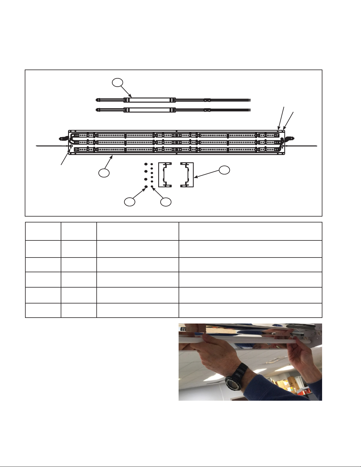
2
Tray
Mounting
Holes (I5)
Tray
Mounting
Holes (I8)
Tether
Mounting
Holes
Item
Number
Quantity Description Notes
1
4 5
1 1 LED Tray
2 See Note LED Driver
The number of LED boards on tray varies depending on
lumen requirements
Quantity (either 1 or 2) varies depending on wattage
requirements
3
3 2 Spacer Spacers are only required when used in “I8” fixtures
4 See Note
#8 Hex Washer Head Screws
(Gold)
5 6 #8 Hex Washer Head Screws
Quantity (either 2 or 4) varies depending on number of
drivers used
2 Screws required to mount tethers T housing
4 Screws are required to mount tray to housing
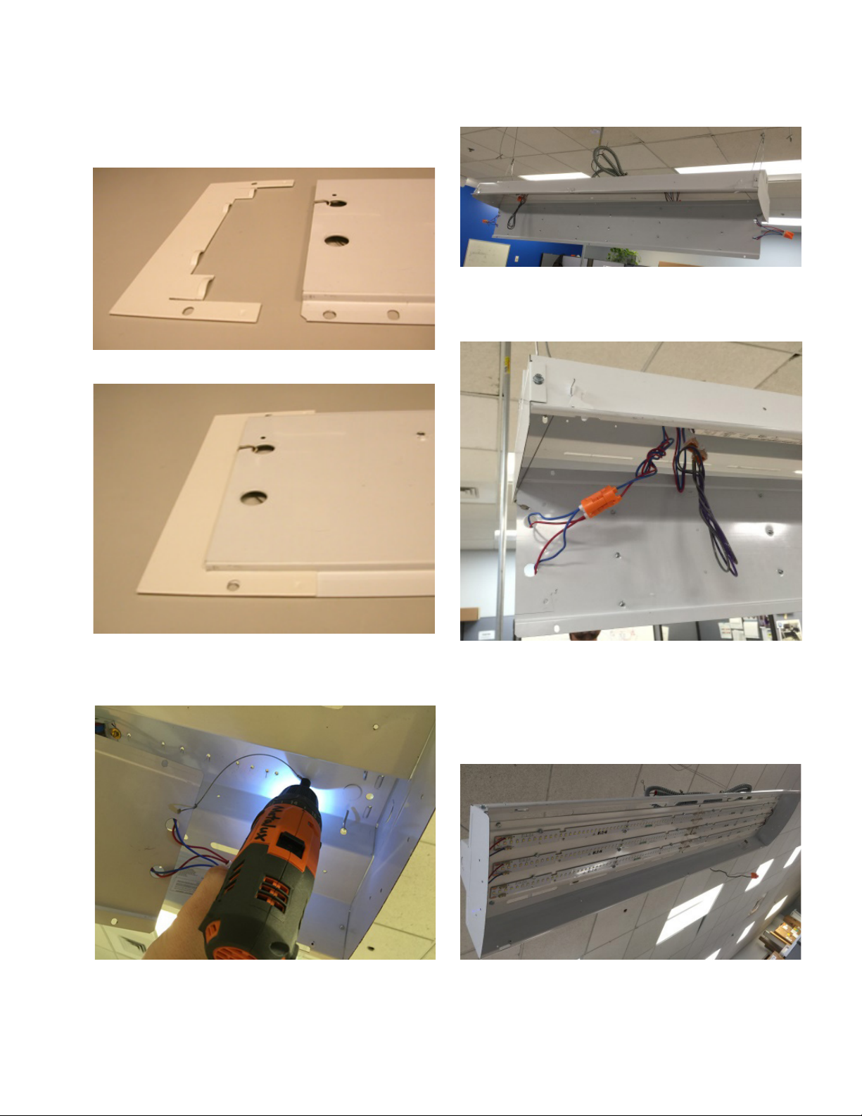
INSTALLATION
1. Turn off main power to fixture and remove lamps.
(Figure 1.)
2
Figure 1.
COOPER LIGHTING SOLUTIONS IL519006EN Installation instructions
Installation Instructions – ILED Retrofit Kit
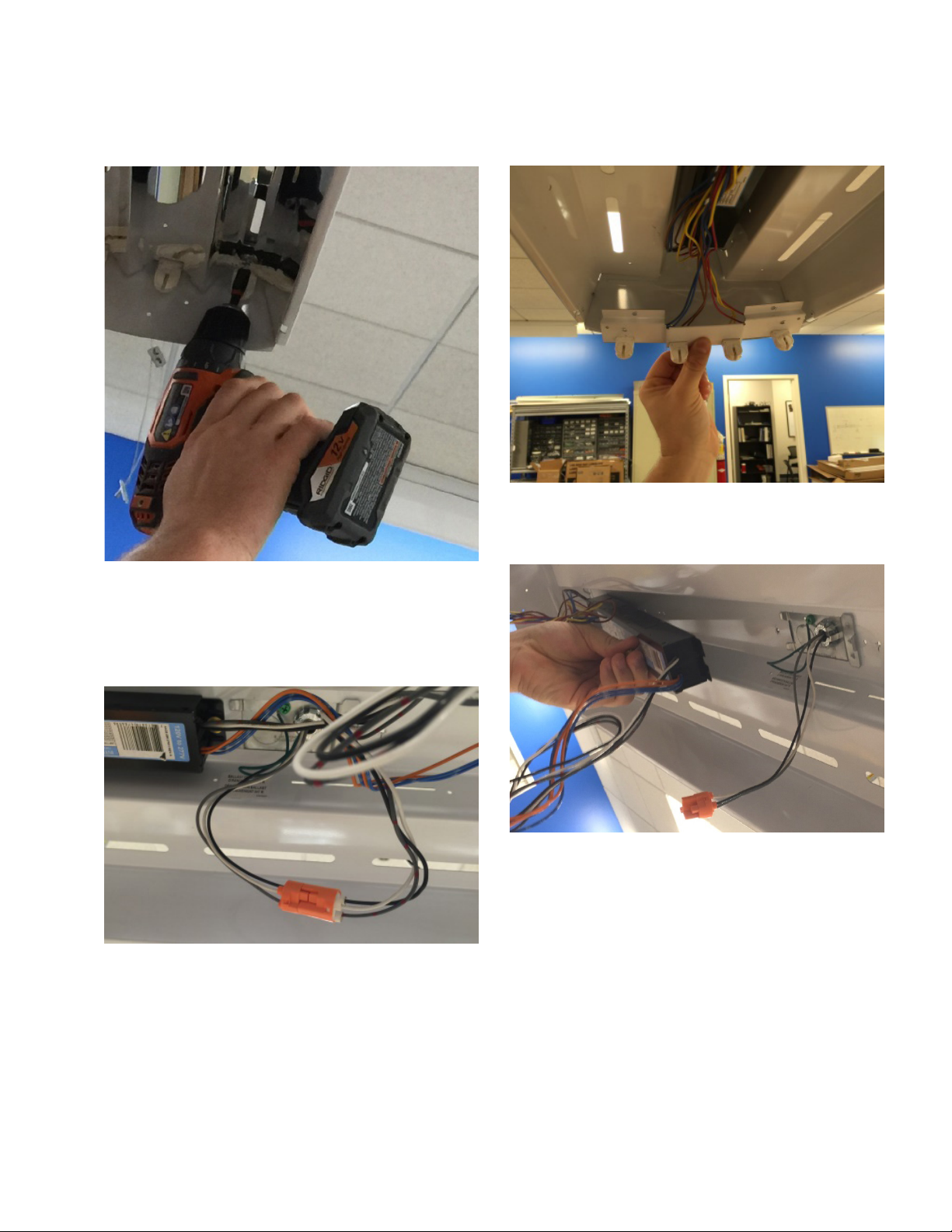
2. Remove reflector. (Figure 2.)
Figure 2.
3. Disconnect ballast from branch circuit. (Figure 3.)
Please check if supply conductors are rated 90C,
otherwise supply conductors shall be routed away from
heat-producing LED drivers and LEDs by following
(step no. 9d).
4. Remove socket tracks screws. (Figure 4.)
Figure 4.
5. Remove ballast and socket tracks including all lamp
holders and associated wiring. (Figure 5.)
Figure 3.
Figure 5.
3
COOPER LIGHTING SOLUTIONS IL519006EN Installation instructions
Installation Instructions – ILED Retrofit Kit
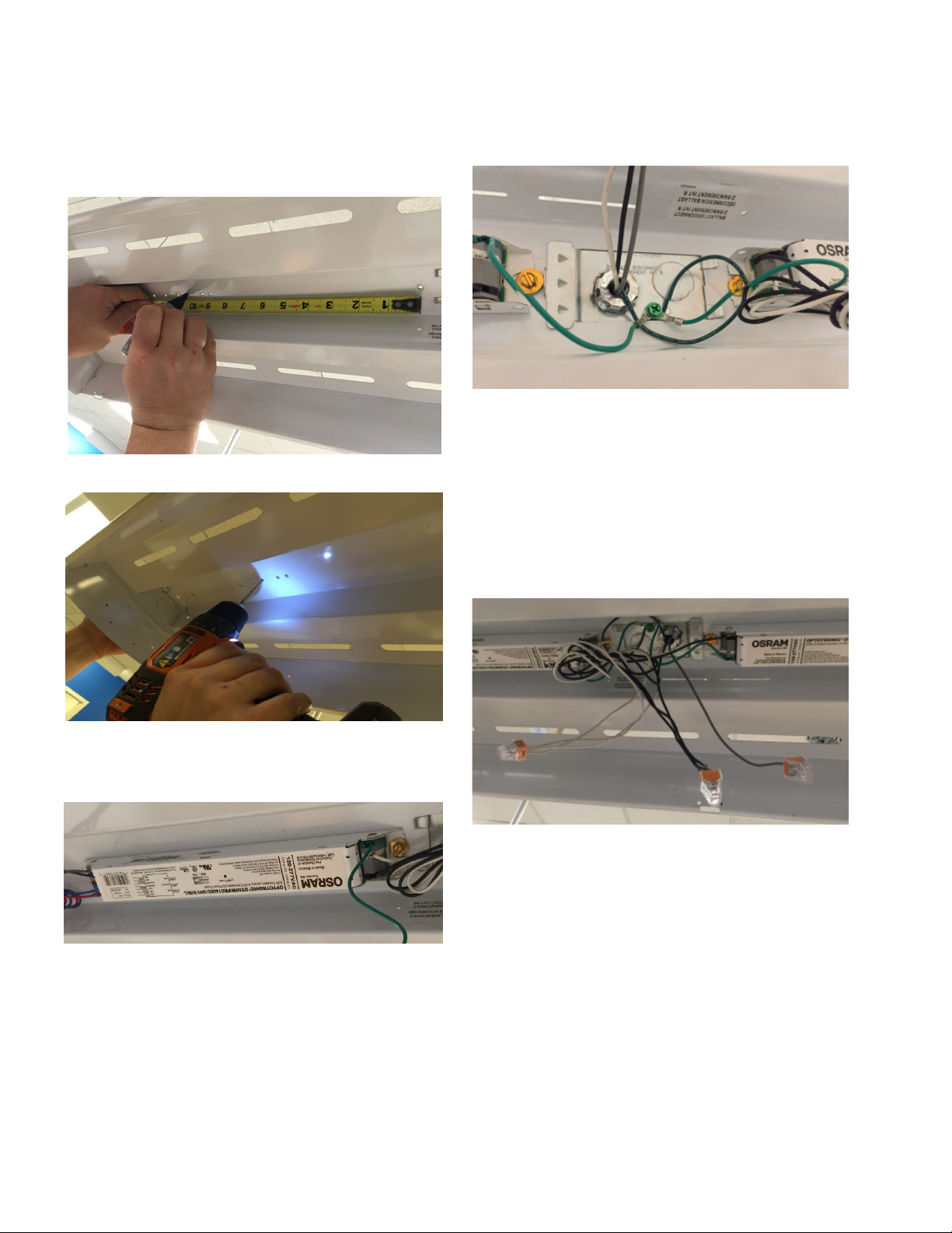
(Figure 6A). Drill driver mounting hole using 1/8” drill
bit. (Figure 6B.)
Figure 6A.
8. Install green ground wire(s) provided. (Figure 8.)6. Mark driver mounting hole(s) 10.5” from center
Figure 8.
9. Connect hot (black) and neutral (white) leads per
application requirement. (Figure 9.)
If second switched hot is present, connect to second
driver or cap off.
Where applicable, connect dimming circuit.
Route wiring inside wireway.
Route supply conducuctors away from heat generating
components such as LED driver, etc.
Figure 6B.
7. Install driver(s) using #8 hex washer head gold colored
thread forming screws provided. (Figure 7.)
Figure 7.
4
Figure 9.
COOPER LIGHTING SOLUTIONS IL519006EN Installation instructions
Installation Instructions – ILED Retrofit Kit
For I8 T8 Lamp Fixtures only
10. Install spacer plate to each end of LED tray.
Figure 10A.
Figure 11B.
12. Connect LED tray module to driver quick disconnects.
(Figure 12.)
Figure 10B.
11. Attach tethers to the outermost holes in the housing.
(Figure 11A. & Figure 11B.)
Figure 11A.
Figure 12.
13. Route wires inside wireway and attach LED tray using
(4) #8 slotted hex washer head screws provided.
(Figure 13.)
ote:N Do not pinch wires between LED tray and
housing.
Figure 13.
5
 Loading...