

Metalux IB519017EN Installation Instructions
INS #
Brand Logo
reversed out of
black
INS #
IB519017EN
Installation Instructions – WaveStream Linear
Instructions d’installation - Luminaire WaveStream
Instrucciones de instalación – Accesorio lineal WaveStream
WARNING
of fire, electrical shock, cuts and or other casualty
Risk
hazards. This product must be installed in accordance
with the applicable installation code by a qualified
electrician or a person familiar with the construction
and operation of the product and the hazards
involved. Cooper Lighting Solutions assumes no
responsibility for claims brought about by improper or
careless installation or handling of this product.
WARNING
Risk of Fire and Electric Shock. If not qualified, consult
an electrician.
IMPORTANT: Read carefully before installing fixture. Retain for future reference.
ATTENTION Receiving Department: Note actual fixture description of any shortage or noticeable damage on delivery
receipt. File claim for common carrier (LTL) directly with carrier. Claims for concealed damage must be filed within 15
days of delivery. All damaged material, complete with original packing must be retained.
Table of Contents
4 Ft. And 8 Ft. – Standalone Installation .............................................................................................................. 1-4
4 Ft. And 8 Ft. – Continuous Row Installation .................................................................................................... 5-6
Emergency Installation – End or Middle of Row ................................................................................................ 7-8
Occupancy/Daylight harvesting sensor installation – end or middle of row ...................................................... 9-10
Risk of burn. Disconnect power and allow fixture to cool
before changing bulb or handling fixture.
Edges May Cut. Handle with care.
NOTICE: Green ground screw provided in proper location.
Do not relocate.
NOTICE: Minimum 90° supply conductors.
ote:N Specifications and dimensions subject to change
without notice.
CAUTION
CAUTION
INSTALLATION
4FT Stand Alone Fixture Section (Step 1-7)
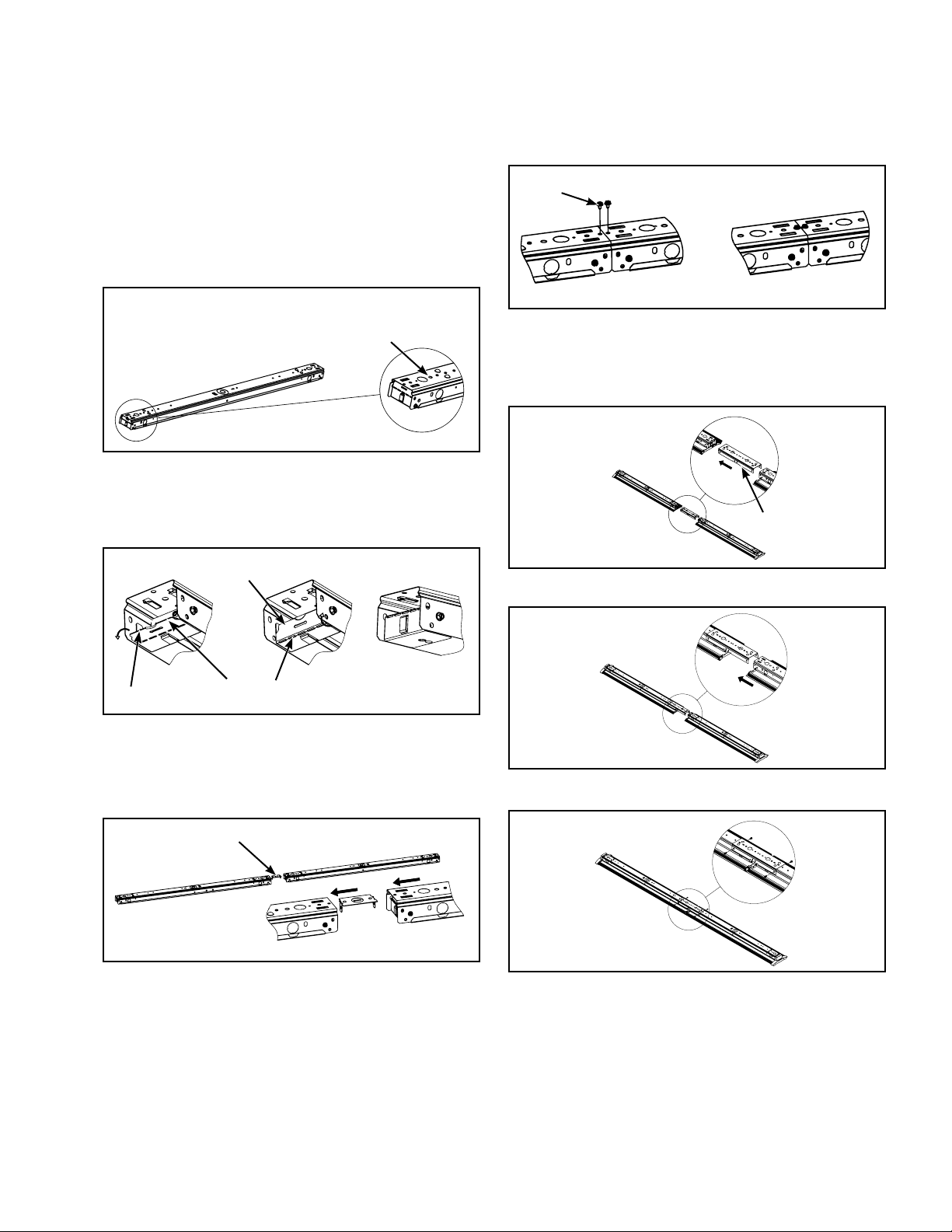
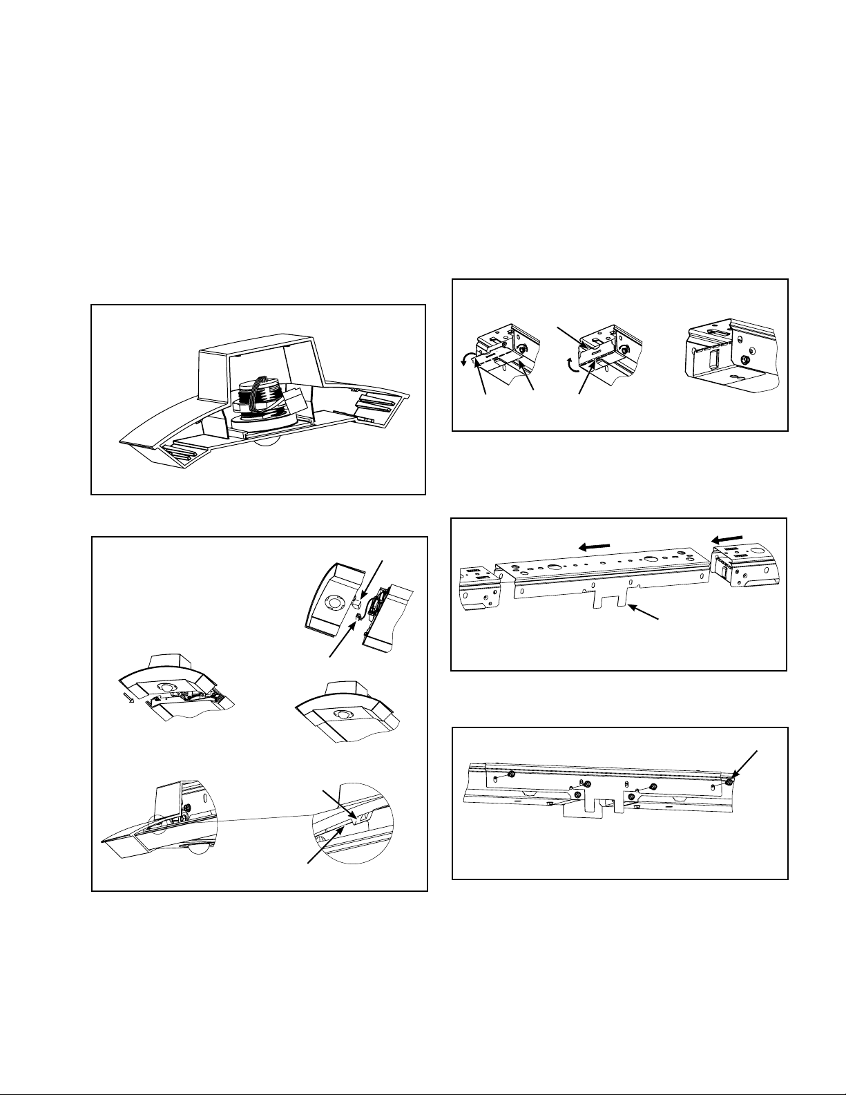
1. Remove channel assembly from box, remove tape
around channel cover and install on surface or
suspended ceiling according to code (hardware
provided by others). (Figure 1.)
Figure 1.
Openings at both ends
can be used for surface
mounted or suspended
applications
COOPER LIGHTING SOLUTIONS IB519017EN Installation instruction
Installation Instruc tions – WaveStream Linear
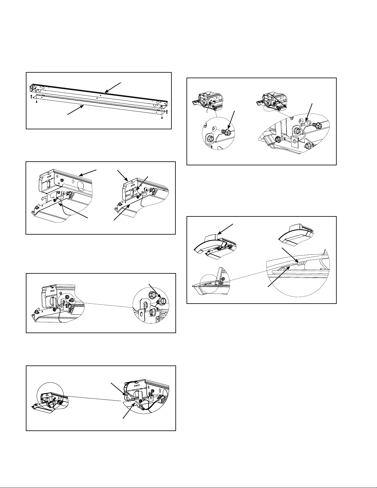
2. Wire fixture according to code and install channel cover
to channel with provided screws. (Figure 2.)
Channel
Channel
Cover
Figure 2.
3. Remove the waveguide assembly from the box and
slide it into the channel assembly.
6. To install safety cable remove screw from channel
assembly and reattach safety cable with the same
screw. (Figure 6.)
Safety
Cable
Screw
Channel
Assembly
Waveguide
assembly
Slide
Figure 3.
4. Secure the waveguide assembly to channel assembly
with screws provided, Figure 4. (One side of the fixture
only) (Use a long bit or right angle tool).
Screw
Figure 4.
5. Connect LED wire harness on each end of the
waveguide assembly. (Figure 5.)
Figure 6.
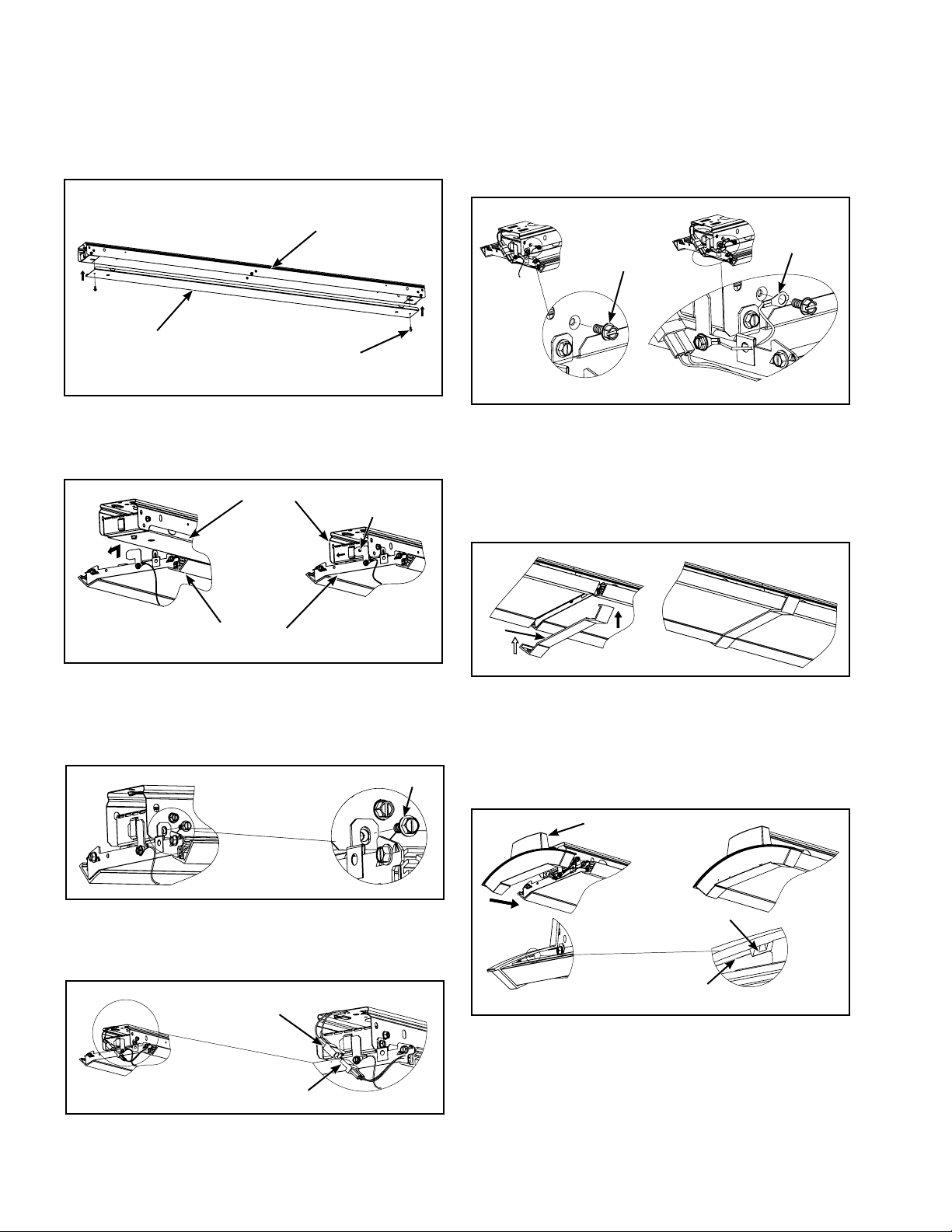
7. Remove protective film from the waveguide. Remove
endcaps from parts box, install Endcap to fixture.
Tuck wire harnesses and safety cable while installing.
Endcap tabs must fully engage in the metal bracket.
(Figure 7.)
Endcap
Endcap Tab
Sheet metal
Bracket in
Waveguide
Figure 7.
Fixture harness
Waveguide assembly harness
Figure 5.
2
COOPER LIGHTING SOLUTIONS IB519017EN Installation instructions
Installation Instruc tions – WaveStream Linear
8 ft. – Standalone Installation
1. Remove channel assembly from box, remove tape
around channel cover and install on surface or
suspended ceiling according to code (hardware
provided by others).
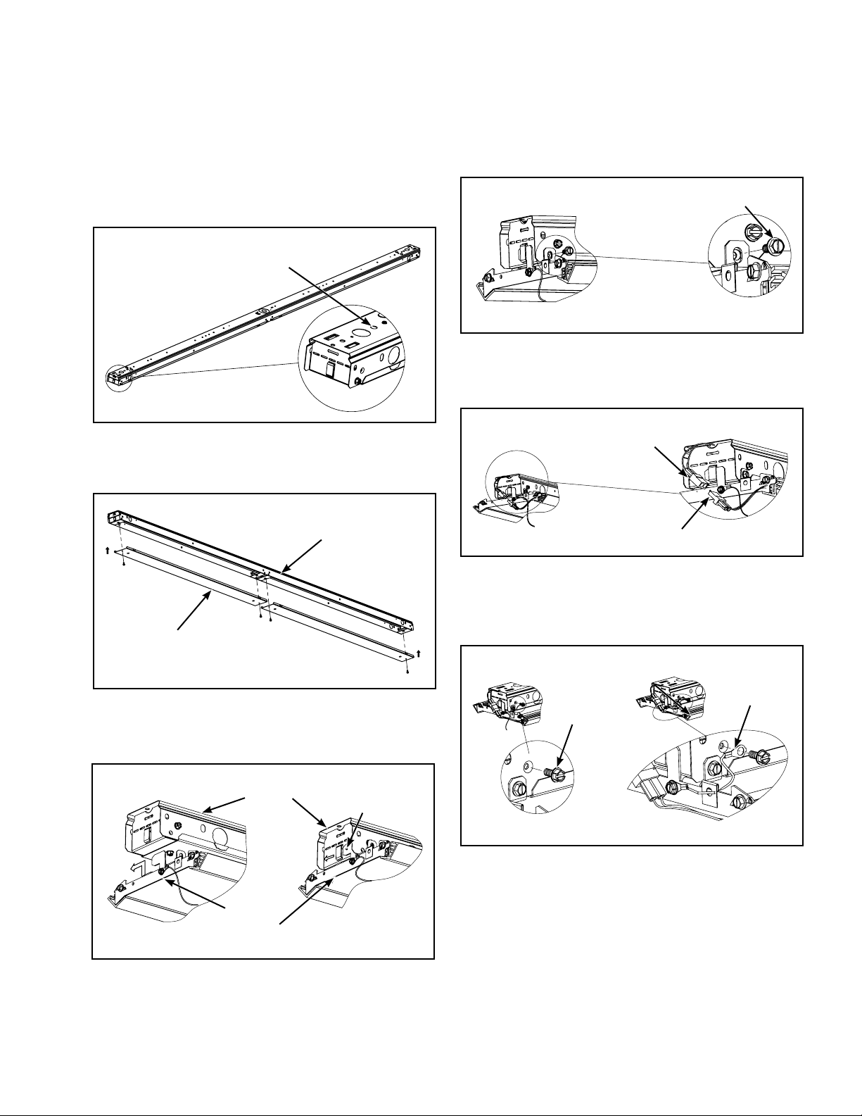
Openings at both ends can
be used for surface mounted
or suspended applications
4. Secure the waveguide assembly to channel assembly
with screws provided, (Figure 11.) (One side of the
fixture only) (Use a long bit or right angle tool).
Screw
Figure 11.
5. Connect LED wire harness on each end of the
waveguide assembly. (Figure 12.)
Figure 8.
2. Wire fixture according to code and install channel cover
to channel with provided screws. (Figure 9.)
Channel
Channel Cover
Figure 9.
3. Remove the waveguide assembly from the box and
slide it into the channel assembly.
Channel
Assembly
Slide
Fixture harness
Waveguide assembly harness
Figure 12.
6. To install safety cable remove screw from channel
assembly and reattach safety cable with the same
screw. (Figure 13.)
Safety
Cable
Screw
Waveguide
assembly
Figure 10.
Figure 13.
3
COOPER LIGHTING SOLUTIONS IB519017EN Installation instruction
Installation Instruc tions – WaveStream Linear
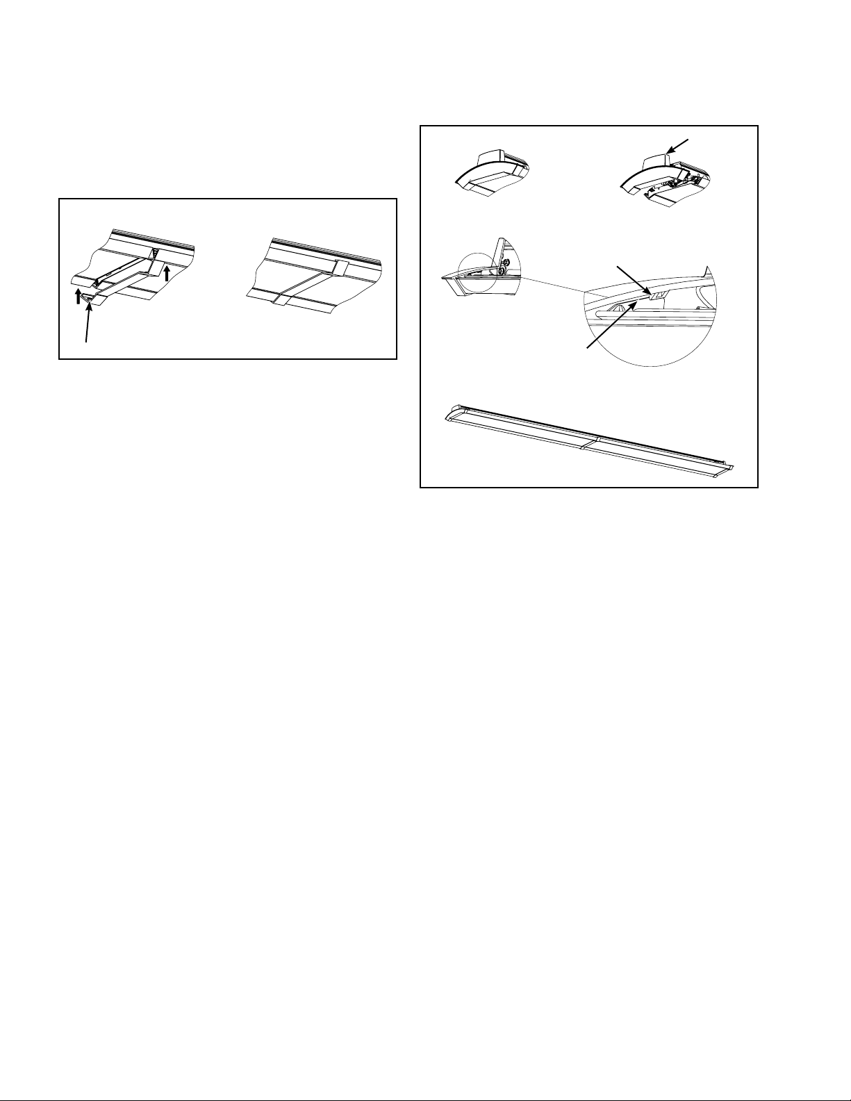
7. For 8ft fixture two sets of waveguide assemblies are
included. Repeat steps 3 to 6.
8. Remove protective film from the waveguide. Install Trim
provided, between waveguides. (Figure 14.)
Endcap
Endcap Tab
Row trim
Figure 14.
9. Tuck wire harnesses between waveguides.
10. Remove endcaps from parts box, install Endcap to
fixture. Tuck wire harnesses and safety cable while
installing. Endcap tabs must fully engage in the metal
bracket. (Figure 15.)
Sheet metal
Bracket in
Waveguide
Figure 15.
4
COOPER LIGHTING SOLUTIONS IB519017EN Installation instructions
Installation Instruc tions – WaveStream Linear
4 ft. and 8 ft. – Continuous Row Installation
Row Mount Installation Section (Step 1-12)
1. Remove channel assembly from box, remove
tape around channel cover and install in surface
or suspended ceiling according to code (hardware
provided by others).
Openings at both ends
can be used for surface
mounted or suspended
applications
Figure 16.
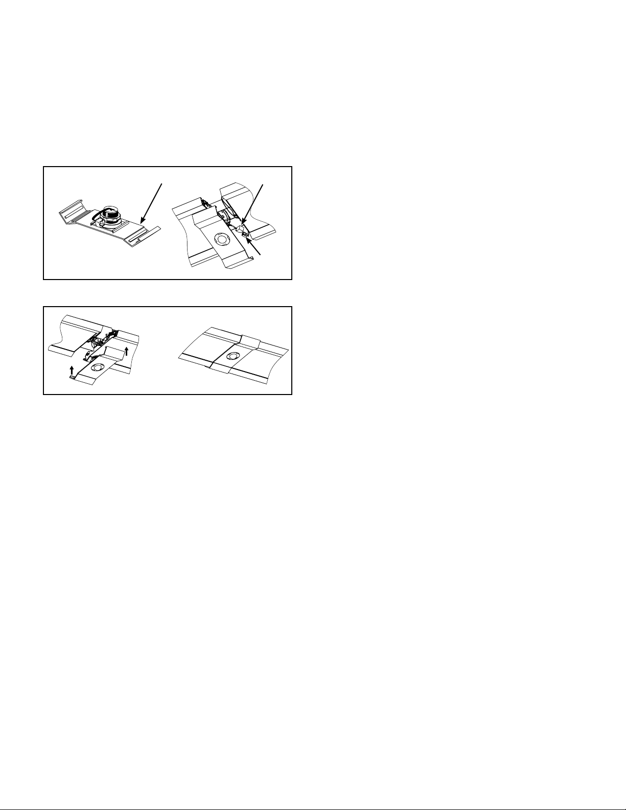
2. Rotate upper endplate, bend flange as shown and
rotate back to its original position in the Channel
assembly. (Figure 17.)
Flange
4. Install screws to secure row aligner.
Screws
Figure 19.
Optional: Special rigid channel connector designed to give
extra support to continuous channel installation. Provision
for hanging device
Long Connector
Figure 20.
Flange
Endplate
Figure 17.
3. Insert row aligner to one of the channels and insert
another channel to the other end of row aligner.
(Figure 18.)
Row Aligner
Figure 18.
Figure 21.
Figure 22.
5
COOPER LIGHTING SOLUTIONS IB519017EN Installation instruction
Installation Instruc tions – WaveStream Linear
5. Wire fixture according to code and install channel cover
to channel with provided screws. (Figure 23.)
Channel
9. To install safety cable remove screw from channel
assembly and reattach safety cable with the same
screw. (Figure 27.)
Safety Cable
Screw
Channel Cover
Screw
Figure 23.
6. Remove waveguide assembly from box and slide it into
the channel assembly.
Channel
Assembly
Waveguide
assembly
Slide
Figure 24.
7. Secure the waveguide assembly to channel assembly
with screws provided, (Figure 25.) (One side of the
fixture only) (Use a long bit or right angle tool).
Screw
Figure 27.
10. For 8ft fixture two sets of waveguide assemblies are
included. Repeat steps 6 to 9.
11. Remove protective film from waveguides and tuck wire
harness between waveguides. Install Trim provided,
between waveguides.
Row
Trim
Figure 28.
For End of Row Section (Step 12)
12. Remove endcaps from parts box, install Endcap to
fixture. Tuck wire harnesses and safety cable while
installing. Endcap tabs must fully engage in the metal
bracket. (Figure 29.)
Figure 25.
8. Connect LED wire harness on each end of the
waveguide assembly. (Figure 26.)
Fixture harness
Waveguide assembly harness
Figure 26.
6
Endcap
Endcap Tabs
Sheet metal Bracket
in Waveguide
Figure 29.
ote:N If fixtures have an up-light component install the
fixtures with the harness on the same side for
consistency purposes.
COOPER LIGHTING SOLUTIONS IB519017EN Installation instructions
Installation Instruc tions – WaveStream Linear
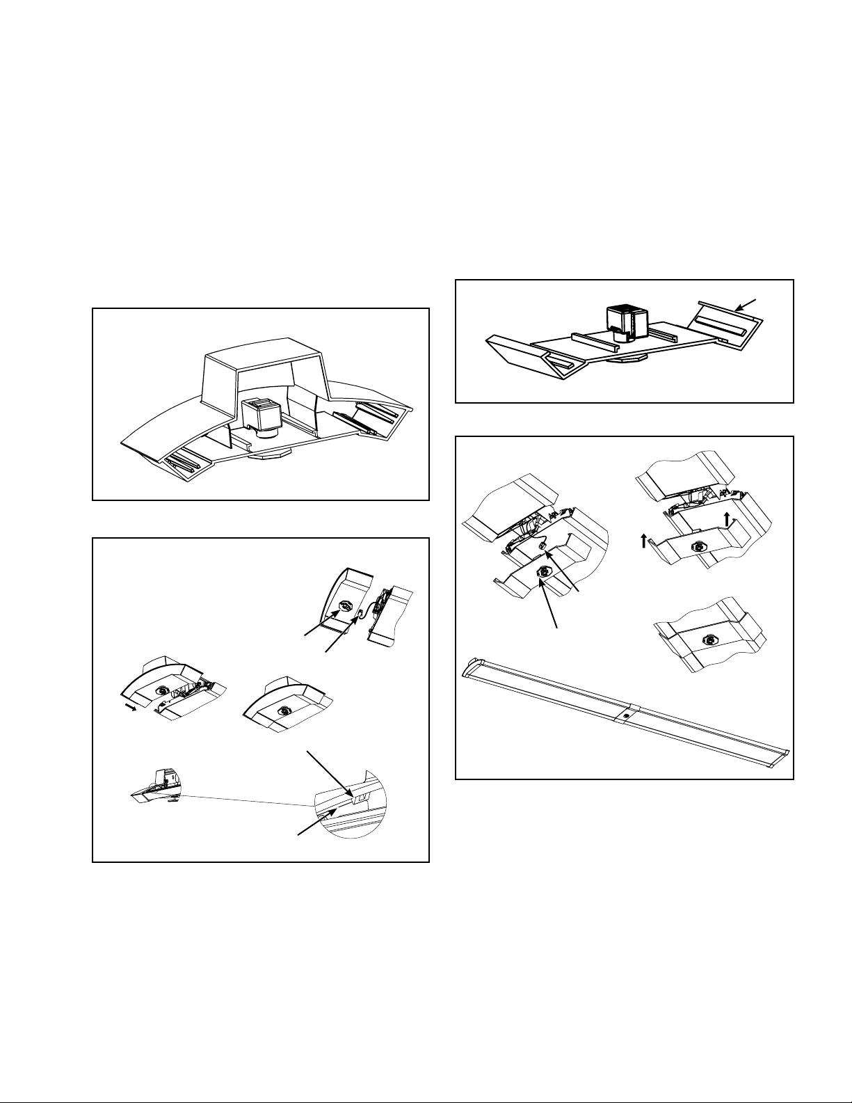
Emergency Installation – end of row
Emergency Installation – middle of row
Battery Backup Option Section
The endcap includes the test switch preassembled.
Connect the harness on the end of the fixture to the test
switch. Snap endcap in place per the standard installation
instructions. Tuck wire harnesses and safety cable while
installing. Endcap tabs must fully engage in the metal
bracket. (Figure 31.)
Test according to the instructions in the battery pack.
Figure 30. Test switch Preassembled
Battery Backup Option Section
The Rowtrim includes the test switch preassembled.
Connect the harness on the end of the fixture to the
test switch. Tuck wire harnesses and safety cable while
installing. Snap Rowtrim in place. (Figure 33.)
Test according to the instructions in the battery pack.
Rowtrim
Figure 32.
Test switch Preassembled
Figure 31.
Location for Test switch
Endcap Tab
Sheet metal Bracket in
Waveguide
Fixture harness
Fixture harness
Location for
Test switch
Figure 33.
7
COOPER LIGHTING SOLUTIONS IB519017EN Installation instruction
Installation Instruc tions – WaveStream Linear
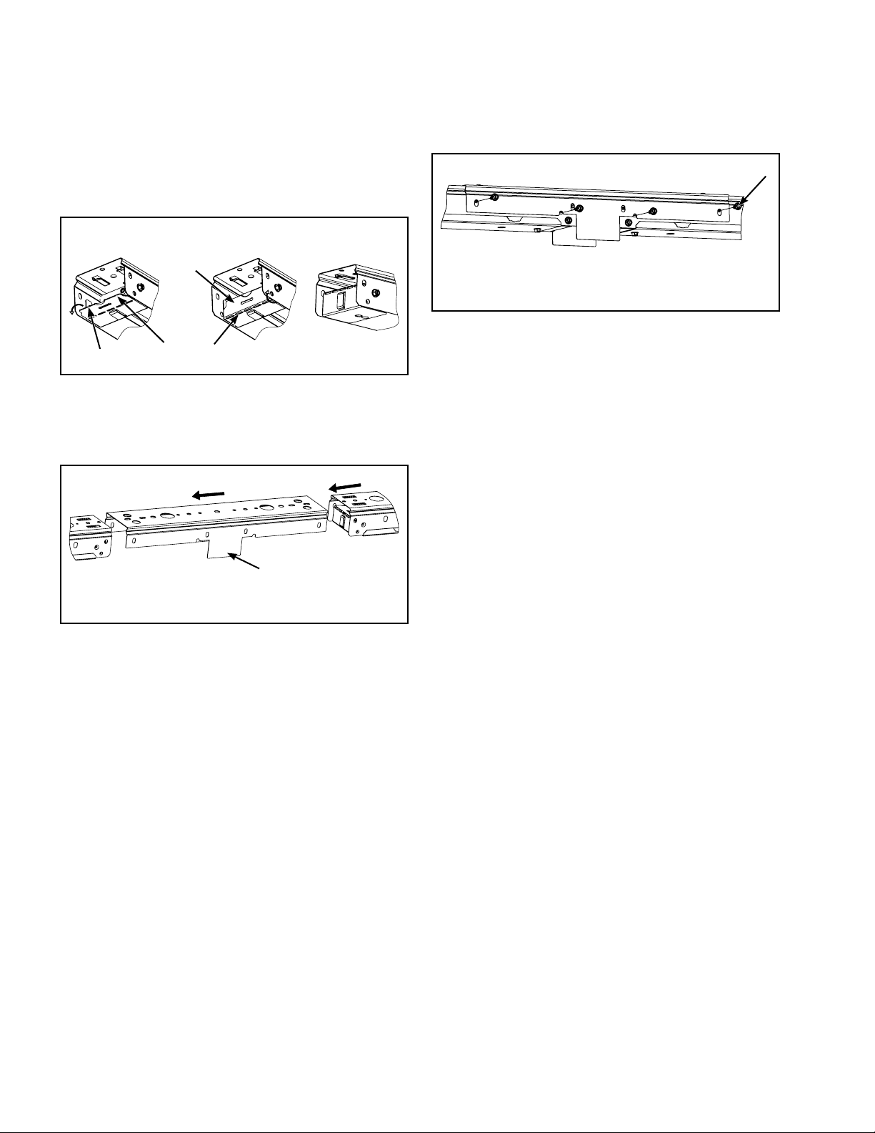
Sensor Option Installation: (Row Mount only) Section
(Step 1-5)
1. Rotate upper endplate, bend flange as shown and
rotate back to its original position in the Channel
assembly. (Figure 34.)
Flange
Flange
Figure 34.
2. Insert Channel Joiner to one of the channels and insert
another channel to the other end of Channel Joiner. This
creates a gap between fixture to install sensor.
Endplate
3. Install screws to secure Channel Joiner.
Screws
Figure 36.
4. To install waveguide assemblies repeat the steps 4 to 9
from Row Mount Installation.
5. The Rowtrim includes the sensor preassembled.
Connect the RJ11 cable coming from the end of the
fixture to the pigtail in the sensor. Snap Rowtrim in
place. Assure all wiring is covered in the Rowtrim.
Figure 35.
Channel Joiner
8
COOPER LIGHTING SOLUTIONS IB519017EN Installation instructions
Installation Instruc tions – WaveStream Linear
Occupancy/Daylight Harvesting Sensor
Installation – end of row
Occupancy/Daylight Harvesting Sensor
Installation – middle of row
Sensor Option Installation Section
The endcap includes the sensor preassembled. Connect
the RJ11 cable coming from the end of the fixture to the
pigtail in the sensor. Snap endcap in place per the standard
installation instructions. Tuck wire harnesses and safety
cable while installing. Endcap tabs must fully engage in the
metal bracket. (Figure 38.)
Figure 37. Sensor Preassembled
Pigtail
Sensor Option Installation: (Row Mount only) Section
(Step 1-5)
1. Rotate upper endplate, bend flange as shown and
rotate back to its original position in the Channel
assembly. (Figure 39.)
Flange
Flange
Figure 39.
2. Insert Channel Joiner to one of the channels and insert
another channel to the other end of Channel Joiner. This
creates a gap between fixture to install sensor.
Endplate
Figure 38.
Channel Joiner
RJ11
Figure 40.
3. Install screws to secure Channel Joiner.
Screws
Endcap Tab
Sheet metal Bracket in
Waveguide
Figure 41.
9
COOPER LIGHTING SOLUTIONS IB519017EN Installation instruction
Installation Instruc tions – WaveStream Linear
4. To install waveguide assemblies repeat the steps 4 to 9
from Row Mount Installation.
5. The Rowtrim includes the sensor preassembled.
Connect the RJ11 cable coming from the end of the
fixture to the pigtail in the sensor. Snap Rowtrim in
place. Assure all wiring is covered in the Rowtrim.
Figure 42.
Figure 43.
Rowtrim
Sensor Preassembled
Pigtail
RJ11
10
 Loading...