

Page 1

WLANPlus
Evaluation Kit User
Guide
MODEL: MtW_RGPlus_5.0_VB_001
Revision 2.3.5
Page 2

WLANPlus - Evaluation Kit User Guide
Uncontrolled copy. The user is responsible for verifying that the revision of this
document is the latest available, either by verifying on the company LAN or by
contacting the appropriate Metalink contact person.
This document contains data that is confidential and proprietary to Metalink Ltd.
Recipients of this document shall not make any use of the information contained
herein, except for the specific purpose for which it was received; conveying to any
third party, duplicating, copying by any method, part or the whole of this
document, without the prior written approval of Metalink, is prohibited.
If you are not the intended addressee, you are hereby notified that any
dissemination, distribution or copying of this data and any attachments thereto is
strictly prohibited. If you have received this document in error, kindly delete it from
your computer system or if received in hard format, kindly send it back to Metalink
via mail and notify us at the telephone number or email address below.
© 2008 Metalink Ltd. All rights reserved.
Metalink and WLANPlus are trademarks of Metalink Ltd. All other company
names, product or component names are the property of their respective
companies.
Patents pending. No patent rights or licenses to any of the devices or products
described herein are implied or granted to any third party.
THIS MATERIAL IS PROVIDED AS IS AND WITHOUT ANY EXPRESS OR IMPLIED
WARRANTIES, INCLUDING MERCHANTABILITY, FITNESS FOR A PARTICULAR
PURPOSE AND NON- INFRINGEMENT.
Metalink Ltd. reserves the right to make changes without further notice to any
device and product herein to improve reliability, function or design. Metalink Ltd.
assumes no responsibility for the use of this information or use of any device,
product, or component described herein.
Metalink's total liability in damages or otherwise shall not exceed the payment, if
any, received by Metalink for the product or service furnished or to be furnished, as
the case may be, resulting in the loss or damage claimed. In no event shall
Metalink be liable for any indirect, incidental, special, punitive, or consequential
damages as a result of its use
Metalink Ltd. products are not authorized for use as components in life support
devices or systems intended for surgical implant into the body or intended to
support or sustain life. The buyer agrees to notify Metalink Ltd. of any such
intended end use whereupon Metalink Ltd. shall determine availability and
suitability of its product or products for the use intended.
Contact Information:
Metalink Ltd., Yakum Business Park, 60972, Israel
Phone: +972-9-960-5000
Email: [email protected]
Worldwide Technical Support: http://www.mtlk.com
Revision 2.3.5 Page 2 of 69
Page 3

WLANPlus - Evaluation Kit User Guide
Contents
Federal Communication Commission Interference Statement 5
Acronyms and Glossary Terms 6
Revision History 8
1. Introduction to the WLANPlus Evaluation Kit 9
1.1 General Overview 9
1.2 Package Contents 10
2. Physical Description 12
2.1 Overview 12
2.2 MTW_RGPLUS_5.0_VB_001 Video Bridge 12
2.3 LED Indicators 14
2.4 CD-ROM 14
3. Getting Started 16
3.1 Overview 16
3.2 Setting Up the Evaluation Kit (AP/STA) 17
3.2.1 Connecting the Evaluation Kit to the Video
Streamer/Receiver 17
3.2.2 Assigning an IP Address 18
3.2.3 Powering Up the Evaluation Kit 21
3.2.4 Connecting STAs to the AP 21
4. Changing Configuration Settings 25
4.1 Accessing the WLANPlus Configuration Menu 25
4.2 General Settings 26
4.2.1 Wireless Settings 26
4.2.2 Network Interfaces 27
4.2.3 Configuring Route Mode 30
4.2.4 Status and Statistics 33
4.3 Advanced Settings 34
4.3.1 Advanced Wireless Settings 34
4.3.2 MAC filtering 35
Selecting MAC Filtering Type..................................................... 36
Editing the Access Control List................................................... 37
4.3.3 Security (AP Only) 37
Setting Open Security (no encryption)........................................ 38
Setting WEP Security................................................................. 39
Setting WPA/WPA2-Personal Security....................................... 40
Setting WPA/WPA2-Enterprise Security..................................... 41
4.3.4 Wi-Fi Protected Setup 43
Configuring WPS via PIN........................................................... 43
Configuring WPS via PBC.......................................................... 46
4.3.5 Access Control 47
4.4 Configuration and Profiles 48
4.4.1 Import/Export Configuration 48
4.4.2 Restore Defaults (AP) 49
4.4.3 Restore Defaults (Station) 50
4.4.4 Firmware Updates 51
4.4.5 Revert Changes 53
4.4.6 Verify and Apply Changes 53
Revision 2.3.5 Page 3 of 69
Page 4

WLANPlus - Evaluation Kit User Guide
5. Streaming Video over WLANPlus 54
5.1 Overview 54
5.2 Installing the VideoLAN Media Player 54
5.3 Streaming Video with VideoLAN Media Player 55
5.4 Receiving Video with VideoLAN Media Player 57
5.5 Setting VideoLAN Media Player for Multicast Mode 57
5.6 Installing NFS 58
A Appendix A: Default Settings for AP Profile 62
B Appendix B: Default Settings for STA(x) Profile
66
6. Index 69
Revision 2.3.5 Page 4 of 69
Page 5

WLANPlus - For product available in the USA/Canada market, only channel 1~11 can be operated. Selection of
other channels is not possible.
Federal Communication Commission
Interference Statement
This equipment has been tested and found to comply with the limits for a Class B
digital device, pursuant to Part 15 of the FCC Rules. These limits are designed to
provide reasonable protection against harmful interference in a residential
installation. This equipment generates, uses and can radiate radio frequency energy
and, if not installed and used in accordance with the instructions, may cause
harmful interference to radio communications. However, there is no guarantee that
interference will not occur in a particular installation. If this equipment does cause
harmful interference to radio or television reception, which can be determined by
turning the equipment off and on, the user is encouraged to try to correct the
interference by one of the following measures:
● Reorient or relocate the receiving antenna.
● Increase the separation between the equipment and receiver.
● Connect the equipment into an outlet on a circuit different from that to which the
receiver is connected.
● Consult the dealer or an experienced radio/TV technician for help.
FCC Caution: Any changes or modifications not expressly approved by the party
responsible for compliance could void the user’s authority to
operate this equipment.
This device complies with Part 15 of the FCC Rules. Operation is subject to the
following two conditions: (1) This device may not cause harmful interference, and
(2) this device must accept any interference received, including interference that
may cause undesired operation.
For product available in the USA/Canada market, only channel 1~11 can be
operated. Selection of other channels is not possible.
This device and its antenna(s) must not be co-located or operation in conjunction
with any other antenna or transmitter.
This device is going to be operated in 5.15~5.25GHz frequency range, it is
restricted in indoor environment only.
IMPORTANT NOTE:
FCC Radiation Exposure Statement:
This equipment complies with FCC radiation exposure limits set forth for an
uncontrolled environment. This equipment should be installed and operated with
minimum distance 20cm between the radiator & your body.
Revision 2.3.5 Page 5 of 69
Page 6

WLANPlus -
Acronyms and Glossary Terms
Acronyms and glossary terms that frequently appear in Metalink documentation
include:
Acronyms and Glossary Terms
Term Description
ACL Access Control List.
AP Access Point.
BPF Band Pass Filter.
BSS The Basic Service Set (BSS) is the basic building block of a
wireless LAN. Coverage of one access point is called a BSS. An
access point acts as a master to control the stations within that
BSS. Each BSS is identified by an SSID.
CB Channel Bonding.
CLI Command Line Interface.
ERP Extended Rate Policy.
ESSID Extended Service Set Identifier.
DUT Device Under Test.
IOCTLS Input/output controls - typically employed to allow userspace
code to communicate with hardware devices.
LDPC Low-Density Parity-Check code (LDPC code) - An error correcting
code. A method of transmitting a message over a noisy
transmission channel.
MIMO Multiple-Input and Multiple-Output - The use of multiple antennas
at both the transmitter and receiver to improve communication
performance. One of several forms of smart antenna technology.
mPCI Mini PCI - A bus standard for attaching peripherals to a
motherboard. Adapted from the Peripheral Component
Interconnect (PCI) bus. Originally designed for laptops and other
small-footprint computer systems.
nCB Non-Channel Bonding.
Multicast The delivery of information to a group of destinations
simultaneously using the most efficient strategy to deliver the
messages over each link of the network only once, creating
copies only when the links to the destinations split.
NFS Linux's "Network File System" - A way to share files between
machines on a network as if the files were located on the client's
local hard drive.
NWID Network Identification Designator.
OCS Optimal Channel Selection.
PBC Push Button Configuration.
RFIC RF Integrated Circuit.
Revision 2.3.5 Page 6 of 69
Page 7

WLANPlus -
Term Description
RSSI Received Signal Strength Indication - a measurement of the
power present in a received radio signal.
SISO Single Input Single Output.
STA Infrastructure Station.
UUID Universally Unique Identifier.
WEP Wired Equivalent Privacy - The original security protocol for Wi-Fi
networks.
WPA Wi-Fi Protected Access - A security protocol for Wi-Fi networks
which provides stronger security than WEP via enhanced
encryption and user authentication.
WPS Wi-Fi Protected Setup - A protocol designed to make it easier to
set up and configure security on Wi-Fi networks.
Revision 2.3.5 Page 7 of 69
Page 8

WLANPlus -
Revision History
Revision 2.3.5 includes updates for release of software v2.3.5
Added MAC filtering section (page 35)
Restore Defaults section expanded into two separate sections:
Restore Defaults (AP (page 49)
Restore Defaults (Station (page 50)
Added Firmware section (page 51)
Revision 2.3
Restructured document and made many minor fixes
Revision 2.2
Adaptation for release of v2.2
Revision 2.1
Updated for new software release
Revision 1.1
Dongle 2.0 updates
CLI screens Update
Wireless settings update
Revision 1.0
Initial release of this user guide
Revision 2.3.5 Page 8 of 69
Page 9

WLANPlus -
1. Introduction to the WLANPlus Evaluation Kit
In this chapter
General Overview ...................................................... 9
Package Contents .................................................... 10
1.1 General Overview
WLANPlus™ is an advanced wireless technology for distributing multimedia content
throughout the home. WLANPlus incorporates different techniques to obtain the
required breakthrough rate and reach while supporting the required QoS. Its
breakthrough performance is based on state-of-the-art MIMO technology, offering
increased throughput range and an enhanced ability to deal with interference, while
providing a rich and reliable user experience.
Main features:
Higher data transmission rates
Establishes a wireless connection in multi-path environments
Extended reach by delivering better SNR compared to legacy Single Input Single
Output (SISO) systems
Higher rates, extended range and improved spectral efficiency
Supports channels in the 5GHz-band
Advanced LDPC error-correction schemes, and sophisticated antenna loading
between channels
New aggregation schemes to improve MAC efficiency while supporting the latest
security and QoS standards
Comprehensive MIMO combinations, with up to 2 x 3
Uses 40MHz or 20MHz Spectrum mode (CB / non-CB)
AP and STA are WiFi certified:
802.11n
802.11d
Advanced security including the following configurable modes:
None (No security)
WEP – Open and shared key authentication
WPA personal
WPA enterprise (has not been tested)
WPA2 personal
WPA2 enterprise (has not been tested)
Configurable basic rate according to mode of operation
Revision 2.3.5 Page 9 of 69
Page 10

WLANPlus -
802.11a
802.11an
15-entry associated station list
PHY rate: up to 300Mbps; 140Mbps effective rate
Enhanced Rate-Adaptation algorithm
Full 802.11 Interoperability
Dynamic handling of mixed a/n networks
802.11n protection modes
Automatic STA scanning (searches for available APs)
Broadcast support
Multicast support (multicast-to-unicast conversion, to enable reliable multicast
support)
Bridge-mode support
Four-address bridge mode
Automatic reconnection and dead-station discovery
AP Forwarding
Automatic MAC cloning
Web-based configuration tool
802.11d
WPS ( Wi-Fi Protected setup )
Status and statistics.
OCS – Optimal channel selection mechanism.
The WLANPlus Evaluation Kit can be used to evaluate Metalink’s MtW8171 and
MtW8151, MIMO WLAN transceiver chipset. The WLANPlus Evaluation Kit allows
users with no special WLAN expertise to easily connect to testing equipment to
evaluate Metalink’s WLANPlus MIMO technology. The kit can be connected to
Consumer Electronic (CE) products to evaluate the development of embedded
WLAN capabilities or as an external add-on offering WLAN capabilities to existing
products.
Metalink provides an evaluation kit for:
WLANPlus Video Bridge (MTW_RGPLUS_5.0_VB_001) – 5GHz cable replacement
1.2 Package Contents
The Evaluation Kit package includes the following items:
WLANPlus Evaluation Kit
Power supply
Ethernet cable
Revision 2.3.5 Page 10 of 69
Page 11

WLANPlus -
CD-ROM
Revision 2.3.5 Page 11 of 69
Page 12

WLANPlus -
2. Physical Description
In this chapter
Overview ................................................................ 12
MTW_RGPLUS_5.0_VB_001 Video Bridge .................... 12
LED Indicators ......................................................... 14
CD-ROM ................................................................. 14
2.1 Overview
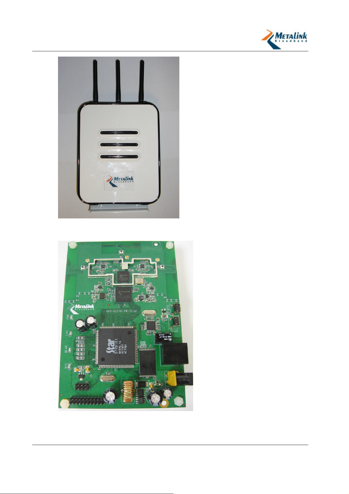
The WLANPlus Evaluation Kit consists of a plastic shell housing which includes the
following components:
Metalink board:
MTW_RGPLUS_5.0_VB_001 Video Bridge (VB)
Three antennas
12V DC power supply connector
2.2 MTW_RGPLUS_5.0_VB_001 Video Bridge
The MTW_RGPLUS_5.0_VB_001 Video Bridge Evaluation Kit contains the Metalink
WLANPlus MIMO chipset, which consists of the MtW8171 MAC/Baseband, and the
MtW8151 RFIC. The board supports 2 x 3 MIMO configurations.
The PCI interface of the wireless module is connected to a STAR 9101 Network
processor. The kit includes a single Ethernet interface for network connection.
The board includes:
Metalink’s chipset
STAR 9101 network processor
10/100 Mbps Ethernet connector
8 Mb Flash
32 Mb SDRAM
LED indicators
Revision 2.3.5 Page 12 of 69
Page 13
WLANPlus -
Figure 2-1- MTW_RGPLUS_5.0_VB_001 Video Bridge housing
Figure 2-2 - MTW_RGPLUS_5.0_VB_001 Video Bridge board
Revision 2.3.5 Page 13 of 69
Page 14

WLANPlus -
2.3 LED Indicators
The front panel includes four LED indicators
Name Function
PWR
WLAN
Ethernet
WPS
On: Host board completed its power-on cycle and init sequence
Off: Video Bridge is off or has not finished booting
On: Wireless LAN connection established.
Blinking – Traffic is transferred
Off: No connection
Blinking: Ethernet link is live. For GPB 244/236, there is a
separate Ethernet LED for each port
Off: Ethernet link not live
On: WPS push button is pushed
Off: WPS push button is not being pushed
2.4 CD-ROM
The CD-ROM includes the following software:
Name Description Path
Easy IP Config
Tool
Ethereal A network sniffer tool. \Misc\Ethereal\ethereal-setup-
Iperf A tool to measure TCP and UDP
MPEG Analysis
Tool
NFS Server for
Windows
TFTP A File Transfer Protocol server
VideoLAN Media
Player
A tool which displays an icon in
the system tray, and allows
seamless switching of
predefined IP addresses.
bandwidth performance.
A tool to analyze a video file’s
properties.
A tool that runs a Linux Network
File System server over a
Windows machine.
for Windows.
A media player which allows
playback, as well as streaming,
of video files.
\Misc\Easy IP Config
Tool\winips.exe
0.10.13.exe
\Misc\Iperf\iperf.exe
\Misc\MPEG Analysis Tool\Elecard
StreamEye Tools
\nfsAxe\SETUP.EXE
\TFTP\tftpd32.exe
\VideoLAN\vlc-0.8.5-win32.exe
Revision 2.3.5 Page 14 of 69
Page 15

WLANPlus -
Name Description Path
Documentation WLANPlus Evaluation Kit User
Guide v2.3.1 Release notes
\Software Documents Ver
2.3\WLANPlus Evaluation Kit
UG.doc
\Software Documents Ver
2.3\WLANPlus Release Notes SW
2.3.1doc
\Software Documents Ver 2.3\SUG
API Host Driver Linux.doc
Revision 2.3.5 Page 15 of 69
Page 16

WLANPlus -
3. Getting Started
In this chapter
Overview ................................................................ 16
Setting Up the Evaluation Kit (AP/STA) ....................... 17
3.1 Overview
This chapter provides an overview of the possible topologies and step-by-step
hardware installation instructions.
The Evaluation Kit provides the ability to evaluate Metalink’s MtW8171 and
MtW8151 MIMO WLAN transceiver chipset. The chipset is packaged inside an
Evaluation Kit for a seamless evaluation. The kit is preconfigured to serve as either
an Infrastructure Station (STA) or as an Access Point (AP).
A typical installation consists of one AP, which is physically connected to a
PC/device serving as a Video Streamer on one end, and one or more STAs,
connected to PCs/devices serving as Video Receivers on the other end. The AP
Evaluation Kit transmits the video stream to the STAs using wireless
communication.
The connection between the Evaluation Kits and the Video Streamer/Receiver(s)
uses an Ethernet interface. The connection is supported for both Windows-based
and Linux-based Video Receivers and Video Streamers.
It is recommended to use the Evaluation Kits with their factory configurations.
These are clearly marked on a label which includes the following information:
AP <IP Address> - This Evaluation Kit is configured to serve as the Access Point
and its preconfigured IP address is marked.
STA <1/2/3> <IP Adress>- This Evaluation Kit is configured to serve as a
Station and its preconfigured IP address is marked.
To change the preconfigured settings, follow the instructions inChanging
Configuration Settings on page 25.
Revision 2.3.5 Page 16 of 69
Page 17

WLANPlus -
3.2 Setting Up the Evaluation Kit (AP/STA)
The installation process consists of:
1. Connecting the AP/STA Evaluation Kit to the Video
Streamer/Receiver PC
2. Assigning an IP address to the PC
3. Powering up the Evaluation Kit
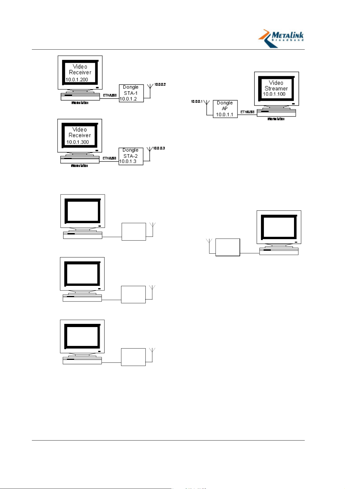
Figure 3-1 – Typical Topology
3.2.1 Connecting the Evaluation Kit to the Video Streamer/Receiver
1. Connect the Ethernet cable to the streamer/receiver PC’s Ethernet port.
2. Connect the other end of the Ethernet cable to the Evaluation Kit's Ethernet
port.
Revision 2.3.5 Page 17 of 69
Page 18
WLANPlus -
3.2.2 Assigning an IP Address
This chapter explains how to configure the IP address of the streamer/receiver PC
in order to communicate with the Evaluation Kit when the latter is configured to
operate in bridge mode.
The Evaluation Kit can be configured to operate in one of two connection modes,
Bridge Mode or Route Mode (not relevant for Evaluation Kits that are Video
Bridges). The Evaluation Kit’s default operating mode is Bridge Mode.
The Evaluation Kit’s LAN interface and the PC must be configured to the same
subnet.
To assign the IP address to the PC:
1. On the PC, from the Start menu, select Settings > Control Panel > Network
Connections.
The Network Connections screen displays your existing Network Connections.
2. Locate the Network Connection under Local Area Connection.
3. Right click the Local Area Connection and select Properties.
The Properties window appears.
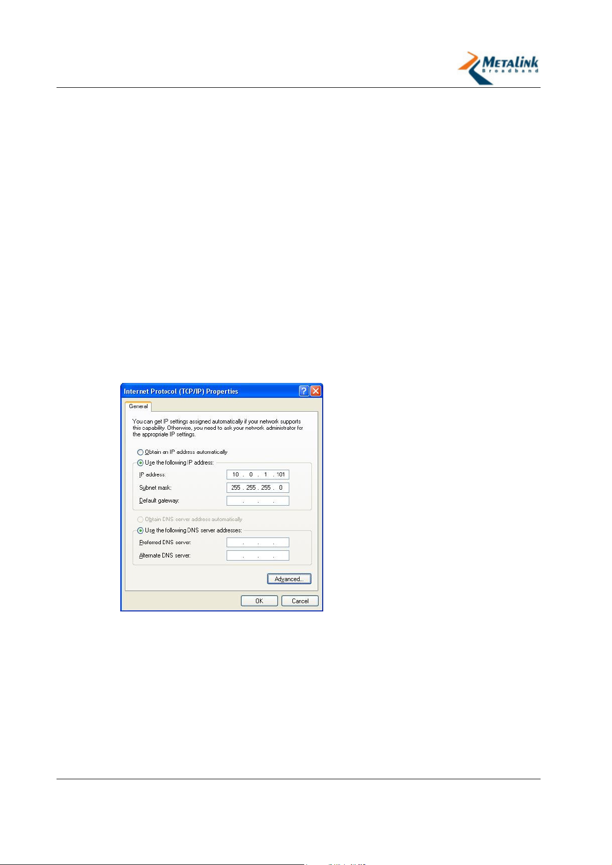
4. Select the Internet Protocol (TCP/IP), and then select Properties.
The Internet Protocol (TCP/IP) Properties window appears.
5. Select Use the following IP address, and then enter your IP address.
Revision 2.3.5 Page 18 of 69
Page 19
WLANPlus -
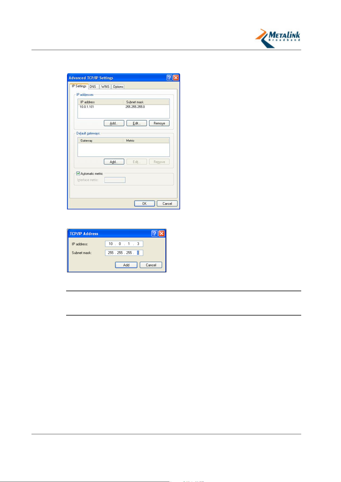
6. Select Advanced.
The Advanced TCP/IP Settings window appears.
7. In the IP Settings tab, select the IP address, and then select Add.
The TCP/IP Address window appears.
8. Enter the IP address (of the PC) that is on the same subnet as the Evaluation
Kit.
TIP:
For example, if the IP address of the Evaluation Kit (LAN Interface) is
“10.0.2.1”, the IP address of the corresponding PC should start with “10.0.2”
(e.g. 10.0.2.2).
9. In the Subnet Mask field, enter “255.255.255.0”.
10. Click Add.
The new Static IP Address is added.
11. Click OK.
Revision 2.3.5 Page 19 of 69
Page 20
WLANPlus -
Figure 3-2 - Typical IP Assignment in Bridge mode
Video
Receiver
10.0.2.2
Workstation
ETH/USB
Dongle
STA-1
10.0.2.1
10.0.0.2
10.0.0.1
Dongle
AP
10.0.1.1
ETH/USB
Video
Streamer
10.0.1.2
Workstation
Video
Receiver
10.0.3.2
10.0.0.3
Workstation
ETH/USB
Dongle
STA-2
10.0.3.1
Video
Receiver
10.0.4.2
10.0.0.4
Dongle
ETH/USB
Workstation
STA-3
10.0.4.1
Figure 3-3 – Typical IP Assignment in route mode
Revision 2.3.5 Page 20 of 69
Page 21
WLANPlus -
3.2.3 Powering Up the Evaluation Kit
To power up the Evaluation Kit:
1. Connect the power supply to the power connector.
2. Plug the power supply into an AC power source.
3. Wait 30 seconds.
The Power Supply LED flashes to indicate that the Evaluation Kit is ready.
3.2.4 Connecting STAs to the AP
The connection between the STA and the AP requires access to MetaLink’s
WLanPlus web-based management interface. Through the management interface,
the STA’s scan process for available AP's is initiated and the desired AP is selected
and connected to.
To connect an STA to the AP:
1. On the Receiver which is connected to the STA, open a web browser.
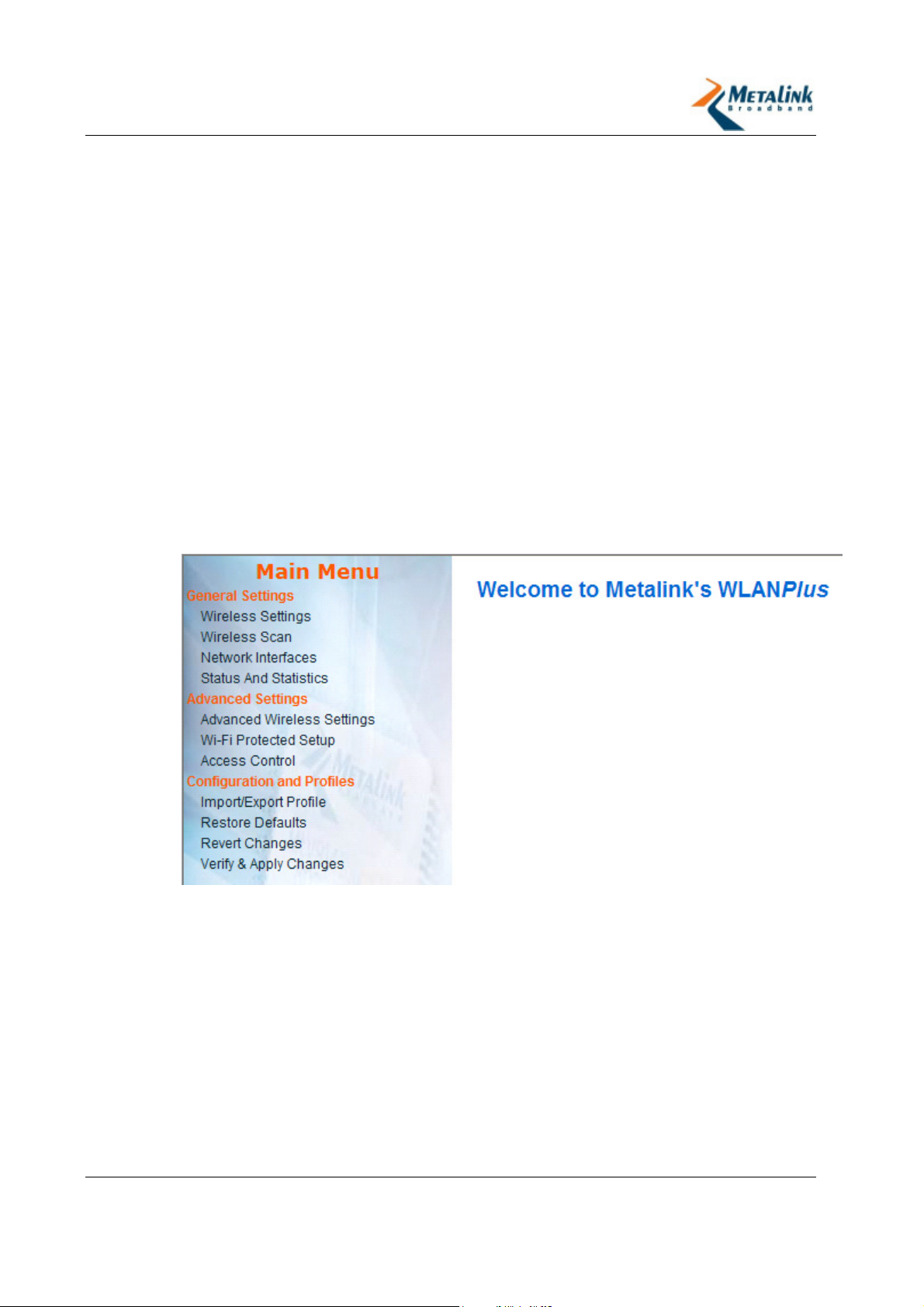
2. Navigate to the STA’s IP address. (e.g. http://10.0.1.2)
The Web Management Welcome page appears.
Revision 2.3.5 Page 21 of 69
Page 22
WLANPlus -
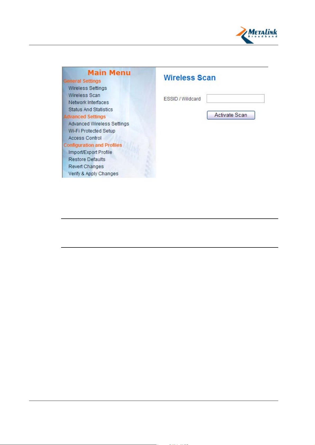
3. In the Main menu, select Wireless Scan.
The Wireless Scan page appears.
4. Click Scan to search for APs.
The results of the scan display the available APs with basic information about
the configuration and security settings of each.
5. Click the AP to which you wish to connect.
The Connection window appears.
TIP:
The fields in the Connection window depend on the security mode of the
AP. If the security of the AP that you have selected is set to Open/Unknown, the
STA requires no other configuration to connect to it. To connect to APs with any
other security setting (security enabled), follow the instructions below.
Revision 2.3.5 Page 22 of 69
Page 23
WLANPlus -
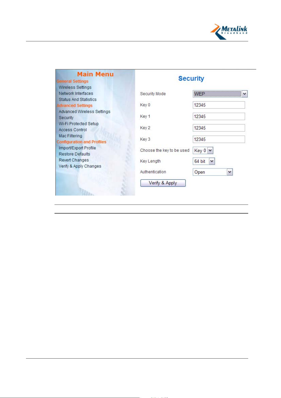
To connect a STA to a WEP- enabled AP:
1. Double click on the WEP-enabled AP.
The Security page appears.
2. Select the key to use from the Choose the key to be used field.
TIP:
This corresponds with the AP settings.
3. Enter the value of the key in the relevant key field. For example, if the value in
the Choose the key to be used field is “2”, enter the key into the Key 2 field.
4. In the Authentication field select the authentication method (WEP in the above
example) as selected in the AP.
5. Click Verify & Apply.
The Connect page appears, and displays the current connection status and the
BSSID Mac Address.
Revision 2.3.5 Page 23 of 69
Page 24
WLANPlus -
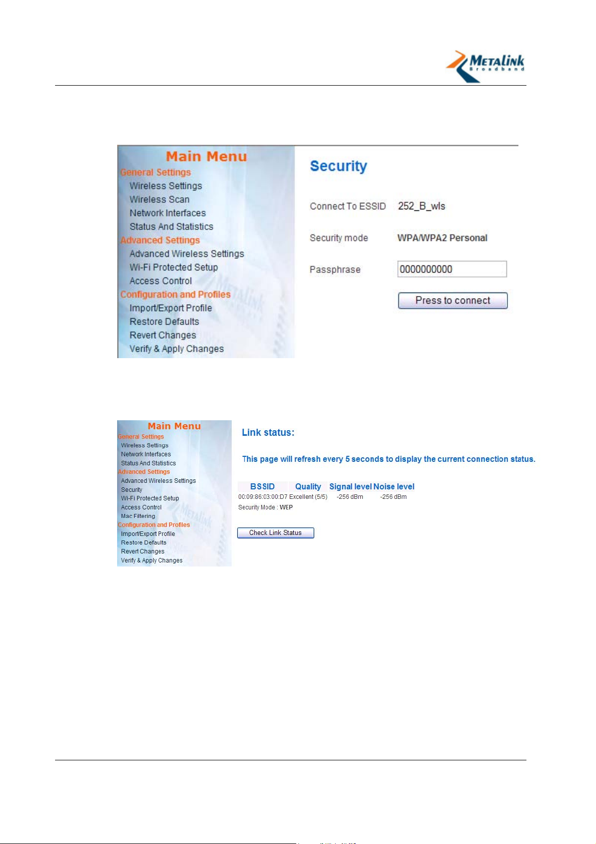
To connect an STA to a WPA/WPA2-enabled AP:
1. Double click on the WPA/WPA2-enabled AP.
The Security page appears.
2. In the Passphrase field enter the key that has been defined in the AP.
3. Click Press to Connect.
The Connect page appears, and displays the current connection status and the
BSSID Mac Address.
Revision 2.3.5 Page 24 of 69
Page 25
WLANPlus -
4. Changing Configuration Settings
The WLANPlus evaluation kit is shipped pre-configured and ready for use. However
it is possible to change the default settings using the supplied web-based
Configuration Management interface. The Configuration Management interface can
be accessed using any standard web-browser.
In this chapter
Accessing the WLANPlus Configuration Menu ............... 25
General Settings ...................................................... 26
Advanced Settings ................................................... 34
Configuration and Profiles ......................................... 48
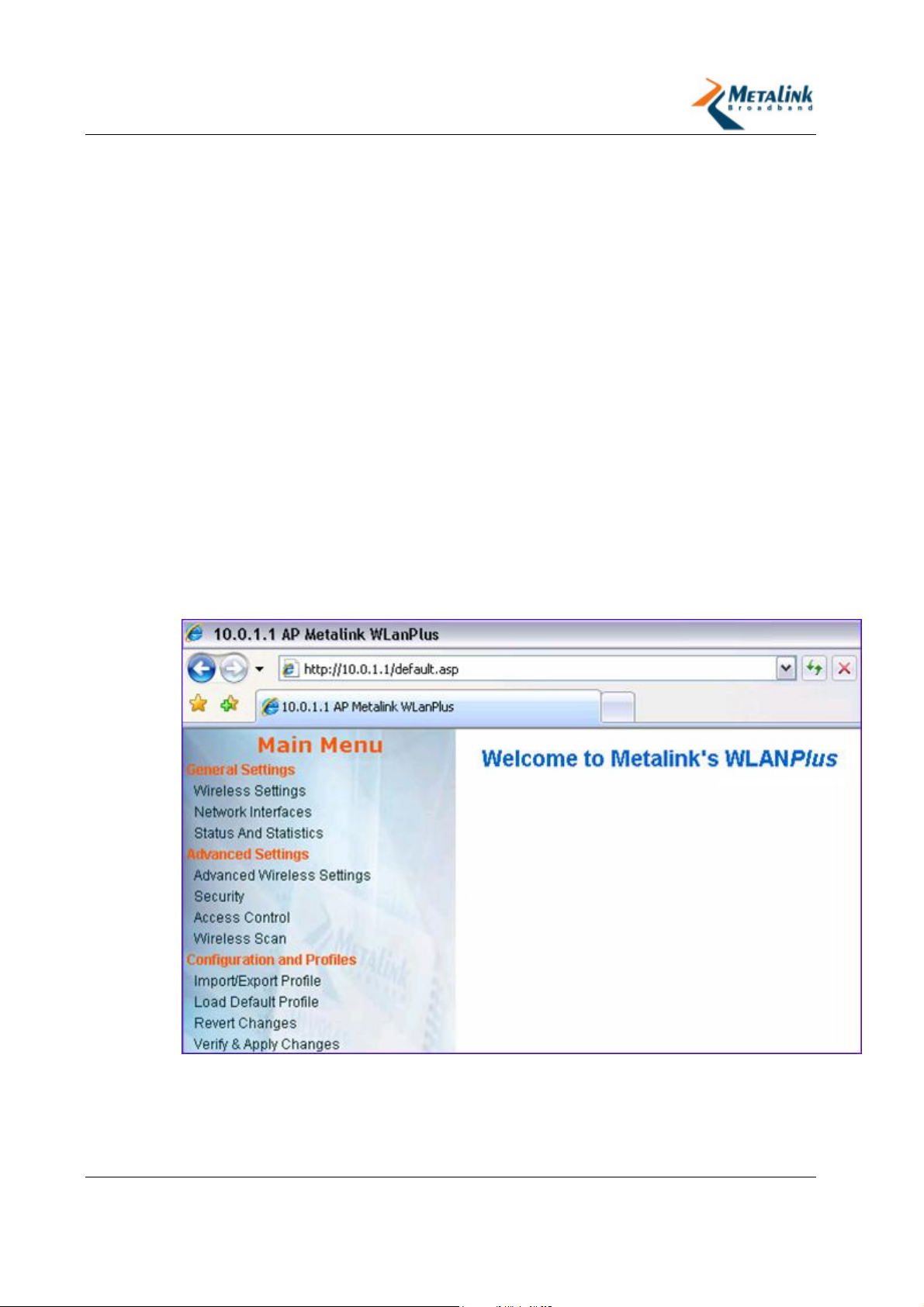
4.1 Accessing the WLANPlus Configuration Menu
To access the WLANPlus configuration pages:
1. Open a web browser and navigate to the following address:
http://<IP address of the dongle>
The main configuration page appears.
2. Select from the relevant area of the main menu as necessary:
General Settings (on page 26)
Advanced Settings (on page 34)
Configuration and Profiles (on page 48)
Revision 2.3.5 Page 25 of 69
Page 26

WLANPlus -
4.2 General Settings
4.2.1 Wireless Settings
The Wireless Configuration Settings include the wireless parameters for the
configuration of the wireless communication between an AP Evaluation Kit and the
STA Evaluation Kit(s).
WLANPlus complies fully with 802.11d standard.
The 802.11d standard allows a station to port between regulatory domains. The
STA performs passive scanning upon boot or BSS connection loss and upon
receiving a beacon from an AP, is updated with the regulatory domain restrictions
of the BSS. These restrictions include the maximum transmit power levels, allowed
channels, and class regulation parameters. The 802.11d functionality cannot be
disabled.
The following table describes the wireless settings:
Parameter Description Values
Device Type Specifies whether the device is an AP
or STA.
Frequency Band Specifies the operating band.
Note - Not all boards support both
bands
Channel (AP only) Specifies a specific channel for
operation. The list of available
channels is determined according to
the selections made in the band
parameters.
Specific Channel – in this mode the
user can select a specific channel
according to the device’s regulatory
domain..
Auto – in this mode the device uses
the Optimal Channel Selection
mechanism to select the best channel.
Channel Bonding
Usage (AP only)
Specifies whether channel bonding
should be enabled or disabled.
Access Point
Infrastructure
Station
5 GHz
Specific Channel
Auto
40 MHz – enables
channel bonding
20 MHz – disables
channel bonding
Secondary Channel
Offset (AP only)
ESSID (AP only) Configures the ESSID that the AP
Revision 2.3.5 Page 26 of 69
Specifies Upper or Lower sideband.
This setting is only relevant if the
Spectrum BW usage selected is
40MHz.
advertises within its network.
Upper
Lower
Entry is limited up
to 32
characters
Page 27
WLANPlus -
4.2.2 Network Interfaces
Each Evaluation Kit (STA and AP) includes LAN and WLAN interfaces. These
interfaces are configured separately. On Evaluation Kits with multiple LAN
interfaces, the LAN interfaces are bridged by default and have the same IP address.
Metalink’s Video Bridge Evaluation Kit operates only in Bridge mode (it is not
possible to configure it to operate in Route mode).
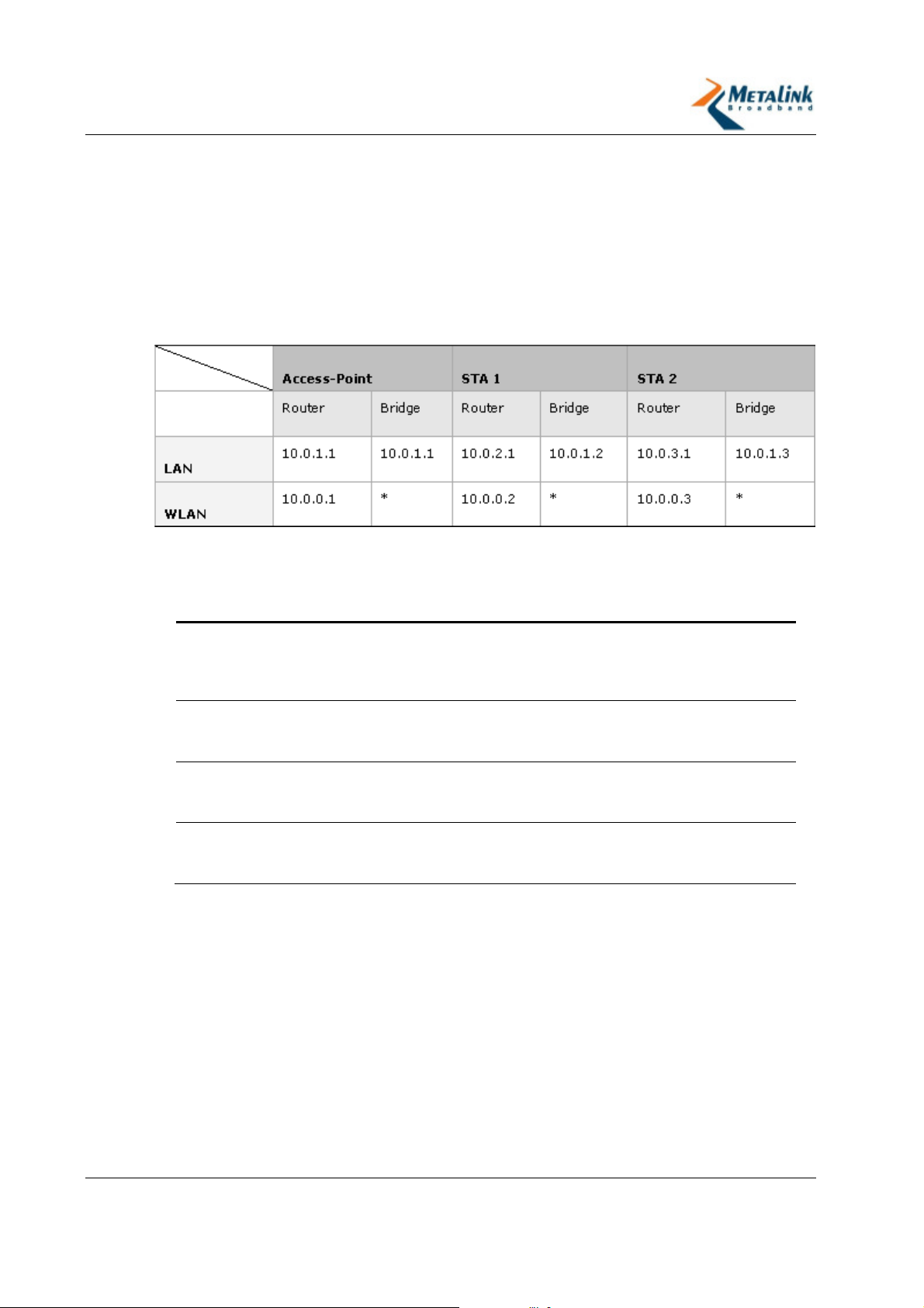
The following table summarizes the default network interface settings for the
various devices.
The following table describes the parameters that can be configured.
Parameter Description Values
IP Specifies the Ethernet LAN
IP address for both
Ethernet ports – LAN (0)
and LAN (1).
Subnet Specifies the Subnet-Mask
of the network, of the
specified IP address.
Ethernet MAC
Address
(port 0 – LAN)
Ethernet MAC
Address
(port 1 – WAN)
Specifies the MAC
addresses for the port 0LAN port.
Specifies the MAC
addresses for the port 1WAN port.
IP Address
Subnet
MAC Address
Revision 2.3.5 Page 27 of 69
Page 28

WLANPlus -
Parameter Description Values
Network Mode Specifies whether the
network will operate in
Bridge or Route modes.
There are several bridge
modes possible.
For AP:
Bridge (Default) – operation in
Bridge mode.
Four Address support - This
Bridge mode allow usage of 4
MAC address in the Wireless
packet.
Route – operation in Route
mode.
For STA:
L2-NAT (default) – When
operating in L2-NAT mode,
packets are sent from the AP to the
station in 3 MAC addresses in the
header. The station contains a
table with the IP’s and MAC
address of all the computers
connected to it and change the
MAC address of the Packets when
it is transferred to the Computer
behind the station.
Bridging MAC Cloning –
operation in Bridge mode,
where the STA uses the host’s
IP address. With MAC Cloning,
an AP will not be able to
access the target STA through
its WLAN address, but will be
able to access the target host
connected to that STA’s LAN
port. This mode supports
operation with security.
Four Address Support –
operation in Bridge mode,
where the AP can access the
target STA through its WLAN
address. This mode allows the
use of security and for several
host PCs to be connected
behind the STA. Four Address
Support is Metalink’s
proprietary implementation of
the Wireless Distribution
System (WDS) capability and
will not be supported by other
vendors.
Route – operation in Route
mode.
Revision 2.3.5 Page 28 of 69
Page 29

WLANPlus -
Parameter Description Values
Wireless LAN Mac
Address
Wireless LAN IP
(Route Mode only)
Cloned MAC
Address
(Bridge mode for
STA only)
Wireless LAN
Subnet
Displays the MAC address
of the wireless interface
(cannot be changed).
Specifies the IP address of
the wireless LAN. This IP
address is mandatory
when setting the network
in Route mode.
Relevant only in
Evaluation Kits that are
not Video Bridge
Displays the Clone MAC
address of the Host
(connected to the
Evaluation Kit)
Specifies the Subnet
address of the Wireless
LAN. This Subnet address
is mandatory when setting
the network in Route
mode. Enter the following
Subnet address:
255.255.255.0
e.g. 00:09:86:BA:F0:81
e.g. 00:09:86:BA:F0:81
Setting the cloned MAC
Address to 00:00:00:00:00:00
will trigger an automatic
adjustment to the STAs MAC
address according to the MAC
address of the connected
device/PC. The automatic
adjustment will be done after
a system reboot.
Revision 2.3.5 Page 29 of 69
Page 30
WLANPlus -
4.2.3 Configuring Route Mode
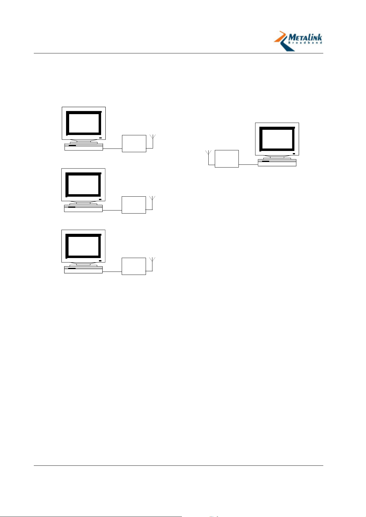
The default configuration of WLANPlus is Bridge mode, however you may choose to
setup the wireless network to operate in Route mode (on Evaluation Kits that are
not Video Bridge). The following diagram illustrates a typical wireless network setup
in Route mode.
Video
Receiver
10.0.2.2
Workstation
Video
Receiver
10.0.3.2
Workstation
ETH/USB
ETH/USB
Dongle
STA-1
10.0.2.1
Dongle
STA-2
10.0.3.1
10.0.0.2
10.0.0.1
10.0.0.3
Dongle
AP
10.0.1.1
ETH/USB
Video
Streamer
10.0.1.2
Workstation
Video
Receiver
10.0.4.2
10.0.0.4
STA-3
Workstation
ETH/USB
Dongle
10.0.4.1
To configure Route mode:
1. In the Network Interfaces screen, in the IP field, enter the Ethernet LAN IP
address.
2. In the Subnet field enter 255.255.255.0.
3. In the Ethernet MAC Address (port 0 – LAN) and (port 1 – WAN), enter
the MAC address of the Ethernet ports (port 0-LAN and port 1-WAN).
4. In the Enable Bridge Mode field, set to No.
5. In the Wireless LAN field, enter the IP address of the wireless LAN (e.g. in the
above topology when configuring STA-1 the Wireless LAN IP address is:
10.0.0.2).
6. In the Wireless LAN Subnet field, enter the Subnet-Mask of the wireless
interface (e.g. 255.255.255.0).
Revision 2.3.5 Page 30 of 69
Page 31
WLANPlus -
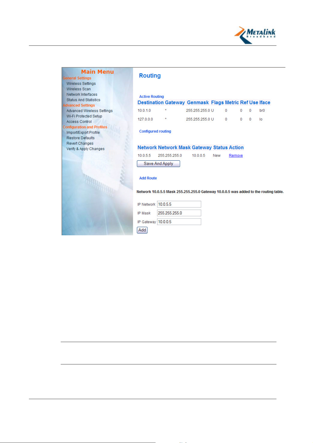
7. Click Configure Routing.
The Routing page appears.
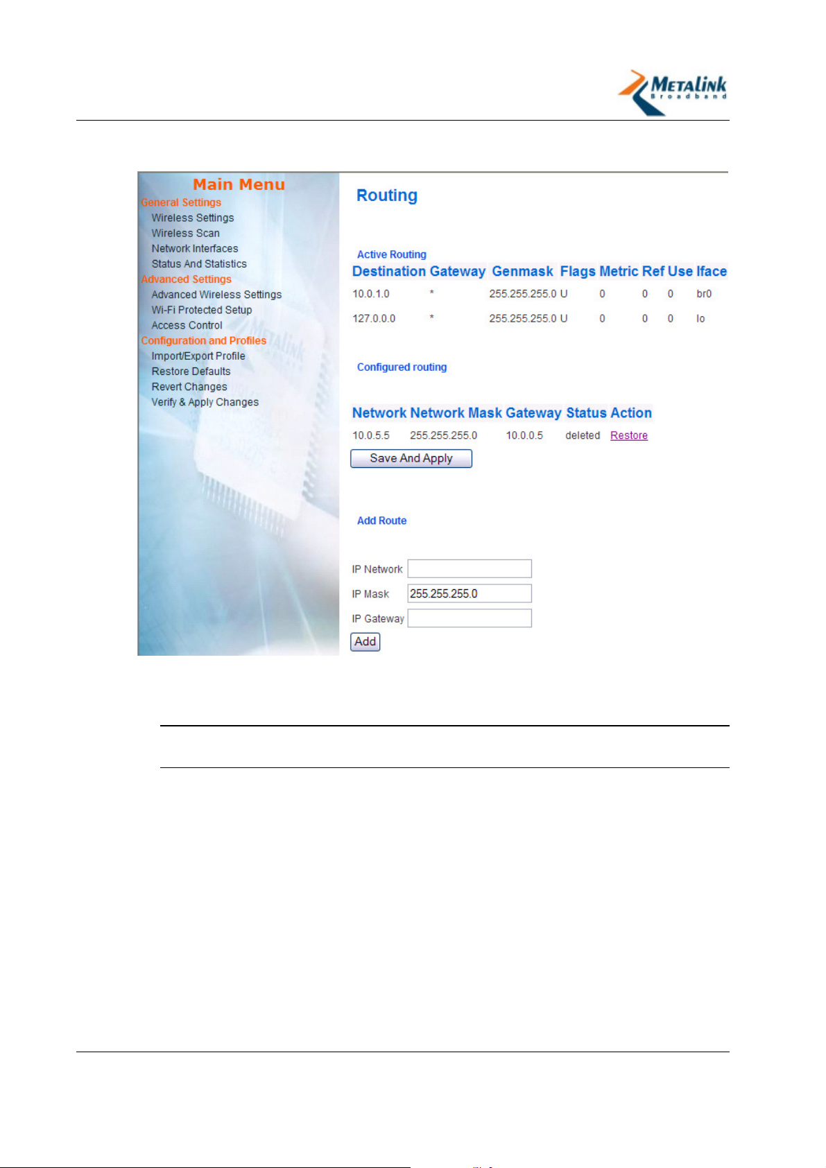
8. At the bottom of the page, enter the IP address of the destination into the IP
Network field. (e.g. in the above topology when configuring STA-1 the
destination is the IP address of the AP: 10.0.1.1 or 10.0.1.0)
9. In the IP Mask field, enter 255.255.255.0.
10. In the IP Gateway field, enter the IP address of the destination’s IP Gateway.
(e.g. in the above topology when configuring STA-1 the destination is the IP
address of the gateway, which is the wireless LAN address of the destination:
10.0.0.1).
11. Click Add.
The new route is added to the Configured Routing section at the top of the
page and its status appears as New. At this stage the route is not activated.
12. To activate the route, click Save and Apply.
The route appears in the Active Routing section at the top of the page and its
status is shown as Active.
TIP:
When configuring the AP to operate in Route mode repeat steps 8-11 for
each STA that will be connected to the AP and then follow step 12 to activate
them.
Revision 2.3.5 Page 31 of 69
Page 32
WLANPlus -
To remove route:
1. Click Remove.
Status of the “route” changes from Active to Deleted.
2. Click Save and Apply for remove.
TIP:
You do not need to reboot the Evaluation Kit for the routing configuration
to take effect.
Revision 2.3.5 Page 32 of 69
Page 33

WLANPlus -
4.2.4 Status and Statistics
Parameter Description
Display Version
Information
Show Link Status
Show Statistics
The following information appears when you click Version Info:
Information about the Evaluation Kit’s current firmware
version, the Linux OS version, and a combined version
number. The combined version number represents a certain
combination of firmware and Linux versions.
A list of modules which are installed on the Evaluation Kit, their
version numbers and their status in terms of the CRC check
(OK/CRC check failed). If a certain CRC check fails, a warning
message appears at the bottom with the cause of failure.
The following information appears when you click Link Status:
For AP:
The number of STAs that are connected to it.
The BSSID to which it is connected, represented by the MAC
Address of the AP.
If there are no STAs connected, the No STA Connected
message appears.
For STA:
The SSID to which the STA is connected.
The BSSID to which the STA is connected (represented by the
MAC address of the AP to which it is connected).
The following information appears when you click Statistics:
ifconfig Statistics: displays the results that are obtained by
using the “ifconfig” command in the Evaluation Kit’s Linux
console (similar to the “ipconfig” command in Windows). All
the network interfaces of the Evaluation Kit are presented
including their IP addresses, subnet masks and overall TX and
RX statistics.
TC Output (packets lost in OS): displays the packet traffic
through the various interfaces of the device. The WLAN
interface (wlan0) is further divided into four separated
priorities, corresponding to the different QoS queues. The
“dropped” counter indicates the number of packets that were
rejected by the OS.
MAC Statistics: Displays packet traffic running through the
MAC.
Additional Statistics: Displays miscellaneous statistics such as
Aggregated packets, 802.11 management and control frames
and various RX and TX traffic per priority queue.
MAC Events and
Exceptions
The following information appears when you click MAC Events
and Exception:
Displays the events in the wireless interface, and/or the
configured exceptions outputted by the Evaluation Kit.
Revision 2.3.5 Page 33 of 69
Page 34

WLANPlus -
4.3 Advanced Settings
4.3.1 Advanced Wireless Settings
Parameter Description Values
Use LDPC Low-Density Parity-check Code. It
enables/disables error correction for
reducing the probability of data loss in
noisy channels. The Rate Adaptation
algorithm automatically disables LDPC
coding when working at high PHY
rates (higher than 162).
ERP Protection Type This feature allows protection of OFDM
packets despite the presence of
802.11b stations within the BSS. By
sending RTS/CTS or CTS2Self packets
in 802.11b rates, the device informs
the BSS that OFDM packets are going
to be transferred and protects the
packets in the BSS. The RTS/CTS and
CTS2Self creates overhead which may
result in lower throughputs.
The RTS/CTS option provides better
coverage compared to CTS-to-Self,
but results in lower throughputs. This
is caused by the fact that the
RTS/CTS option includes
acknowledgement from the receiving
device, while the CTS2Self option
does not.
Use Overlapping
BSS protection (AP
only)
This option enforces BSS protection
when the AP detects beacons from
overlapping 802.11b APs or
overlapping APs with the ERP bit
turned-on. In this case when the AP
will detect a beacon from an
overlapping BSS it will extend the
protection coverage to its BSS.
Yes - Uses LDPC
advanced errorcorrection scheme
No - Uses the
Vietrbi FEC
algorithm
RTS/CTS
None – may cause
collision between
OFDM and CCK
packets.
CTS2Self
Yes
No
Revision 2.3.5 Page 34 of 69
Page 35

WLANPlus -
Parameter Description Values
11n Protection Type This feature allows protection from
non-HT Stations within the BSS. In
case the AP detects an association of
a non-HT legacy STA, it will signal all
the HT STAs to use RTS/CTS or CTSto-Self mechanisms before each data
transmission. This feature also
supports all 802.11n standard
protections, including MIMO.
The RTS/CTS option provides better
coverage compared to CTS-to-Self,
but results in lower throughputs. This
is caused by the fact that the
RTS/CTS option includes
acknowledgement from the receiving
device, while the CTS2Self option
does not.
Enable AP
forwarding (AP
only)
Use reliable
multicast (AP only)
Hidden SSID This feature provides very basic
Enables the ability of the AP to relay
packets from STA to STA within the
BSS
This feature enables the transmission
of multicast traffic through separate
unicast streams to enable
acknowledgments by each recipient.
This mechanism ensures that the
unreliable multicast data will arrive at
its destination.
security (mostly for home usage)
without the need to configure
additional security settings.
When chosen, the AP does not
advertise the SSID of it’s BSS in the
transmitted beacons. In this way, the
BSS will not be seen in the scan
results of wireless stations and hence
only stations with prior knowledge of
the SSID will be able to establish a
connection.
RTS/CTS
None - may cause
collision between
HT and legacy
packets
CTS2Self
Yes
No
Yes
No
Yes
No
Percentage of
maximal transmit
power
Sets the percentage of maximal
transmit power relative to the
regulatory domain restrictions. For
example, if the regulatory domain
restriction allows transmission of up to
20db, setting the percentage at 50%
will allow maximal transmit power of
10db.
4.3.2 MAC filtering
I
MPORTANT:
Revision 2.3.5 Page 35 of 69
The MAC filtering options are only relevant for AP mode.
12%
25%
50%
100%
Page 36
WLANPlus -
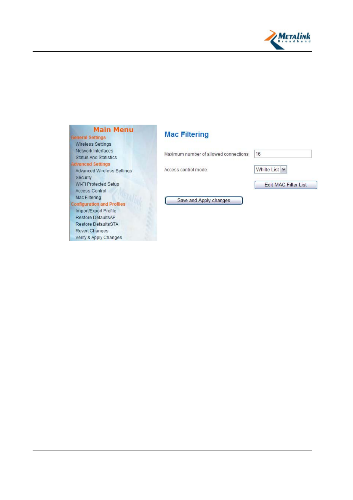
This feature controls the authentication process of STAs to the AP. Each STA is
checked against the Access Control List. The maximum number of STAs that can
associate with an AP is 16.
Selecting MAC Filtering Type
1. From the Main Menu, click Mac Filtering.
The Mac Filtering page appears.
2. From the Access Control Mode dropdown list, select from the following modes:
Open - The MAC will not check the ACL. The only limit for the association of
STAs is the supported number of stations.
White list - Allow only stations in the ACL to connect. Reject all other
stations.
Black list - Reject all stations in the ACL to connect. Allow all other stations
to connect.
Revision 2.3.5 Page 36 of 69
Page 37
WLANPlus -
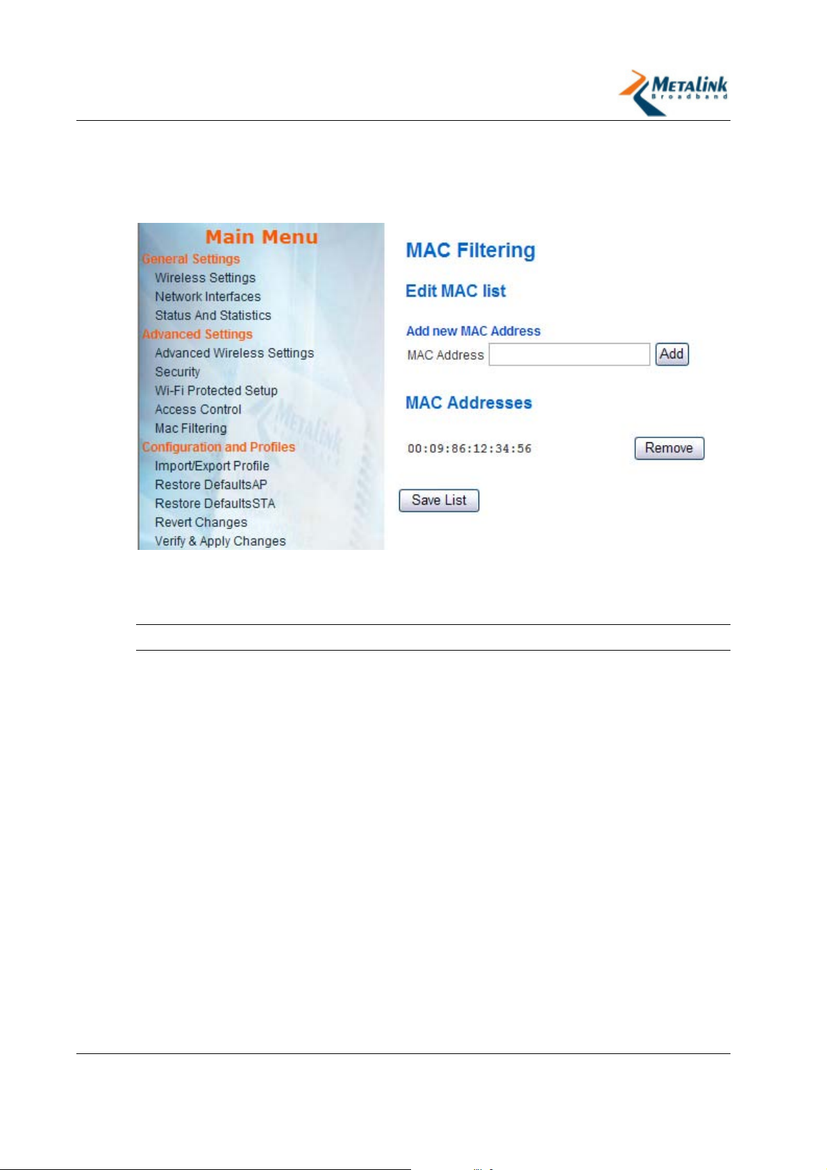
Editing the Access Control List
If you are using either the White or Black List mode, you should edit the Access
Control List to add or remove MAC addresses as necessary.
4.3.3 Security (AP Only)
I
MPORTANT:
WLANPlus features support for the following security protocols: WEP, WPA/WPA2
Personal, and WPA/WPA2 Enterprise. The security settings are defined in the AP. To
configure the settings for any of these protocols, see the appropriate section:
Setting WEP Security (on page 39)
Setting WPA/WPA2-Personal Security (on page 40)
Setting WPA/WPA2-Enterprise Security (on page 41)
Optionally, you can set Open Security (no encryption) (see "Setting Open Security
(no encryption)" on page 38).
The WLANPlus security options are only relevant for AP mode.
Revision 2.3.5 Page 37 of 69
Page 38
WLANPlus -
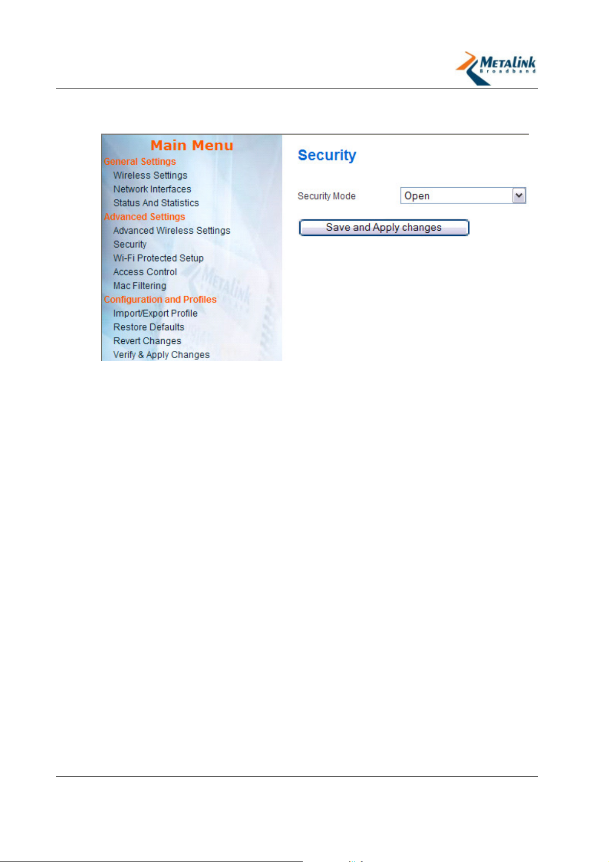
Setting Open Security (no encryption)
Figure 4-1 - AP Open Security Page
Setting to Open security disables the encryption of data between the AP and STAs.
To configure Open security:
1. In the AP’s Configuration Management interface go to Advanced Settings >
Security.
2. In the Security Type field, select Open.
3. Click Save and Apply Changes.
The BSS encryption is disabled.
Revision 2.3.5 Page 38 of 69
Page 39
WLANPlus -
Setting WEP Security
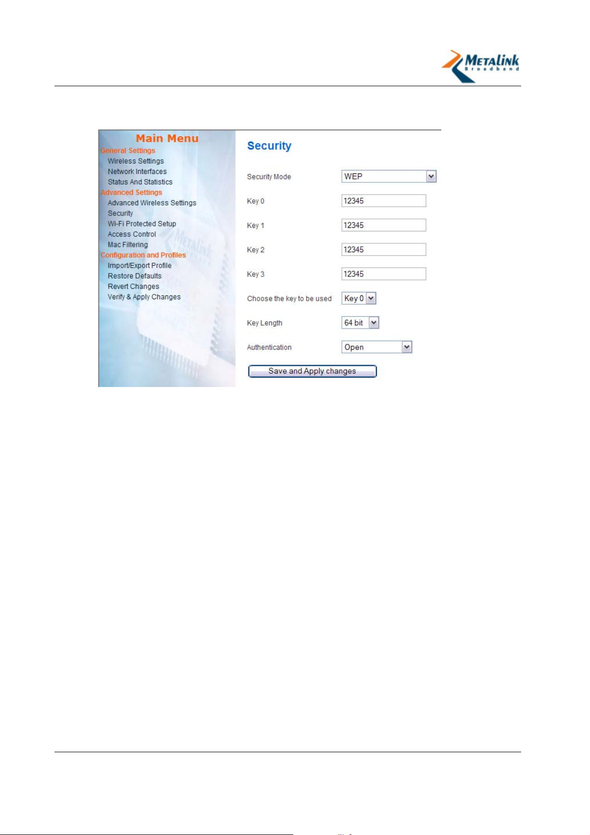
Figure 4-2 - AP WEP Security Page
The AP can be configured to provide WEP-based security encryption. Wired
Equivalent Privacy (WEP) is the weakest security mode and is not recommended.
To configure WEP security:
1. In the AP’s Configuration Management interface go to Advanced Settings >
Security.
2. In the Security Type field, select WEP.
3. In the Key Length field, select one of the following:
64 bit – enables 64-bit encryption. When selected the encryption key length
may be 10 hexadecimal characters or five alphanumeric characters.
128 bit – enables 128-bit encryption. When selected the encryption key
length may be 26 hexadecimal characters or 13 alphanumeric characters.
4. In the Choose the key to be used field, select the index of the key that will
used to encrypt/decrypt transmitted packets.
5. Enter the value of the key in the relevant key field. For example, if the value in
the Choose the key to be used field is “2”, enter the key into the Key 2 field.
6. In the Authentication field, determine if the WEP authentication process will be
performed prior to associating an STA to the BSS by selecting one of the
following:
Open - indicates that the station will not be authenticated by the AP.
Pre-shared Key – indicates that the AP will require the STA to perform the
authentication procedure using the same key that was defined above.
7. Click Save & Apply Changes.
Revision 2.3.5 Page 39 of 69
Page 40
WLANPlus -
Setting WPA/WPA2-Personal Security
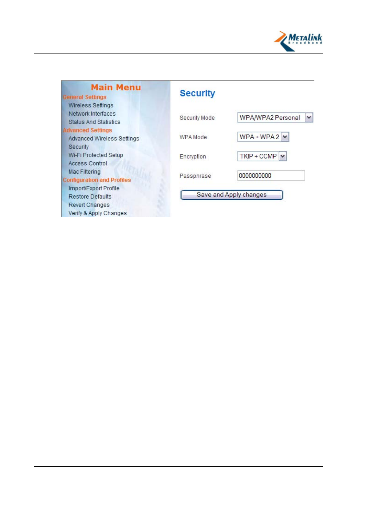
Figure 4-3 - AP WPA/WPA2 Personal Security Page
The AP can be configured to provide WPA/WPA2 Personal security encryption. WiFi
Protected Access (WPA) is the newest and most secure standard in Wi-Fi. WPA2 is the
newer version of WPA but with stronger encryption. WPA and WPA2 offer two
encryption methods: TKIP and CCMP. CCMP is stronger than TKIP. Further details
are below.
The WLAN Plus Evaluation Kit offers backwards compatibility to legacy devices that
do not support advanced security modes such as WPA2.
To configure WPA/WPA2 Personal security:
1. In the AP’s Configuration Management interface go to Advanced Settings >
Security.
2. In the Security Type field, select WPA/WPA2 Personal.
3. In the WPA Mode field, select one of the following:
WPA – WiFi Protected Access offers encryption and authentication
improvements that are stronger than the Wireless Encryption Protocol (WEP)
but weaker than the WPA2. Select this option if you would like to allow
access by non-WPA2 devices (legacy) only.
WPA2 – Newer version of WPA with stronger encryption.
WPA + WPA2 – This option provides access to both WPA and WPA2-
compatible devices.
4. In the Encryption field select one of the following:
TKIP - Temporal Key Integrity Protocol incorporates Message Integrity Code
(MIC) to provide protection against hackers. TKIP was designed as part of a
solution to replace WEP without replacing legacy hardware. Select this
option if you would like allow access by non-CCMP compatible devices
(legacy) only.
Revision 2.3.5 Page 40 of 69
Page 41
WLANPlus -
CCMP - Counter Mode with Cipher Block Chaining Message Authentication
Code Protocol is an IEEE 802.11i encryption protocol, created to replace,
together with TKIP, the earlier, insecure WEP protocol. CCMP uses the
Advanced Encryption Standard (AES) algorithm. In the CCMP, unlike TKIP,
key management and message integrity is handled by a single component
built around AES. Select this option to restrict access to CCMP-compatible
devices only (non-legacy).
TKIP + CCMP - This option provides access to both TKIP and CCMP
compatible devices.
5. In the Passphrase field enter a pass phrase of 8-63 characters.
6. Click Save and Apply Changes.
Setting WPA/WPA2-Enterprise Security
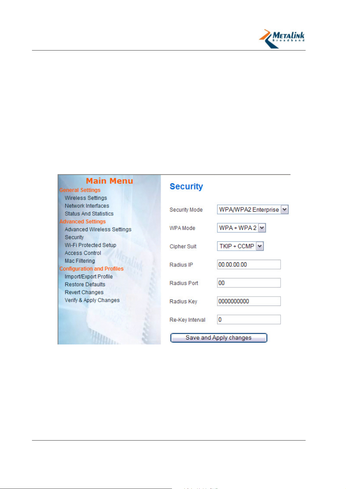
Figure 4-4 - AP WPA/WPA2 Enterprise Security Page
WPA/WPA2-Enterprise uses a RADIUS (Remote Authentication Dial-In User Service)
server for authentication. There are a few methods for performing the
authentication by the RADIUS server. One method is to have a certificate installed
at the STA-side (eap-tls). Other methods do not require this certification (eap-ttls,
and eap-peap).
Revision 2.3.5 Page 41 of 69
Page 42

WLANPlus -
To configure WPA/WPA2 Enterprise security:
1. In the AP’s Configuration Management interface go to Advanced Settings >
Security.
2. In the Security Type field, select WPA/WPA2 Enterprise.
3. In the WPA Mode field, select one of the following:
WPA – WiFi Protected Access offers encryption and authentication
improvements that are stronger than the Wireless Encryption Protocol (WEP)
but weaker than the WPA2. Select this option if you would like allow access
by non-WPA2 devices (legacy) only.
WPA2 – newer version of WPA with stronger encryption.
WPA + WPA2 – This option provides access to both WPA and WPA2-
compatible devices.
4. In the Cipher Suite field select one of the following:
TKIP - Temporal Key Integrity Protocol, incorporates Message Integrity
Code (MIC) to provide protection against hackers. TKIP was designed as part
of a solution to replace WEP but without replacing legacy hardware. Select
this option if you would like allow access by non-CCMP compatible devices
(legacy) only.
CCMP - Counter Mode with Cipher Block Chaining Message Authentication
Code Protocol is an IEEE 802.11i encryption protocol, created to replace,
together with TKIP, an earlier, insecure WEP protocol. CCMP uses the
Advanced Encryption Standard (AES) algorithm. In the CCMP, unlike TKIP,
key management and message integrity is handled by a single component
built around AES. Select this option to restrict access to CCMP-compatible
devices only (non-legacy).
TKIP + CCMP - This option provides access to both TKIP and CCMP
compatible devices.
5. In the Radius IP field, enter the IP address of the RADIUS server.
6. In the Radius Port field, enter the relevant port number in the RADIUS server.
7. In the Radius Key field, enter the encryption key used by the AP to access the
RADIUS server. The same key should be defined in the RADIUS server. The key
length should be up to 128 characters. This key is used to register the AP on the
RADIUS server and is then replaced by other keys.
8. In the Re-Key Interval field, enter the interval in seconds for the RADIUS
server to replace the key for security purposes.
9. Click Save and Apply Changes.
Revision 2.3.5 Page 42 of 69
Page 43

WLANPlus -
4.3.4 Wi-Fi Protected Setup
Wi-Fi Protected Setup™ is an optional certification program from the Wi-Fi Alliance
that is designed to ease the task of setting up and configuring security on wireless
local area networks. WLANPlus features Wi-Fi Protected Setup, enabling the
seamless setup of the secured network. In WPS there are two types of devices:
Registrar – A logical entity with the authority to issue and revoke domain
credentials. In this case the Registrar is usually the AP.
Enrollee – A logical entity which receives the domain credentials from the
Registrar. In this case the Enrollee is usually a STA.
The WPS feature allows connection between a Registrar and an Enrollee using two
methods:
Personal Identification Number (PIN) – A multi-digit number that is
generated to enrol a specific client device on the WLAN.
Push Button Configuration (PBC) - A configuration method triggered by
pressing a physical/logical button on the enrolee device and on the registrar.
Configuring WPS via PIN
Setting a secured network connection between an AP and an STA using WPS via
PIN involves the following steps:
1. Enabling WPS in the AP and then in the STA.
2. Entering the STA’s PIN number in the AP and instructing the AP to configure the
STA.
3. Instructing the STA to be configured by the AP.
I
MPORTANT:
same time, it is advised to have both of them available to you at the same time.
To setup WPS via PIN:
1. In the AP’s Configuration Management interface go to Advanced Settings >
Wi-Fi Protected Setup.
2. In the WPS Status field, select Enabled.
3. Click Apply and Reboot.
The AP will reboot to apply the changes. This may take a few seconds.
4. In the AP’s Configuration Management interface go to Advanced Settings >
Wi-Fi Protected Setup.
5. In the Device PIN field, make sure the PIN number corresponds to the AP’s PIN
number. To change the PIN number, simply enter a new number into the field.
6. In the STA’s Configuration Management interface go to Advanced Settings >
Wi-Fi Protected Setup.
7. In the WPS Status field, select Enabled.
8. Click Apply and Reboot.
The STA will reboot to apply the changes. This may take a few seconds.
Because you will need to setup the AP and the STA almost at the
Revision 2.3.5 Page 43 of 69
Page 44
WLANPlus -
9. In the STA’s Device PIN field, ensure the PIN number corresponds to the STA’s
PIN number. To change the PIN number, simply enter the new number into the
field.
I
MPORTANT:
Write down the STA’s PIN number, you will need to enter this
number in the AP side.
10. In the Station Mode field, ensure Enrollee is selected.
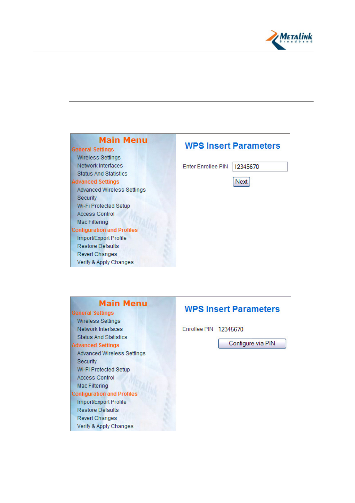
11. In the AP, click Configure via PIN.
The WPS Insert Parameters page appears.
12. In the Enter Enrollee PIN field, enter the PIN of the STA (Enrollee).
13. Click Next.
The following page appears:
14. Click Configure via PIN.
The AP will search for the corresponding STA.
Revision 2.3.5 Page 44 of 69
Page 45
WLANPlus -
15. In the STA, in the Manual AP Selection field, do one of the following:
Select Yes if you wish to select the AP from an AP list.
Select No if you wish to automatically connect to the first available and
matching AP.
16. Click Get configured via PIN.
If you have selected the No option in the Manual AP Selection field, the
STA will connect to the AP and the Successful Registration page displays the
security type of the ESSID you have selected.
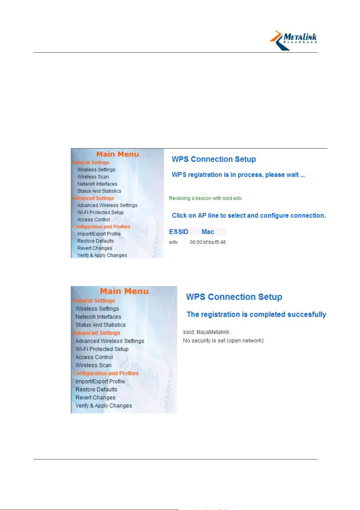
If you have selected the Yes option in the Manual AP Selection field, the WPS
Connection Setup page appears. Proceed to the next step.
17. Select the ESSID you want.
The Successful Registration page displays the security type of the ESSID you
selected.
Revision 2.3.5 Page 45 of 69
Page 46
WLANPlus -
Configuring WPS via PBC
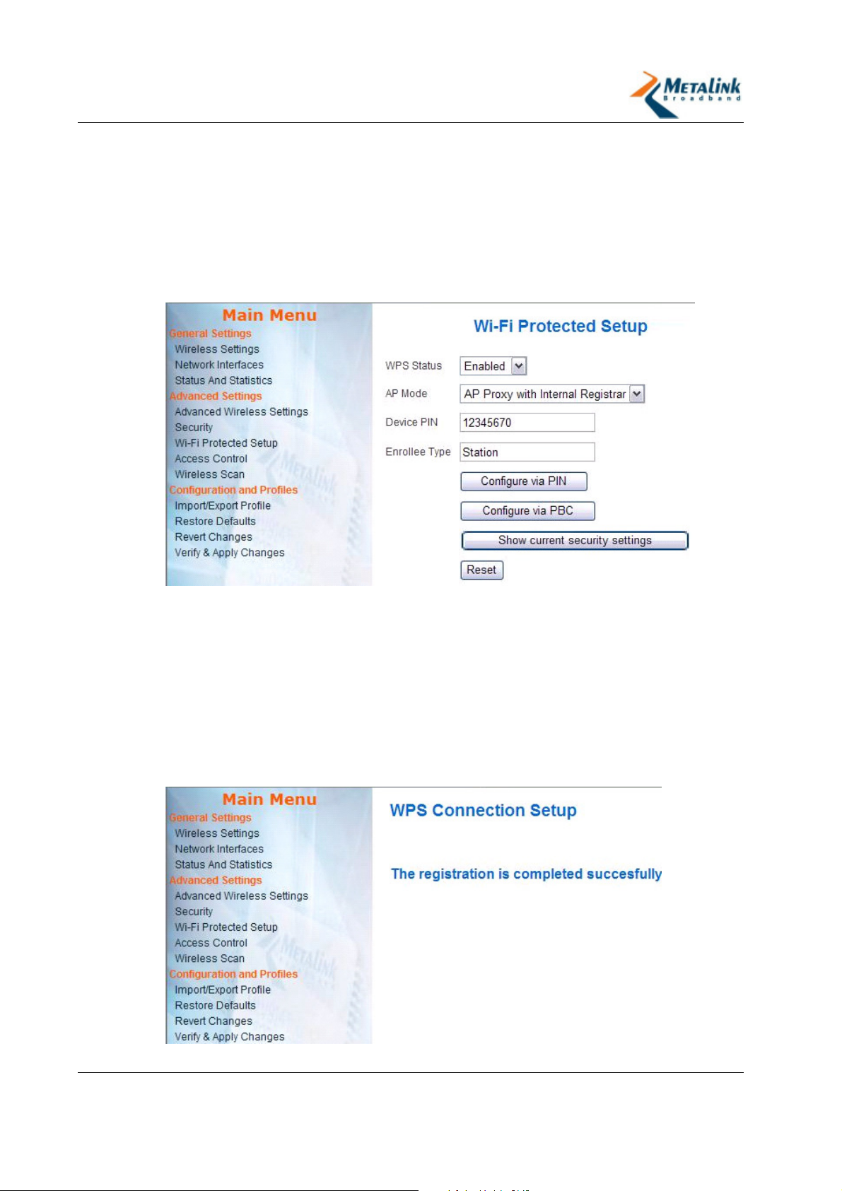
The following procedure enables you to connect to the Wi-Fi Protected Setup by
using the Push Button Control of the devices you want to connect:
To configure WPS via PBC:
1. In the AP’s Configuration Management interface go to Advanced Settings >
Wi-Fi Protected Setup.
The Wi-Fi Protected Setup page appears:
2. In the WPS Status field, select Enabled.
3. In the AP Mode field, select AP Proxy with Internal Registrar.
4. In the Device PIN field, enter the PIN number of the device.
5. In the Enrollee Type field, enter the word Station.
6. To view the settings of the AP, click Show Current Security Settings.
7. Click Configure via PBC.
8. Press the hardware button of both devices at the same time.
The devices connect to one another, and the Successful Registration page
appears.
Revision 2.3.5 Page 46 of 69
Page 47

WLANPlus -
4.3.5 Access Control
The Access Control page defines the Aggregation and WMM settings for the
following access categories:
Background
Best Effort
Video
Voice
Each access category is configured separately by configuring the following settings:
Parameter Description Values
Use Aggregation
<access category>
Accept Aggregation
<access category>
Max Number of
Packets in aggregation
Background <access
category>
Max. Aggregation Size
Background <access
category>
Timeout Interval
Background <access
category>
Min size of packet in
Aggregation
Background <access
category>
ADDBA timeout
Background <access
category>
Defines whether or not the MAC will set
up an ADDBA session.
Defines whether or not the MAC will
accept an ADDBA request.
Defines the maximum number of packets
(sub-frames) in the aggregate.
Defines the maximum size of the
aggregate (in bytes).
Defines the timeout period (in time units,
TU, where 1TU = 1024 µs) in which the
aggregate should be closed with a
“closing condition” before it is closed by
the timer.
Defines the minimum size (in bytes) of a
packets to be accumulated into the
aggregate.
Defines the duration, in TUs, after which
the ADDBA setup is terminated, if there
are no frame exchanges within this
duration by the Block Ack agreement.
Yes
No
Yes
No
??
0 = disables
the timeout
Aggregation Window
Size Background
<access category>
CW min for STA
Background <access
category> (AP Only)
CW max for STA
Background <access
category> (AP Only)
AIFSN for STA
Background <access
category> (AP Only)
Revision 2.3.5 Page 47 of 69
??
Defines the minimum contention window
limit from which the random backoff is
computed for an STA in BSS.
Defines the maximum contention window
limit from which the random backoff is
computed for an STA in BSS.
Arbitration Interframe Space Number for
an STA in the BSS.
Page 48

WLANPlus -
Parameter Description Values
TXOP for STA
Background <access
category> (AP Only
CW min for AP
Background <access
category> (AP Only)
CW max for AP
Background <access
category> (AP Only)
AIFSN for AP
Background <access
category> (AP Only)
TXOP for AP
Background <access
category> (AP Only
Transmission opportunity for an STA in
the BSS.
The contention window limits from which
the random backoff is computed for AP.
The contention window limits from which
the random backoff is computed for AP.
Arbitration interframe space number for
AP.
Transmission opportunity for AP.
4.4 Configuration and Profiles
WLANPlus features the ability to create and use configuration profiles. The
configuration profiles are predefined configuration settings that can be used at any
time.
4.4.1 Import/Export Configuration
Configuration settings can be imported and exported to a PC.
To import a configuration file:
1. Connect the Evaluation Kit to the PC from which you wish to import the file.
2. In the Configuration Management interface, go to Configuration and Profiles
> Import/Export Profile.
3. Click Browse.
4. Select the configuration file you wish to upload (saved before).
5. Click Upload.
To export a configuration file:
1. Connect the Evaluation Kit to the PC to which you wish to export the file.
2. In the Configuration Management interface, go to Configuration and Profiles
> Import/Export Profile.
3. Click Download.
Revision 2.3.5 Page 48 of 69
Page 49
WLANPlus -
4.4.2 Restore Defaults (AP)
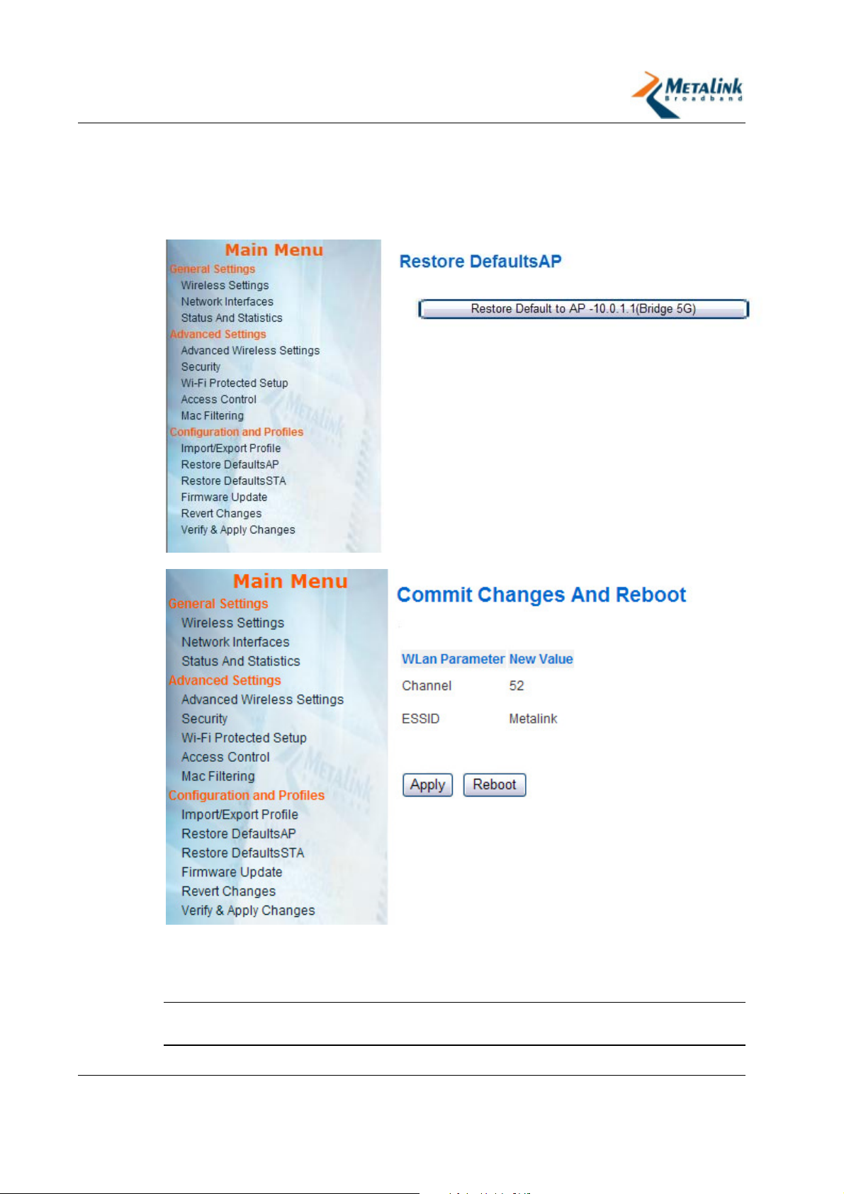
To load a Default Profile for AP
1. From the Main Menu, select Restore Defaults AP.
2. Click the Restore defaults button.
The list of changed and updated parameters appears:
To save the configuration, click Apply. If some parameters needed to be
changed, change them then apply the changes and reboot. (For example, to
set a unique ESSID, ) go to the wireless setting screen, change the ESSID, click
Apply then click Reboot.
N
OTE
:
If the device is restarted without applying the changes, the changes will
not be saved.
Revision 2.3.5 Page 49 of 69
Page 50
WLANPlus -
4.4.3 Restore Defaults (Station)
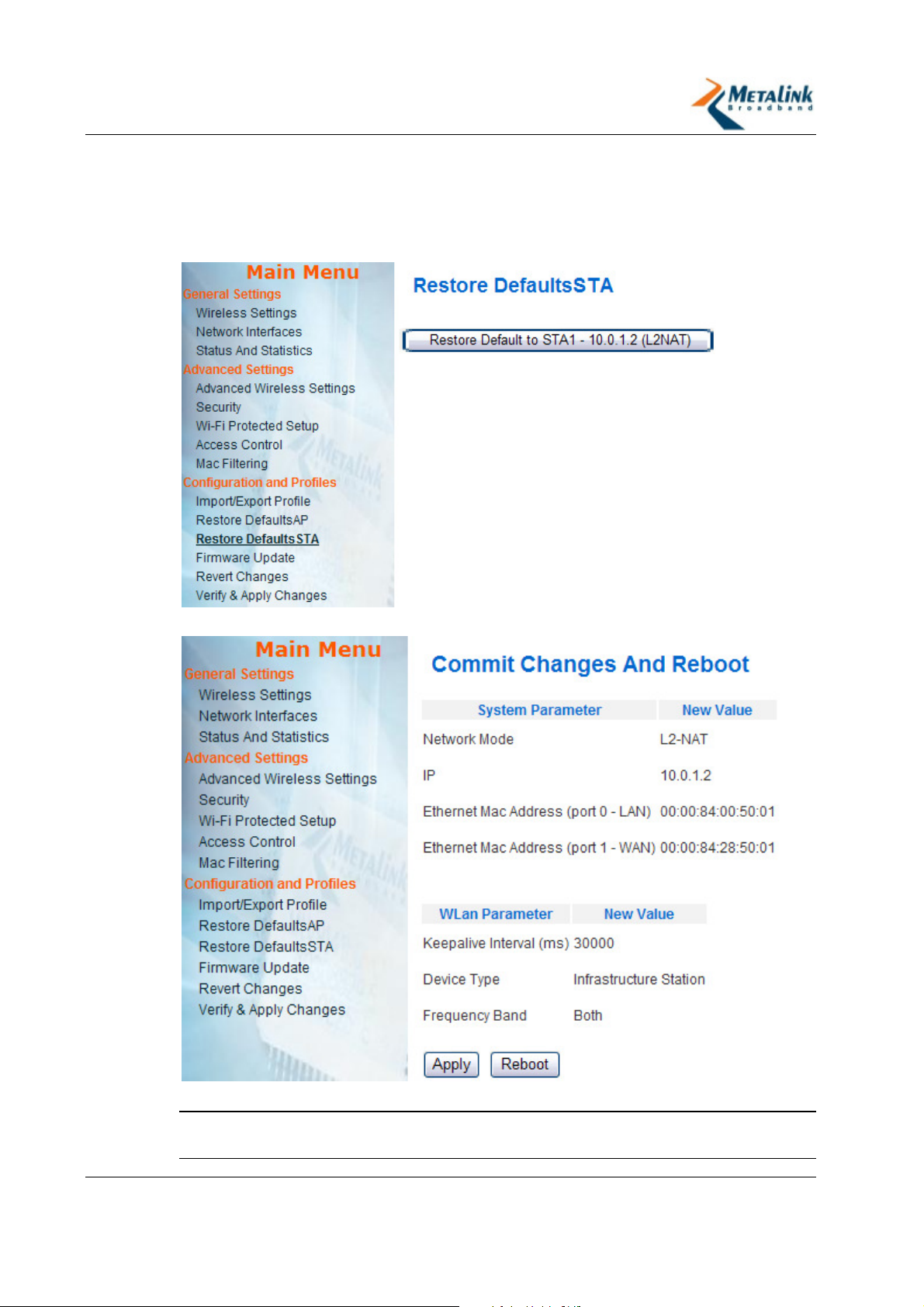
To load a Default Profile for station (Video Bridge)
1. From the Main Menu, select Restore Defaults STA.
2. Click the Restore defaults button.
3.
The list of changed and updated parameters appears:
4.
To save the configuration, click Apply.
N
OTE
:
If the device is restarted without applying the changes, the changes will
not be saved.
Revision 2.3.5 Page 50 of 69
Page 51
WLANPlus -
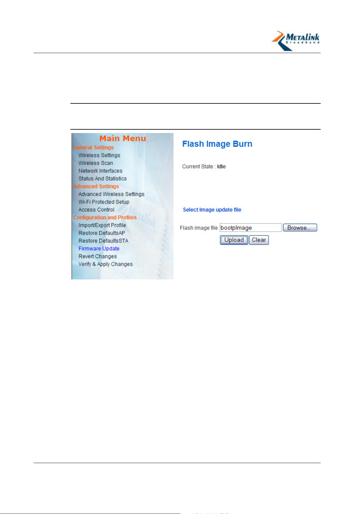
4.4.4 Firmware Updates
To update firmware version to a device
1. From the Main Menu, click Firmware Update.
2. Click Browse and select the new firmware file to be loaded.
N
OTE
:
Ensure you select the file with the new firmware version. The file name
must be “bootpImage”. Other files will not be uploaded to protect from burning
wrong file.
Revision 2.3.5 Page 51 of 69
Page 52
WLANPlus -
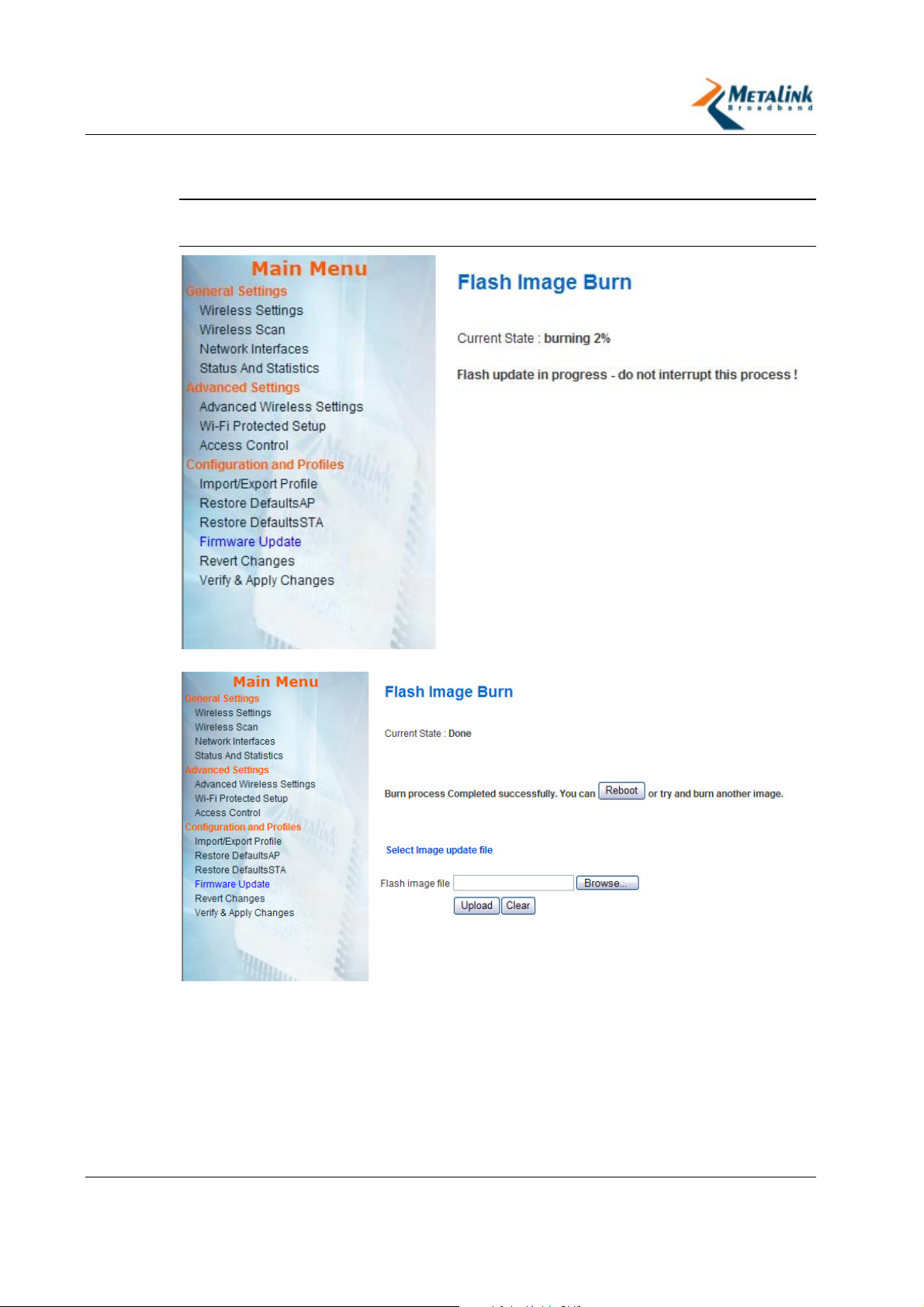
3. To start the firmware update process, click Upload.
The percentage of the burning process will appear on the screen.
I
MPORTANT
:
Before the upgrade completes, do not interrupt the process,
reboot the device, or turn off the power.
When the new Firmware update is finished, a notification appears.
4. Click Reboot.
After the firmware update is complete, it is advised to restore the defaults to
verify that the new functions in the updated firmware are working correctly. For
instructions, see Restore Defaults (AP) (page 49) or Restore Defaults (Station)
(page 50).
Revision 2.3.5 Page 52 of 69
Page 53

WLANPlus -
4.4.5 Revert Changes
The Revert Changes module contains the following functions that control H/W
settings:
Revert – reverts to the previous configuration settings
Reboot – reboots the Evaluation Kit
To revert to previous settings:
1. In the Configuration Management interface, go to Configuration and Profiles
> Revert Changes.
2. Click Revert.
3. Click Apply.
To reboot the Evaluation Kit:
1. In the Configuration Management interface go to Configuration and Profiles
> Revert Changes.
2. Click Reboot.
4.4.6 Verify and Apply Changes
The Verify and Apply Changes function performs a global commit of the changes
made.
To verify and apply changes:
1. In the Configuration Management interface go to Configuration and Profiles
> Verify and Apply Changes.
The Commit Changes And Reboot window opens.
2. To apply the changes, click Apply.
-orTo reboot the AP/STA, click Reboot.
Revision 2.3.5 Page 53 of 69
Page 54

WLANPlus -
5. Streaming Video over WLANPlus
In this chapter
Overview ................................................................ 54
Installing the VideoLAN Media Player .......................... 54
Streaming Video with VideoLAN Media Player .............. 55
Receiving Video with VideoLAN Media Player ............... 57
Setting VideoLAN Media Player for Multicast Mode........ 57
Installing NFS.......................................................... 58
5.1 Overview
This chapter describes two ways to stream video from the AP to the STA(s):
Unicast Streaming – a straightforward method for video streaming. The
WLANPlus evaluation kit CD-ROM includes a Unicast streaming program called
VideoLAN Media Player. VideoLAN is used for both streaming and receiving or
playing-back the video stream. Therefore, it should be installed on both the
Video Streamer and the Video Receiver. This method does not incorporate a
retransmission mechanism, and it is therefore more susceptible to video
glitches.
NFS Streaming – NFS is Linux's "Network File System". It may be used to
stream video. This method includes a retransmission mechanism, which reduces
its susceptibility to video glitches caused by link interferences.
5.2 Installing the VideoLAN Media Player
The VideoLAN Media Player should be installed on both the Video Streamer and the
Video Receiver. If you wish to stream to more than one station simultaneously, you
will need to run a different instance of VideoLAN Media Player to play each stream
separately.
To Install VideoLAN Media Player on the Video Streamer:
1. Insert the WLANPlus CD-ROM into the Video Streamer CD-ROM drive.
2. Open the VideoLAN folder.
3. Double click vlc-0.8.5-win32.exe
4. Follow the on-screen instructions.
For Linux-based Video Streamers, VideoLAN should be available as part of your
Linux distribution package. Refer to the OS documentation for installation
instructions.
Revision 2.3.5 Page 54 of 69
Page 55
WLANPlus -
To install VideoLAN Media Player on the Video Receiver:
1. Insert the WLANPlus CD-ROM into the Video Streamer CD-ROM drive.
2. Open the VideoLAN folder.
3. Double click vlc-0.8.5-win32.exe
4. Follow the on-screen instructions.
To setup multiple stations, repeat for each station.
5.3 Streaming Video with VideoLAN Media Player
To stream to more than one station simultaneously, you will need to run a different
instance of VideoLAN Media Player for each stream.
To run VideoLAN Media Player on the Video Streamer:
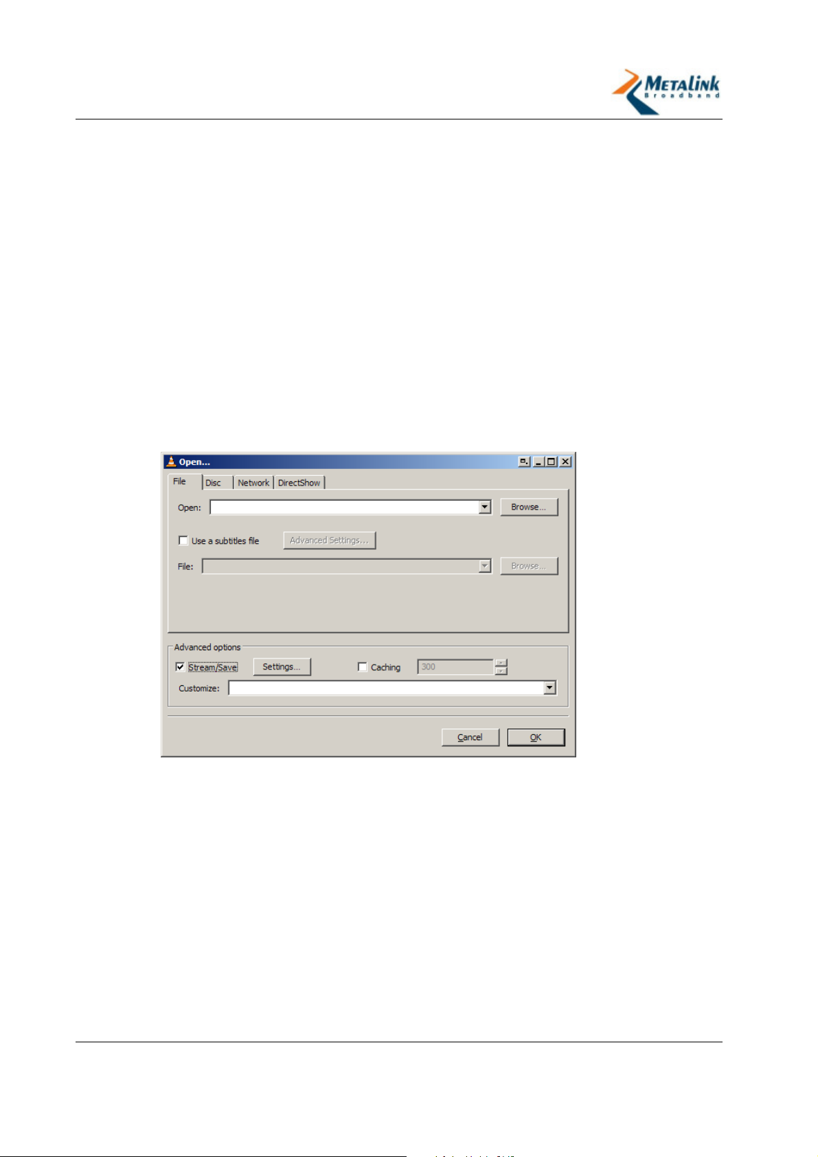
1. From the Start >Programs menu, select VideoLAN Media Player.
2. From the File menu select Open File.
The Open… window appears with the File tab selected.
3. Select the Stream/Save checkbox at the bottom.
Revision 2.3.5 Page 55 of 69
Page 56
WLANPlus -
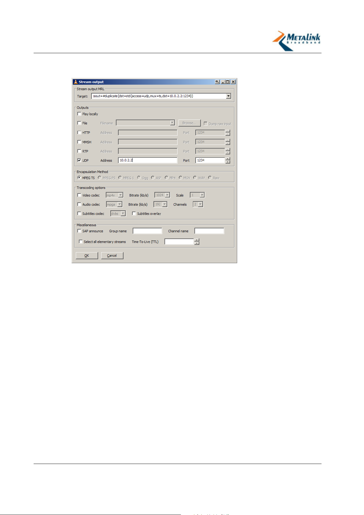
4. Click Settings.
The Stream Output window appears.
5. Do one of the following:
For UDP output, check the UDP checkbox.
For RTP output, check the RTP checkbox.
6. Enter the IP address of the Video Receiver (destination) into the Address field.
7. Enter the Port number of the Video Receiver into the Port field. The default
number, “1234”, can be used unless you required otherwise.
8. Click OK.
9. In the Open window click Browse.
A file system window appears.
10. Select the file you wish to stream.
11. Click OK.
12. To stream to more than one station simultaneously, install an additional
instance of VideoLAN Media Player and repeat the procedure.
Revision 2.3.5 Page 56 of 69
Page 57
WLANPlus -
5.4 Receiving Video with VideoLAN Media Player
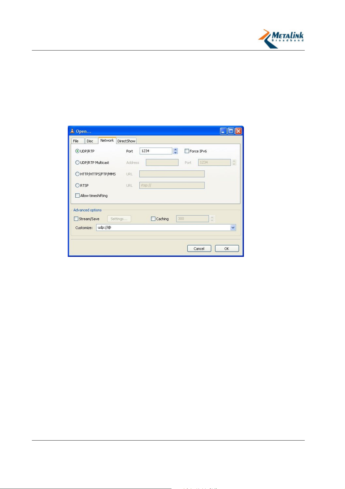
The video stream can be played back by a separate instance of VideoLAN Media
Player that is installed on the Video Receiver.
To run VideoLAN Media Player on the Video Receiver:
1. From the Start >Programs menu, select VideoLAN Media Player.
2. From the File menu select Open Network Stream.
The Open Network Stream window appears with the Network tab selected.
3. Select UDP/RTP (default).
4. Enter the Port number in the Port field. If you did not change the default value
on the Video Streamer’s port settings (1234), use the default value.
5. Click OK.
5.5 Setting VideoLAN Media Player for Multicast Mode
Considering that proper multicast configuration was set in the Evaluation Kit,
different configurations of the VLC are required.
To configure the VLC at the AP:
1. In the VLC program, click File > Open File and select a file to be streamed.
2. Click Settings, in the Send to a multicast field, enter the following multicast
address: 225.0.0.0 to 239.255.255.255
3. Under Miscellaneous, change the TTL (Time to Live) field to 4.
4. Click OK.
To configure the VLC at the STA:
1. In the VLC program, click File >Open Network Stream.
2. Under Settings, in the UDP/RTP Multicast field, enter the address as set in the
AP side as multicast.
3. Click OK.
Revision 2.3.5 Page 57 of 69
Page 58

WLANPlus -
5.6 Installing NFS
The NFS (Network File System) offers a good solution to streaming video over UDP
in problematic link interference conditions. To use NFS, you will need to install an
NFS Server on the Video Streamer, and an NFS Client on the Video Receiver.
Although instructions are given for Red Hat Linux systems, the information is
relevant for other Linux distributions as well.
To install an NFS server on a Linux-based Video Streamer:
1. From the Application menu, open System Settings and select Services.
The Services window appears.
2. Select the NFS checkbox.
3. Create a new directory (for example, "/shared"). This directory will be exported
to the NFS clients.
4. Locate the video file to be streamed and copy it into this directory.
5. To define the directories to be exported to the NFS clients and their access
rights, edit the /etc/exports file as follows: <path> <ip_mask> (permission,
access type)
For example:
#
/shared 10.10.*.*(ro,sync)
Available parameters:
Path (for example, /shared) - Name of the directory containing the video
files to be shared
IP Mask (for example, 10.10.*.*) - IP mask for addresses that are allowed
to access this directory
Permissions (for example, ro) - The access type for each IP mask
Access Type (for example, sync) - Specifies whether the access is
synchronous or asynchronous
6. For these changes to take affect do one of the following:
Restart the Video Streamer.
Call "/etc/rc.d/nfsserver restart" (this may not work on every Linux
distribution).
The NFS server is now installed.
To install and setup NFS Server on the a Windows-based Video Streamer:
1. Insert the WLANPlus CD-ROM into the Video Streamer CD-ROM drive.
2. Open the nfsAxe folder.
3. Double click the setup.exe file.
4. Follow the on-screen instructions.
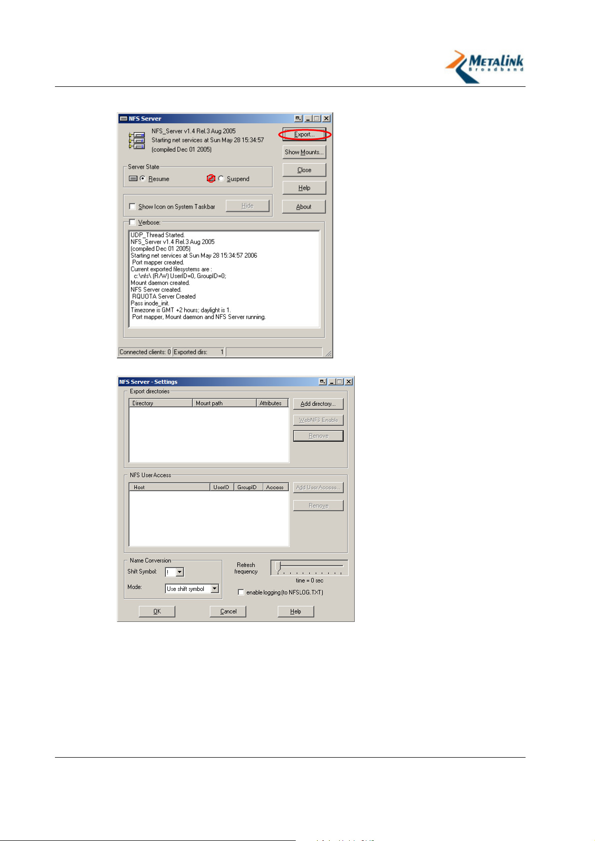
5. Launch the NFS server from the Programs menu.
6. First time users only - Click Yes to create a list of exported directories.
Revision 2.3.5 Page 58 of 69
Page 59
WLANPlus -
7. In the NFS Server screen, click Export.
The NFS Settings screen appears:
8. Click Add Directory and select the directory you want to export.
Revision 2.3.5 Page 59 of 69
Page 60
WLANPlus -
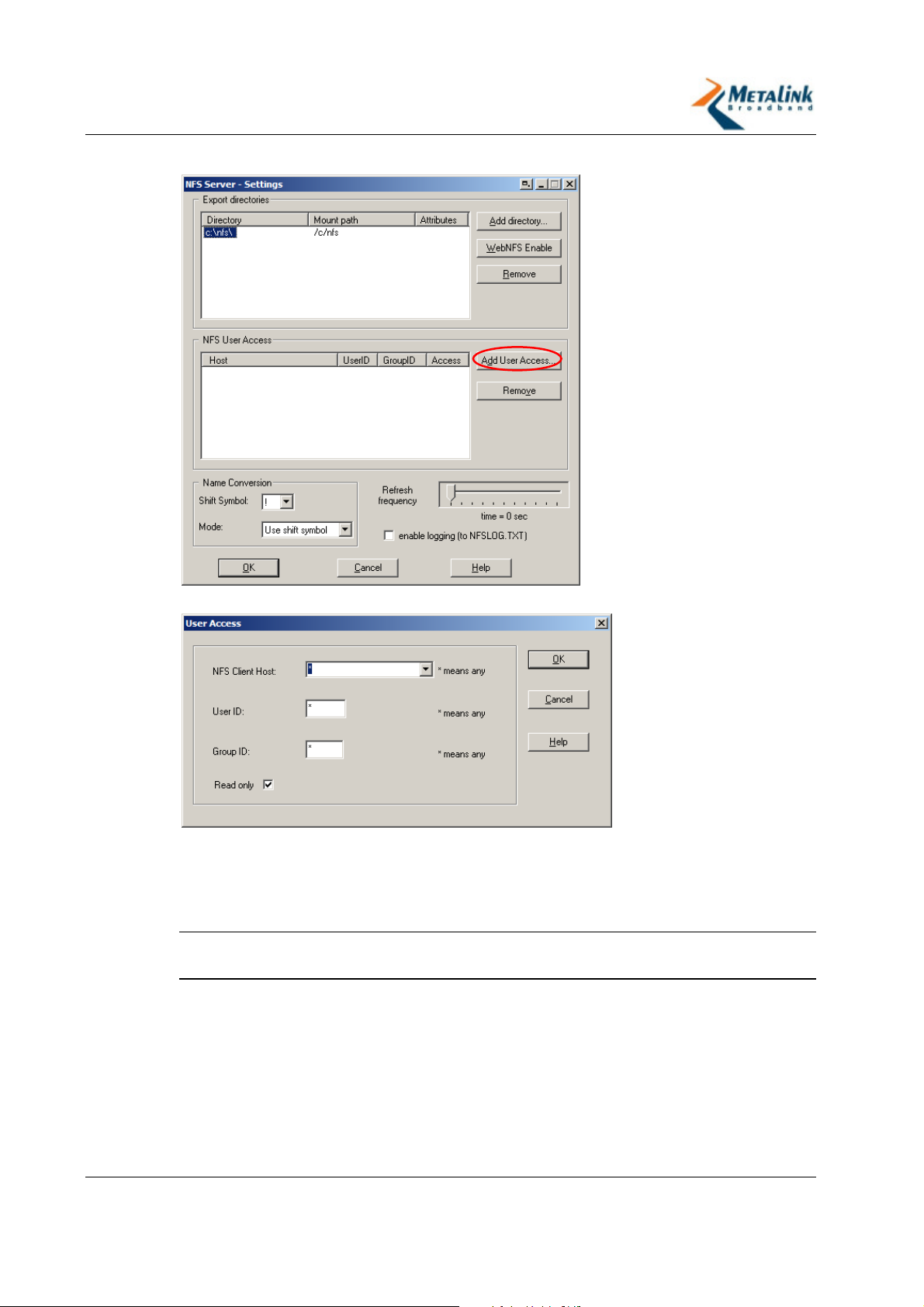
9. Select the directory, and click Add User Access.
The User Access window appears:
10. To restrict access enter one of the following:
A specific NFS Client Host
A specific User ID
A specific Group ID
TIP:
If you do not want to restrict access to the shared content, do not make
any changes and click OK.
11. Click OK.
Revision 2.3.5 Page 60 of 69
Page 61
WLANPlus -
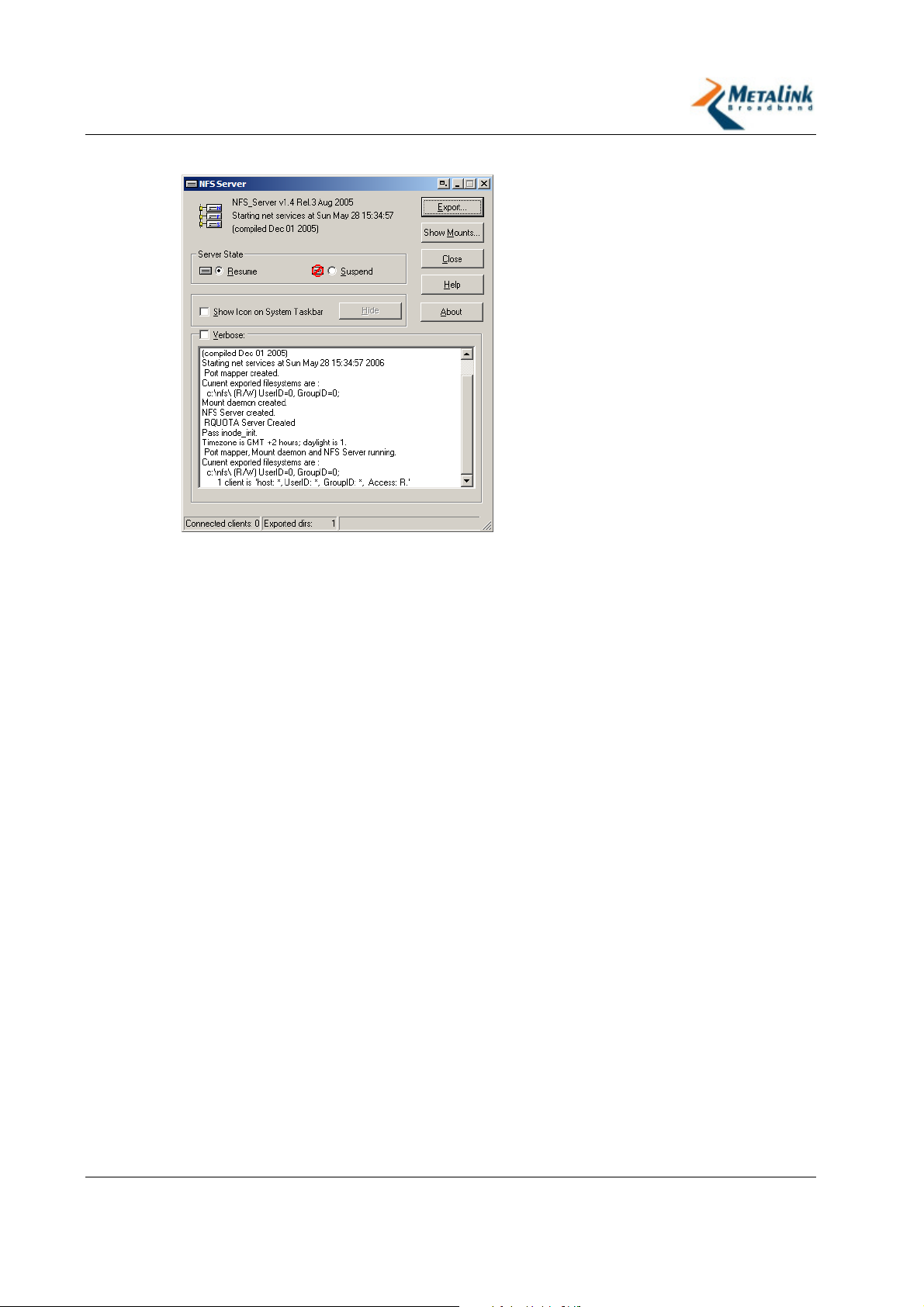
12. In Server State select Resume.
The NFS Server is ready.
In order to access the folder exported by the NFS server, you need to perform a
“mount” operation.
To setup NFS Client on a Linux-based Video Receiver:
1. Create a local folder in the video receiver file system. This folder will be the
mount point. For example, the folder named can be called “/mounted”.
2. Call the “mount” command: mount –t nfs server-IP:/shared /mounted
The new folder is mapped to the remote folder “/shared” on the NFS server.
3. Try to access “/mounted” and check that you can see the files stored on the NFS
server under the folder “/shared”.
The procedure below describes a quicker method for performing mounts and
should be used to perform multiple “mounts”.
To setup NFS Client on a Linux-based Video Receiver to perform "multi-
mounts":
1. Open the /etc/fstab file.
2. Add the following line:
<server>:</path/of/dir> </local/mnt/point> nfs <options> 0 0
For example:
Server-IP:/shared /mounted nfs –o rsize=8192,wsize=8192,intr
3. Call the “mount” command: mount –a nfs server-IP:/shared /mounted
The new folder is mapped to the remote folder “/shared” on the NFS server.
4. Try to access “/mounted” and check that you can see the files stored on the NFS
server under the folder “/shared”.
Revision 2.3.5 Page 61 of 69
Page 62

WLANPlus -
A
Appendix A: Default Settings for
AP Profile
AP - band 5.2Ghz HT CB Aggr Bridge mode Addr 10.0.1.1
Page Name Parameter Name Value
Device Type Access Point
Wireless settings
Network Interfaces
Frequency Band If the board supports 5GHz
this is the frequency,
otherwise 2.4 Ghz.
Channel Auto
Spectrum BW
usage
Secondary channel
offset
ESSID Metalink
IP 10.0.1.1
Subnet 255.255.255.0
Ethernet Mac
Address (port 0 LAN)
Ethernet Mac
Address (port 1 WAN)
Network mode Bridge
Wireless LAN Mac
Address
40MHz
Upper
00:00:84:00:50:99
00:00:84:28:50:99
Received from the module’s
EEPROM
Use LDPC Yes
Use Hidden SSID No
ERP Protection Type RTC/CTS
Use Overlapping
BSS Protection
11n Protection Type RTC/CTS
Revision 2.3.5 Page 62 of 69
Yes
Page 63

WLANPlus -
Page Name Parameter Name Value
Enable AP
forwarding
Use reliable multicast
Percentage of
maximal transmit
power
WPS Status
Current Security
Mode
Wi-Fi Protected Setup Maximum number
of allowed
connections
Security Access control
mode
Use Aggregation NO MAC Filtering
Accept Aggregation Yes
Max. Number Of
Packets in
aggregation
Max. Aggregation
size
Yes
Yes
100%
Disabled
Open
16
Open
7
12000
Access Control Background
Access Control – Best
Effort
Timeout Interval 3
Min. size of packet
10
in Aggregation
ADDBA timeout 0
Aggregation
64
Window Size
CW min for STA 15
CW max for STA 1023
AIFSN for STA 7
TXOP for STA 0
CW min for AP 15
CW max for AP 1023
AIFSN for AP 7
TXOP for AP
0
Use Aggregation Yes
Accept Aggregation Yes
Max. Number Of
10
Packets in
aggregation
Max. Aggregation
size
Revision 2.3.5 Page 63 of 69
16000
Page 64

WLANPlus -
Page Name Parameter Name Value
Timeout Interval 3
Min. size of packet
10
in Aggregation
ADDBA timeout 0
Aggregation
64
Window Size
CW min for STA 15
CW max for STA 1023
AIFSN for STA 3
TXOP for STA 0
CW min for AP 15
CW max for AP 63
AIFSN for AP 3
TXOP for AP 0
Use Aggregation Yes
Accept Aggregation Yes
Max. Number Of
7
Packets in
aggregation
Max. Aggregation
12000
size
Access Control –
Video
Timeout Interval 3
Min. size of packet
10
in Aggregation
ADDBA timeout 0
Aggregation
64
Window Size
CW min for STA 7
CW max for STA 15
AIFSN for STA 2
TXOP for STA 3008
CW min for AP 7
CW max for AP 15
AIFSN for AP 1
TXOP for AP 3008
Use Aggregation Yes
Accept Aggregation Yes
Max. Number Of
2
Packets in
aggregation
Revision 2.3.5 Page 64 of 69
Page 65

WLANPlus -
Page Name Parameter Name Value
Max. Aggregation
10000
size
Timeout Interval 10
Min. size of packet
10
in Aggregation
ADDBA timeout 0
Access Control –
Aggregation
Window Size
CW min for STA 3
CW max for STA 7
64
Voice
AIFSN for STA 2
TXOP for STA 1504
CW min for AP 3
CW max for AP 7
AIFSN for AP 1
TXOP for AP 1504
Revision 2.3.5 Page 65 of 69
Page 66

WLANPlus -
B
Appendix B: Default Settings for
STA(x) Profile
STA1 HT Aggr WDS mode Addr 10.0.1.2
Page Name Parameter Name Value
Device Type Infrastructure Station
Wireless settings
Network Interfaces
Advanced Wireless
Settings
Frequency Band Depends on the board type
IP 10.0.1.2
Subnet 255.255.255.0
Ethernet Mac
Address (port 0 LAN)
Ethernet Mac
Address (port 1 LAN)
Enable bridge mode Bridging – MAC Cloning
Wireless LAN Mac
Address
Use LDPC Yes
ERP Protection Type RTS/CTS
11n Protection Type RTS/CTS
Percentage of
maximal transmit
power
Use Aggregation No
Accept Aggregation Yes
00:00:84:00:50:01
00:00:84:28:50:01
Received from the module’s
EEPROM
100%
Max. Number Of
Packets in
aggregation
Max. Aggregation
size
Revision 2.3.5 Page 66 of 69
7
12000
Page 67

WLANPlus -
Page Name Parameter Name Value
Timeout Interval 3
Min. size of packet
10
in Aggregation
Aggregation
64
Window Size
Use Aggregation Yes
Accept Aggregation Yes
Max. Number Of
10
Packets in
aggregation
Access Control – Best
Max. Aggregation
size
16000
Effort
Timeout Interval 3
Min. size of packet
10
in Aggregation
ADDBA timeout 0
Aggregation
64
Window Size
Use Aggregation Yes
Access Control –
Video
Access Control – Voice
Accept Aggregation Yes
Max. Number Of
7
Packets in
aggregation
Max. Aggregation
12000
size
Timeout Interval 3
Min. size of packet
10
in Aggregation
ADDBA timeout 0
Aggregation
64
Window Size
Use Aggregation Yes
Accept Aggregation Yes
Max. Number Of
2
Packets in
aggregation
Max. Aggregation
10000
size
Timeout Interval 10
Revision 2.3.5 Page 67 of 69
Page 68

WLANPlus -
Min. size of packet
in Aggregation
ADDBA timeout 0
10
Aggregation
Window Size
Wi-Fi Protected Setup
Wireless Scan ESSID / Wildcard Empty
WPS Status
64
Disabled
Revision 2.3.5 Page 68 of 69
Page 69

WLANPlus -
L
6. Index
LED Indicators..............................13
A
Access Control............................. 47
Accessing the WLANPlus Configuration
Menu..................................... 24
Acronyms and Glossary Terms ........ 5
Advanced Settings .................. 24, 34
Advanced Wireless Settings .......... 34
Appendix A
Default settings for AP Profile ... 62
Appendix B
Default settings for STA(x) Profile
........................................ 66
Assigning an IP Address ............... 17
C
CD-ROM ..................................... 13
Changing Configuration Settings.... 24
Configuration and Profiles ........ 24, 48
Configuring Route Mode ............... 30
Configuring WPS via PBC .............. 46
Configuring WPS via PIN............... 43
Connecting STAs to the AP............ 20
Connecting the Evaluation Kit to the
Video Streamer/Receiver ......... 16
G
General Overview .......................... 8
General Settings..................... 24, 25
Getting Started ........................... 15
MTW_RGPLUS_5.0_VB_001 Video
Bridge ................................... 11
GPB 244 / 236 RG Board .............. 13
I
Import/Export Configuration ......... 48
Installing NFS ............................. 58
Installing the VideoLAN Media Player
............................................ 54
Introduction to the WLANPlus
Evaluation Kit ........................... 8
Revision 2.3.5 Page 69 of 69
N
Network Interfaces .......................26
O
Overview .....................................15
P
Package Contents .........................10
Physical Description ......................11
Powering Up the Evaluation Kit.......20
R
Receiving Video with VideoLAN Media
Player.....................................57
Restore Defaults ................49, 50, 51
Revert Changes ............................53
Revision History ............................ 7
S
Security (AP Only) ........................37
Setting Open Security (no encryption)
....................................... 37, 38
Setting Up the Evaluation Kit
(AP/STA) ................................16
Setting VideoLAN Media Player for
Multicast Mode ........................57
Setting WEP Security .............. 37, 39
Setting WPA/WPA2-Enterprise
Security............................ 37, 41
Setting WPA/WPA2-Personal Security
....................................... 37, 40
Status and Statistics .....................33
Streaming Video over WLANPlus.....54
Streaming Video with VideoLAN Media
Player.....................................55
V
Verify and Apply Changes ..............53
W
Wi-Fi Protected Setup ...................43
Wireless Settings ..........................25
 Loading...