

Page 1
Edition
MOVIMOT® MM..C
08/2003
Operating Instructions
11218126 / EN
Page 2

SEW-EURODRIVE
Page 3

Contents
1 Important Notes................................................................................................. 5
2 Safety Notes ...................................................................................................... 7
3 Unit Design........................................................................................................ 8
3.1 MOVIMOT
3.2 Unit designations (MOVIMOT
3.3 MOVIMOT
3.4 Unit designations (MOVIMOT
4 Mechanical Installation...................................................................................16
4.1 MOVIMOT
4.2 Modular terminal box .............................................................................. 17
4.3 Mounting MOVIMOT
4.4 Option MLU..A / MLG..A / MLK11A ........................................................ 20
4.5 MBG11A option....................................................................................... 21
4.6 MWA21A option...................................................................................... 21
4.7 URM option............................................................................................. 22
5 Electrical Installation of MOVIMOT
5.1 Installation instructions............................................................................ 23
5.2 Connection of MOVIMOT
5.3 MOVIMOT
5.4 Connection MOVIMOT
5.5 Connection RS-485 bus master..............................................................31
5.6 Connection between MOVIMOT
6 Electrical Installation with Integrated AS-Interface ..................................... 37
6.1 Installation instructions............................................................................ 37
6.2 Connection options with integrated AS-Interface....................................39
6.3 Connection of MOVIMOT
6.4 Connection of MOVIMOT
6.5 Connection of MOVIMOT
6.6 Connection of URM option......................................................................45
6.7 Connection between MOVIMOT
7 Startup of Standard Design............................................................................ 51
7.1 Important startup instructions.................................................................. 51
7.2 Description of the controls ...................................................................... 51
7.3 Description of the DIP switches S1.........................................................53
7.4 Description of the DIP switches S2.........................................................55
7.5 Selectable special functions MM..C-503-00............................................ 58
7.6 Startup with binary control (control via terminals)................................... 77
7.7 Startup with options MBG11A or MLG11A ............................................. 79
7.8 Startup with MWA21A option (speed control module)............................ 82
7.9 Startup with external AS-i binary slave MLK11A .................................... 85
7.10 Additional information for mounting close to the motor...........................88
8 Startup with Integrated AS-Interface............................................................. 90
8.1 Important startup instructions.................................................................. 90
8.2 Description of the controls ...................................................................... 90
8.3 Description of the DIP switches S3.........................................................92
8.4 Description of the DIP switches S4.........................................................94
8.5 Selectable special functions MM..C-503-30............................................ 95
8.6 Startup procedure................................................................................. 102
8.7 Advanced startup with MOVITOOLS.................................................... 106
8.8 Additional information for mounting close to the motor.........................115
9 Startup with Communications Interface / Fieldbus ................................... 117
9.1 Startup procedure................................................................................. 117
9.2 Coding of process data......................................................................... 119
9.3 Function with RS-485 master................................................................ 122
®
inverter (standard design)..................................................... 8
®
inverter (with integrated AS-Interface)................................ 12
®
gearmotor ...........................................................................16
®
inverter with option P2.A close to the motor ....... 19
®
plug connectors .................................................................. 26
®
standard design) .....................................9
®
with integrated AS-Interface) ................13
®
Standard Design................................ 23
®
basic unit ..................................................... 25
®
options ............................................................ 27
®
and motor mounting close to motor... 32
®
MM../AVSK (connection option A)............... 42
®
MM../AZSK (connection option B)............... 43
®
MM../AND3/AZSK (connection option C) .... 44
®
and motor mounting close to motor .. 46
Operating Instructions – MOVIMOT® MM03C - MM3XC
3
Page 4

Contents
10 Diagnostics....................................................................................................127
10.1 Diagnostics of MOVIMOT
10.2 Diagnostics of MOVIMOT
®
standard design ........................................ 127
®
with integrated AS-Interface...................... 132
10.3 Important service information................................................................ 140
11 Inspection and Maintenance........................................................................ 141
11.1 Inspection and maintenance periods.................................................... 141
11.2 Inspection and maintenance work on the motor................................... 142
11.3 Inspection and maintenance work on the brake ................................... 144
11.4 Permitted ball bearing types ................................................................. 148
11.5 Working air gap, braking torque, brake.................................................148
12 Technical Data of Standard Design............................................................. 149
12.1 IEC design with connection voltages 380...500 VAC............................149
12.2 UL design with connection voltages 380500 VAC................................ 150
12.3 Technical data of options...................................................................... 151
12.4 Integrated RS-485 interface..................................................................153
12.5 Assignment of internal braking resistors............................................... 153
12.6 Assignment of external braking resistors.............................................. 154
12.7 Resistance and assignment of the brake coil ....................................... 154
13 Technical Data with Integrated AS-Interface.............................................. 155
13.1 IEC design with connection voltages 380...500 VAC............................155
13.2 Assignment of internal braking resistors............................................... 156
13.3 Assignment of external braking resistors.............................................. 156
13.4 Resistance and assignment of the brake coil ....................................... 156
13.5 URM voltage relay ................................................................................ 156
Index of Changes.......................................................................................... 157
Index...............................................................................................................158
4
Operating Instructions – MOVIMOT® MM03C - MM3XC
Page 5
1 Important Notes
Important Notes
1
Safety and warning instructions
Always follow the safety and warning instructions contained in this publication!
Electrical hazard
Possible consequences: Severe or fatal injuries.
Hazard
Possible consequences: Severe or fatal injuries.
Hazardous situation
Possible consequences: Slight or minor injuries.
Harmful situation
Possible consequences: Damage to the unit and the environment.
Tips and useful information.
Other applicable documents
Intended usage
• Operating Instructions "DR/DT/DV AC Motors, CT/CV Asynchronous Servomotors"
• If MOVIMOT
"Safe Disconnection for MOVIMOT
nents may be used in safety applications that were explicitly delivered with this
design by SEW-EURODRIVE!
• These MOVIMOT® drives are intended for industrial equipment. They comply with
the applicable standards and regulations and meet the requirements of the Low Voltage Directive 73/23/EEC.
• The use of MOVIMOT
• Technical data and information about the permitted conditions where the unit is used
can be found on the nameplate and in these operating instructions.
• It is essential to observe this specified information!
• Do not start up the unit (take it into operation in the designated fashion) until you have
established that the machine complies with the EMC Directive 89/336/EEC and that
the conformity of the end product has been determined in accordance with the Machinery Directive 89/392/EEC (with reference to EN 60204).
®
is used for emergency stops, the supplemental documentation
®
for hoist applications is limited!
®
" must be observed. Only those compo-
Operating Instructions – MOVIMOT® MM03C - MM3XC
5
Page 6

1
Important Notes
Site of operation
Waste disposal
The following uses are forbidden unless measures are expressly taken to make
them possible:
• Use in explosion-proof areas
• Use in areas exposed to harmful oils, acids, gases, vapors, dust, radiation, etc.
• Use in non-stationary applications which are subject to mechanical vibration and
shock loads in excess of the requirements in EN 50178
• Use in applications in which the MOVIMOT
functions (without master safety systems) for ensuring the safety of machinery and
people
This product consists of:
•Iron
•Aluminum
• Copper
• Plastic
• Electronic components
Dispose of all components in accordance with applicable regulations!
®
inverter undertakes independent safety
6
Operating Instructions – MOVIMOT® MM03C - MM3XC
Page 7
2 Safety Notes
• Never install damaged products or take them into operation. Please submit a com-
Safety Notes
plaint to the shipping company immediately in the event of a damage.
2
• Only electrical specialists with the relevant accident prevention training are allowed
to perform installation, startup and service work on the MOVIMOT
®
. They must also
comply with the regulations in force (e.g. EN 60204, VBG 4, DIN-VDE 0100/0113/
0160).
• Preventative measures and protection devices must correspond to the regulations in
force (e.g. EN 60204 or EN 50178).
Necessary protective measures: Grounding of MOVIMOT
®
.
• The unit meets all requirements for reliable isolation of power and electronics connections in accordance with EN 50178. All connected circuits must also satisfy the
requirements for reliable isolation so as to guarantee reliable isolation.
• Before removing the MOVIMOT
®
inverter, it must be disconnected from the supply
system. Dangerous voltages may still be present for up to one minute after disconnection from the power supply source.
• As soon as supply voltage is present at the MOVIMOT
closed, i.e. the MOVIMOT
®
inverter must be screwed on.
®
, the terminal box must be
• The fact that the status LED and other display elements are no longer illuminated
does not indicate that the unit has been disconnected from the power supply and no
longer carries any voltage.
• Mechanical blocking orunit-internal safety functions can cause a motor standstill. Removing the cause of this problem or performing a reset can result in the motor restarting on its own. If, for safety reasons, this is not permissible for the driven machine, MOVIMOT
• Danger of burns: The MOVIMOT
®
must be disconnected from the mains before correcting the fault.
®
surface temperature (especially of the heat sink)
can exceed 60 °C during operation!
• If MOVIMOT
documentation "Safe shutdown for MOVIMOT
®
or field distributors are used for emergency stops, the supplemental
®
" must be observed. Only those components may be used in safety applications that were explicitly delivered with this design by SEW-EURODRIVE!
Operating Instructions – MOVIMOT® MM03C - MM3XC
7
Page 8
3
Unit Design
MOVIMOT® inverter (standard design)
3Unit Design
3.1 MOVIMOT® inverter (standard design)
2
1
34
5
6
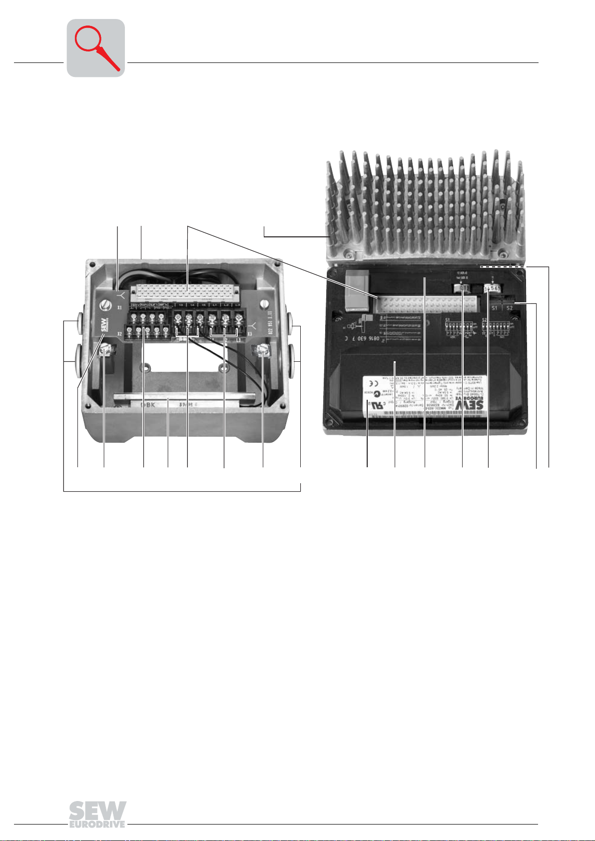
1. Identification of the circuit type
2. Terminal box (size 2 used as example)
3. Connection plug between connection unit and inverter
4. MOVIMOT
5. Connection unit with terminals
6. Screw for PE connection
7. Electronics terminal strip X2
8. Internal braking resistor BW. (standard for motors without brake)
9. Connection of brake coil (X3). For motors without brake: Connection of internal
braking resistor BW. (standard)
10.Mains connection L1, L2, L3 (X3) (suitable for 2 x 4 mm
11. Screw for PE connection
12.Cable glands
13.Electronics nameplate
14.Safety hood for inverter electronics
15.Setpoint potentiometer f1 (not visible), accessible from top of MOVIMOT
via screw fitting
16.Setpoint switch f2 (green)
17.Switch t1 for generator ramp (white)
18.DIP switches S1 and S2 (for settings see the section "Startup")
19.Status LED (visible from top of MOVIMOT
®
inverter with heat sink (size 2 used as example)
8
7
910
댷
댷
11 12
2
)
®
inverter, see the section "Diagnostics")
13
®
inverter
14 15 16
17
06496AXX
18
19
8
Operating Instructions – MOVIMOT® MM03C - MM3XC
Page 9
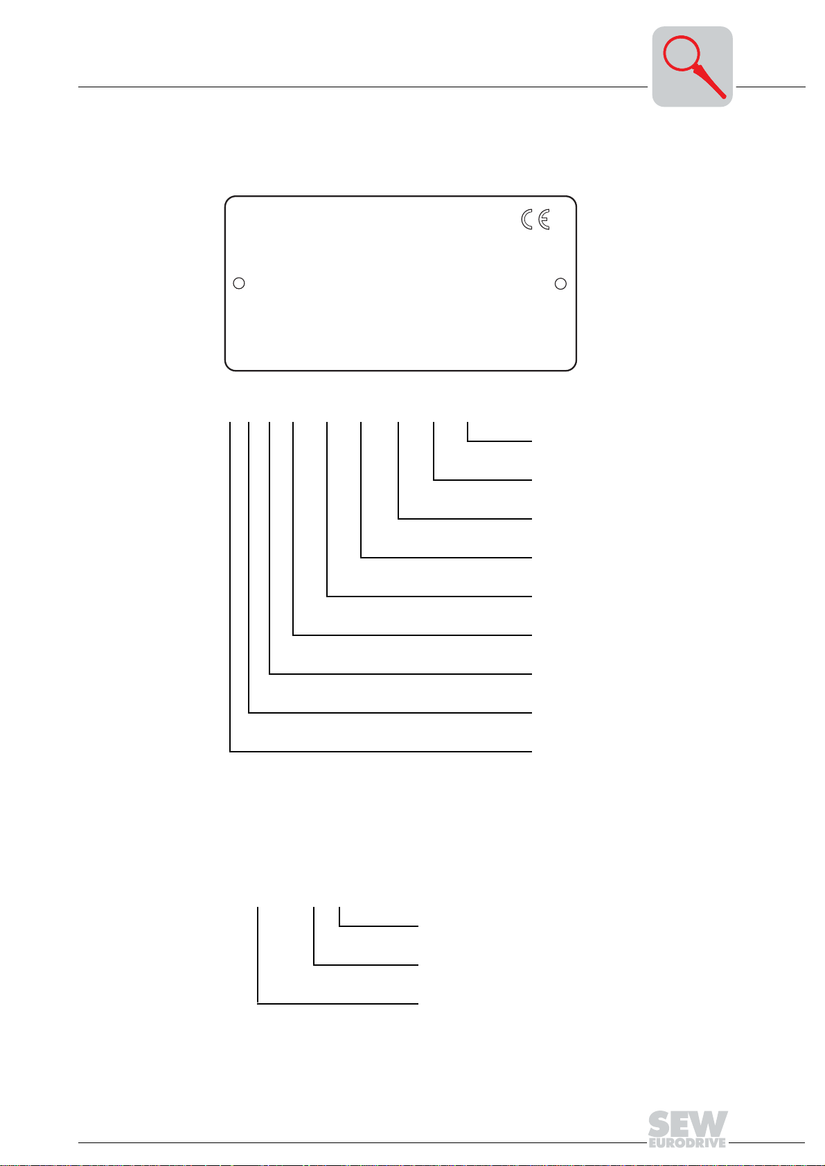
Unit designations (MOVIMOT® standard design)
3.2 Unit designations (MOVIMOT® standard design)
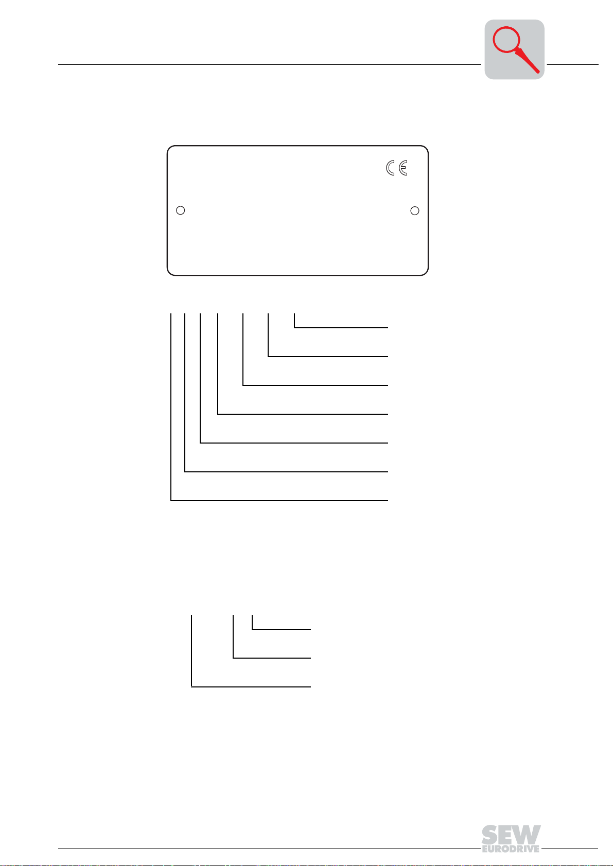
Sample motor nameplate
Unit Design
3
SEW-EURODRIVE
Typ
KA77 DT90L4/BMG/MM15/MLU
Nr.
3009818304. 0001. 99
KW
1,5/50HZ
50Hz
60Hz
r/min
Bremse
kg 73
Schmierstoff
KA 77 DT 90L4 BMG/MM15/MLU
V 380-500
V 380-500
22/1400
V 230
Ma 665
Nm 20
Nm
Bruchsal / Germany
IEC 34
3~
IM
B3
0,99
cos
j
3,50
A
A
3,50
IP
Gleichrichter
i
Made in Germany 184103 3.14
Kl
54 F
:1
64,75
06491AXX
Additional feature Inverter
MOVIMOT® frequency inverter
Additional feature motor (brake)
Size, motor pole count
Motor series
1)
Gear unit size
Gear unit series
1) Only factory-installed options are listed on the nameplate.
2) Detailed information about geared motor combinations can be found in the catalog "MOVIMOT® Geared
Motors."
2)
2)
Structure of sample fabrication number:
3009818304. 0001. 99
Final two digits of the year of manufacture
Running unit number (4 digits)
Order number (10 digits)
Operating Instructions – MOVIMOT® MM03C - MM3XC
9
Page 10
3
Unit Design
Unit designations (MOVIMOT® standard design)
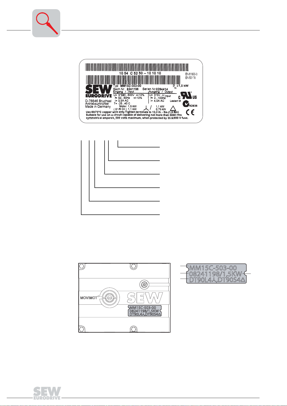
Sample inverter nameplate
MM 15 C – 503 – 00
Design (00 = Standard)
Connection type (3 = 3-phase)
Supply voltage
(50 = 380...500 V
Version C
AC
)
05605AXX
Device identification
Motor power (15 = 1.5 kW)
®
MOVIMOT
series
The device identification [1] at the top of the MOVIMOT® inverter contains information
about inverter type [2], inverter part number [3], equipment power [4] and adapted (associated) motors [5].
[2]
[3]
[5]
[1]
[4]
50862AXX
10
Operating Instructions – MOVIMOT® MM03C - MM3XC
Page 11
Unit Design
Unit designations (MOVIMOT® standard design)
3
"Mounting close
to motor" design
with option P2.A
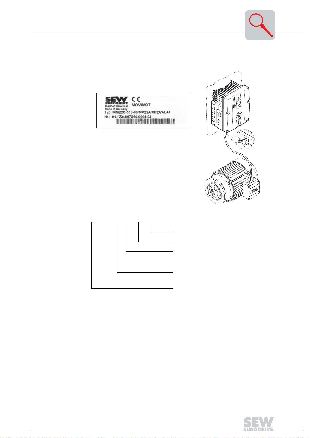
The following illustration shows an example of the MOVIMOT® inverter with option P2.A
mounted close to the motor with corresponding nameplate and unit designation:
MM22C-503-00/0/P22A/REZA/ALA4
52232AXX
Plug connector for the connection to the motor
Terminal box design
Adapter for mounting close to the motor
21 = Size 1
22 = Size 2
Circuit type
0 =
댴
1 =
쑶
MOVIMOT
®
Operating Instructions – MOVIMOT® MM03C - MM3XC
11
Page 12
3
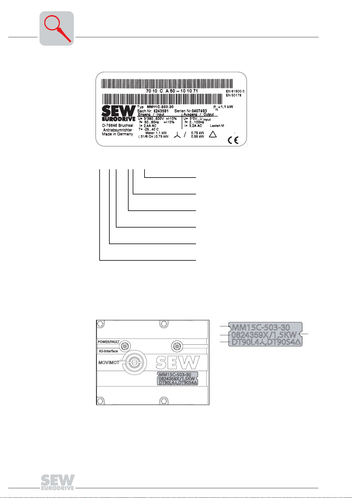
Unit Design
MOVIMOT® inverter (with integrated AS-Interface)
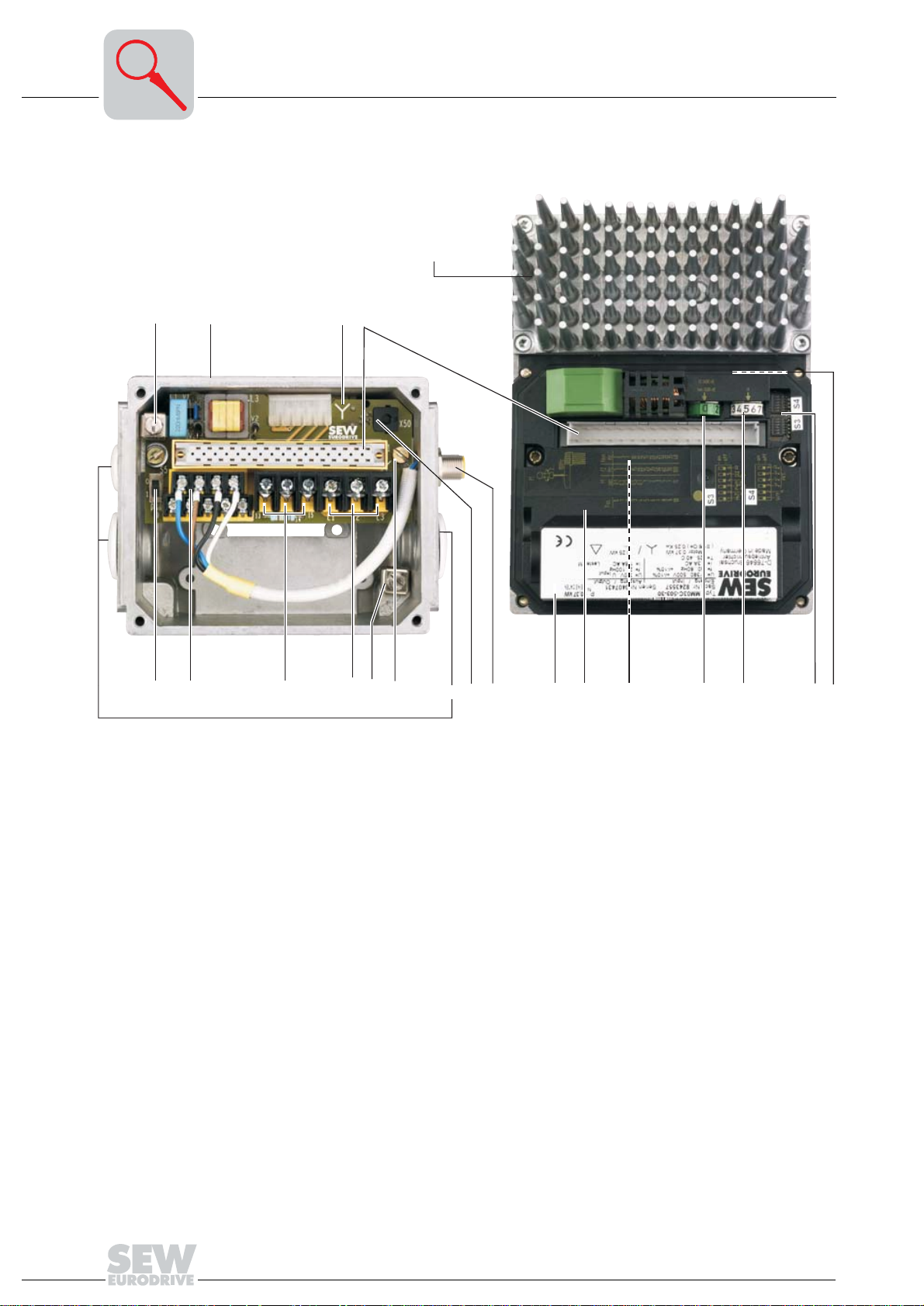
3.3 MOVIMOT® inverter (with integrated AS-Interface)
5
1
6
7
89
324
10
11
12
13
14
15 16 17 18
1. Screw for PE connection 댷
2. Terminal box (size 1 used as example)
3. Identification of the circuit type
4. Connection plug between connection unit and inverter
5. MOVIMOT
®
inverter with heat sink (size 1 used as example)
6. Switch S5 (AUX/24 V supply, for settings see the section "Startup")
7. Electronics terminal strip X2
8. Connection of brake coil (X3). For motors without brake: Connection of internal
braking resistor BW. (standard)
9. Mains connection L1, L2, L3 (X3) (suitable for 2 x 4 mm
10.Screw for PE connection
댷
2
)
11. Connection unit with terminals
12.Cable glands
13.Diagnostic interface (see the section "Diagnostics")
14.AS-i connection
15.Electronics nameplate
16.Safety hood for inverter electronics
17.Setpoint potentiometer f1 (not visible), accessible from top of MOVIMOT
®
inverter
via screw fitting
18.Setpoint switch f2 (green)
19.Switch t1 for generator ramp (white)
20.DIP switches S3 and S4 (for settings see the section "Startup")
21.Status LEDs (visible from top of MOVIMOT
®
inverter, see the section "Diagnostics")
19
20
06413AXX
21
12
Operating Instructions – MOVIMOT® MM03C - MM3XC
Page 13
Unit Design
Unit designations (MOVIMOT® with integrated AS-Interface)
3.4 Unit designations (MOVIMOT® with integrated AS-Interface)
Sample motor nameplate
3
SEW-EURODRIVE
KA77 DT90L4/BMG/MM15/RJ1A/AND3/AZSK
Typ
Nr.
3009818304. 0001. 99
KW
1,5/50HZ
50Hz
60Hz
r/min
Bremse
kg 73
Schmierstoff
KA 77 DT 90L4 BMG/MM15/RJ1A/AND3/AZSK
V 380-500
V 380-500
22/1400
V 230
Ma 665
Bruchsal / Germany
Nm 20
Nm
Made in Germany 184103 3.14
IEC 34
3~
IM
B3
0,99
cos
j
3,50
A
A
3,50
IP
Gleichrichter
i
Kl
54 F
64,75
:1
06488AXX
Plug connector for AS-i and sensor
connection
Plug connector for power
Terminal box design
MOVIMOT
Additional feature motor (brake)
®
frequency inverter
Size, motor pole count
Motor series
Gear unit size
Gear unit series
1) Detailed information about geared motor combinations can be found in the catalog "MOVIMOT® Geared
Motors."
1)
2)
Structure of sample fabrication number:
3009818304. 0001. 99
Final two digits of the year of manufacture
Running unit number (4 digits)
Order number (10 digits)
Operating Instructions – MOVIMOT® MM03C - MM3XC
13
Page 14
3
Unit Design
Unit designations (MOVIMOT® with integrated AS-Interface)
Sample inverter nameplate
MM 15 C – 503 – 30
52118AXX
Design
(30 = with integrated AS-Interface)
Connection type (3 = 3-phase)
Supply voltage
(50 = 380...500 V
Version C
AC
)
Device identification
Motor power (15 = 1.5 kW)
MOVIMOT
®
series
The device identification [1] at the top of the MOVIMOT® inverter contains information
about inverter type [2], inverter part number [3], equipment power [4] and adapted (associated) motors [5].
[2]
[3]
[5]
[1]
[4]
51967AXX
14
Operating Instructions – MOVIMOT® MM03C - MM3XC
Page 15
Unit Design
Unit designations (MOVIMOT® with integrated AS-Interface)
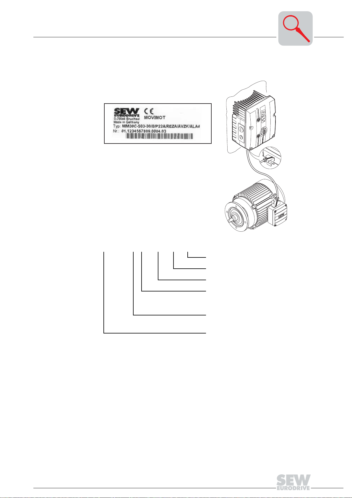
3
"Mounting close to the motor" design with option P2.A
The following illustration shows an example of the MOVIMOT® inverter with option P2.A
mounted close to the motor with corresponding nameplate and unit designation:
MM30C-503-30/0/P22A/REZA/A VSK/ALA4
52233AXX
Plug connector for connection to the motor
Plug connector option
Terminal box design
Adapter for mounting close to the motor
21 = Size 1
22 = Size 2
Circuit type
0 =
댴
1 = 쑶
MOVIMOT
®
Operating Instructions – MOVIMOT® MM03C - MM3XC
15
Page 16

4
Mechanical Installation
MOVIMOT® gearmotor
4 Mechanical Installation
4.1 MOVIMOT® gearmotor
Before you begin
Installation tolerances
Mounting
MOVIMOT
®
Install MOVIMOT® only if
• the entries on the nameplate of the drive match the voltage supply system,
• the drive is undamaged (no damage caused by transport or storage).
• it is certain that the following requirements have been fulfilled:
– Ambient temperature between –25 °C and +40 °C (remember that the tempera-
ture range of the gear unit may be restricted → operating instructions for the gear
unit)
– No oil, acid, gas, vapors, radiation, etc.
Shaft end Flanges
Diametric tolerance in accordance with DIN 748
• ISO k6 at ∅ ≤ 50 mm
•ISO m6 at ∅ > 50 mm
(Center bore in accordance with DIN 332, shape
DR)
Centering shoulder tolerance in accordance with
DIN 42948
•ISO j6 at ∅ ≤ 230 mm
• ISO h6 at ∅ > 230 mm
• The MOVIMOT® may only be mounted or installed in the specified mounting position
on a level, vibration-proof and torsionally rigid support structure.
• Thoroughly remove anti-corrosion agents from the shaft extensions (use a commercially available solvent). Do not allow the solvent to penetrate the bearings and shaft
seals – this could cause material damage!
• Carefully align MOVIMOT
®
and the driven machine, to avoid placing any unacceptable strain on the motor shafts (observe permissible overhung load and axial thrust
data!).
• Do not butt or hammer the shaft end.
• Use an appropriate cover to protect motors in vertical mounting positions from objects or fluids entering!
• Ensure an unobstructed cooling air supply and that air heated by other apparatus
cannot be drawn in or reused.
• Balance components for subsequent mounting on the shaft with a half key (output
shafts are balanced with a half key).
• Any condensation drain holes are closed with plastic plugs and must not be opened
unless needed.
• Do not leave any condensation drain holes open, since this defeats higher enclosure
ratings.
Installation in damp areas or in the open
16
• Use suitable screwed cable glands for the supply leads (use reducing adapters if
necessary).
• Coat the threads of cable glands and pocket caps with sealant and tighten them well
– then coat them again.
• Seal the cable entry well.
®
• Clean the sealing faces of the MOVIMOT
inverter well before re-assembly.
• Restore the anticorrosive coating if necessary.
• Check the type of enclosure is authorized (refer to the nameplate).
Operating Instructions – MOVIMOT® MM03C - MM3XC
Page 17
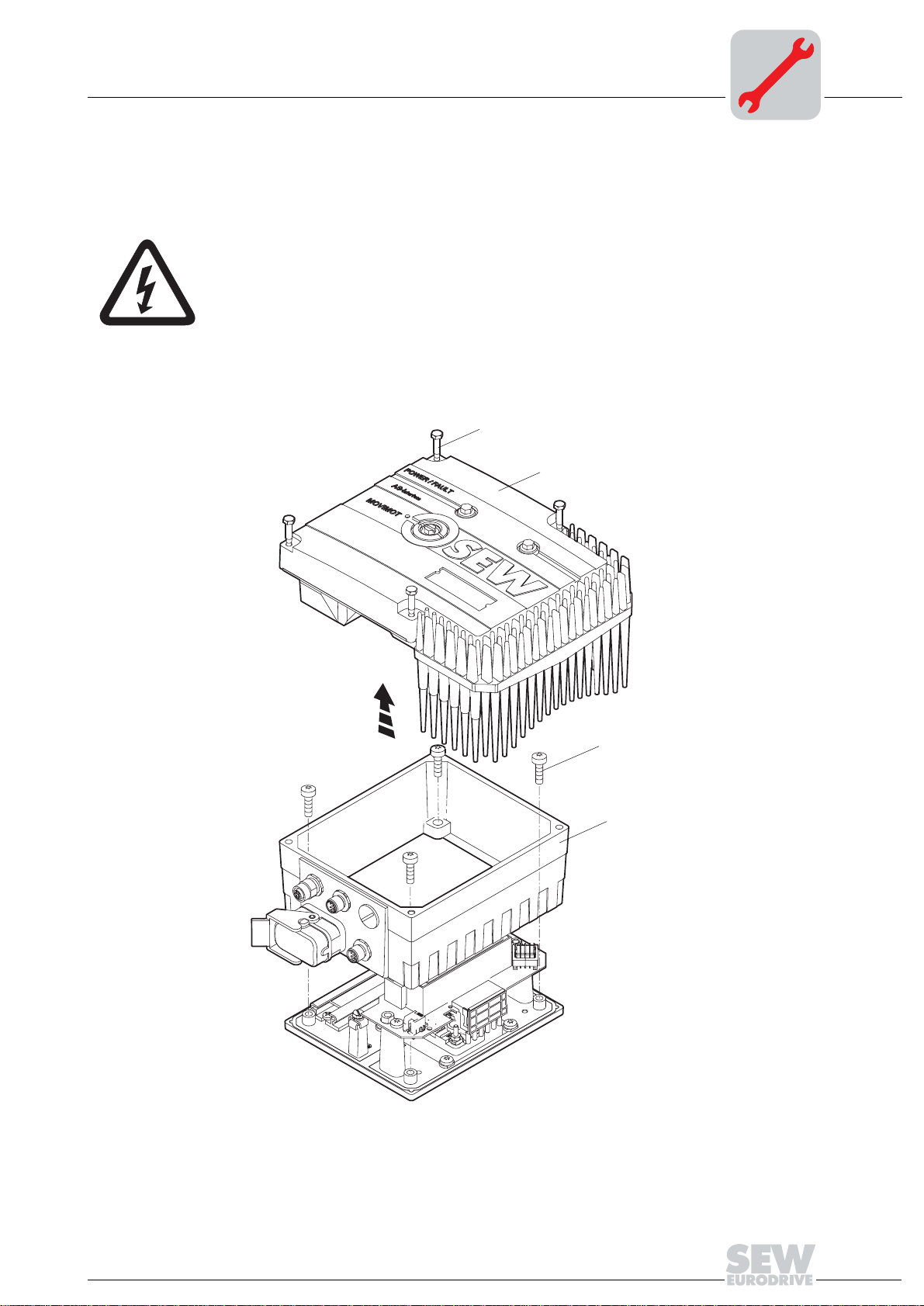
4.2 Modular terminal box
Mechanical Installation
Modular terminal box
4
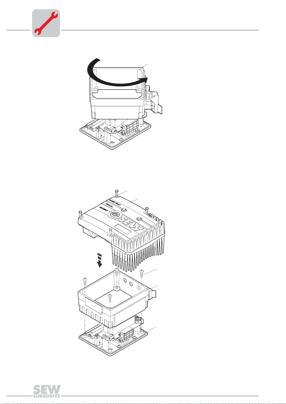
Turning the terminal box
In principle it is recommended to purchase factory pre-fabricated MOVIMOT® systems
with the correct position of cable entries. In exceptional cases, the position of the cable
entries can be turned to the opposite side (only for designs with modular terminal box).
1. Isolate MOVIMOT
restarting! Dangerous voltages may still be present for up to 1 minute after
shutdown!
2. Label the connections before disconnecting them for later reassembly.
3. Disconnect the supply system, control and sensor connections.
4. Remove screws [A] and detach MOVIMOT
5. Loosen screws [C] and remove terminal box [D].
®
drive from the supply, safeguarding it against unintentional
®
inverter [B].
[A]
[B]
[C]
[D]
51819AXX
Operating Instructions – MOVIMOT® MM03C - MM3XC
17
Page 18
4
Mechanical Installation
Modular terminal box
6. Turn terminal box [D] by 180°.
180˚
[D]
51820AXX
7. Place terminal box [D] on mounting plate [E] and fasten it with screws [C].
8. Reestablish cable connections.
9. Reattach MOVIMOT
®
inverter [B] and secure with screws [A].
[A]
[B]
18
[C]
[D]
[E]
51821AXX
Operating Instructions – MOVIMOT® MM03C - MM3XC
Page 19
Mechanical Installation
Mounting MOVIMOT® inverter with option P2.A close to the motor
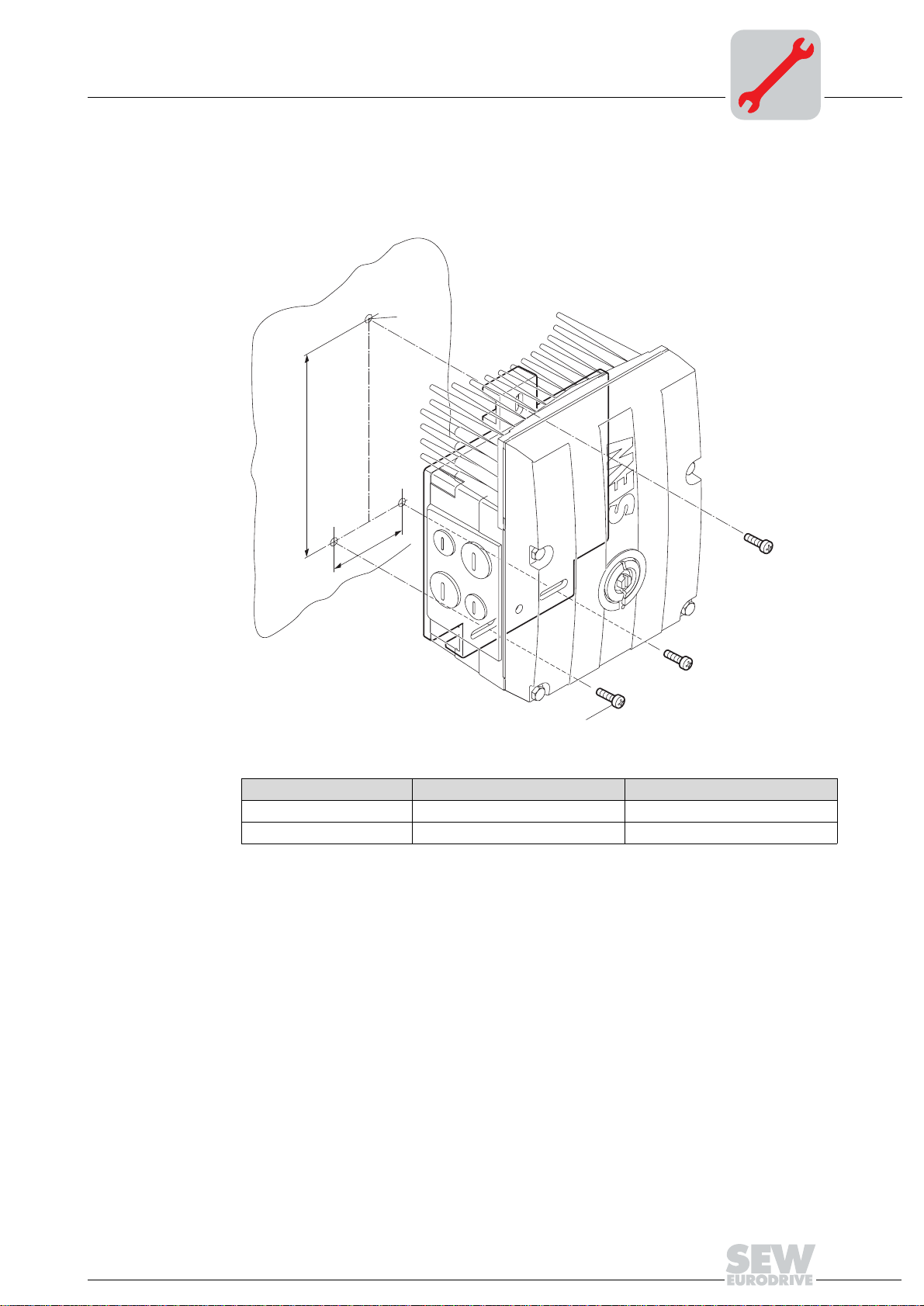
4.3 Mounting MOVIMOT® inverter with option P2.A close to the motor
4
The following illustration shows the mounting dimensions when mounting the
MOVIMOT
®
inverter with option P2.A close to the motor:
6
M
A
B
M6
Size A B
MM03 to MM15 65 mm 140 mm
MM22 to MM3X 65 mm 170 mm
51772AXX
Operating Instructions – MOVIMOT® MM03C - MM3XC
19
Page 20
4
Mechanical Installation
Option MLU..A / MLG..A / MLK11A
4.4 Option MLU..A / MLG..A / MLK11A
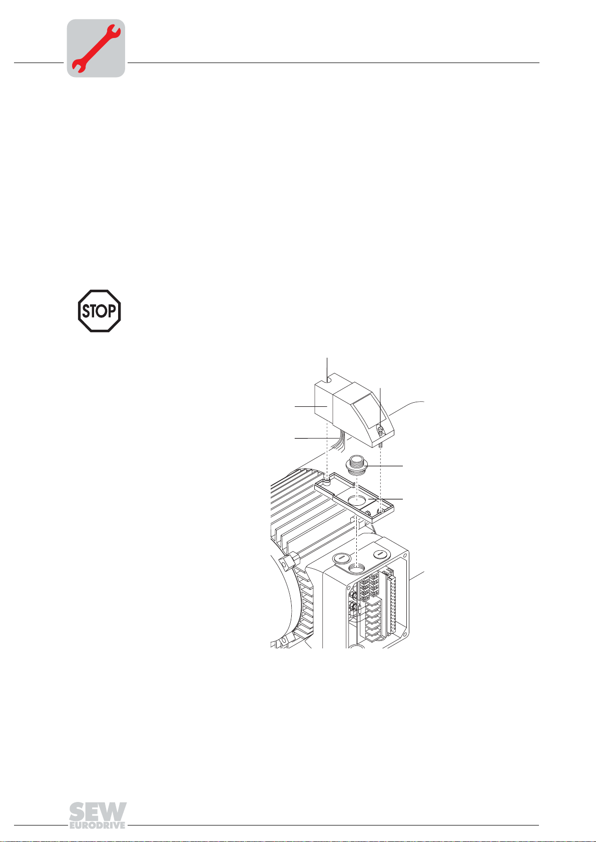
Scope of delivery
Installation
• MLU..A / MLG..A / MLK11A top [2]
•2 screws [1]
• Cable entry screw [4]
• MLU..A / MLG..A / MLK11A lower section [5]
1. Remove a screw plug from the MOVIMOT® terminal box.
2. Attach lower section [E] to MOVIMOT
®
terminal box and fasten it with cable entry
screw [4].
®
3. Guide connection cable [3] through cable entry screw [4] into the MOVIMOT
termi-
nal box.
4. Place top [2] on bottom [5] and fasten it with 2 screws [1].
Important: Option may be assembled only in the position shown in the following
figure!
[1]
[1]
[2]
[3]
[4]
[5]
05625AXX
20
Operating Instructions – MOVIMOT® MM03C - MM3XC
Page 21
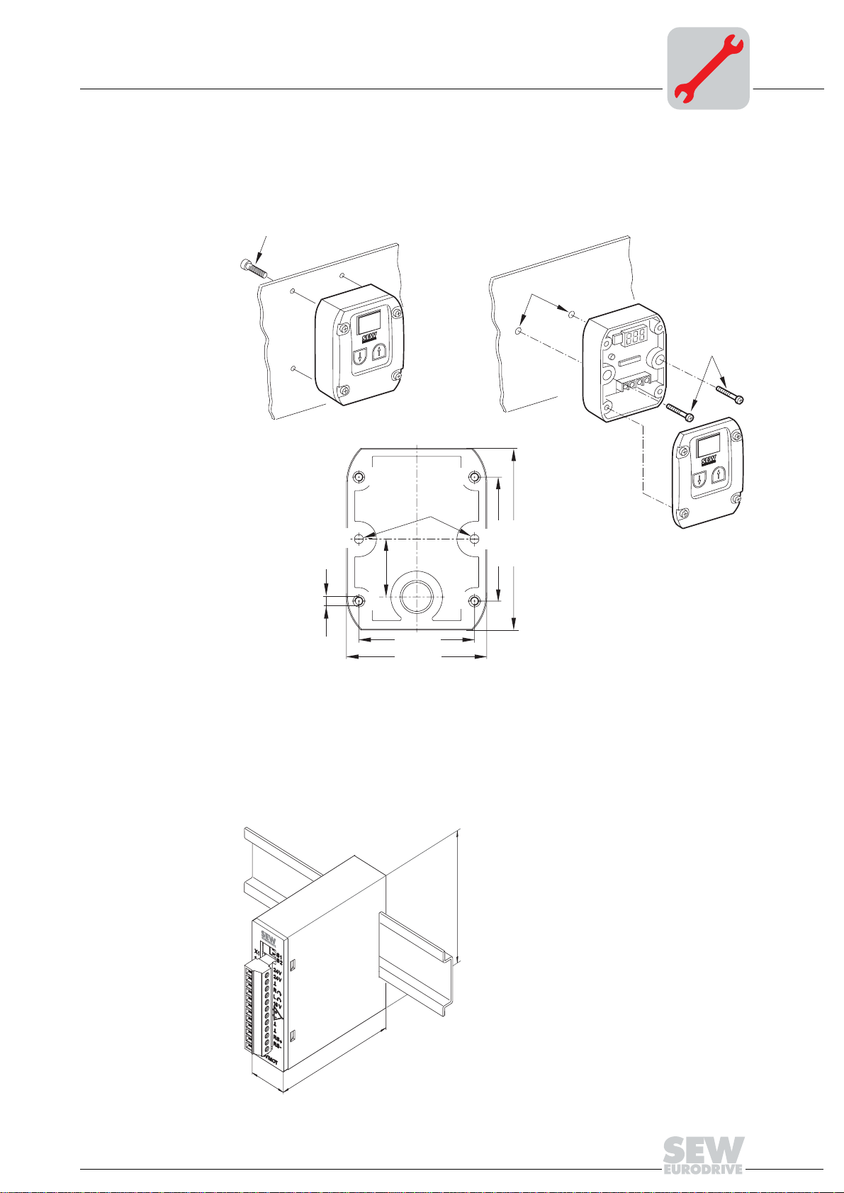
4.5 MBG11A option
• A: Assembly from the rear via 4 tapped holes
• B: Assembly from the front via 2 mounting holes
Mechanical Installation
MBG11A option
4
M4 x 5 + a
!!!!!A!!!!!!!!!!!!!!!!!!!!!!!!!!!!!!!!!!!!!!!!!!!!!!!!!!!!!!!B
M4
A
Ø 4,3 mm
A
B
m
m
60
m
m
88
M4
B
A
A
mm
8
2
56 mm
68 mm
M4 x 25
50520AXX
a = wall thickness
Screws are not included in the delivery!
4.6 MWA21A option
• MWA21A is installed in the switch cabinet on the DIN rail (DIN EN 50022):
75
74
22,5
50519AXX
Operating Instructions – MOVIMOT® MM03C - MM3XC
21
Page 22

4
4.7 URM option
Mechanical Installation
URM option
Mount the URM option with two screws according to the following illustration. Connection according to section "Electrical Installation."
The installation is only allowed in conjunction with modular terminal box!
52207AXX
22
Operating Instructions – MOVIMOT® MM03C - MM3XC
Page 23

Electrical Installation of MOVIMOT® Standard Design
Installation instructions
5 Electrical Installation of MOVIMOT® Standard Design
5.1 Installation instructions
5
Connecting supply system leads
• The rated voltage and frequency of MOVIMOT® must correspond to the data for the
power supply system (mains).
• Cable cross section: according to input current I
for rated power (see Technical
mains
Data).
• Permitted cable cross section of MOVIMOT
®
terminals (does not apply to field dis-
tributor)
Power terminals Control terminals
2
1.0 mm
AWG17 – AWG10 (2 x AWG10) AWG22 – AWG17 (2 x AWG18)
– 4.0 mm2 (2 x 4.0 mm2) 0.25 mm2 – 1.0 mm2 (2 x 0.75 mm2)
• Use conductor end sleeves without insulating shrouds (DIN 46228 part 1, material
E-CU).
• Install line safety at the beginning of the power cable behind supply bus junction (see
the section "Connection of MOVIMOT
®
basic unit," F11/F12/F13). Use D, DO, NH or
circuit breakers. The fusible rating should be selected in accordance with the cable
cross section.
• Do not use a conventional earth-leakage circuit breaker as a protective device. Universal current-sensitive earth leakage circuit-breakers (tripping current 300 mA) are
permitted as a protective device. During normal operation of MOVIMOT
®
, earth-leak-
age currents of > 3.5 mA can occur.
• Use contactor switch contacts to switch MOVIMOT
®
from utilization category AC-3
according to IEC 158.
• SEW recommends using earth-leakage monitors with pulse-code measurement for
voltage supply systems with non-grounded star point (IT nets). The use of such devices avoids mis-tripping of the earth-leakage monitor due to the earth capacitance
of the inverter.
Installation at 1000 meters above sea level (msl)
MOVIMOT® drives with supply voltages of 380 to 500 V can be used at altitudes above
2000 m MSL up to 4000 m MSL under the following peripheral conditions.
1)
• The rated continuous power is reduced based on the reduced cooling above 1000 m
(see the section "Technical Data and Dimension Drawings").
• Above 2000 msl, the air and creeping distances are only sufficient for overvoltage
class 2. If the installation requires overvoltage class 3, an additional external overvoltage protection must be used to ensure that overvoltage surges are limited to
2.5 kV phase-to-phase and phase-to-ground.
• If safe electrical separation is required, it must be implemented outside the device at
altitudes above 2000 m MSL (Safe Electrical Separation in accordance with
EN 50178).
• The permitted rated supply voltage of 3 x 500 V up to 2000 msl is reduced by 6 V for
every 100 m to a maximum of 3 x 380 V at 4000 msl.
1) The maximum altitude is limited by creeping distances and flameproof components such as electrolytic
capacitors.
Operating Instructions – MOVIMOT® MM03C - MM3XC
23
Page 24

5
Electrical Installation of MOVIMOT® Standard Design
Installation instructions
Connecting
24V
supply
DC
Conventional
control (via
binary commands)
Control via
RS-485 interface
Protection devices
UL compliant installation
• Supply MOVIMOT® either via external 24 VDC or via the MLU..A or MLG..A options.
• Connect the required control leads (e.g. CW/Stop, CCW/Stop, f1/f2 setpoint change)
• Use shielded cables as control leads and route them separately from power supply
cables.
with bus master PLC, MLG..A, MBG11A, MWA21A option or MF../MQ.. fieldbus interfaces
• Important: Connect only one bus master.
• Use twisted pair shielded cables as control leads and route them separately from
power supply cables.
•MOVIMOT® drives are equipped with integrated protective overload devices that are
making external overload devices obsolete.
• Only use copper cables with the temperature range 60/75 °C as connection lead:
• The permitted tightening torques for MOVIMOT
– 1.5 Nm (13.3 lb.in).
•MOVIMOT
(TN and TT systems) supplying a maximum supply current of 5000 A
a maximum rated voltage of 500 V
mance data of the fuses must not exceed 35 A/600 V.
• Only use tested units with a limited output voltage (V
current (I ≤ 8 A) as an external 24 V
• UL certification applies only to operation in voltage supply systems with voltages to
ground up to 300 V.
®
are suited for operation on voltage supply systems with grounded star
(MM03C-503 to MM3XC-503). The perfor-
AC
voltage source.
DC
®
power terminals are:
= 30 VDC) and limited output
max
and having
AC
24
Operating Instructions – MOVIMOT® MM03C - MM3XC
Page 25
Electrical Installation of MOVIMOT® Standard Design
Connection of MOVIMOT® basic unit
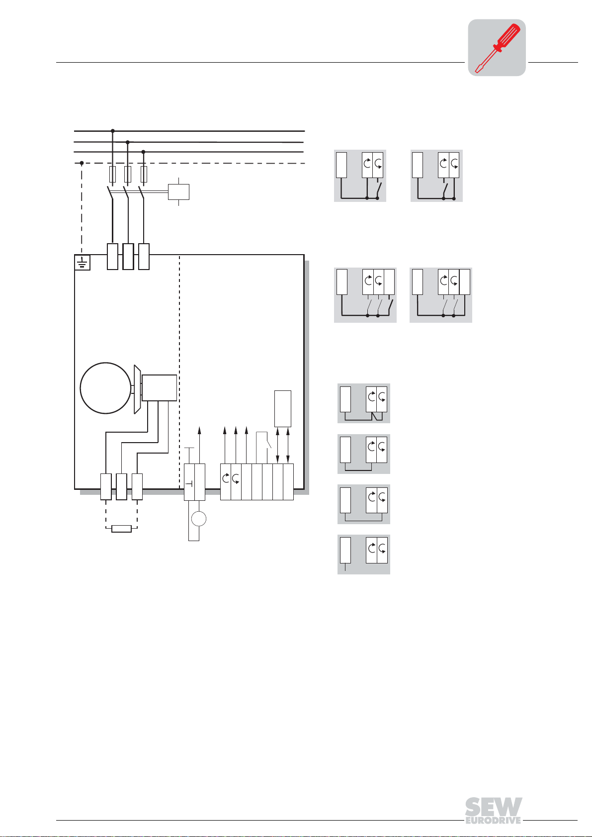
5.2 Connection of MOVIMOT® basic unit
5
L1
L2
L3
PE
M
3~
L1
F11/F12/F13
L2
L3
BMG
BMG
K11
[1]
MOVIMOT
MOVIMOT
[4]
[2]
[3]
[5]
®
®
RS-485
Function of terminals CW/Stop and CCW/Stop
with binary control:
24V
R
L
Rotation
CW active
Functions of terminals f1/f2:
24V
R
L
Setpoint f1 active Setpoint f2 active
Function of terminals CW/Stop and CCW/Stop
with control via RS-485 interface/fieldbus:
24V
R
L
24V
R
L
Rotation
CCW active
24V
R
f1/f2
Both directions of rotation
are enabled
L
f1/f2
K1
WH
14
13
BW.[6]
BL
15
=
24V
+
-
24 V
DC
L
R
f1/f2
K1a
K1b
RD
[1] 24 VDC supply (external or MLU../MLG.. option)
[2] CW/Stop
[3] CCW/Stop
[4] Setpoint toggle f1/f2
[5] Ready message (contact closed = ready for operation)
[6] BW.. braking resistor (in MOVIMOT
®
without mechanical brake only)
RS-
RS+
05614AXX
24V
24V
24V
Only CW rotation
R
R
R
is enabled,
L
Setpoint selections for CCW rotation
result in standstill of drive
Only CCW rotation
is enabled,
Setpoint selections for CW rotation
L
result in standstill
of drive
Drive is blocked or
L
brought to standstill
Operating Instructions – MOVIMOT® MM03C - MM3XC
25
Page 26
5
Electrical Installation of MOVIMOT® Standard Design
MOVIMOT® plug connectors
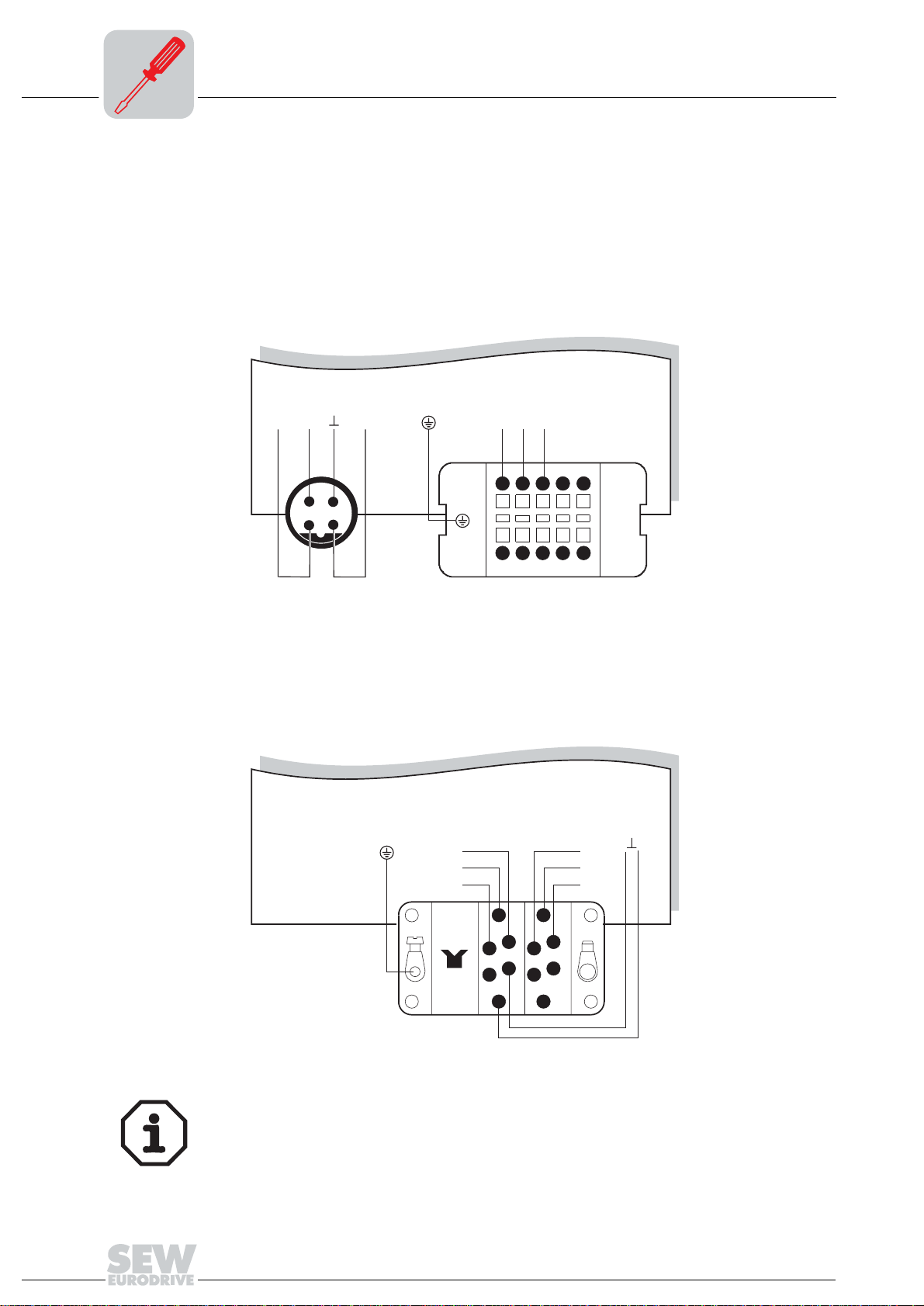
5.3 MOVIMOT® plug connectors
AVT1, ASA3 plug connectors
The following illustration shows the assignment of the optional AVT1 and ASA3 plug
connectors.
Available designs:
• MM.../ASA3
• MM.../AVT1
• MM.../ASA3/AVT1
®
52113AXX
24V RS+ RS-
4
3
12
AVT1
MOVIMOT
L1 L2 L3
12345
6789
ASA3
10
Plug connector AMA6
The following illustration shows the assignment of the optional AMA6 plug connector.
Available design:
• MM.../AMA6
MOVIMOT
RSRS+
24 V
C
1
3
5
6
AMA6
1
2
3
4
5
L3
L1
L2
A
2
4
6
®
52114AXX
For designs with plug connectors, both directions of rotation are enabled at the
factory. If only one direction of rotation is desired, please observe the section
"Connection of MOVIMOT
®
Basic Unit, Functions of the CW/STOP, CCW/STOP
terminals in control via RS-485 interface."
26
Operating Instructions – MOVIMOT® MM03C - MM3XC
Page 27
Electrical Installation of MOVIMOT® Standard Design
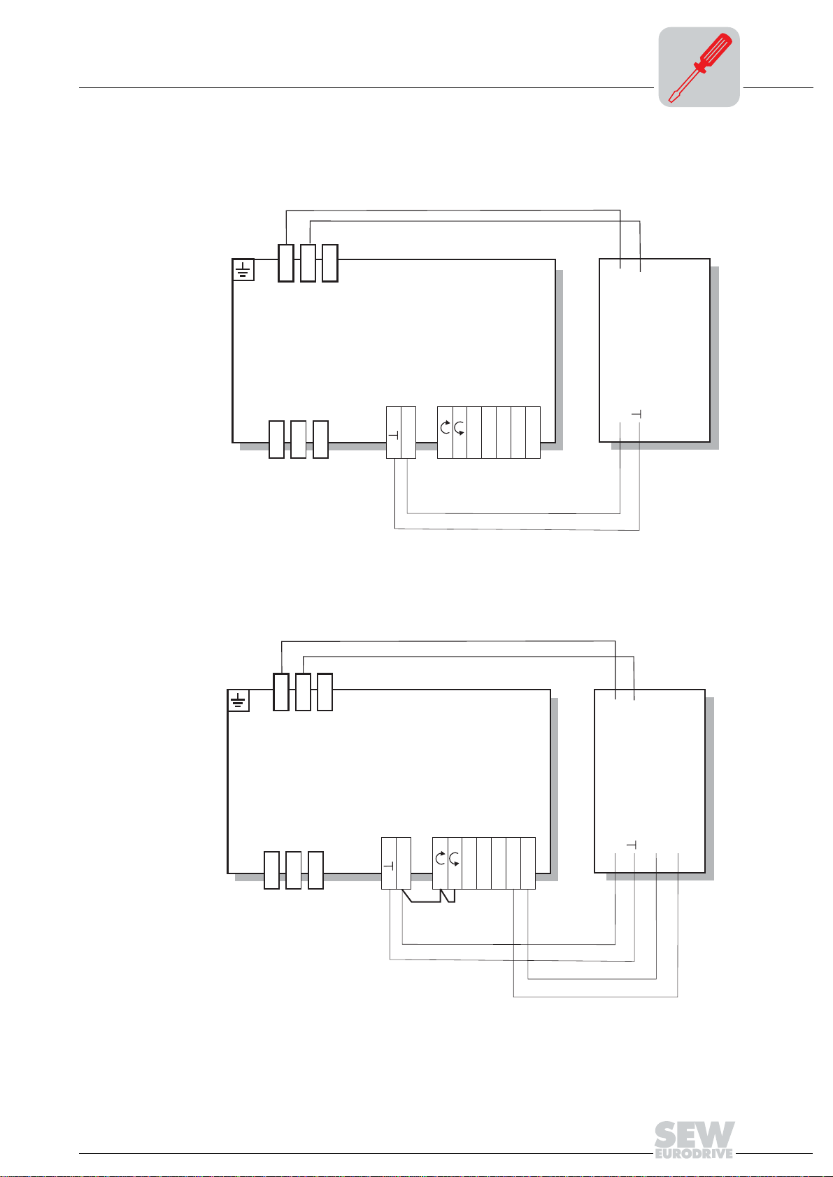
5.4 Connection MOVIMOT® options
Connection MOVIMOT® options
5
Connection of MLU11A option
The following figure shows the connection of the MLU11A option.
YE
YE
L1
L1
L2
L3
L2
13
13
14
14
15
15
L3
24V
24V
MOVIMOT
MOVIMOT
L
L
R
R
f1/f2
f1/f2
K1a
K1a
RD
BU
K1b
K1b
RS-
RS-
®
®
RS+
RS+
L1
L1
L2
L2
MLU11A
24V
24V
05651AXX
Connection of MLG11A option
The following figure shows the connection of the MLG11A option.
YE
YE
L1
L2
13
14
15
L3
24V
[1]
L
R
MOVIMOT
K1a
f1/f2
K1b
RS-
®
RS+
RD
L1
L2
MLG11A
24V
BU
RS+
OG
RS-
GN
[1] Observe the enabled direction of rotation (see the section "Connection of MOVIMOT®
basic unit, Functions of CW/Stop, CCW/Stop terminals with control via RS-485 interface.")
Operating Instructions – MOVIMOT® MM03C - MM3XC
05652AXX
27
Page 28
5
Electrical Installation of MOVIMOT® Standard Design
Connection MOVIMOT® options
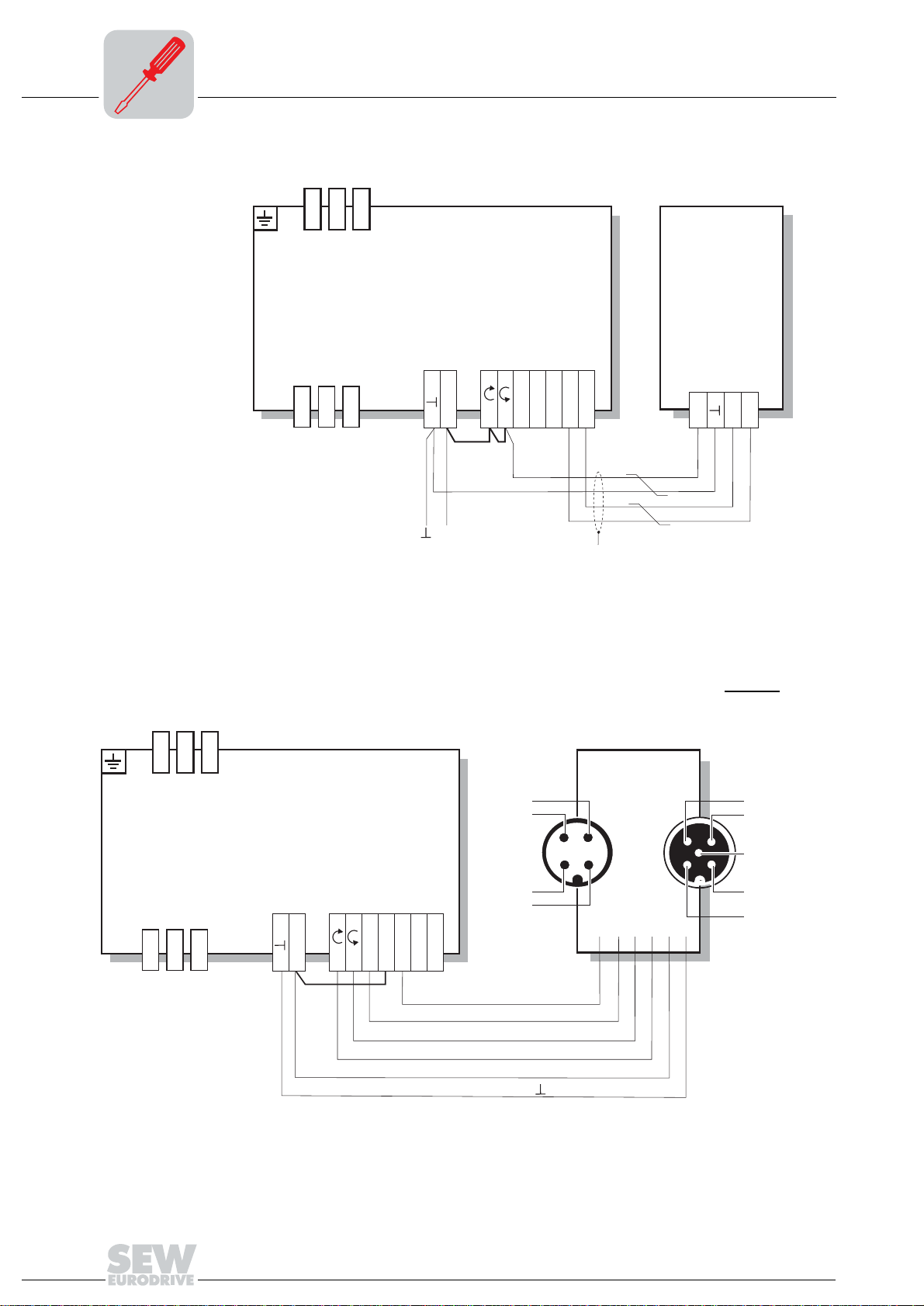
Connection of MBG11A option
The following figure shows the connection of the MBG11A option.
L1
L2
13
14
15
L3
24V
L
R
MOVIMOT
K1a
f1/f2
[1]
24 V
DC
[1] Observe the enabled direction of rotation (see the section "Connection of MOVIMOT®
basic unit, Functions of CW/Stop, CCW/Stop terminals with control via RS-485 interface.")
[2] EMC metal cable gland
K1b
[2]
RS-
®
RS+
댷
MBG11A
24V
RS+
RS-
03183CXX
Connection of MLK11A option
L1
14
13
L2
The following illustration shows the connection of the MLK11A option (external AS-i binary slave).
15
L3
24V
L
R
MOVIMOT
K1a
f1/f2
K1b
RS-
®
RS+
AS-i -
AS-i +
WH
BK/BU
BK/RD
BK/WH
RD
BU
N.C.
N.C.
[1]
(DI0)
(DO2)
(DO1)
(DO0)
(DO3)
()
MLK11A
[2]
0V
DI2
4
3
2
1
3
4
5
21
N.C.
24V
DI3
05118CXX
28
[1] AS-i connection
[2] Connection for two external sensors
Operating Instructions – MOVIMOT® MM03C - MM3XC
Page 29
Electrical Installation of MOVIMOT® Standard Design
Connection MOVIMOT® options
5
Connection of
The following figure shows the connection of the MWA21A option.
MWA21A option
L1
L2
13
14
15
L3
24V
L
R
MOVIMOT
K1a
f1/f2
[1]
[1] Note the released direction of rotation
(see the section "Connection of MOVIMOT® Basic Unit" Functions of CW/Stop,
CCW/Stop terminals with control via RS-485 interface)
[2] EMC metal cable gland
[3] Potentiometer with integration of 10 V reference voltage [A]
or potential-free analog signal [B]
K1b
RS-
®
RS+
댷
24V
DC
MWA21A
1 24V
2 24V
3
4 R
5 L
6 10V
[3]
댷
[2][2]
7 +
-
8
9
10
11 RS+
12 RS-
03184DXX
[A]
6 10V
7 +
8
9
10
6 10V
-
[B]
MWA21A
7 +
8
9
10
-
MWA21A
05622BXX
Operating Instructions – MOVIMOT® MM03C - MM3XC
29
Page 30
5
Electrical Installation of MOVIMOT® Standard Design
Connection MOVIMOT® options
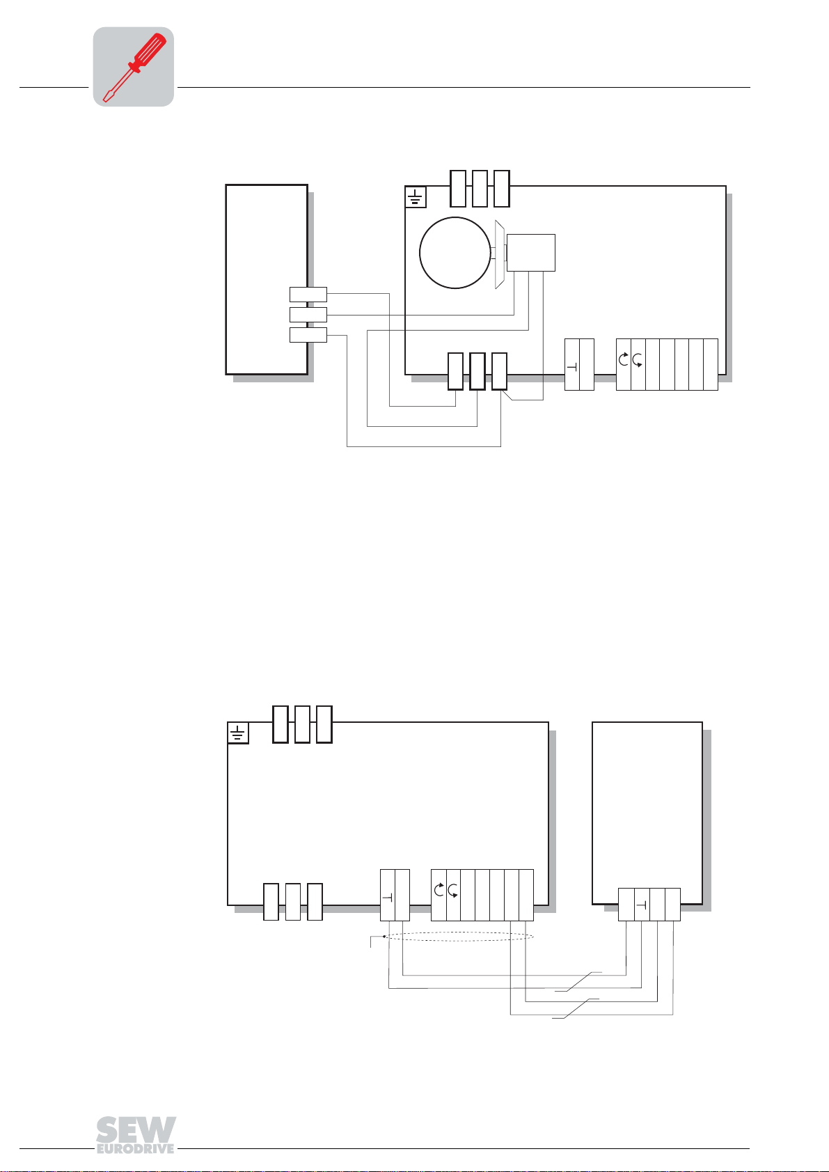
Connection of URM option
Connection of MDG11A option
The following figure shows the connection of the URM option.
URM
13
14
15
M
3~
RD
WH
13
14
L3
BMG
15
BU
24V
MOVIMOT
R
L
f1/f2
K1a
K1b
RS-
52203AXX
®
RS+
L1
L2
The following figure shows the connection of the MDG11A option.
• The diagnostic unit must be connected prior to the possible occurrence of a fault, as
MOVIMOT
®
error messages are not saved and the information is lost when the 24 V
supply is disconnected.
• Connecting the MDG11A to an RS-485 bus with several MOVIMOT
®
is not al-
lowed.
• The diagnostic unit can be used if the MOVIMOT
®
is controlled via terminals
(= address 0 [S1/1-S1/4 = OFF]).
• Do nut use the diagnostic unit if setpoint setting takes place via the RS-485 interface.
30
L1
L2
L3
R
14
13
[1] EMC metal cable gland
For operation see the section "Diagnostics"
15
[1]
24V
댷
Operating Instructions – MOVIMOT® MM03C - MM3XC
MOVIMOT
L
K1a
f1/f2
K1b
RS-
®
RS+
MDG11A
24V
RS+
RS-
03404CXX
Page 31

Electrical Installation of MOVIMOT® Standard Design
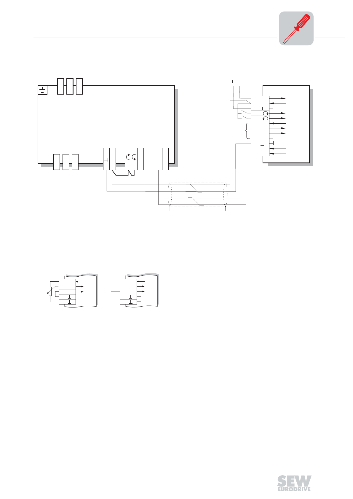
5.5 Connection RS-485 bus master
The following figure shows the connection of the RS-485 bus master.
L1
L2
L3
Connection RS-485 bus master
MOVIMOT
®
Busmaster
(SPS / PLC)
5
RS-485
14
13
[1] Observe enabled direction of rotation (see section "Connection of MOVIMOT® basic unit,
Functions of CW/Stop, CCW/Stop terminals with control via RS-485 interface.")
[2] EMC metal cable gland
[3] Potential compensation MOVIMOT
24 V
15
DC
24V
[1]
[3]
f1/f2
®
/RS-485 master
L
R
K1a
K1b
RS-
RS+
댷
RS-485
댷
[2][2]
03177BXX
Operating Instructions – MOVIMOT® MM03C - MM3XC
31
Page 32
5
Electrical Installation of MOVIMOT® Standard Design
Connection between MOVIMOT® and motor mounting close to the motor
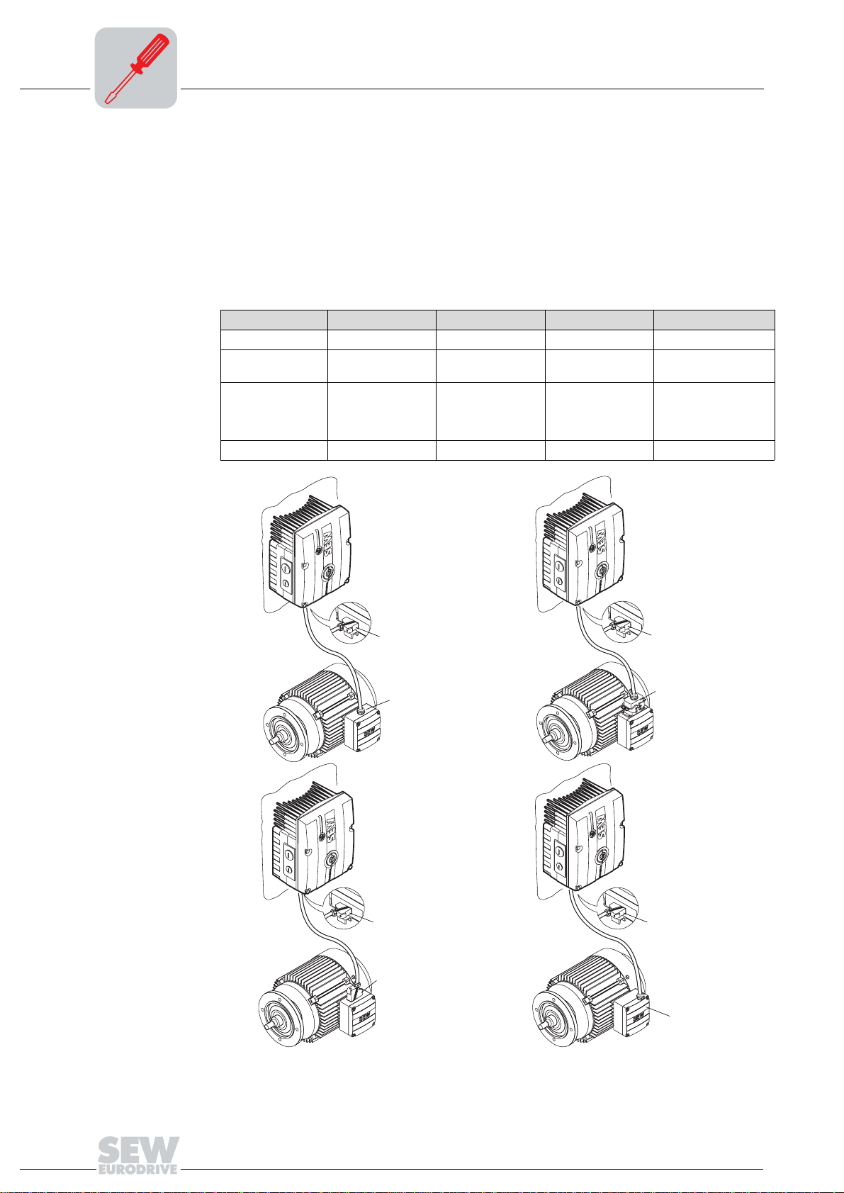
5.6 Connection between MOVIMOT® and motor mounting close to the motor
If the MOVIMOT® inverter with option P2.A is mounted close to the motor, the connection to the motor uses a pre-fabricated cable. The following designs are possible on the
MOVIMOT
• A: MM../P2.A/RO.A/APG4
• B: MM../P2.A/RE.A/ALA4
The APG 4 design results in the following connection options to the motor, dependent
upon the hybrid cable used:
Design A1 A2 A3 A4
MOVIMOT
Motor Cable gland/termi-
Hybrid cables 0 593 231 9 0 593 076 6 0 186 741 5 0816 325 1
See also... page 34 page 34 page 35 page 35
®
®
side:
APG4APG4APG4APG4
ASB4 APG4 IS
nals
0816 326 X 쑶
쑶
0593 278 5 댴
0593 755 8 댴
A1
A3
APG4
[1]
APG4
A2
APG4
ASB4
A4
APG4
32
APG4
IS
52198AXX
[1] Connection via terminals
Operating Instructions – MOVIMOT® MM03C - MM3XC
Page 33

Electrical Installation of MOVIMOT® Standard Design
Connection between MOVIMOT® and motor mounting close to the motor
The ALA 4 design results in the following connection options to the motor, dependent
upon the hybrid cable used:
Design B1 B2
MOVIMOT
Motor Cable gland/terminals ASB4
Hybrid cables 0 817 948 4 0 816 208 5
Additional
Information
®
ALA4 ALA4
page 36 page 36
5
B1
[1] Connection via terminals
[1]
ALA4
B2
ALA4
ASB4
52199AXX
Operating Instructions – MOVIMOT® MM03C - MM3XC
33
Page 34

5
Electrical Installation of MOVIMOT® Standard Design
Connection between MOVIMOT® and motor mounting close to the motor
Hybrid cable design A
• Design A1
Part number 0 593 231 9
52073AXX
The overall shield of the cable must be attached to the housing of the motor terminal box
using an EMC metal cable gland.
Cable assignment
Motor terminal Core color / designation
U1 Black / U1
V1 Black / V1
W1 Black / W1
13 Red / 13
14 White / 14
15 Blue / 15
TH Black / 1
TH Black / 2
PE terminal Green-yellow + shield end (inside shield)
• Design A2
Part number 0 593 076 6
52074AXX
34
Operating Instructions – MOVIMOT® MM03C - MM3XC
Page 35

Electrical Installation of MOVIMOT® Standard Design
Auftragsnummer:
R 01/00
Laenge (m):
593 278 5
Connection between MOVIMOT® and motor mounting close to the motor
• Design A3
Part number 0 186 741 5
• Design A4
52075AXX
R 01/00
Auftragsnummer:
593 278 5
Laenge (m):
52076AXX
5
Motor with IS lower part
Size DT71 – DT90
Motor with IS lower part
Size DV100
MOVIMOT® in star connection MOVIMOT® in delta connection
Hybrid cable part number
0593 278 5
Hybrid cable part number
0593 755 8
Hybrid cable part number
0816 325 1
Hybrid cable part number
0816 326 X
Operating Instructions – MOVIMOT® MM03C - MM3XC
35
Page 36

5
Electrical Installation of MOVIMOT® Standard Design
Connection between MOVIMOT® and motor mounting close to the motor
Hybrid cable design B
• B1 version
Part number 0 817 948 4
52077AXX
The overall shield of the cable must be attached to the housing of the motor terminal box
using an EMC metal cable gland.
Cable assignment
Motor terminal Core color / designation
U1 Black / U1
V1 Black / V1
W1 Black / W1
13 Red / 13
14 White / 14
15 Blue / 15
TH Black / 1
TH Black / 2
PE terminal Green-yellow + shield end (inside shield)
• B2 version
Part number 0 816 208 5
52078AXX
36
Operating Instructions – MOVIMOT® MM03C - MM3XC
Page 37

Electrical Installation with Integrated AS-Interface
Installation instructions
6 Electrical Installation with Integrated AS-Interface
6.1 Installation instructions
6
Connecting supply system leads
• The rated voltage and frequency of MOVIMOT® must correspond to the data for the
power supply system (mains).
• Cable cross section: according to input current I
for rated power (see Technical
mains
Data).
• Permitted cable cross section of MOVIMOT
®
terminals (does not apply to field dis-
tributor)
Power terminals Control terminals
2
1.0 mm
AWG17 – AWG10 (2 x AWG10) AWG22 – AWG17 (2 x AWG18)
– 4.0 mm2 (2 x 4.0 mm2) 0.25 mm2 – 1.0 mm2 (2 x 0.75 mm2)
• Use conductor end sleeves without insulating shrouds (DIN 46228 part 1, material
E-CU).
• Install line safety at the beginning of the power cable behind supply bus junction (see
the section "Connection of MOVIMOT
®
Basic Unit," F11/F12/F13). Use D, DO, NH
or circuit breakers. The fusible rating should be selected in accordance with the cable
cross section.
• Do not use a conventional earth-leakage circuit breaker as a protective device. Universal current-sensitive earth leakage circuit-breakers (tripping current 300 mA) are
permitted as a protective device. During normal operation of MOVIMOT
®
, earth-leak-
age currents of > 3.5 mA can occur.
• Use contactor switch contacts to switch MOVIMOT
®
from utilization category AC-3
according to IEC 158.
• SEW recommends using earth-leakage monitors with pulse-code measurement for
voltage supply systems with non-grounded star point (IT nets). The use of such devices avoids mis-tripping of the earth-leakage monitor due to the earth capacitance
of the inverter.
Installation at 1000 meters above sea level (msl)
MOVIMOT® drives with supply voltages of 380 to 500 V can be used at altitudes above
2000 m MSL up to 4000 m MSL under the following peripheral conditions.
1)
• The rated continuous power is reduced based on the reduced cooling above 1000 m
(see the section "Technical Data and Dimension Drawings").
• Above 2000 msl, the air and creeping distances are only sufficient for overvoltage
class 2. If the installation requires overvoltage class 3, an additional external overvoltage protection must be used to ensure that overvoltage surges are limited to
2.5 kV phase-to-phase and phase-to-ground.
• If safe electrical separation is required, it must be implemented outside the device at
altitudes above 2000 m MSL (Safe Electrical Separation in accordance with
EN 50178).
• The permitted rated supply voltage of 3 x 500 V up to 2000 msl is reduced by 6 V for
every 100 m to a maximum of 3 x 380 V at 4000 msl.
1) The maximum altitude is limited by creeping distances and flameproof components such as electrolytic
capacitors.
Operating Instructions – MOVIMOT® MM03C - MM3XC
37
Page 38

6
Electrical Installation with Integrated AS-Interface
Installation instructions
Protection devices
UL compliant installation
•MOVIMOT® drives are equipped with integrated protective overload devices that are
making external overload devices obsolete.
• Use only copper cables with the temperature range 60 / 75 °C.
• The permitted tightening torques for MOVIMOT
– 1.5 Nm (13.3 lb.in).
•MOVIMOT
(TN and TT systems) supplying a maximum supply current of 5000 A
a maximum rated voltage of 500 V
mance data of the fuses must not exceed 35 A/600 V.
• Only use tested units with a limited output voltage (V
current (I ≤ 8 A) as an external 24 V
• UL certification applies only to operation in voltage supply systems with voltages to
ground up to 300 V.
®
are suited for operation on voltage supply systems with grounded star
(MM03C-503 to MM3XC-503). The perfor-
AC
voltage source.
DC
®
power terminals are:
= 30 VDC) and limited output
max
and having
AC
38
Operating Instructions – MOVIMOT® MM03C - MM3XC
Page 39

Electrical Installation with Integrated AS-Interface
Connection options with integrated AS-Interface
6.2 Connection options with integrated AS-Interface
6
Mains and control
A Design with AVSK plug (1 x M12 connector):
Design A1 A2
Type designation MM../AVSK MM../AVSK
Switch S5 01
24 V supply Yellow AS-i cable Black AUX-PWR cable
AS-i connection Yellow AS-i cable Yellow AS-i cable (double tap)
Mains connection Terminals Terminals
Sensor connection Terminals Terminals
Additional
information
A1
[1]
page 42 page 42
A2
[1]
AS-i (YE)
(double tap)
AS-i (YE)
AUX-PWR
(BK)
52001AXX
[1] Mains
• The designs listed above are also valid for mounting the MOVIMOT® inverter with
option P2.A close to the motor.
Operating Instructions – MOVIMOT® MM03C - MM3XC
39
Page 40

6
Electrical Installation with Integrated AS-Interface
Connection options with integrated AS-Interface
B Design with AZSK plug (3 x M12 connector):
Design B1 B2 B3
Type designation MM../RC.A/AZSK MM../RC.A/AZSK MM../RC.A/AZSK
Switch S5 110
24 V supply Black AUX-PWR cable Black AUX-PWR cable
AS-i connection Yellow AS-i cable Yellow AS-i cable (double
Mains connection Terminals Terminals Terminals
Sensor connection M12 plug connector M12 plug connector M12 plug connector
Additional
information
page 43 page 43 page 43
(double tap)
tap)
Yellow AS-i cable
Yellow AS-i cable
B1
[1]
B3
[1]
2 x DI
2 x DI
AUX-PWR (BK)
AS-i (YE)
B2
[1]
2 x DI
AS-i (YE)
AUX-PWR
(BK)
40
AS-i (YE)
52002AXX
[1] Mains
• The designs listed above are also valid for mounting the MOVIMOT® inverter with
option P2.A close to the motor.
Operating Instructions – MOVIMOT® MM03C - MM3XC
Page 41
Electrical Installation with Integrated AS-Interface
Connection options with integrated AS-Interface
C Design with AND3/AZSK plug connector
(3 x M12 plug, 1 x Han Q8/0):
Design C1 C2 C3
Type designation MM../RJ.A/AND3/AZSK MM../RJ.A/AND3/AZSK MM../RJ.A/AND3/AZSK
Switch S5 110
24 V supply AUX-PWR cable AUX-PWR cable (double
AS-i connection Yellow AS-i cable Yellow AS-i cable (double
Mains connection AND3 plug connector AND3 plug connector AND3 plug connector
Sensor connection M12 plug connector M12 plug connector M12 plug connector
Additional
Information
page 44 page 44 page 44
tap)
tap)
Yellow AS-i cable
Yellow AS-i cable
6
C1
C3
2 x DI
AUX-PWR (BK)
AS-i (YE)
[1]
C2
2 x DI
[1]
AS-i (YE)
AUX-PW
(BK)
2 x DI
[1] Mains
• The designs listed above are also valid for mounting the MOVIMOT® inverter with
option P2.A close to the motor.
Operating Instructions – MOVIMOT® MM03C - MM3XC
AS-i (YE)
[1]
51761AXX
41
Page 42

6
Electrical Installation with Integrated AS-Interface
Connection of MOVIMOT® MM../AVSK (connection option A)
6.3 Connection of MOVIMOT® MM../AVSK (connection option A)
The following figure shows the connection of the MM../AVSK design.
L1
L2
L3
PE
L1
F11/F12/F13
L2
L3
K11
MM../AVSK
M
3~
WH
RD
13
BW.[7]
[1] 24 VDC supply
[2] AS-i data cable [3] AS-i data cable +
[4] Voltage supply for sensors
[5] Sensor DI2
[6] Sensor DI3
[7] BW.. braking resistor (in MOVIMOT
[8] M12 plug (yellow)
14
BL
15
BMG
BMG
[1]
[2]
[3]
[4]
[5]
VO
DI2
VO24
AS-I-
3
2
[8]
24V
AS-i -
AS-i +
4
3
2
1
®
without mechanical brake only)
[6]
DI3
24 V
4
1
AS-I+
51823AXX
42
Operating Instructions – MOVIMOT® MM03C - MM3XC
Page 43

Electrical Installation with Integrated AS-Interface
Connection of MOVIMOT® MM../AZSK (connection option B)
6.4 Connection of MOVIMOT® MM../AZSK (connection option B)
The following figure shows the connection of the MM../AZSK design.
L1
L2
L3
PE
L1
F11/F12/F13
L2
L3
K11
MM../AZSK
6
M
3~
WH
13
BW
BL
14
.
RD
AZSK plug connector
[1] M12 plug connector
(plug, black)
[2] M12 plug connector
(plug, yellow)
[3] M12 plug connector
(socket, black)
BMG
BMG
[1]
BK
4
3
2
15
1 24 V 24 V supply (AUX-PWR)
2 N.C. Not assigned
3 0 V AUX-PWR reference potential
4 N.C. Not assigned
1 AS-i + AS-i data cable +
2 0 V AUX-PWR reference potential
3 AS-i - AS-i data cable 4 24 V 24 V supply (AUX-PWR)
1 VO24 24 V voltage supply for sensors
2 DI3 Sensor input DI3
3VO⊥ 0 V reference potential for sensors
4 DI2 Sensor input DI2
1
3
4
2
24V
[2]
YE
4
1
AS-I -
3
2
1
3
2
24 V
4
1
AS-I+
BK
3
2
DI2
4
VO24
[3]
1
4
1
VO
3
2
DI3
52061AXX
Operating Instructions – MOVIMOT® MM03C - MM3XC
43
Page 44

6
V
Electrical Installation with Integrated AS-Interface
Connection of MOVIMOT® MM../AND3/AZSK (connection option C)
6.5 Connection of MOVIMOT® MM../AND3/AZSK (connection option C)
The following figure shows the connection of the MM../AND3/AZSK design.
24V 0
ASI+24V ASI-0V
4
4
3
3
2
2
1
1
3
3
4
4
1
1
2
2
[4]
PE
L1
N.C.
N.C.
L2
N.C.
[3]
PE
N.C.
N.C.
L3
[1]
4
4
3
3
[2]
2
2
1
1
0V
DI3 DI224V
AZSK plug connector
[1] M12 plug connector
(plug, black)
[2] M12 plug connector
(plug, yellow)
[4] M12 plug connector
(socket, black)
AND3 plug connector
[3] AND3 plug connector
(plug)
51940AXX
1 24 V 24 V supply (AUX-PWR)
2 N.C. Not assigned
3 0 V AUX-PWR reference potential
4 N.C. Not assigned
1 AS-i + AS-i data cable +
2 0 V AUX-PWR reference potential
3 AS-i - AS-i data cable 4 24 V 24 V supply (AUX-PWR)
1 VO24 24 V voltage supply for sensors
2 DI3 Sensor input DI3
3VO⊥ 0 V reference potential for sensors
4 DI2 Sensor input DI2
1 N.C. Not assigned (reserved for N)
2 L2 Mains connection L2
3 N.C. Not assigned
4 N.C. Not assigned
5 N.C. Not assigned
6 L3 Mains connection L3
7 N.C. Not assigned
8 L1 Mains connection L1
댷 PE PE
44
Operating Instructions – MOVIMOT® MM03C - MM3XC
Page 45

Electrical Installation with Integrated AS-Interface
6.6 Connection of URM option
The following figure shows the connection of the URM option.
URM
Connection of URM option
L1
L2
L3
MOVIMOT
6
®
13
14
15
M
3~
RD
WH
13
14
BMG
15
BU
24V
AS-i -
AS-i +
VO
DI2
VO24
DI3
52208AXX
Operating Instructions – MOVIMOT® MM03C - MM3XC
45
Page 46

6
Electrical Installation with Integrated AS-Interface
Connection between MOVIMOT® and motor mounting close to the motor
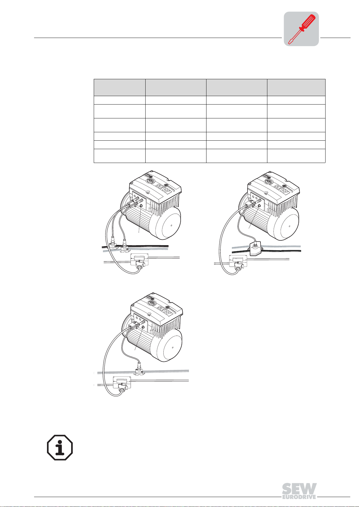
6.7 Connection between MOVIMOT® and motor mounting close to the motor
If the MOVIMOT® inverter with option P2.A is mounted close to the motor (only in conjunction with modular terminal box), the connection to the motor uses a pre-fabricated
cable. The following designs are possible on the MOVIMOT
• A: MM../P2.A/RO.A/APG4
• B: MM../P2.A/RE.A/ALA4
The APG4 design results in the following connection options to the motor, dependent
upon the hybrid cable used:
Design A1 A2 A3 A4
MOVIMOT
Motor Cable gland/termi-
Hybrid cables 0 593 231 9 0 593 076 6 0 186 741 5 0816 325 1
See also... page 48 page 48 page 49 page 49
®
APG4APG4APG4APG4
ASB4 APG4 IS
nals
®
side:
0816 326 X 쑶
쑶
0593 278 5 댴
0593 755 8 댴
A1
A3
APG4
[1]
APG4
A2
APG4
ASB4
A4
APG4
46
APG4
IS
51771AXX
[1] Connection via terminals
Operating Instructions – MOVIMOT® MM03C - MM3XC
Page 47

Electrical Installation with Integrated AS-Interface
Connection between MOVIMOT® and motor mounting close to the motor
The ALA4 design results in the following connection options to the motor, dependent
upon the hybrid cable used:
Design B1 B2
MOVIMOT
Motor Cable gland/terminals ASB4
Hybrid cables 0 817 948 4 0 816 208 5
Additional
Information
®
ALA4 ALA4
page 50 page 50
6
B1
[1] Connection via terminals
[1]
ALA4
B2
ALA4
ASB4
51853AXX
Operating Instructions – MOVIMOT® MM03C - MM3XC
47
Page 48

6
Electrical Installation with Integrated AS-Interface
Connection between MOVIMOT® and motor mounting close to the motor
Hybrid cable design A
• Design A1
Part number 0 593 231 9
52073AXX
The overall shield of the cable must be attached to the housing of the motor terminal box
using an EMC metal cable gland.
Cable assignment
Motor terminal Core color / designation
U1 Black / U1
V1 Black / V1
W1 Black / W1
13 Red / 13
14 White / 14
15 Blue / 15
TH Black / 1
TH Black / 2
PE terminal Green-yellow + shield end (inside shield)
• Design A2
Part number 0 593 076 6
52074AXX
48
Operating Instructions – MOVIMOT® MM03C - MM3XC
Page 49

Electrical Installation with Integrated AS-Interface
Auftragsnummer:
R 01/00
Laenge (m):
593 278 5
Connection between MOVIMOT® and motor mounting close to the motor
• Design A3
Part number 0 186 741 5
• Design A4
52075AXX
R 01/00
Auftragsnummer:
593 278 5
Laenge (m):
52076AXX
6
Motor with IS lower part
Size DT71 – DT90
Motor with IS lower part
Size DV100
MOVIMOT® in star connection MOVIMOT® in delta connection
Hybrid cable part number
0593 278 5
Hybrid cable part number
0593 755 8
Hybrid cable part number
0816 325 1
Hybrid cable part number
0816 326 X
Operating Instructions – MOVIMOT® MM03C - MM3XC
49
Page 50

6
Electrical Installation with Integrated AS-Interface
Connection between MOVIMOT® and motor mounting close to the motor
Hybrid cable design B
• B1 version
Part number 0 817 948 4
52077AXX
The overall shield of the cable must be attached to the housing of the motor terminal box
using an EMC metal cable gland.
Cable assignment
Motor terminal Core color / designation
U1 Black / U1
V1 Black / V1
W1 Black / W1
13 Red / 13
14 White / 14
15 Blue / 15
TH Black / 1
TH Black / 2
PE terminal Green-yellow + shield end (inside shield)
• B2 version
Part number 0 816 208 5
52078AXX
50
Operating Instructions – MOVIMOT® MM03C - MM3XC
Page 51

7 Startup of Standard Design
7.1 Important startup instructions
• It is essential to comply with the safety notes during installation!
• Before removing/attaching the MOVIMOT
from the power supply system (mains). Dangerous voltages may still be
present for up to 1 minute after shutdown.
• Ensure before startup that the drive has not been damaged.
• Check that all protective covers are installed correctly.
• Use "CW/Stop" or "CCW/Stop" for jog mode.
• A minimum switch-off time of 2 seconds must be maintained for the mains contactor
K11.
7.2 Description of the controls
Startup of Standard Design
Important startup instructions
®
inverter, it must be disconnected
I
7
00
Setpoint potentiometer f1
Setpoint switch f2
3
4
5
6
7
8
The potentiometer has a different function, depending on the unit operating mode:
• Control via terminals: Setpoint f1 (selected by tl. f1/f2 = "0")
• Control via RS-485: Maximum frequency f
100
f [Hz
]
75
50
25
2
123456789100
[1] Pot. position
6
5
max
[1]
f
1
05066BXX
The function of the switch changes depending on the unit operating mode:
• Control via terminals: Setpoint f2 (selected by tl. f1/f2 = "1")
• Control via RS-485: Minimum frequency f
Switch f2
Detent position 0 12345678910
Setpoint f2 [Hz] 5 7 1015202535506070100
Mini. frequency [Hz] 2 5 7 10 12 15 20 25 30 35 40
min
Switch t1
3
4
5
6
7
8
Operating Instructions – MOVIMOT® MM03C - MM3XC
For integrator ramp (ramp times based on a setpoint jump of 50 Hz)
Switch t1
Detent position 012345 678910
Ramp time t1 [s] 0.1 0.2 0.3 0.5 0.7 1 235710
51
Page 52

7
DIP switches S1 and S2
I
Startup of Standard Design
Description of the controls
00
50522AXX
DIP switch S1:
S1 1 2 3 4 5
Message RS-485 address
2021222
ON 1111 Off
OFF 0 0 0 0 On adapted 4 kHz Off
Motor
3
protec-
tion
6
Motor
rating class
Motor one
size smaller
7
PWM
frequency
Variable
(16, 8, 4 kHz)
8
No-load
damping
On
DIP switch S2:
S2 1 2 3 4 5 6 7 8
Message Motor
ON
OFF IEC motor Off VFC Off 0 0 0 0
1) only available in Brazil
type
SEW DZ
motor:
1)
Brake release
without
Enable
On V/f On
Control pro-
cess
Speed
monitoring
Selection of options
2021222
1111
3
52
Operating Instructions – MOVIMOT® MM03C - MM3XC
Page 53

Description of the DIP switches S1
7.3 Description of the DIP switches S1
Startup of Standard Design
I
7
00
DIP switches
S1/1-S1/4
Selection of RS-485 address of MOVIMOT® via binary coding
Decimal
Address
S1/1 – X – X – X – X – X – X – X – X
S1/2 ––
S1/3 ––––
S1/4 ––––––––
X = ON
–= OFF
Depending on the control of MOVIMOT
Control RS-485 address
Binary control (terminal operation) 0
Via external AS-i binary slave (MLK11A) 0
Via keypad (MLG.., MBG..) 1
Via fieldbus interface (MF..) 1
Via fieldbus interface with integrated small control system (MQ..) 1 to 15
Via RS-485 master 1 to 15
0 1 2 3 4 5 6 7 8 9 10 11 12 13 14 15
X X ––X X ––X X ––X X
X X X X ––––X X X X
X X X X X X X X
®
, different addresses must be set:
DIP switches
S1/5
Motor protection activated or deactivated
• If the MOVIMOT
®
inverter is mounted close to the motor (with option P2.A or in the
field distributor), the motor protection must be deactivated.
• To ensure motor protection after all, a TH (bimetallic thermostat) must be used. In
this case, the TH opens the sensor circuit after reaching the nominal response temperature (see the "Startup with field distributor" section in the "Drive System for Decentralized Installation" system manual).
Operating Instructions – MOVIMOT® MM03C - MM3XC
53
Page 54

7
I
Startup of Standard Design
Description of the DIP switches S1
00
DIP switches
S1/6
Motor rating class smaller
• If it is activated, the DIP switch enables the assignment of MOVIMOT
®
to a motor
with a smaller rating class. The rated power of the unit remains unchanged.
• If a motor with less power is used, the overload capacity of the drive may increase
since the motor considers the MOVIMOT
®
to be one power increment too high. A
larger current may be impressed for a short period of time, which results in higher
torques.
• The purpose of switch S1/6 is the short-term utilization of the motor peak torque. The
current limit of the respective unit is always the same, independent of the switch setting. The motor protection function is adapted in reference to the switch setting.
• In this operating mode with S1/6 = "ON", a pull-out protection of the motor is
not possible.
MOVIMOT®
inverter
S1/6 = OFF S1/6 = ON
Assigned motor
댴 쑶 댴 쑶
MM03 DT71D4 DR63L4
MM05 DT80K4 DT71D4 DT71D4 DFR63L4
MM07 DT80N4 DT80K4 DT80K4 DT71D4
MM11 DT90S4 DT80N4 DT80N4 DT80K4
MM15 DT90L4 DT90S4 DT90S4 DT80N4
MM22 DV100M4 DT90L4 DT90L4 DT90S4
MM30 DV100L4 DV100M4 DV100M4 DT90L4
MM3X – DV100L4 DV100L4 DV100M4
1) Only possible with offset assembly
1)
DR63L4
1)
–
1)
DIP switches
S1/7
DIP switches
S1/8
Setting the maximum PWM frequency
• With setting DIP SWITCH S1/7 = OFF, MOVIMOT
®
operates with 4 kHz PWM fre-
quency.
• With setting DIP SWITCH S1/7 = ON, MOVIMOT
®
operates with a 16 kHz PWM frequency (low noise) and switches back in steps to lower switching frequencies depending on the heat sink temperature.
No-load damping function (S1/8 = ON)
Upon activation, the function prevents resonant oscillations in no-load operation.
54
Operating Instructions – MOVIMOT® MM03C - MM3XC
Page 55

Description of the DIP switches S2
7.4 Description of the DIP switches S2
Startup of Standard Design
I
7
00
DIP switches
S2/1
DIP switches
S2/2
Operation with
braking resistor
Function with terminal control
(address = 0)
Motor type
• With IEC and NEMA motors, DIP switch S2/1 must always be set to OFF!
• With DZ motor with rated voltages of 220/380 V, 60 Hz (only available in Brazil), the
DIP switch must always be set to ON.
Releasing the brake without enable
With activated switch S2/2 = "ON", the brake can also be released if no drive enable is
present.
The special function is not in effect if operated with braking resistor.
With terminal control, the brake can be released by setting terminal f1/f2 if the following
requirements exist:
Terminal condition
R L f1/f2
"1"
"0"
"0"
"1"
"1"
"0"
"0"
"1"
"1"
"1"
"0"
"0"
"1" "1" "1" Unit not
"0" "0" "1" Unit not
All conditions possible
Enable condition Fault condi-
"0" Unit enabled No
"1" Unit enabled No
"0" Unit not
enabled
enabled
enabled
Unit not
enabled
tion
Unit fault
Unit fault
No
Unit fault
No
Unit fault
No
Unit fault
Unit fault Brake closed
Brake function
Brake is controlled by MOVIMOT
setpoint f1
Brake is controlled by MOVIMOT
setpoint f2
Brake closed
Brake closed
Brake released for manual procedure
®
,
®
,
Functions in bus
In bus operation, the brake is released through control in the control word.
operation
Master
PO1
PI1
PO = Process output data PI = Process input data
PO1 = Control word PI1 = Status word 1
PO2 = Speed (%) PI2 = Output current
PO3 = Ramp PI3 = Status word 2
DO = Digital outputs DI = Digital inputs
Operating Instructions – MOVIMOT® MM03C - MM3XC
PO2
PI2
PO
PI
PO3
PI3
DO
DI
MOVIMOT
+
-
®
52117AXX
55
Page 56

7
I
Startup of Standard Design
Description of the DIP switches S2
00
Setting bit 8 in the control word allows the brake to be released under the following conditions:
Basic control block
15 14 13 12 11 10 9
Control word
Not assigned
Enable
condition
Unit
enabled
Unit
enabled
Unit not
enabled
Unit not
enabled
Unit not
enabled
Fault condition Status of bit 8 in con-
No unit fault /
no communications timeout
No unit fault /
no communications timeout
No unit fault /
no communications timeout
No unit fault /
no communications timeout
Unit fault /
communications timeout
876543210
Bit
"8"
trol word
"0" Brake is controlled by
"1" Brake is controlled by
"0" Brake closed
"1" Brake released for man-
"1" or "0" Brake closed
"1" =
Reset
Virtual terminals for releasing the brake without
drive enable
Not assigned
Brake function
MOVIMOT
MOVIMOT
ual procedure
"1 1 0" = Release
otherwise stop
®
®
In case of a unit fault / communications timeout, the brake cannot be released via
special function.
Setpoint selection
in terminal operation
Behavior with a
non-operating unit
LED display
Setpoint selection in terminal operation depends on status of terminal f1/f2:
Enable condition Terminal f1/f2 Active setpoint
Unit enabled Terminal f1/f2 = "0" Setpoint potentiometer f1 active
Unit enabled Terminal f1/f2 = "1" Setpoint potentiometer f2 active
In case of a non-operating unit, the brake is always applied independent of the setting
of terminal f1/f2 or bit 8 in the control word.
The yellow LED display flashes periodically and quickly (ton : t
= 100 ms : 300 ms) if
off
the brake was released for manual procedure. This applies to terminal operation as well
as bus operation.
56
Operating Instructions – MOVIMOT® MM03C - MM3XC
Page 57

Startup of Standard Design
Description of the DIP switches S2
I
7
00
DIP switches
S2/3
DIP switches
S2/4
DIP switches
S2/5 to S2/8
Control process
• DIP switches S2/3 = OFF: VFC operation for 4-pole motors
• DIP switches S2/3 = ON: U/f operation reserved for special cases
Speed monitoring
• Speed monitoring (S2/4 = "ON" is used for the protection of the drive during blocking.
• If the drive is operated at the current limit for more than 1 second with active speed
monitoring (S2/4 = "ON"), the speed monitoring trips. MOVIMOT
®
signals a fault via
status LED (red, flashing slowly, fault code 08). The current limit must be attained uninterruptedly for the duration of the delay time before the monitoring function responds.
Selection of options
• Special functions can be selected using the binary coding of the DIP switches.
• The possible values can be set as follows:
Decimal
Value
S2/5 –
S2/6 ––
S2/7 ––––
S2/8 ––––––––
0 1 2 3 4 5 6 7 8 9 10 11 12 13 14 15
X – X – X – X – X – X – X – X
X X ––X X ––X X ––X X
X X X X ––––X X X X
X X X X X X X X
X = ON
–= OFF
• An overview of the selectable special functions can be found on page 58.
Operating Instructions – MOVIMOT® MM03C - MM3XC
57
Page 58

I
7
Startup of Standard Design
Selectable special functions MM..C-503-00
00
7.5 Selectable special functions MM..C-503-00
Overview of
selectable special
functions
Decimal
Value
0 Basic functionality, no special function selected X X – –
1 MOVIMOT
2 MOVIMOT
3 MOVIMOT
4 MOVIMOT
5 MOVIMOT
6 MOVIMOT
7 MOVIMOT
8 MOVIMOT
9 MOVIMOT
10 MOVIMOT
11 Monitoring of supply phase fault is deactivated
12 MOVIMOT
13 to 15 Not assigned – – – –
Brief description Intended oper-
®
with increased ramp times
®
(fault if exceeded)
(switchable via terminal f1/f2)
quency
reduced torque at low frequencies
tection via TH
with adjustable current limitation
®
with adjustable current limitation
®
with bus parameter setting
®
with motor protection via TH
®
with maximum 8 kHz PWM fre-
®
with rapid start / stop
®
with minimum frequency 0 Hz
®
for hoist applications
®
with minimum frequency 0 Hz and
®
with quick start/stop and motor pro-
ating mode
Bus Termi-
nals
XX
XX
XX
X–
X–
XX
XX
XX
XX
XX
XX
XX
see
Replaces
page
MOVIMOT
type
page 59MM..B-503-01
page 59MM..B-503-02
page 60MM..B-503-05
page 62–
page 64MM..B-503-14
(partially)
page 65MM..B-503-13
page 66–
page 68–
page 69–
page 71–
page 71–
page 72–
®
B
58
Operating Instructions – MOVIMOT® MM03C - MM3XC
Page 59

Startup of Standard Design
6
7
85
6
7
85
Selectable special functions MM..C-503-00
I
7
00
Special function 1
Function description
Changed ramp
times
3
4
5
6
7
8
MOVIMOT® with increased ramp times
S2
ON
1
3
2
4
6
85
7
05592AXX
• It is possible to set ramp times up to 40 s.
• If 3 process data words are used in bus operation, a ramp time of up to 40 s can be
transmitted.
Switch t1
Detent position 0123456 7 8 9 10
Ramp time t1 [s] 0.1 0.2 0.3 0.5 0.7 1
= Corresponds to standard setting
= Changed ramp times
20 25 30 35 40
Special function 2
Function description
Adjustable current
limits
3
4
5
6
7
8
MOVIMOT® with adjustable current limitation (fault if exceeded)
S2
ON
1
3
2
4
6
85
7
05596AXX
• The current limit can be set via switch f2.
• The setpoint f2 (with control via terminals) or the minimum frequency (with control via
RS-485) can no longer be changed and is fixed at the following values:
– Setpoint f2: 5 Hz
– Minimum frequency: 2 Hz
• Monitoring becomes effective above 15 Hz. If the drive is operated at the current limit
for more than 500 ms, the unit changes to the fault status (fault 44). The status is indicated through rapid red flashing.
Switch f2
Detent position 012345678910
I
max
[%] of I
N
90 95 100 105 110 115 120 130 140 150 160
Operating Instructions – MOVIMOT® MM03C - MM3XC
59
Page 60

7
6
7
85
I
Startup of Standard Design
Selectable special functions MM..C-503-00
00
Special function 3
Function description
Response after
reaching the current limitation
In-system values
for setpoint f2/minimum frequency
MOVIMOT® with adjustable current limitation (switchable via terminal f1/f2), with
reduction of frequency if exceeded
S2
ON
1
3
2
4
6
85
7
05598AXX
The current limitation can be set via switch f2. The binary input terminal f1/f2 can be
used to toggle between maximum current limit and the current limitation set via switch f2.
• After reaching the current limit, the unit reduces the frequency using the current limitation function and if necessary stops the ramp to prevent the current from increasing.
• If the unit operates at the current limitation, the status is displayed through rapid
green flashing of the status LED.
• It is no longer possible to toggle via terminals between setpoint f1 and setpoint f2 in
terminal operation or to set the minimum frequency in bus operation.
• The minimum frequency in bus operation is fixed at 2 Hz.
Adjustable current
limits
3
4
5
6
7
8
Selection of current limits via
binary input terminal f1/f2
Switch f2
Detent position 012345678910
I
max
[%] of I
24V
24V
N
R
L
f1/f2
03819AXX
R
L
f1/f2
03820AXX
60 70 80 90 100 110 120 130 140 150 160
f1/f2 = "0" 160 % current limitation is active
f1/f2 = "1" The current limitation set via switch f2 is active.
The selection can also be made with enabled unit.
60
Operating Instructions – MOVIMOT® MM03C - MM3XC
Page 61

Startup of Standard Design
Selectable special functions MM..C-503-00
I
7
00
Influencing the current characteristic
curve
By selecting a lower current limit, the calculation of the current limit is carried out with a
constant factor.
Motor with star connection
max
/ I
n
[%]
I
200
160
100
50
[1]
[2]
0
50
100
f [Hz]
50851AXX
[1] Current limit characteristic curve of standard function
[2] Reduced current limit for special function 3 and terminals f1/f2 = "1"
Motor with delta connection
I
max
/ In [%]
200
160
100
50
[1]
[2]
0
50
10087
f [Hz]
50852AXX
[1] Current limit characteristic curve of standard function
[2] Reduced current limit for special function 3 and terminals f1/f2 = "1"
Operating Instructions – MOVIMOT® MM03C - MM3XC
61
Page 62

7
6
7
85
I
Startup of Standard Design
Selectable special functions MM..C-503-00
00
Special function 4
Function description
MOVIMOT® with bus parameter setting
S2
ON
1
3
2
4
6
85
7
05599AXX
The function is implemented exclusively with bus operation via fieldbus interfaces MQ.. with integrated small control.
A parameter channel is available to operate the unit, and the values are saved in
EEPROM.
Read the following SEW-EURODRIVE manuals for additional information:
• DeviceNet/CANopen Interfaces, Field Distributors
• InterBus Interfaces, Field Distributors
• PROFIBUS Interfaces, Field Distributors
Potentiometer f1 and switches f2 and t1 are deactivated. The settings of the potentiometer and the switches are ignored by MOVIMOT
®
. The setting of the DIP switches continues to be read in by the unit. Functions selected via DIP switches cannot be changed
using the bus.
Block diagram
[1]
PC +
MOVITOOLS
P ROF I
PROCESSFIELD BUS
U S
B
UWS21A
®
[2]
MOVIMOT
MQ..
RS-485
50853AXX
62
[1] Fieldbus
[2] Diagnostic interface
Operating Instructions – MOVIMOT® MM03C - MM3XC
Page 63

Startup of Standard Design
Selectable special functions MM..C-503-00
I
7
00
Changing the
parameters in
MOVITOOLS
Open MOVITOOLS®/Shell as follows
®
• Select "MOVIMOT
®
" equipment class [1]
• Under program execution, select "Shell" [2]
[1]
[2]
05595AEN
After opening MOVITOOLS
®
/Shell, the following parameters are accessible. They can
be changed and stored in the unit.
Name Area Index Parameter
Ramp up 0.1...1...2000 [s] 8807 130 0.1 s – 1 s: 0,01
Ramp down 0.1...1...2000 [s] 8808 131
Minimum frequency 2...100 [Hz] 8899 305 0.1
Maximum frequency
Current limit 60...160 [%] 8518 303 1
Pre-magnetization time 0...0.4...2 [s] 8526 323 0.001
Post-magnetization time 0...0.1...2 [s] 8585 732 0.001
Parameter lock On/Off 8595 803 –
Factory setting Yes/No 8594 802 –
Delay time (P501/503)
Speed monitoring
Brake release time 0..2 [s] 8749 731 0.001
Slip compensation
Factory setting = bold
1) Example: Maximum frequency = 60 Hz
2) If the special function setting is changed, the value is set to the rated motor slip.
1)
2)
Bus setpoint = 10 %
Frequency setpoint = 6 Hz
2...100 [Hz] 8900 306 0.1
0.1...1...10.0 [s] 8558 501 0.1
0..500 [1/min] 8527 324 0.2
number
Step width
1 s – 10 s: 0,1
10 s – 100 s: 1
100 s – 2000 s: 10
• The factory setting is activated as soon as special function 4 is activated via DIP
switches. If the selected special function via DIP switches remains unchanged after
switching off the 24 V operating voltage, the reactivation will use the last known values from EEPROM.
• The start frequency is fixed at 0.5 Hz, the stop frequency at 3 Hz.
• If the set setpoint or the maximum frequency is lower than the set minimum frequen-
cy, the minimum frequency becomes active.
• The indexes are only evaluated with this special function.
Operating Instructions – MOVIMOT® MM03C - MM3XC
63
Page 64

7
6
7
85
I
Startup of Standard Design
Selectable special functions MM..C-503-00
00
Special function 5
Function description
MOVIMOT® motor protection via TH
S2
ON
1
3
2
4
6
85
7
05600AXX
The special function is only intended for bus operation in conjunction with mounting of the MOVIMOT
®
inverter close to the motor (with option P2.A or in the field
distributor).
Functions in connection with fieldbus interfaces MF.. and MQ..:
• If both direction of rotation terminals are opened, special function 5 generates fault
84 (overtemperature motor).
• In conjunction with the mounting of the MOVIMOT
®
inverter close to the motor (with
option P2.A or in the field distributor), the direction of rotation terminals are set to "0"
by the TH in case of overtemperature in the motor.
• Fault 84 is displayed by means of a flashing signal of the status LED at MOVIMOT
®
• The generated fault 84 is also transmitted via fieldbus.
.
Functions in connection with fieldbus interfaces MQ..:
•MOVIMOT
®
bus parameter setting according to special function 4 (see page 62).
Functions in connection with fieldbus interfaces MF..:
• Potentiometer f1 and switches f2 and t1 are deactivated and the following values
apply:
Name Value
Ramp up 1 [s]
Ramp down 1 [s]
Minimum frequency 2 [Hz]
Maximum frequency 100 [Hz]
Current limit 160 [%]
Pre-magnetization time 0.4 [s]
Post-magnetization time 0.1 [s]
Delay time speed monitoring 1 [s]
Brake release time 0 [s]
Slip compensation Rated motor slip
64
Operating Instructions – MOVIMOT® MM03C - MM3XC
Page 65

Startup of Standard Design
6
7
85
Selectable special functions MM..C-503-00
I
7
00
Tripping conditions for fault 84
Fault 84 "Overtemperature Motor" is tripped if all of the following requirements are met:
• The standard MOVIMOT
®
motor protection function can be deactivated via DIP
switch S1/5 = ON.
• The direction of rotation terminals are wired to 24 V via a TH as shown in the following figure.
With field distributor:
L
R
TH
24V
TH
52119AXX
With mounting on motor
with option P2.A:
L
24V
TH
R
52120AXX
• The TH tripped due to excessive temperature of the motor (release of both direction
of rotation terminals does not apply).
• Mains voltage is present.
If only the 24 VDC supply voltage is present at the MOVIMOT®, the fault is not initiated.
Special function 6
Function description
MOVIMOT® with maximum 8 kHz PWM frequency
S2
ON
1
3
2
4
6
85
7
05601AXX
• The special function reduces the maximum adjustable PWM frequency via S1/7 from
16 kHz to 8 kHz.
• When DIP switch S1/7 = "ON", the unit operates with an 8 kHz PWM frequency (low
noise) and switches back to 4 kHz depending on the heat sink temperature.
without
ON
OFF PWM frequency 4 kHz PWM frequency 4 kHz
PWM frequency variable
16, 8, 4 kHz
with
PWM frequency variable
S1/7
special function 6
S1/7
special function 6
8, 4 kHz
Operating Instructions – MOVIMOT® MM03C - MM3XC
65
Page 66

7
6
7
85
I
Startup of Standard Design
Selectable special functions MM..C-503-00
00
Special function 7
Function description
MOVIMOT® with rapid start/stop
S2
ON
1
3
2
4
6
85
7
05602AXX
• The pre-magnetization time is fixed at 0 s, independent of whether MOVIMOT® is
operated in bus or terminal mode.
• No pre-magnetization is carried out at the start of the release to begin the acceleration at the setpoint ramp as quickly as possible.
• The subsequent behavior of MOVIMOT
®
is dependent on the operating mode and
whether a mechanical brake is connected.
Special function 7
Rapid start/stop
Operating mode
Mechanical brake controlled by...
Relay function Ready relay
...MOVIMOT
®
Bus opera-
tion
...relay out-
put
Brake relay
(see page
75)
...MOVIMOT
Ready relay
®
Terminal
operation
...relay out-
put
Brake relay
(see page
75)
66
Operating Instructions – MOVIMOT® MM03C - MM3XC
Page 67

Startup of Standard Design
Selectable special functions MM..C-503-00
I
7
00
Bus operation
Mechanical brake controlled by MOVIMOT®:
• Terminals 13, 14 and 15 are assigned to the brake coil of the mechanical brake at
the wiring board of MOVIMOT
®
.
• The new function "Brake applied at down ramp" is introduced. Bit 9 in the control
word is assigned with this function as virtual terminal according to MOVILINK
®
pro-
file.
• As soon as bit 9 is set during the down ramp, MOVIMOT
®
applies the brake and in-
hibits the output stage.
• If the motor frequency is lower than the stop frequency, the brake is applied independent of the status of bit 9.
• The relay is switched as ready relay (standard function).
Mechanical brake controlled by relay output:
• A braking resistor (BW..) must be connected to terminal 13 and 15 at the wiring board
of MOVIMOT
®
, terminal 14 is not assigned.
• The relay functions as brake control relay so that the ready signal function is no longer available (it is imperative that you observe section "Use of relay output with special
function 7 + 9" starting on page 75).
• The new function "Brake applied at down ramp" is introduced. Bit 9 in the control
word is assigned with this function as virtual terminal according to MOVILINK
®
pro-
file.
• As soon as bit 9 is set during the down ramp, the relay output applies the brake and
MOVIMOT
®
inhibits the output stage.
• If the motor frequency is lower than the stop frequency, the brake is applied independent of the status of bit 9.
"Brake control in bus operation" flowchart:
1
[1]
0
[2]
n
1
[3]
0
1
[4]
0
[1] Enable terminals/control word
[2] Speed
[3] Bit 9
[4] Brake control signal: 1 = open, 0 = closed
t
t
t
t
05319BXX
Operating Instructions – MOVIMOT® MM03C - MM3XC
67
Page 68

7
6
7
85
I
Startup of Standard Design
Selectable special functions MM..C-503-00
00
Terminal operation
Special function 8
Mechanical brake controlled by MOVIMOT
®
• Terminals 13, 14 and 15 are assigned to the brake coil of the mechanical brake at
the wiring board of MOVIMOT
®
.
• The mechanical brake cannot be influenced by the terminals. The brake works analogous to a unit without special function.
• The relay is switched as ready relay (standard function).
Mechanical brake controlled by relay output
• A braking resistor (BW..) must be connected to terminal 13 and 15 at the wiring board
of MOVIMOT
®
, terminal 14 is not assigned.
• The relay functions as brake control relay so that the ready signal function is no longer available (it is imperative that you observe section "Use of relay output with special
function 7 + 9" starting on page 75).
Important: The rapid stop function cannot be used in terminal operation!
MOVIMOT® with minimum frequency 0 Hz
Function description
3
4
5
6
7
8
S2
ON
1
3
2
4
6
85
7
05603AXX
Control via RS-485:
If switch f2 is in position of rest 0, the minimum frequency measures 0 Hz with activated
special function. All other adjustable values remain unchanged.
Switch f2
Detent position 0 12345678910
Minimum frequency [Hz]
with activated special function
Minimum frequency [Hz]
without special function
0 5 7 10 12 15 20 25 30 35 40
2 5 7 10 12 15 20 25 30 35 40
Control via terminals:
If switch f2 is in position of rest 0, the setpoint f2 measures 0 Hz with activated special
function. All other adjustable values remain unchanged.
68
3
4
5
6
7
8
Switch f2
Detent position 0 12345678910
Setpoint f2 [Hz]
with activated special function
Setpoint f2 [Hz]
without special function
0 7 10 15 20 25 35 50 60 70 100
5 7 1015202535506070100
Operating Instructions – MOVIMOT® MM03C - MM3XC
Page 69
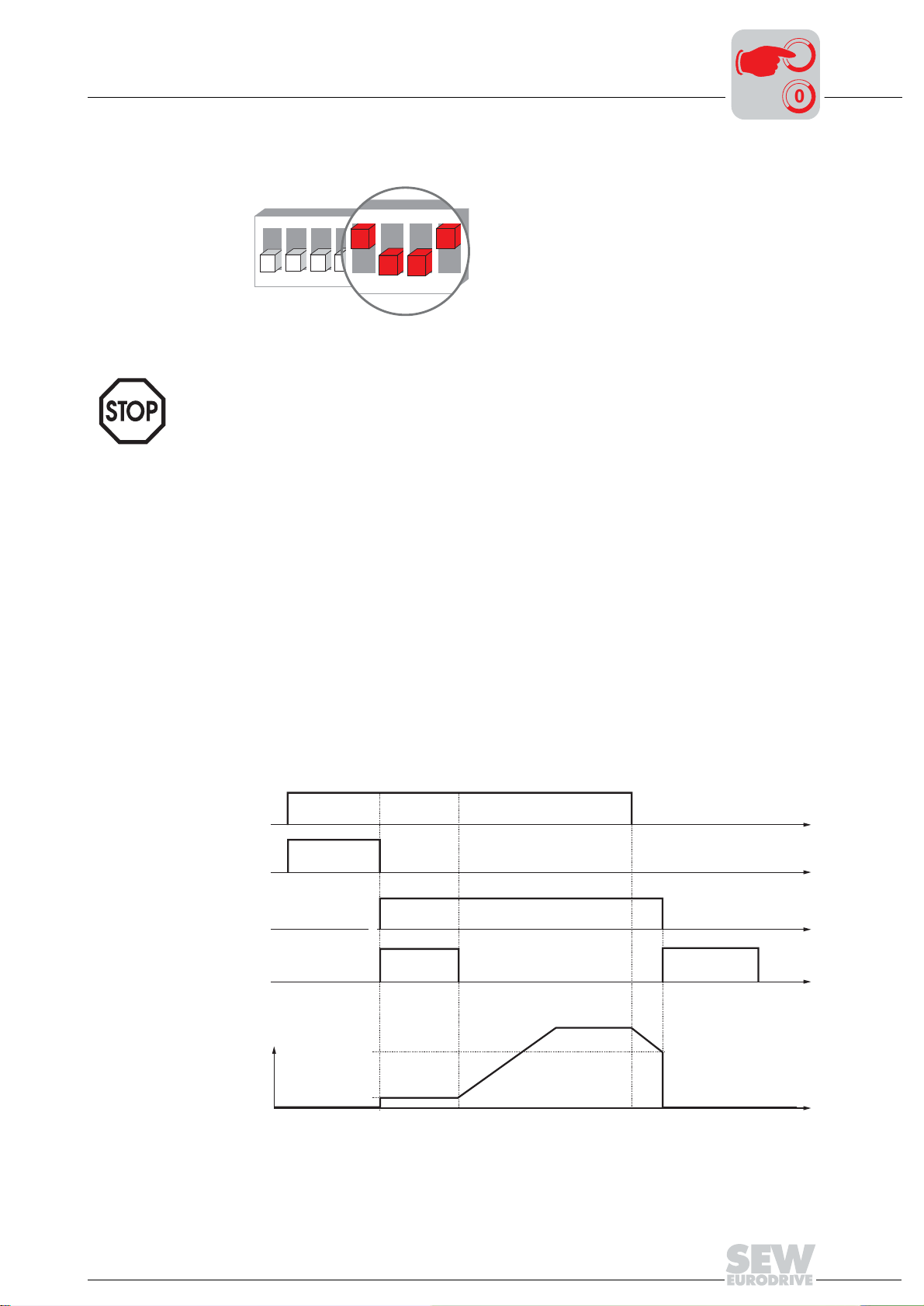
Startup of Standard Design
6
7
85
Selectable special functions MM..C-503-00
I
7
00
Special function 9
Pre-requisites
Function description
MOVIMOT® for hoist applications
S2
ON
1
3
2
4
6
85
7
05604AXX
MOVIMOT® may only be used in hoist applications if the following pre-requisites
are met:
• Special function 9 is only possible in connection with brake motors.
• Ensure that VFC operation (DIP switches S2/3 = OFF) is selected.
• The use of brake control BGM in connection with an external braking resistor is imperative (starting on page 75).
• It is recommended to activate the function "Speed monitoring" (page 57) .
• The start frequency is 2 Hz with terminal and bus operation. If the function is not activated, the start frequency is 0.5 Hz.
• The brake release time is fixed at 200 ms (standard = 0 ms), which prevents the motor from working against the applied brake.
• The brake reaction time (post-magnetization time) is 150 ms (standard = 100 ms),
which ensures that the brake is applied as soon as the motor stops generating
torque.
• The subsequent behavior of MOVIMOT
®
is dependent on the operating mode (see
page 70).
Overview of brake control with special function 9:
[1]
[2]
1
[3]
0
200 ms
[4]
[6]
[1] Enable
[2] Pre-magnetization time
[3] Brake control signal
[7]
3Hz
[8]
2Hz
1 = open, 0 = closed
[4] Brake release time
[5] Brake reaction time
(Post-magnetization time)
t
t
t
150 ms
[5]
[6] Frequency
[7] Stop frequency
[8] Start/minimum frequency
t
05613AXX
Operating Instructions – MOVIMOT® MM03C - MM3XC
69
Page 70

7
I
Startup of Standard Design
Selectable special functions MM..C-503-00
00
Bus operation
• The mechanical brake is controlled by the relay output.
• A braking resistor (BW..) must be connected to terminal 13 and 15 at the wiring board
of MOVIMOT
®
, terminal 14 is not assigned.
• The relay functions as brake control relay so that the ready signal function is no longer available (it is imperative that you observe section "Use of relay output with special
function 7 + 9" starting on page 75).
• The new function "Brake applied at down ramp" is introduced. Bit 9 in the control
word is assigned with this function as virtual terminal according to MOVILINK
®
pro-
file.
• As soon as bit 9 is set during the down ramp, the relay output applies the brake and
MOVIMOT
®
inhibits the output stage.
• If the motor frequency is lower than the stop frequency, the brake is applied independent of the status of bit 9.
1
[1]
[2]
[3]
0
n
1
0
t
t
t
Terminal operation
1
[4]
0
[1] Enable terminals/control word
[2] Speed
[3] Bit 9
[4] Brake control signal: 1 = open, 0 = closed
t
05648AXX
• The mechanical brake is controlled by the relay output.
• A braking resistor (BW..) must be connected to terminal 13 and 15 at the wiring board
of MOVIMOT
®
, terminal 14 is not assigned.
• The relay functions as brake control relay, so that the ready signal function is no longer available.
• Applying the brake via bit 9 cannot be used in terminal operation.
70
Operating Instructions – MOVIMOT® MM03C - MM3XC
Page 71
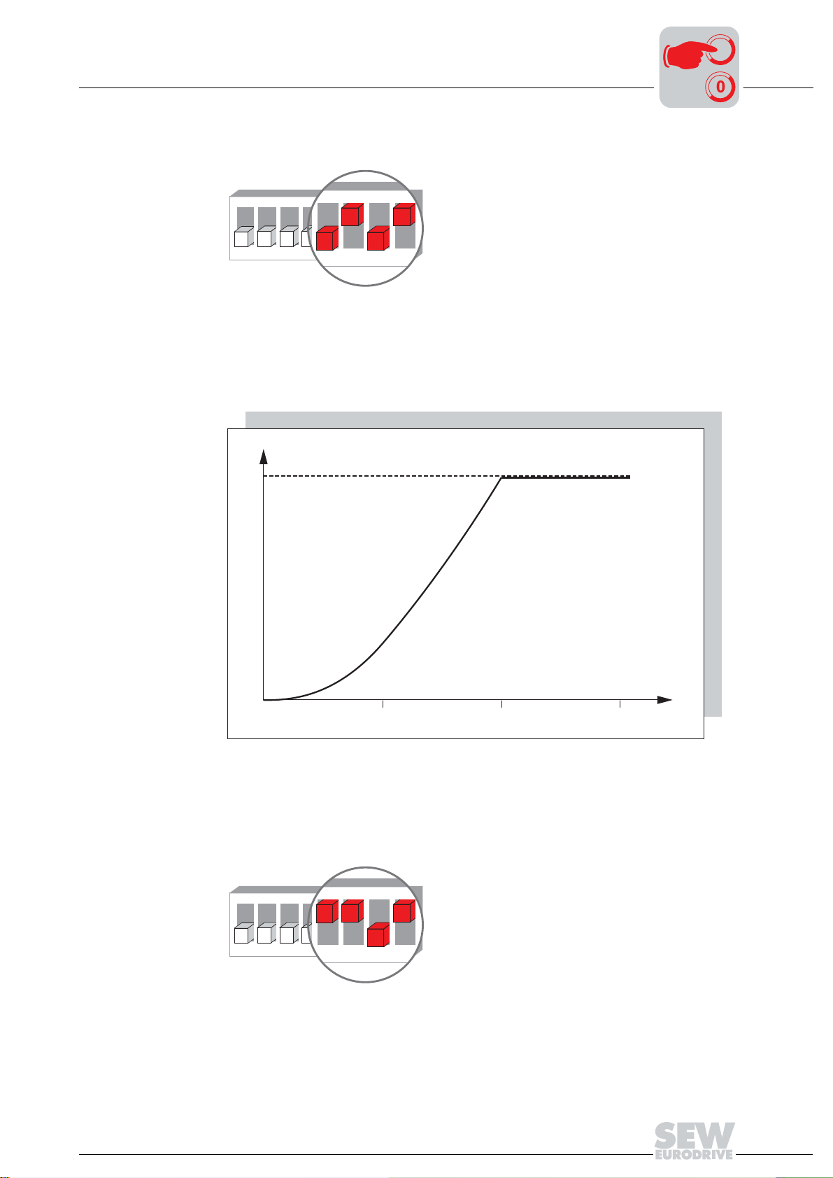
Startup of Standard Design
6
7
85
6
7
85
Selectable special functions MM..C-503-00
I
7
00
Special function 10
Function description
MOVIMOT® with reduced torque at low frequencies
S2
ON
1
3
2
4
6
85
7
05606AXX
• The drive builds up only a reduced torque due to a reduction in slip compensation
and active current at low speeds (see the following figure):
• Minimum frequency = 0 Hz (see special function 8 on page 68).
[1]
M
Special function 11
Function description
[2]
5
[1] Maximum torque with VFC operation
[2] Maximum torque with activated special function
10 15
f [Hz
]
Deactivation of phase fault control
S2
ON
1
3
2
4
6
85
7
06378AXX
• Phase control does not take place if the special function is activated.
• This is meaningful, for example, for supply systems with brief asymmetry.
50907AXX
Operating Instructions – MOVIMOT® MM03C - MM3XC
71
Page 72

7
6
7
85
I
Startup of Standard Design
Selectable special functions MM..C-503-00
00
Special function 12
Functional description
"Motor protection
function via TH
analysis" partial
function
MOVIMOT® with rapid start/stop and motor protection via TH
S2
ON
1
3
2
4
6
85
7
06379AXX
• The special function is active in terminal and bus operation, but there are differences
with respect to the usable functional scope.
• If the MOVIMOT
®
inverter is mounted close to the motor (with option P2.A or in the
field distributor), the special function consists of the following:
– Motor protection function via indirect TH analysis using direction of rotation termi-
nals
– Rapid start and stop function
This function is active only in bus operation. The special function implements tripping
fault 84 "Excessive motor temperature."
Fault 84 is tripped if all
• The standard MOVIMOT
of the following requirements are met:
®
motor protection function can be deactivated via DIP
switch S1/5 = ON.
• The direction of rotation terminals are wired to 24 V via a TH as shown in the following figure.
With field distributor:
L
R
TH
24V
TH
52119AXX
With mounting on motor
with option P2.A:
L
24V
TH
R
52120AXX
• The TH tripped due to excessive temperature of the motor (release of both direction
of rotation terminals does not apply).
• Mains voltage is present.
The motor protection function via TH analysis can be deactivated by setting DIP switch
S1/5 = OFF. In this case, the motor protection in the MOVIMOT
®
that is implemented
via motor model is in effect.
72
Operating Instructions – MOVIMOT® MM03C - MM3XC
Page 73

Startup of Standard Design
Selectable special functions MM..C-503-00
I
7
00
"Rapid start" partial
function
"Rapid stop" partial
function
Regardless of whether MOVIMOT® is controlled in terminal or bus operation, the premagnetization is fixed at 0 s, i.e. pre-magnetization does not take place at the beginning
of the release to start accelerating at the setpoint ramp as quickly as possible.
The new function "Brake applied at down ramp" is introduced in bus operation. Bit 9 is
assigned with this function as virtual terminal in the control word.
15 14 13 12 11 10 9876543210
Bit
Not assigned
Not assigned
"9"
As soon as bit 9 is set during the down ramp, MOVIMOT
(brake control is carried out through MOVIMOT
"1" =
Reset
Virtual terminal for "Brake applied at down ramp"
®
) or via the MOVIMOT® signal relay out-
Not assigned
®
directly applies the brake
"1 1 0" = Release
otherwise stop
put (brake control is carried out through relay output) and blocks the output stage.
If the motor frequency is lower than the stop frequency (3 Hz), the brake is applied in-
dependent of the status of bit 9 during the down ramp.
"Brake control in bus operation" flowchart:
1
[1]
0
[2]
n
1
[3]
0
1
[4]
0
[1] Enable terminals/control word
[2] Speed
[3] Bit 9
[4] Brake control signal: 1 = open, 0 = closed
t
t
t
t
06381AXX
In terminal operation, the rapid stop function via control word bit 9 is not
available.
Operating Instructions – MOVIMOT® MM03C - MM3XC
73
Page 74

I
7
Startup of Standard Design
Selectable special functions MM..C-503-00
00
Functionality of the signal relay
Special function 12
MOVIMOT
motor protection in Z.7 and Z.8 field distribu-
®
with rapid start/stop and
tor
Operating mode
Connected to terminals
13, 14 + 15 or 13 + 15
Relay function Ready relay
...Brake
Bus opera-
tion
...Braking
resistor
Brake relay
(see page
75)
...Brake
Ready relay
Terminal
operation
...Braking
resistor
Brake relay
(see page
75)
74
Operating Instructions – MOVIMOT® MM03C - MM3XC
Page 75

Startup of Standard Design
Selectable special functions MM..C-503-00
I
7
00
Use of relay output with special
functions 7, 9 and
12
The following figure shows the use of relay contact K1 to control the mechanical brake
with brake rectifier BGM.
Important: Please observe the following before startup with brake control BGM:
• The brake coil must correspond to the supply voltage (e.g. 400 V).
• Special function 7, 9 or 12 must be activated, otherwise the brake is perma-
nently released. This must also be observed in the case of an exchange of the
MOVIMOT
®
inverter.
If neither of the listed functions is activated, relay contact K1 functions as ready signal contact. This means that the brake will be released without enable if the
BGM is used, if it was connected without permission.
L1
L2
L3
PE
L1
L2
F11/F12/F13
K11
L3
MOVIMOT
MOVIMOT
[1]
BGM
RD
+
U
IN
BU
_
BK
~~
U
E
BK
13
14
15
[1] Brake control BGM installed in the terminal box
[2] External braking resistor BW (see the "Technical Data" section for the assignment)
[3] 24 V
[4] CW/Stop
[5] CCW/Stop
[6] Setpoint toggle f1/f2
[7] Brake relays
supply
DC
Observe the enabled direction of rotation (see the section "Connection of MOVIMOT® Basic
Unit" functions of CW/ Stop, CCW/Stop terminals with control via RS-485 interface)
RD
WH
BU
M
3~
13
[2]
14
BMG
15
[3]
=
DC
24 V
24V
+
-
[4]
[7]
K1a
K1
K1b
RS-485
RS-
RS+
52121AXX
[5]
[6]
f1/f2
R
L
Operating Instructions – MOVIMOT® MM03C - MM3XC
75
Page 76

7
I
Startup of Standard Design
Selectable special functions MM..C-503-00
00
Retrofitting the
brake rectifier
If the brake rectifier BGM was not ordered as installed option, it must be retrofitted as
follows:
The installation is only allowed in conjunction with modular terminal box!
1. Exchange the brake coil (brake coil must correspond to the supply voltage).
2. Mount the brake control BGM with two screws according to the following figure (connection according to wiring diagram on page 75).
52122AXX
3. Connect the external braking resistor according to the wiring diagram on page 75
(see the "Technical Data" section for assignment).
76
Operating Instructions – MOVIMOT® MM03C - MM3XC
Page 77

Startup of Standard Design
1
ON
432
Startup with binary control (control via terminals)
7.6 Startup with binary control (control via terminals)
1. Isolate MOVIMOT® drive from the supply, safeguarding it against unintentional
power-up! Dangerous voltages may still be present for up to 1 minute after
shutdown!
2. Review correct connection of MOVIMOT
tion").
3. Ensure that DIP switches S1/1 – S1/4 are set to OFF (= address 0).
ON
1
2
543
6
8
7
05062AXX
4. Set first speed with f1 setpoint potentiometer (activated if terminal f1/f2 = '0') (factory
setting: approx. 50 Hz).
®
(see the section "Electrical Installa-
I
7
00
100
f [Hz
]
6
5
[1] Pot. position
3
4
5
6
7
8
5. Set the second speed with switch f2 (active when tl. f1/f2 = "1").
Switch f2
Detent position012345678910
Setpoint f2 [Hz] 5 7 10 15 20 25 35 50 60 70 100
75
50
25
2
123456789100
[1]
f
1
05066BXX
During operation, the first speed is infinitely variable using the setpoint potentiometer f1 which is accessible from outside.
Speeds f1 and f2 can be set independently to any value.
6. Set the ramp time with switch t1 (ramp times in relation to a setpoint step change of
3
4
5
6
7
8
50 Hz).
Switch t1
Detent position 012345678910
Ramp time t1 [s] 0.1 0.2 0.3 0.5 0.7 1 2 3 5 7 10
7. Place the MOVIMOT
®
inverter on the terminal box and secure it.
8. Re-insert screw plug of setpoint potentiometer f1 with gasket.
9. Switch on the control voltage 24 V
and power supply.
DC
Operating Instructions – MOVIMOT® MM03C - MM3XC
77
Page 78

7
Inverter response according to the terminal level
I
Startup of Standard Design
Startup with binary control (control via terminals)
00
Network 24 V f1/f2 CW/Stop CCW/Stop Status LED Inverter
0 0 x x x Off Inverter off
1 0 x x x Off Inverter off
0 1 x x x Flashing
11x00YellowStop
11010GreenClockwise with f1
11001GreenCounterclock-
11110GreenClockwise with f2
11101GreenCounterclock-
11x11YellowStop
yellow
behavior
Stop, supply sys-
tem missing
wise with f1
wise with f2
Legend
0 = No voltage
1 = Voltage
X = Any
78
Operating Instructions – MOVIMOT® MM03C - MM3XC
Page 79

Startup of Standard Design
1
ON
2
Startup with options MBG11A or MLG11A
7.7 Startup with options MBG11A or MLG11A
1. Isolate MOVIMOT® drive from the supply, safeguarding it against unintentional
power-up! Dangerous voltages may still be present for up to 1 minute after
shutdown!
2. Review correct connection of MOVIMOT
tion").
3. Set DIP switch S1/1 (on MOVIMOT
ON
1
2
543
6
7
05064AXX
8
®
(see the section "Electrical Installa-
®
) to ON (= address 1).
I
7
00
4. Set the minimum frequency f
3
4
5
6
7
8
Switch f2
Detent position 012345678910
Minimum frequency f
[Hz]
min
2 5 7 1012152025303540
with switch f2.
min
5. Set the ramp time with switch t1 (ramp times in relation to a setpoint step change of
50 Hz).
3
4
5
6
7
8
Switch t1
Detent position 012345678910
Ramp time t1 [s] 0.10.20.30.50.71235710
6. Check whether the required direction of rotation is enabled.
Terminal R Terminal L Message
Activated Activated • Both directions of rotation are enabled
24V
R
L
Activated Not activated • Only clockwise direction of rotation is enabled
• Preselected setpoints for counterclockwise rotation result in
standstill of drive
24V
Not activated Activated • Only counterclockwise direction of rotation is enabled
24V
Not activated Not activated • Unit is blocked or the drive is stopped
24V
Operating Instructions – MOVIMOT® MM03C - MM3XC
R
L
• Setpoint selections for clockwise lead to the drive being
stopped
R
L
R
L
79
Page 80

7
I
Startup of Standard Design
Startup with options MBG11A or MLG11A
00
7. Place the MOVIMOT® inverter on the terminal box and secure it.
8. Set the required maximum speed using setpoint potentiometer f1.
100
f [Hz
]
6
5
75
50
25
f
1
[1] Pot. position
2
123456789100
[1]
9. Re-insert screw plug of setpoint potentiometer f1 with gasket.
10.Switch on the voltage.
05066BXX
80
Operating Instructions – MOVIMOT® MM03C - MM3XC
Page 81

Operating options MBG11A and MLG11A
Function Explanation
Display
Negative display value e.g.: = Counterclockwise rotation
Startup of Standard Design
Startup with options MBG11A or MLG11A
50
I
7
00
Increasing the speed
Reducing the speed
Blocking MOVIMOT
Enable MOVIMOT
Change in direction of
rotation from CW to
CCW
Change in direction of
rotation from CCW to
CW
®
®
Positive display value e.g.: = Clockwise rotation
The displayed value indicates the speed set with the setpoint potentiometer f1. Example: Display "50" = 50 % of the speed set with setpoint potentiometer.
Important: If the display is "0," the drive is turning at f
With CW rotation: With CCW rotation:
With CW rotation: With CCW rotation:
Press the following keys simultaneously: Display =
or
Important: After release, MOVIMOT
saved last.
1. Until display =
50
.
min
+
®
accelerates to the value and direction of rotation
0FF
0
2. Pressing it again changes direction of rotation from CW to CCW.
1. Until display =
0
2. Pressing it again changes direction of rotation from CCW to CW.
Memory function After the power supply system has been switched off and on again, the value last set is
retained provided the 24 V supply was present for at least 4 seconds following the most
recent setpoint change.
Operating Instructions – MOVIMOT® MM03C - MM3XC
81
Page 82

1
ON
2
I
7
Startup of Standard Design
Startup with MWA21A option (speed control module)
00
7.8 Startup with MWA21A option (speed control module)
1. Isolate MOVIMOT® drive from the supply, safeguarding it against unintentional
power-up! Dangerous voltages may still be present for up to 1 minute after
shutdown!
2. Review correct connection of MOVIMOT
tion").
3. Set DIP switch S1/1 (on MOVIMOT
ON
1
2
543
6
®
8
7
05064AXX
) to ON (= address 1).
®
(see the section "Electrical Installa-
4. Set the minimum frequency f
3
4
5
6
7
8
Switch f2
Detent position 012345678910
Minimum frequency f
[Hz]
min
2 5 7 1012152025303540
with switch f2.
min
5. Set the ramp time with switch t1 (ramp times in relation to a setpoint step change of
50 Hz).
3
4
5
6
7
8
Switch t1
Detent position 012345678910
Ramp time t1 [s] 0.10.20.30.50.71235710
6. Check whether the required direction of rotation is enabled.
Terminal R Terminal L Message
Activated Activated • Both directions of rotation are enabled
24V
R
L
Activated Not activated • Only clockwise direction of rotation is enabled
• Preselected setpoints for counterclockwise rotation result in
standstill of drive
82
24V
R
L
Not activated Activated • Only counterclockwise direction of rotation is enabled
24V
R
L
Not activated Not activated • Unit is blocked or the drive is stopped
24V
R
L
• Setpoint selections for clockwise lead to the drive being
stopped
Operating Instructions – MOVIMOT® MM03C - MM3XC
Page 83

Startup of Standard Design
Startup with MWA21A option (speed control module)
7. Place the MOVIMOT® inverter on the terminal box and secure it.
8. Set the required maximum speed using setpoint potentiometer f1.
100
f [Hz
]
6
5
75
50
25
I
7
00
f
1
(1) Pot. setting
2
123456789100
[1]
05066BXX
9. Re-insert screw plug of setpoint potentiometer f1 with gasket.
10.Select the signal type for the analog input (terminals 7 and 8) of the MWA21A option
using switches S1 and S2.
S1 S2 Setpoint stop function
V signal 0...10 V OFF OFF
I signal 0...20 mA ON OFF
I signal 4...20 mA ON ON
V signal 2...10 V OFF ON
No
Yes
11.Switch on the voltage.
12.Release MOVIMOT
®
by applying +24 V to tl. 4 (CW rotation) or tl. 5 (CCW rotation)
of the MWA21A.
Operating Instructions – MOVIMOT® MM03C - MM3XC
83
Page 84

7
I
Startup of Standard Design
Startup with MWA21A option (speed control module)
00
Control
Setpoint stop function:
MOVIMOT® is controlled from f
min
to f
using the analog signal at terminal 7 and ter-
max
minal 8.
6 10V
[1]
2 k
7 +
8
9
10
-
[2]
MWA21A
[1] Potentiometer using the 10 V reference voltage (alternatively 5 kΩ)
[2] Floating analog signal
[Hz]
[1]
5
4
3
6 10V
7 +
8
9
10
MWA21A
-
05067BXX
f
min
(2 Hz)
1
0
0 0,5
0 1 2
Setting: [1] Output frequency
0...10V / 0...20 mA
2...10V / 4...20 mA
1
[2] Setpoint
1,5
3
2 2,5
4 5
[V]
[mA]
[2]
05068BXX
84
Operating Instructions – MOVIMOT® MM03C - MM3XC
Page 85

Startup of Standard Design
1
ON
432
Startup with external AS-i binary slave MLK11A
7.9 Startup with external AS-i binary slave MLK11A
1. Isolate MOVIMOT® drive from the supply, safeguarding it against unintentional
power-up! Dangerous voltages may still be present for up to 1 minute after
shutdown!
2. Review correct connection of MOVIMOT
tion").
3. Ensure that DIP switches S1/1 – S1/4 are set to OFF (= address 0).
ON
1
2
4. Set first speed with f1 setpoint potentiometer (activated if terminal f1/f2 = '0') (factory
setting: approx. 50 Hz).
543
6
8
7
05062AXX
I
00
®
(see the section "Electrical Installa-
7
100
f [Hz
]
[1] Pot. position
6
5
75
50
25
2
123456789100
[1]
f
1
05066BXX
5. Set the second speed with switch f2 (active when tl. f1/f2 = "1").
3
4
5
6
7
8
Switch f2
Detent position012345678910
Setpoint f2 [Hz] 5 7 10 15 20 25 35 50 60 70 100
During operation, the first speed is infinitely variable using the setpoint potentiometer f1 which is accessible from outside.
Speeds f1 and f2 can be set independently to any value.
6. Set the ramp time with switch t1 (ramp times in relation to a setpoint step change of
50 Hz).
3
4
5
6
7
8
Switch t1
Detent position 012345678910
Ramp time t1 [s] 0.1 0.2 0.3 0.5 0.7 1 2 3 5 7 10
7. Place the MOVIMOT
®
inverter on the terminal box and secure it.
8. Re-insert screw plug of setpoint potentiometer f1 with gasket.
9. Connect AS-i supply voltage and supply.
Operating Instructions – MOVIMOT® MM03C - MM3XC
85
Page 86

7
I
Startup of Standard Design
Startup with external AS-i binary slave MLK11A
00
Data from AS-i
master to
MLK11A
Data from
MLK11A to AS-i
master
LED display
The following table shows the 4 data bits that are transferred from the AS-i master to the
MLK11A via the AS-Interface:
Bit Function Display / LED color
D0 Clockwise (terminal R) DO 0 / yellow
D1 Counterclockwise (terminal L) DO 1 / yellow
D2 Speed f1 / speed f2 (terminal f1/ f2) DO 2 / yellow
D3 Voltage supply / reset (terminal 24 V) DO3 / green
The following table shows the 4 data bits that are transferred from the MLK11A to the
AS-i master via the AS-Interface:
Bit Function Display / LED color
D0 Ready signal (relay K1) DI 0 / yellow
D1 -D2 Sensor 1 (M12 socket, pin 4) DI 2 / yellow
D3 Sensor 2 (M12 socket, pin 2) DI 3 / yellow
[1]
[2]
[3]
[4]
[1] MOVIMOT® ready for operation
[2] External input DI2
[3] External input DI3
[4] Voltage supply via AS-i system is ok
DI0
DI2
DI3
AS-i
Power
DO0
DO1
DO2
DO3
[5] Clockwise rotation activated
[6] Counterclockwise rotation activated
[7] Speed f2 activated
[8] MOVIMOT
®
voltage supply
[5]
[6]
[7]
[8]
05070BXX
86
Operating Instructions – MOVIMOT® MM03C - MM3XC
Page 87

Startup of Standard Design
Startup with external AS-i binary slave MLK11A
I
7
00
Assigning slave
address via handheld programming device
An AS-i hand-held programming device can be used to assign the slave address. This
allows simple and network-independent addressing.
The AS-i hand-held programming devices offer the following functions:
• Reading and changing an AS-i slave address
• Reading the AS-i profile
• Reading and changing the data bits
• Functional test and test operation (the functional test and test operation require an
external voltage supply since hand-held programming devices do not supply sufficient current for operation).
The use of a hand-held programming device requires a connecting cable that fits onto
the M12 plug connector of the MLK11A (see the following figure).
AS-i -
N.C.
4
3
2
1
AS-i +
N.C.
05135AXX
Example: Every AS-i station is individually addressed (A) and then reintegrated in the
AS-i network (B).
[1]
[1] AS-i hand-held programming
device
A
B
52308AXX
Operating Instructions – MOVIMOT® MM03C - MM3XC
87
Page 88

I
7
Startup of Standard Design
Additional information for mounting close to the motor
00
7.10 Additional information for mounting close to the motor
If the MOVIMOT® inverter with option P2.A is mounted close to the motor, you need to
observe the following instructions:
Checking the
method of connection for the
connected motor
Motor protection and direction of rotation enable
Use the following figure to verify that the selected connection method of MOVIMOT® is
identical for the connected motor.
W2 U2 V2
댴 쑶
U1 V1 W1
W2 U2 V2
U1 V1 W1
03636AXX
Important: For brake motors: Do not install brake rectifiers inside the terminal box
of the motor!
The connected motor must be equipped with a TH.
• If control is carried out via RS-485, the TH must be wired as follows:
A
MOVIMOT
24V
TH
®
R
L
MOVIMOT
BC
24V
TH
®
R
L
MOVIMOT
24V
TH
®
R
L
52257AXX
[A] Both directions of rotation are enabled
[B] Only counterclockwise direction of rotation is enabled
[C] Only clockwise direction of rotation is enabled
• If control is carried out via binary signals, SEW recommends connecting the TH in
series with the "ready signal" relay (see the following figure).
– The ready signal must be monitored be an external control.
– As soon as the ready signal is no longer available, the drive must be switched off
(tl. R and L = "0").
24V
TH
MOVIMOT
L
R
SPS
K1a
®
K1b
52253AXX
88
Operating Instructions – MOVIMOT® MM03C - MM3XC
Page 89

Startup of Standard Design
Additional information for mounting close to the motor
I
7
00
DIP switch
Braking resistor
With mounting of the MOVIMOT® inverter close to the motor, set DIP switch S1/5 to ON
which is different than the factory setting.
S1 1 2 3 4 5
Message RS-485 address
2021222
ON 1111 Off
OFF 0000 On adapted 4 kHz Off
Motor
3
protec-
tion
6
Motor
rating class
Motor one
size smaller
7
PWM
frequency
Variable
(16, 8, 4 kHz)
8
No-load
damping
On
• With motors without brakes, an internal braking resistor (BW1 or BW2) must be connected to the MOVIMOT
• With brake motors, no braking resistor may be connected to the MOVIMOT
®
.
14
®
15
06487AXX
®
.
MOVIMOT
13
BW1 / BW2
Mounting of the
MOVIMOT
®
inverter in the
field distributor
Observe the instructions in the corresponding manuals when mounting the MOVIMOT
inverter close to the motor in the field distributor:
• PROFIBUS Interfaces, Field Distributors
• InterBus Interfaces, Field Distributors
• DeviceNet/CANopen Interfaces, Field Distributors
• AS-Interfaces, AS-i field distributors
®
Operating Instructions – MOVIMOT® MM03C - MM3XC
89
Page 90

I
8
Startup with Integrated AS-Interface
Important startup instructions
00
8 Startup with Integrated AS-Interface
8.1 Important startup instructions
• It is essential to comply with the safety notes during installation!
• Before removing/attaching the MOVIMOT
from the power supply system (mains). Dangerous voltages may still be
present for up to 1 minute after shutdown.
• Ensure before startup that the drive has not been damaged.
• Check that all protective covers are installed correctly.
• A minimum switch-off time of 2 seconds must be maintained for the mains contactor
K11.
8.2 Description of the controls
®
inverter, it must be disconnected
Setpoint potentiometer f1
Setpoint switch f2
3
4
5
6
7
8
The potentiometer is used to adjust setpoint f1:
100
f [Hz
]
[1] Pot. position
6
5
75
50
25
2
123456789100
[1]
f
1
05066BXX
Setpoint f1 is selected via the AS-i bit "speed f1/speed f2".
The switch is used to adjust setpoint f2:
Switch f2
Detent position 0 12345678910
Setpoint f2 [Hz] 5 7 1015202535506070100
Setpoint f2 is selected via the AS-i bit "speed f1/speed f2".
90
Switch t1
3
For integrator ramp (ramp times based on a setpoint jump of 50 Hz)
4
5
6
7
8
Switch t1
Detent position 012345 678910
Ramp time t1 [s] 0.1 0.2 0.3 0.5 0.7 1 235710
Operating Instructions – MOVIMOT® MM03C - MM3XC
Page 91

DIP switches S3 and S4
Startup with Integrated AS-Interface
Description of the controls
I
8
00
51858AXX
DIP switch S3:
S3 1 2 3 4 5 6
Message Motor
protection
ON Off
OFF On adapted 4 kHz Off IEC motor Off
1) only available in Brazil
Motor
rating class
Motor one
size smaller
PWM
frequency
Variable
(16, 8, 4
kHz)
No-load
damping
On
Motor type Brake release
SEW DZ
1)
motor:
without
Enable
On
DIP switch S4:
S4 1 2 3 4 5 6
Message Control process Speed
monitoring
ON V/f On 1111
OFF VFC Off 0000
Selection of options
0
2
1
2
2
2
3
2
Operating Instructions – MOVIMOT® MM03C - MM3XC
91
Page 92

I
8
Startup with Integrated AS-Interface
Description of the DIP switches S3
00
8.3 Description of the DIP switches S3
DIP switch S3/1
DIP switch S3/2
Motor protection activated or deactivated
• If the MOVIMOT
®
inverter is mounted close to the motor (with option P2.A or in the
field distributor), the motor protection must be deactivated.
• To ensure motor protection after all, a TH (bimetallic thermostat) must be used.
Motor rating class smaller
• If it is activated, the DIP switch enables the assignment of MOVIMOT
®
to a motor
with a smaller rating class. The rated power of the unit remains unchanged.
• If a motor with less power is used, the overload capacity of the drive may increase
since the motor considers the MOVIMOT
®
to be one power increment too high. A
larger current may be impressed for a short period of time, which results in higher
torques.
• The purpose of switch S3/2 is the short-term utilization of the motor peak torque. The
current limit of the respective unit is always the same, independent of the switch setting. The motor protection function is adapted in reference to the switch setting.
• In this operating mode with S3/2 = "ON", a pull-out protection of the motor is
not possible.
MOVIMOT®
inverter
S3/2 = OFF S3/2 = ON
Assigned motor
댴 쑶 댴 쑶
MM03 DT71D4 DR63L4
MM05 DT80K4 DT71D4 DT71D4 DFR63L4
MM07 DT80N4 DT80K4 DT80K4 DT71D4
MM11 DT90S4 DT80N4 DT80N4 DT80K4
MM15 DT90L4 DT90S4 DT90S4 DT80N4
MM22 DV100M4 DT90L4 DT90L4 DT90S4
MM30 DV100L4 DV100M4 DV100M4 DT90L4
MM3X – DV100L4 DV100L4 DV100M4
1) Only possible with offset assembly
1)
DR63L4
1)
–
1)
DIP switch S3/3
DIP switch S3/4
92
Setting the maximum PWM frequency
• With setting DIP SWITCH S3/3 = OFF, MOVIMOT
®
operates with 4 kHz PWM fre-
quency.
• With setting DIP SWITCH S3/3 = ON, MOVIMOT
®
operates with a 16 kHz PWM frequency (low noise) and switches back in steps to lower switching frequencies depending on the heat sink temperature.
No-load damping function (S3/4 = ON)
Upon activation, the function prevents resonant oscillations in no-load operation.
Operating Instructions – MOVIMOT® MM03C - MM3XC
Page 93

Startup with Integrated AS-Interface
Description of the DIP switches S3
I
8
00
DIP switch S3/5
DIP switch S3/6
Operation with
braking resistor
Releasing the
brake
Motor type
With IEC and NEMA motors, DIP switch S3/5 must always be set to OFF, for Brazilian
motors to ON.
Releasing the brake without enable
With activated switch S3/6 = "ON", the brake can also be released if no drive enable is
present.
The special function is not in effect if operated with braking resistor.
The brake can be released under the following conditions by setting the AS-i bit "speed
f1/speed f2":
Status of
AS-i bit
D0
D1
(R)
"1"
"0"
"1"
"0"
"1"
"0"
"1" "1" "1" Unit not
"0" "0" "1" Unit not
All conditions possible
D2
(L)
(f1/f2)
"0"
"0" Unit enabled No
"1"
"0"
"1" Unit enabled No
"1"
"1"
"0" Unit not
"0"
Enable condition Fault condi-
enabled
enabled
enabled
Unit not
enabled
tion
Unit fault
Unit fault
No
Unit fault
No
Unit fault
No
Unit fault
Unit fault Brake closed
Brake function
Brake is controlled by MOVIMOT
setpoint f1
Brake is controlled by MOVIMOT
setpoint f2
Brake closed
Brake closed
Brake released for manual procedure
®
,
®
,
Setpoint selection
Behavior with a
non-operating unit
LED display
Bit D3 (Reset/Controller enable) must be set to enable the drive.
Setpoint selection dependent on AS-i bit "speed f1/speed f2":
Enable condition AS-i bit Active setpoint
Unit enabled D2 = "0" Setpoint potentiometer f1 active
Unit enabled D2 = "1" Setpoint potentiometer f2 active
In case of a non-operating unit, the brake is always applied independent of the setting
of AS-i bit "speed f1/speed f2".
The yellow LED display flashes periodically and quickly (ton : t
= 100 ms : 300 ms) if
off
the brake was released for manual procedure.
Operating Instructions – MOVIMOT® MM03C - MM3XC
93
Page 94

I
8
Startup with Integrated AS-Interface
Description of the DIP switches S4
00
8.4 Description of the DIP switches S4
DIP switch S4/1
DIP switch S4/2
DIP switches
S4/3 to S4/6
Control process
• DIP switches S4/1 = OFF: VFC operation for 4-pole motors
• DIP switches S4/1 = ON: U/f operation reserved for special cases
Speed monitoring
• Speed monitoring (S4/2 = "ON") is used for the protection of the drive during blocking.
• If the drive is operated at the current limit for more than 1 second with active speed
®
monitoring (S4/2 = "ON"), the speed monitoring trips. MOVIMOT
signals a fault via
status LED (red, flashing slowly, fault code 08). The current limit must be attained uninterruptedly for the duration of the delay time before the monitoring function
responds.
Selection of options
• Special functions can be selected using the binary coding of the DIP switches.
• The possible values can be set as follows:
Decimal
value
S4/3 –
S4/4 ––
S4/5 ––––
S4/6 ––––––––
0 1 2 3 4 5 6 7 8 9 10 11 12 13 14 15
X – X – X – X – X – X – X – X
X X ––X X ––X X ––X X
X X X X ––––X X X X
X X X X X X X X
X = ON
–= OFF
• An overview of the selectable special functions can be found on page 58.
94
Operating Instructions – MOVIMOT® MM03C - MM3XC
Page 95

Startup with Integrated AS-Interface
Selectable special functions MM..C-503-30
8.5 Selectable special functions MM..C-503-30
Overview of
selectable special
functions
Decimal
value
0 Basic functionality, no special function selected – –
1 MOVIMOT
2 MOVIMOT
3 MOVIMOT
4 Not possible with MOVIMOT
5 Not possible with MOVIMOT
6 MOVIMOT
7 MOVIMOT
8 MOVIMOT
9 Not possible with MOVIMOT
10 MOVIMOT
11 Monitoring of supply phase fault is deactivated – page 101
12 Not possible with MOVIMOT
12 to 15 Not assigned – –
Brief description Limitations see page
®
with increased ramp times – page 96
®
(fault if exceeded)
(switchable via terminal f1/f2)
quency
reduced torque at low frequencies
with adjustable current limitation
®
with adjustable current limitation
®
with integrated AS-Interface –
®
with integrated AS-Interface –
®
with maximum 8 kHz PWM fre-
®
with rapid start / stop Rapid stop not possible page 99
®
with minimum frequency 0 Hz – page 100
®
with integrated AS-Interface –
®
with minimum frequency 0 Hz and
®
with integrated AS-Interface –
I
8
00
–
–
–
–
page 96
page 97
page 99
page 101
Operating Instructions – MOVIMOT® MM03C - MM3XC
95
Page 96

8
4
5
63
4
5
63
I
Startup with Integrated AS-Interface
Selectable special functions MM..C-503-30
00
Special function 1
Function description
Changed ramp
times
3
4
5
6
7
8
Special function 2
MOVIMOT® with increased ramp times
S4
ON
1
2
6
7
51859AXX
85
• It is possible to set ramp times up to 40 s.
Switch t1
Detent position 0123456 7 8 9 10
Ramp time t1 [s] 0.1 0.2 0.3 0.5 0.7 1
= Corresponds to standard setting
= Changed ramp times
20 25 30 35 40
MOVIMOT® with adjustable current limitation (fault if exceeded)
Function description
Adjustable current
limits
3
4
5
6
7
8
S4
ON
1
2
6
7
51860AXX
85
• The current limit can be set via switch f2.
• Setpoint f2 can no longer be changed and is fixed at the following value:
– Setpoint f2: 5 Hz
• Monitoring becomes effective above 15 Hz. If the drive is operated at the current limit
for more than 500 ms, the unit changes to the fault status (fault 44). The status is indicated through rapid red flashing.
Switch f2
Detent position 012345678910
I
max
[%] of I
N
90 95 100 105 110 115 120 130 140 150 160
96
Operating Instructions – MOVIMOT® MM03C - MM3XC
Page 97

Startup with Integrated AS-Interface
4
5
63
Selectable special functions MM..C-503-30
I
8
00
Special function 3
Function description
Response after
reaching the current limitation
In-system values
for setpoint f2/minimum frequency
MOVIMOT® with adjustable current limitation (switchable via AS-i bit "speed f1/
speed f2"), with reduction of frequency if exceeded
S4
ON
1
2
6
7
51861AXX
85
The current limitation can be set via switch f2. The AS-i bit "speed f1/speed f2" can be
used to toggle between maximum current limit and the current limitation set via switch f2.
• After reaching the current limit, the unit reduces the frequency using the current limitation function and if necessary stops the ramp to prevent the current from increasing.
• If the unit operates at the current limitation, the status is displayed through rapid
green flashing of the status LED.
• Switching via AS-i "speed f1/speed f2" between setpoint f1 and setpoint f2 is no
longer possible.
Adjustable current
limits
3
4
5
6
7
8
Selection of current limitation via
AS-i bit "speed f1/
speed f2"
Switch f2
Detent position 012345678910
[%] of I
I
max
AS-i bit "speed f1/speed f2" = 0 AS-i bit "speed f1/speed f2" = 1
Current limitation 160% Current limitation via switch f2
N
60 70 80 90 100 110 120 130 140 150 160
Operating Instructions – MOVIMOT® MM03C - MM3XC
97
Page 98

8
I
Startup with Integrated AS-Interface
Selectable special functions MM..C-503-30
00
Influencing the current characteristic
curve
By selecting a lower current limit, the calculation of the current limit is carried out with a
constant factor.
Motor with star connection
max
/ I
n
[%]
I
200
160
100
50
[1]
[2]
0
50
100
f [Hz]
50851AXX
[1] Current limit characteristic curve of standard function
[2] Reduced current limit characteristic curve for special function 3 and AS-i bit "speed f1/
speed f2"= "1"
Motor with delta connection
I
max
/ In [%]
200
160
100
50
[1]
[2]
0
50
10087
f [Hz]
98
50852AXX
[1] Current limit characteristic curve of standard function
[2] Reduced current limit characteristic curve for special function 3 and AS-i bit "speed f1/
speed f2"= "1"
Operating Instructions – MOVIMOT® MM03C - MM3XC
Page 99

Startup with Integrated AS-Interface
4
5
63
4
5
63
Selectable special functions MM..C-503-30
I
8
00
Special function 6
Function description
MOVIMOT® with maximum 8 kHz PWM frequency
S4
ON
1
2
6
7
51863AXX
85
• The special function reduces the maximum adjustable PWM frequency via S3/3 from
16 kHz to 8 kHz.
• When DIP switch S3/3 = "ON", the unit operates with an 8 kHz PWM frequency (low
noise) and switches back to 4 kHz depending on the heat sink temperature.
without
ON
OFF PWM frequency 4 kHz PWM frequency 4 kHz
PWM frequency variable
16, 8, 4 kHz
with
PWM frequency variable
S3/3
special function 6
S3/3
special function 6
8, 4 kHz
Special function 7
Function description
MOVIMOT® with rapid start
S4
ON
1
2
6
7
51864AXX
85
• The pre-magnetization time is fixed at 0 s.
• No pre-magnetization is carried out at the start of the release to begin the acceleration at the setpoint ramp as quickly as possible.
Operating Instructions – MOVIMOT® MM03C - MM3XC
99
Page 100
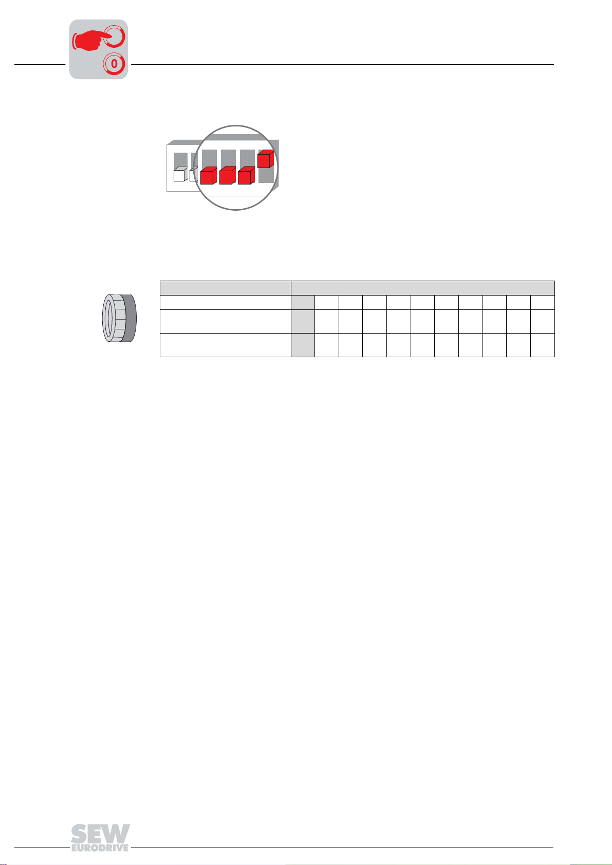
8
4
5
63
I
Startup with Integrated AS-Interface
Selectable special functions MM..C-503-30
00
Special function 8
Function description
3
4
5
6
7
8
MOVIMOT® with minimum frequency 0 Hz
S4
ON
1
2
6
7
51866AXX
85
If switch f2 is in position of rest 0, the setpoint f2 measures 0 Hz with activated special
function. All other adjustable values remain unchanged.
Switch f2
Detent position 0 12345678910
Setpoint f2 [Hz]
with activated special function
Setpoint f2 [Hz]
without special function
0 7 10 15 20 25 35 50 60 70 100
5 7 1015202535506070100
100
Operating Instructions – MOVIMOT® MM03C - MM3XC
 Loading...