

Metal Fab PIC, IPIC Installation Manual
INSTALLATION AND
MAINTENANCE
PIC
INSTRUCTIONS
IPIC
MODEL PIC/IPIC
CHIMNEY AND VENTS
A MAJOR CAUSE OF CHIMNEY RELATED FIRES IS
FAILURE TO MAINTAIN REQUIRED CLEARANCES
(air spaces) TO COMBUSTIBLE MATERIALS. IT IS OF
UTMOST IMPORTANCE THAT CHIMNEY BE INSTALLED
ONLY IN ACCORDANCE WITH THESE INSTRUCTIONS.
This symbol on the nameplate
means this product is listed by
Underwriters Laboratories Inc.
and by Underwriters
Laboratories of Canada
IMPORTANT: DO NOT INSTALL CHIMNEY WITHOUT
FIRST READING THESE INSTRUCTIONS
VERY CAREFULLY.
Metal-Fab’s Model PIC/IPIC Chimney has been fully tested and listed by Underwriters Laboratories, Inc.
and Underwriters Laboratories of Canada.
Chimneys installed in accordance with these installation instructions will comply with national safety
standards and building codes.
This booklet contains complete information on details concerning dimensions, installation, clearances to
combustibles, and use of non-combustible enclosures. For any additional construction information, refer
to Model PIC/IPIC Design Manual - L1690.
• BREECHING APPLICATIONS
• BOILER EXHAUST APPLICATIONS
• ENGINE/TURBINE EXHAUST APPLICATIONS
METAL-FAB, INC. • P.O. BOX 1138, WICHITA, KANSAS 67201 • (316)943-2351

GENERAL INFORMATION
LISTINGS
Metal-Fab Model PIC/IPIC Chimney is “listed” by Underwriters Laboratories, Inc (UL File No. MH8251) as “Building Heating Appliance
Chimney” for continuous operation at 1000ºF and intermittent operation (less than one hour) at 1400ºF. For higher temperature
applications, it is also “listed” as “1400ºF Factory Built Chimney” for continuous operation at 1400ºF and intermittent operation at
1800ºF. PIC/IPIC Chimney is “listed” by Underwriters Laboratories of Canada (ULC File No. CMH1272) as a continuous operation
“760ºC Factory-Built Chimney.” PIC/IPIC Chimney is “listed” for use at maximum 60-inch water column (2.19 psig) positive internal
pressure when installed in accordance with the section “PIPE AND FITTING ASSEMBLY” for 60 in.wc. in these instructions. See
TABLE 1 for clearances. For sizes 6” to 14” diameter: IPIC-2, IPIC-3 and IPIC-4 chimney is “Listed” to UL103-HT for use as a
Residential Chimney and is permitted to be installed within fully enclosed combustible construction at 2” min. clearance.
APPLICATIONS
Model PIC/IPIC building heating appliance chimneys are suitable for use with building heating appliances and other low heat
appliances as described in the Chimney Selection Chart of the National Fire Protection Association Standard No. 211, which produce
exhaust ue gas at a temperature not exceeding 1000ºF continuous. PIC/IPIC Chimneys are also suitable for use as complete
exhaust systems for diesel engines and gas turbines. The Model PIC/IPIC product line is listed for higher heat applications where
continuous temperatures are not in excess of 1400ºF and where the intermittent maximum temperatures are less than 1800ºF.
These chimneys are to be installed as required by NFPA for Factory Built Chimneys and Chimney Units. They are not to be enclosed
within combustible construction. An interior exhaust system is to be enclosed in a re resistive shaft of appropriate size and rating
where the exhaust system extends through any story of a building above that in which the connected appliance is located. An
unenclosed chimney may be placed adjacent to walls of combustible construction at the clearances specied herein. Consult local
authorities having jurisdiction.
Model PIC/IPIC chimneys are intended for use as complete systems connecting the appliance, engine or duct to the outdoors, or
as appliance connector, ue gas collector and breeching conveying ue gas to a stack built in conformance with NFPA 211, while
operating under positive forced draft, negative draft or neutral gravity ow internal pressure conditions.
The Model PIC/IPIC pipe is ideally suited to this application because it is a circular cross section (low friction loss), double-wall
insulated, high-strength to weight ratio design using high quality stainless steels.
Complete system size and capacity information can be obtained from the ASHRAE Handbook, Equipment Volume or by contacting
Metal-Fab, Inc., PO Box 1138, Wichita, KS 67201.
Refer to Metal-Fab Model PIC/IPIC Design Maual - L1690 for description of all necessary components.
MULTI-ENGINE EXHAUSTS NOT RECOMMENDED
Where multiple engines are being considered, it is recommended that they not be connected into one common exhaust system.
Exhaust gases tend to ow to cooler, non-operating engines, thereby causing formation of condensation. Consult with your engine
manufacturer before the installation of multiple engines vented into a common exhaust.
When designing engine exhaust systems:
• Provide correct pipe diameter and keep runs short with the minimum number of turns possible.
• Ensure that exhaust system is properly supported and is isolated from vibration.
• Pay particular attention to thermal expansion and placement of bellows joints.
• Provide proper condensation traps and drains.
EXPLOSION PROTECTION
The use of PIC/IPIC ttings such as lateral tees, wyes and elbows should be kept to a minimum to reduce back pressure and
accumulation of unburned fuels. When a change of direction is required in and engine exhaust system, ttings used for direction
change must be reinforced by means of plate support or wall support assemblies to prevent damage if an explosion caused by ignition
of unburned fuel should occur. Additionally, the exhaust system should be equipped with a relief valve if possible. For methods of
reinforcement and placement of relief valve, see section titled “ENGINE EXHAUST SYSTEM PRECAUTIONS.”
GREASE DUCT APPLICATIONS
Metal-Fab Model PIC/IPIC chimney is listed as grease duct for continuous temperature of 500ºF and intermittent temperatures of
2000ºF. Refer to the “Grease Duct Installation Manual L2502” for specic application information.
OPERATING PRECAUTIONS
CREOSOTE AND SOOT – Formation and Need for Removal
When wood is burned slowly, it produces tar and organic vapors which combines with expelled moisture to form creosote. The
creosote vapors condense in the relatively cool chimney ue of a slow burning re. As a result, creosote residue accumulates on the
ue lining. If ignited, this creosote makes an extremely hot re. For this reason, the chimney should be inspected at least once every
two months during the heating season to determine if a creosote or soot buildup has occurred. If creosote or soot has accumulated,
it should be removed to reduce risk of chimney re.
A licensed or qualied chimney sweep should be contacted to clean the chimney. Contact local building or re ofcials about
restrictions and installation inspection in your area. Adequate clearance is required around cleanouts to assure accessibility for
removal of caps and products accumulated within the chimney.
NOTE: Dimensions in these instructions are in American standard (feet and inches), with Metric (mm) in parenthesis except
stated otherwise.
2
CHIMNEY ENVIRONMENT
It is suggested that a chimney being installed in a corrosive
atmosphere be constructed of Type 316 stainless steel.
Type 316 stainless is resistant to corrosion and will add to
the life expectancy of the installation. Chemicals containing
halogen compounds should not be allowed to contaminate the
combustion air supplied to the heating equipment. Storage or
use of chemicals containing chlorine or chlorides in the vicinity
of equipment, or the presence of these compounds in the fuel,
or combustion air supply may lead to early deterioration of the
chimney.
Chemicals which may cause attack on chimney materials include
(but are not limited to):
• chlorinated or halogenated dry cleaning solutions,
• uorocarbon refrigerants,
• hydrochloric (muriatic), sulfuric or other acids,
• uorocarbon aerosol propellants,
• vinyl plastics (when burned),
• chlorine bleach and cleaning solutions,
• titanium tetrachloride, or
• plating or etching baths or solutions.
Any of these chemicals passing through the combustion process
produce acids which can corrode the heating equipment and the
chimney.
If corrosion is found, an immediate investigation should be
undertaken of the entire area. Any corrosive materials should
be removed to avoid future contamination. A contaminate-free
atmosphere for combustion and ventilation air must be obtained.
It may be necessary to pressurize the equipment room with its
own air supply. Any surface discoloration should be carefully
studied as it may be caused by contaminates in the fuel, or
corrosion of mild steel components of the chimney system, the
breeching system, or the equipment being vented and may be
indicative of deterioration of other components of the heating
system.
Whenever the local atmosphere is high in pollutants, constantly
or intermittently, it is recommended that the chimney components
be of all stainless steel construction. When chimney is exposed
to the elements, it is recommended that the outer wall be
either painted with one base coat and one nish coat of a heat
resistant primer and paint, or that the outer wall be constructed
of stainless steel.
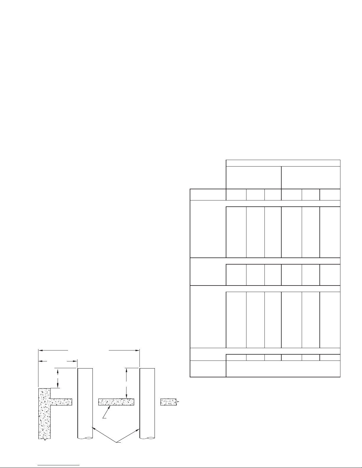
TERMINATION HEIGHT REQUIREMENTS
Model PIC/IPIC chimney is to terminate a minimum of 3’ (914)
above the highest point where it passes thru a roof of a building
and a minimum of 2’ (610) higher than any portion of a building
within a horizontal distance of 10’ (3.05m) (See FIG. 1).
FIG. 1 - TERMINATION HEIGHT REQUIREMENTS
MORE THAN 10’ (3048)
LESS THAN
10’ (3048)
2’ (610)
3’ MIN. (914)
STRUCTURE
CHIMNEY OR VENT
CLEARANCES – BOILERS AND ENGINES
CAUTION– DO NOT ENCLOSE IN A CHASE OR PASSAGEWAY
OF COMBUSTIBLE MATERIAL
For appliances operating with continuous exhaust temperatures
up to 1400º F, where the chimney is installed in an open room
or fully ventilated area on the same story as the appliance to
which it is connected, Model PIC/IPIC Chimney shall be installed
at a minimum of the clearance to combustibles as indicated in
TABLE 1.
Except for installation in one or two family dwellings, a factorybuilt chimney that extends through any zone above that on which
the connected appliance is located is to be provided with an
enclosure having a re resistance rating equal to or greater than
that of the oor or roof assemblies through which it passes.
Metal-Fab Model PIC/IPIC Chimney can penetrate a combustible
roof by utilizing the Roof Support Assembly (RSA) or Ventilated
Thimble Assembly (VTA). All other parts are for attachment to
non-combustible construction (i.e., oor guides, wall guides,
plate or wall support assemblies).
TABLE 1 - PIC/IPIC INSTALLATION CLEARANCES
Operating Temperature
1000°F Continuous
(538°C)
1400°F Intermittent
(760°C)
Insulation
Thickness
Exterior Wood Frame or Combustible Wall
Diameter: 6”
8 - 16”
24 - 26”
28 - 32”
36 - 40”
42 - 48”
Exterior Non-Combustible
Diameter: 6”
8 - 18”
20 - 42”
44 - 48”
Interior Wood or Other Combustibles
Diameter: 6”
8 - 16”
28 - 32”
36 - 40”
42 - 48”
Fully Enclosed Combustibles (UL103-HT)
Diameter: 6”-14” N/A N/A 2” (51) N/A N/A N/A
Fire Rated or
Non-Combustible
Chase
PIC IPIC-1
4” (102)
4” (102)
18”
5” (127)
20”
6” (152)
22”
6” (152)
6” (152)
6” (152)
34”
6” (152)
6” (152)
6” (152)
2” (51)
2” (51)
4” (102)
4” (102)
4” (102)
4” (102)
18”
5” (127)
20”
6” (152)
22”
7” (178)
24”
8” (204)
26”
9” (229)
10” (254)
34”
10” (254)
10” (254)
10” (254)
As necessary for installation and access, refer to NFPA 211.
4” (102)
5” (127)
5” (127)
6” (152)
4” (102)
4” (102)
5” (127)
5” (127)
6” (152)
1” (25)
2” (51)
3” (76)
3” (76)
3” (76)
3” (76)
1” (25)
2” (51)
3” (76)
1” (25)
2” (51)
3” (76)
3” (76)
3” (76)
3” (76)
3” (76)
IPIC-2
IPIC-4
1” (25)
1” (25)
1” (25)
1” (25)
1” (25)
1” (25)
1” (25)
1” (25)
1” (25)
1” (25)
1” (25)
1” (25)
1” (25)
1” (25)
1” (25)
1” (25)
1” (25)
1” (25)
1” (25)
1” (25)
1” (25)
1” (25)
1” (25)
3” (76)
3” (76)
Note: The above gures represent air space, in inches, from
outer surface to surroundings.
NOTES:
1. False ceilings are a potential hazard and require
restopping.Chimneyspassingthroughareasbetween
ceiling and roof must be installed in re-rated
enclosures in accordance with local building codes.
2. Decorative shrouds at the termination of a factory built
chimney shall not be permitted per NFPA 211.
3
1400°F Continuous
(760°C)
1800°F Intermittent
(982°C)
PIC IPIC-1
4” (102)
4” (102)
6” (152)
8” (204)
9” (229)
10” (254)
10” (254)
10” (254)
10” (254)
10” (254)
2” (51)
2” (51)
4” (102)
4” (102)
4” (102)
4” (102)
6” (152)
8” (204)
9” (229)
10” (254)
10” (254)
10” (254)
10” (254)
10” (254)
10” (254)
1” (25)
2” (51)
3” (76)
3” (76)
3” (76)
3” (76)
4” (102)
5” (127)
5” (127)
6” (152)
1” (25)
2” (51)
3” (76)
4” (102)
1” (25)
2” (51)
3” (76)
3” (76)
3” (76)
3” (76)
3” (76)
4” (102)
5” (127)
5” (127)
6” (152)
IPIC-2
IPIC-4
1” (25)
1” (25)
1” (25)
1” (25)
1” (25)
1” (25)
1” (25)
1” (25)
1” (25)
1” (25)
1” (25)
1” (25)
1” (25)
1” (25)
1” (25)
1” (25)
1” (25)
1” (25)
1” (25)
1” (25)
1” (25)
1” (25)
1” (25)
3” (76)
3” (76)
USE AND INSTALLATION OF INDIVIDUAL PARTS:
These instructions comprise both general and specic
requirements for all parts in the product line. Before specifying a
design or beginning an installation, these instructions should be
carefully reviewed.
PIPE WEIGHT
The average weight of the chimney, per foot of length, can be
calculated using the following formula:
PIC: 0.80 x diameter = lbs per foot
IPIC-1: 0.95 x diameter = lbs per foot
IPIC-2: 1.05 x diameter = lbs per foot
IPIC-4: 1.45 x diameter = lbs per foot
Example: 8IPIC-2: 1.05 x 8 = 8.4 lbs per foot
Chimney design should make provisions for support adequate to
ensure that chimney parts are not overloaded.
PART NUMBERS
These instructions identify Model PIC/IPIC parts by name of part
number in the text and illustrations. Actual parts also carry a ue
diameter prex and a three digit “CTO” sufx which denes the
materials of construction, such as 24IPIC30-461 for a 24-inch
diameter double wall pipe section 30 inches long with Type 304
stainless steel inner wall, Type 316 stainless steel outerwall and a
1” insulation. (See Table 2 for further explanations of CTO codes).
TABLE 2
1st DIGIT
(INNER WALL)
4 = 304 S/S
6 = 316 S/S
A = ALUMINIZED STEEL
4 = 304 S/S
6 = 316 S/S
2nd DIGIT
(OUTER WALL)
3rd DIGIT
(INSULATION)
0 = 1” AIR SPACE
1 = 1” INSULATION
2 = 2” INSULATION
4 = 4” INSULATION
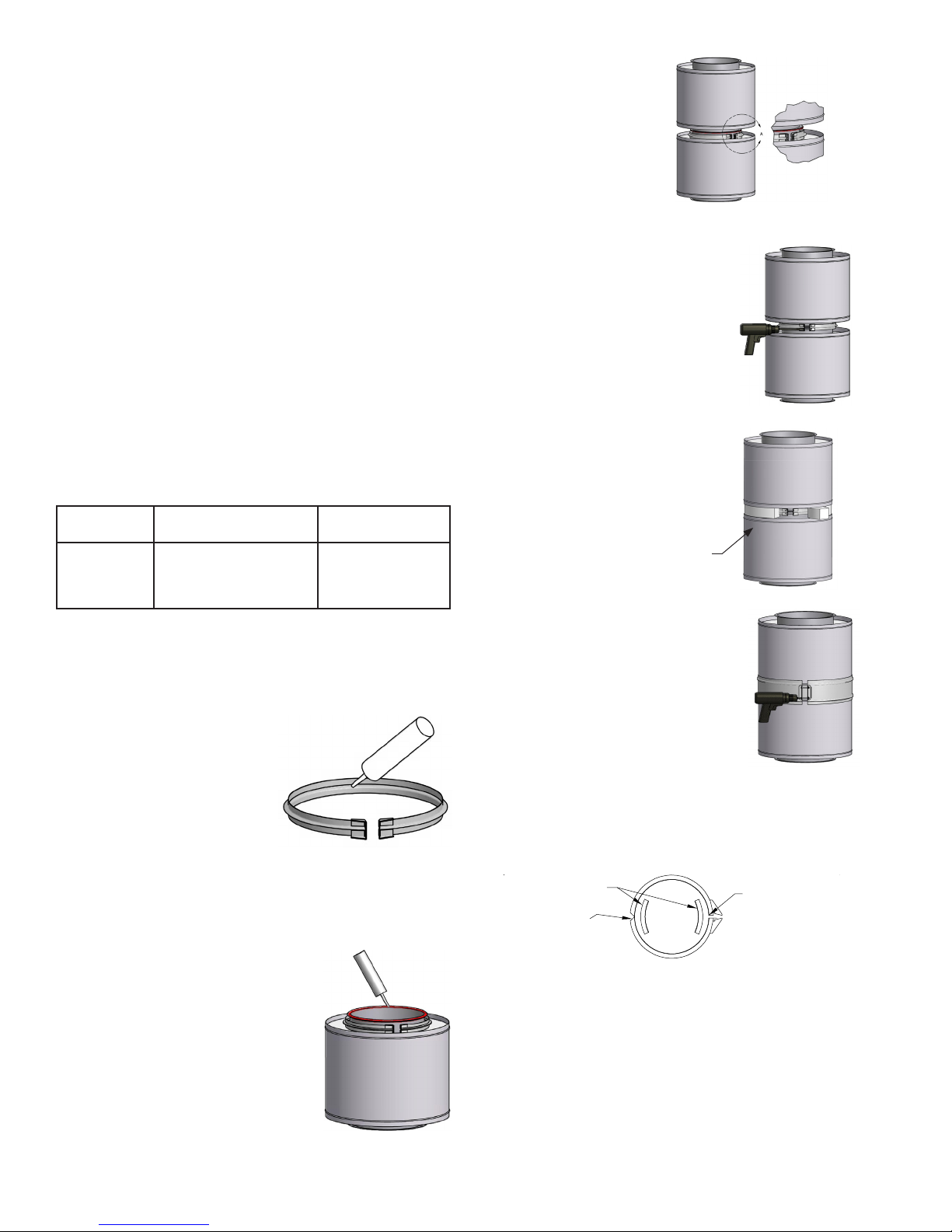
JOINT ASSEMBLY
The Model PIC/IPIC joint sealing system is designed for quick and
easy installation. For most applications follow Steps 1 through 6.
(For High Pressure applications, see additional steps.)
STEP 1
Fill the channel of the ange band with
the proper sealant and install below ange
of rst pipe section.
NOTE: Sealant is to be supplied
by Metal-Fab. See TABLE 3
on Page 23 for number of
tubes per joint.
CAUTION: THE USE OF ANY OTHER SEALANT ON THE
FLANGE SURFACE WILL NEGATE ALL LISTINGS OF THE
PRODUCT AND IMPAIR THE SEALING EFFECTIVENESS.
STEP 2
Apply a continuous bead of proper sealant
to one of the anges to be joined.
NOTE: For gas temperatures up to 600ºF,
use P077 sealant.
For gas temperatures over 600ºF,
use P071 sealant.
For high pressure applications,
including ALL engine or
turbine exhaust applications, use P071 sealant.
STEP 3
Join the two anged ends of
the pipe sections.
STEP 4
Install the ange band around the anges.
NOTE: Do not locate V-Clamp
hardware at the bottom side
of horizontal duct joints.
When installing ange band, tap lightly with
hammer around periphery of band while
tightening draw screws. This helps to align
anges for the best seal. Do not overtighten
draw screws.
NOTE: Allow sealant to cure 24 hours
before operating appliances.
STEP 5
(IPIC Installations Only)
Pack the void between inner and outer
walls with insulation strips.
INSULATION STRIPS (PROVIDED)
STEP 6
Secure the outer casing with the closure
band.
When system is installed outdoors, the
upper side (upper half in the horizontal
position) of the closure band bead
should be sealed with P077 sealant to make
the casing watertight.
For all ENGINE EXHAUST and other HIGH PRESSURE
applications, perform Steps 1 through 3 above, then:
4. Install the seal clip(s) on the anges 6”, 8” and 10” only.
(See TABLE 4).
Note: 6” & 8” require two seal clips located as shown.
SEAL CLIPS
SEAL CLIP BETWEEN
FLANGE AND FLANGE
BAND NOTCH
SEAL CLIP BETWEEN
FLANGE AND
FLANGE BAND BOLT
CONNECTION
5. Install the ange band around the anges making sure
the joint is located so the seal clip overlaps both edges
of the joint.
6. Fill the space behind the ange band on both sides of
the ange with P071 pressure sealant (See FIG. 3).
7. Pack void between inner and outer walls with insulation
strips for IPIC installations.
8. Secure the outer casing with the closure band. Apply
sealant to closure band for exterior applications only.
See JOINT ASSEMBLY and FIG. 3 for llustrations of the
joining process and nished joint.
4
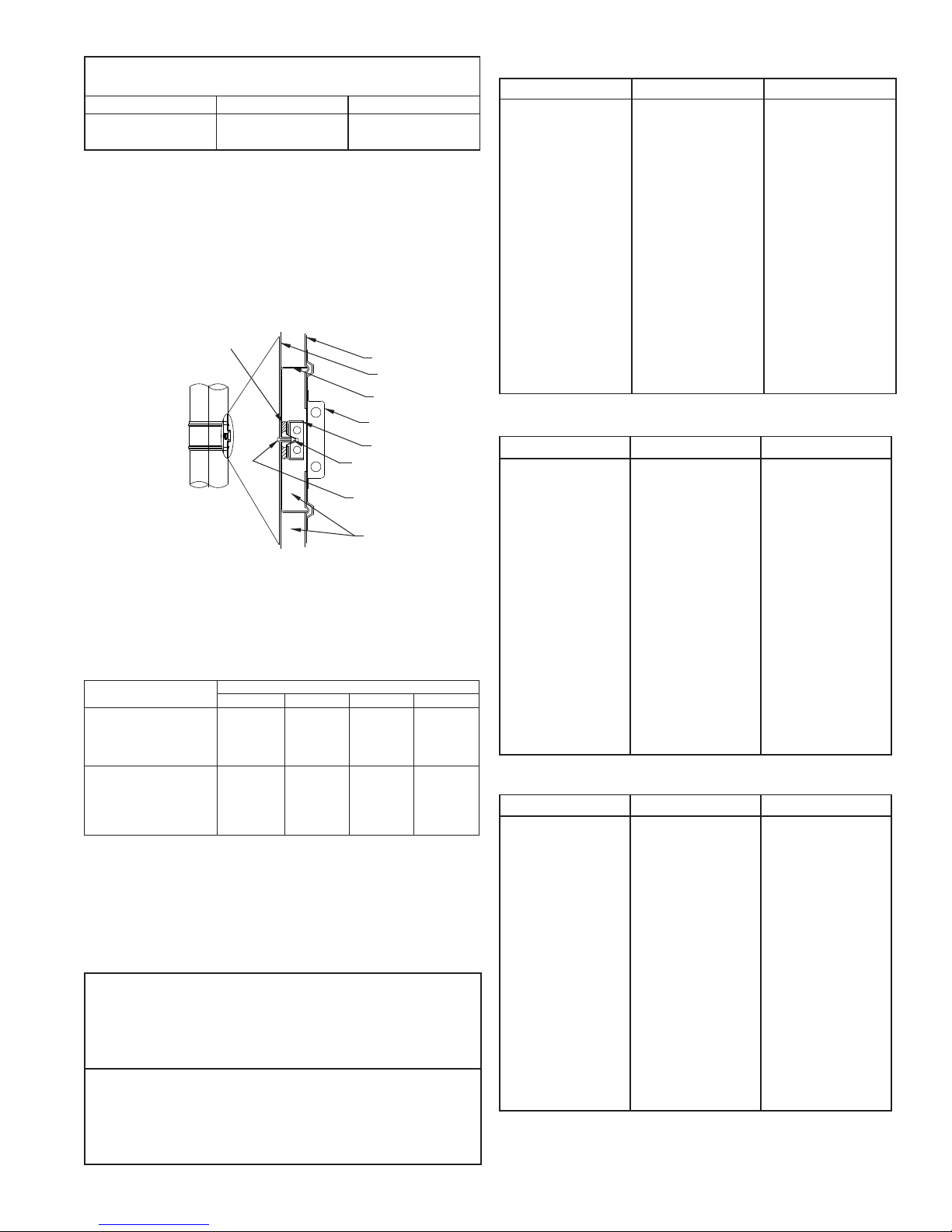
TABLE 4 - SEAL CLIPS REQUIRED PER JOINT
FOR PRESSURE SEALS
Pipe Diameter No. of Clips Part No.
6”-8” 2 SCK6-8*
10” 1 SCK10
*SCK6-8 contians 2 seal clips
Properly sealed joints are gas tight and resistant to water, oil
solvents and acids (except hydrouoric).
IMPORTANT: P071 Sealant must cure at operating
temperatures above 500°F at a minimum
3-hr curing time.
FIG. 3 – ASSEMBLED MODEL PIC JOINT
APPLY SEALANT BETWEEN
FLUE AND FLANGE BAND (SEE
STEP 6 ENGINE EXHAUST)
OUTER PIPE
INNER PIPE
SPACER CLIP
OUTER CLOSURE BAND
FLANGE BAND
APPLY SEALANT TO FLANGE
BAND (SEE STEP 1 JOINT
ASSY.)
APPLY SEALANT TO INNER
PIPE FLANGES (SEE STEP
2 JOINT ASSY.)
INSULATION (IPIC ONLY)
SUPPORT LIMITS - SUPPORT SPACING
TABLE 5 provides the maximum vertical distances between
supports for various support types. Using these supports, the
maximum installed chimney height is 200 feet (60.96m).
TABLE 5
Support Method Maximum Supported Height (meter)
Wall Support
Pier or Appliance Outlet
Plate Support Assembly
Roof Support Assembly
Stack Support Assembly
Fan Adapter Plate 6”-36” dia.
PIC IPIC-1 IPIC-2 IPIC-4
40’ (12.19m)
100’ (30.48m)
100’ (30.48m)
30’ (9.1m)
100’ (30.48m)
20’ (6m)
34’ (10.4m)
85’ (25.9m)
85’ (25.9m)
25’ (7.6m)
100’ (30.48m)
6”-28” dia.
20’ (6m)
30”-36” dia.
15’ (4.6m)
30’ (9.1m)
75’ (22.9m)
75’ (22.9m)
22’ (6.7m)
100’ (30.48m)
6”-26” dia.
20’ (6m)
28”-36” dia.
15’ (4.6m)
29’ (8.8m)
73’(22.3m)
73’(22.3m)
22’ (6.7m)
100’ (30.48m)
6”-18” dia.
20’ (6m)
20”-26” dia.
15’ (4.6m)
28”-36” dia.
10’ (3m)
GUIDE SPACING
TABLE 6 provides maximum distance between guides for
chimney installed inside building. (For exterior installations, See
TABLE 7 and FIG. 37.) These numbers represent ALL diameters
and vary depending on the amount of insulation.
TABLE 6
Maximum Unsupported Horizontal Spacing:
PIC
IPIC-1
IPIC-2
IPIC-4
Maximum Unsupported Vertical Spacing Below Roof Line:
PIC
IPIC-1
IPIC-2
IPIC-4
12’-6” (3.8m)
10’ (3.1m)
9’ (2.7m)
9’ (2.7m)
25’ (7.6m)
21’ (6.4m)
19’ (5.8m)
18’ (5.5m)
TABLE 7 - PIC & IPIC-1 GUYING REQUIREMENTS
Pipe Diameter “A” “B”
6”
8”
10”
12”
14”
16”
18”
20”
22”
24”
26”
28”
30”
32”
34”
36”
38”
40”
42”
44”
46”
48”
17’ 0” (5.18m)
17’ 6” (5.33m)
18’ 6” (5.64m)
20’ 0” (6.10m)
21’ 0” (6.40m)
22’ 0” (6.71m)
23’ 0” (7.01m)
24’ 0” (7.32m)
24’ 6” (7.47m)
25’ 0” (7.62m)
26’ 0” (7.92m)
27’ 0” (8.23m)
27’ 0” (8.23m)
28’ 6” (8.69m)
29’ 0” (8.84m)
30’ 0” (9.14m)
30’ 6” (9.30m)
31’ 0” (9.45m)
32’ 0” (9.75m)
32’ 6” (9.91m)
33’ 6” (10.21m)
34’ 6” (10.52m)
8’ 6” (2.59m)
8’ 9” (2.67m)
9’ 3” (2.82m)
10’ 0” (3.05m)
10’ 6” (3.20m)
11’ 0” (3.35m)
11’ 6” (3.51m)
12’ 0” (3.66m)
12’ 3” (3.73m)
12’ 6” (3.81m)
13’ 0” (3.96m)
13’ 6” (4.11m)
13’ 6” (4.11m)
14’ 3” (4.34m)
13’ 6” (4.11m)
15’ 0” (4.57m)
15’ 3” (4.64m)
15’ 6” (4.72m)
16’ 0” (4.88m)
16’ 3” (4.95m)
16’ 9” (5.10m)
17’ 3” (5.26m)
TABLE 7 - IPIC-2 GUYING REQUIREMENTS
Pipe Diameter “A” “B”
10”
12”
14”
16”
18”
20”
22”
24”
26”
28”
30”
32”
34”
36”
38”
40”
42”
44”
46”
48”
6”
8”
10’ 6” (3.20m)
12’ 0” (3.66m)
13’ 3” (4.04m)
14’ 6” (4.42m)
15’ 11” (4.85m)
17’ 0” (5.18m)
18’ 3” (5.56m)
19’ 6” (5.94m)
20’ 2” (6.15m)
20’ 9” (6.32m)
21’ 5” (6.53m)
22’ 1” (6.73m)
22’ 8” (6.91m)
23’ 4” (7.11m)
24’ 0” (7.32m)
24’ 7” (7.49m)
24’ 7” (7.49m)
24’ 7” (7.49m)
24’ 7” (7.49m)
24’ 7” (7.49m)
24’ 7” (7.49m)
24’ 7” (7.49m)
7’ 11” (2.41m)
8’ 5” (2.57m)
8’ 11” (2.72m)
9’ 5” (2.87m)
9’ 11” (3.02m)
10’ 6” (3.20m)
11’ 0” (3.35m)
11’ 6” (3.51m)
11’ 10” (3.61m)
12’ 3” (3.73m)
12’ 6” (3.81m)
13’ 1” (3.99m)
13’ 5” (4.09m)
13’ 10” (4.22m)
14’ 3” (4.34m)
14’ 7” (4.45m)
14’ 11” (4.55m)
15’ 3” (4.64m)
15’ 9” (4.80m)
16’ 3” (4.95m)
16’ 6” (5.03m)
17’ 0” (5.18m)
TABLE 7 - IPIC-4 GUYING REQUIREMENTS
Pipe Diameter “A” “B”
6”
8”
10”
12”
14”
16”
18”
20”
22”
24”
26”
28”
30”
32”
34”
36”
38”
40”
42”
44”
46”
48”
8’ 3” (2.51m)
9’ 7” (2.92m)
10’ 9” (3.28m)
11’ 11” (3.63m)
13’ 2” (4.01m)
14’ 2” (4.32m)
15’ 4” (4.67m)
16’ 4” (4.98m)
17’ 0” (5.18m)
17’ 7” (5.36m)
18’ 2” (5.54m)
18’ 9” (5.72m)
19’ 4” (5.89m)
19’ 11” (6.07m)
20’ 6” (6.25m)
21’ 0” (6.40m)
21’ 0” (6.40m)
21’ 0” (6.40m)
21’ 0” (6.40m)
21’ 0” (6.40m)
21’ 0” (6.40m)
21’ 0” (6.40m)
6’ 8” (2.03m)
7’ 3” (2.21m)
7’ 9” (2.36m)
8’ 4” (2.54m)
8’ 11” (2.71m)
9’ 6” (2.90m)
10’ 1” (3.07m)
10’ 8” (3.25m)
11’ 0” (3.35m)
11’ 6” (3.51m)
11’ 10” (3.61m)
12’ 4” (3.76m)
12’ 8” (3.86m)
13’ 2” (4.01m)
13’ 6” (4.11m)
13’ 11” (4.24m)
14’ 3” (4.34m)
14’ 8” (4.47m)
15’ 2” (4.62m)
15’ 8” (4.78m)
16’ 0” (4.88m)
16’ 5” (5.00m)
5
CHIMNEY ABOVE ROOF
When chimney is extended above rooine, special consideration
should be given to support and guying requirements. Use of a
standard or variable pitch ashing requires that the chimney be
stabilized to resist side loading. FIG. 4 and 8 depict methods
of protecting a ashing from side loads using a full angle ring
or plate support. Ventilated thimble and roof support assemblies
include lateral support rings, and additional guidance at the
rooine is not required.
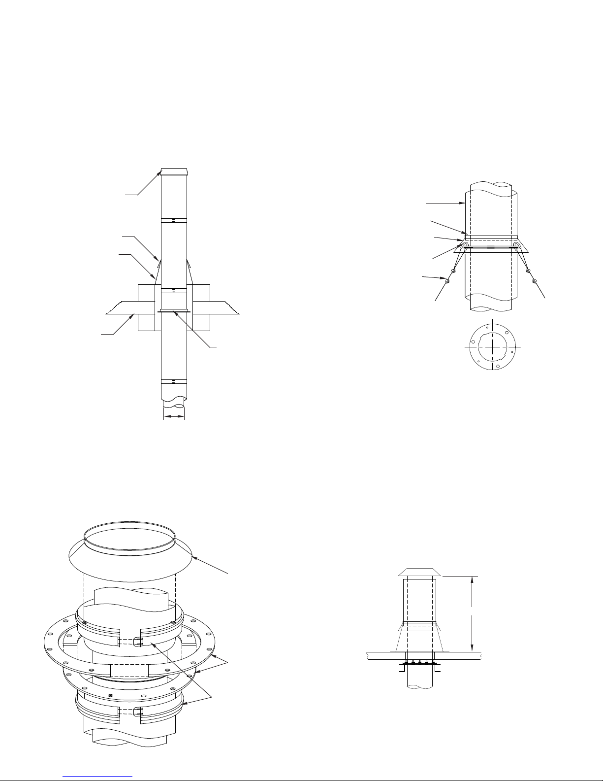
FIG. 4 – FULL ANGLE RING FOR LATERAL SUPPORT
The guy ring consists of four (4) identical half rings with hardware
to secure them together, two (2) half closure bands and a storm
collar (FIG. 5). Select the joint where the guy ring is to be located
and assemble the inner wall joint (Steps 1 to 6 under JOINT
ASSEMBLY on Page 4). Sandwich the ange band between the
guy rings with the joints of the top and bottom rings 90º apart and
the cutouts aligned. Clamp the guy ring with the nuts and bolts
provided. Install the half closure bands above and below the guy
ring, then attach the cables or braces (See FIG. 6). Install the
storm collar above the upper half closure. The collar should be
caulked with sealant to prevent water entry.
FIG. 6 – GUY RING CABLE ATTACHMENT
CLOSURE RING
STORM COLLAR
FLASHING
ROOF
ANGLE RING MUST BE
USED WITH FLASHING
PIPE DIAMETER
GUY RING (GR)
Chimneys that extend above the roof, or are installed in severe
weather regions, may require a guy ring (GR) to enable the
chimney to resist wind loads. The guy ring is connected to
the building or other structure by means of cables or braces
TABLE 6 provides the spacing between guy rings and freestand
height for Model PIC/IPIC Chimney.
FIG. 5 - PIC/IPIC GUY RING, EXPLODED VIEW
CASING
APPLY SEALANT BETWEEN
COLLAR & CASING
STORM COLLAR
CABLE THIMBLE
CABLE CLAMPS
NOTE: Align large holes on
Guy Ring Halves during
assembly.
GUY RINGS DRILLED FOR
3 OR MORE CABLES
NOTE: Cable, cable clamps and cable thimble supplied by
others.
Cable or braces (supplied by the installer) should be slightly loose
to allow for thermal expansion for single guy ring installations
(FIG. 8) or be equipped with tensioning springs on multiple
guy ring installations (FIG. 9). To reduce the effect of thermal
expansion on the guy cables or braces, a xed-point support
(plate or wall support assembly) may be installed immediately
below the rooine as shown in FIG. 8.
NOTE: When chimney is installed outside building, adjacent
to wall, spacing between guides is equal to dimension “A”
in TABLE 6 (Refer to FIG. 34 on Page 15).
STORM COLLAR
GUY RING
HALF RINGS (4 PCS.)
HALF CLOSURE
BANDS (2 PCS.)
FIG. 7 – MAXIMUM FREE-STANDING HEIGHT ABOVE ROOF
“B”
NOTE: See TABLE 7 for “B” dimensions.
6
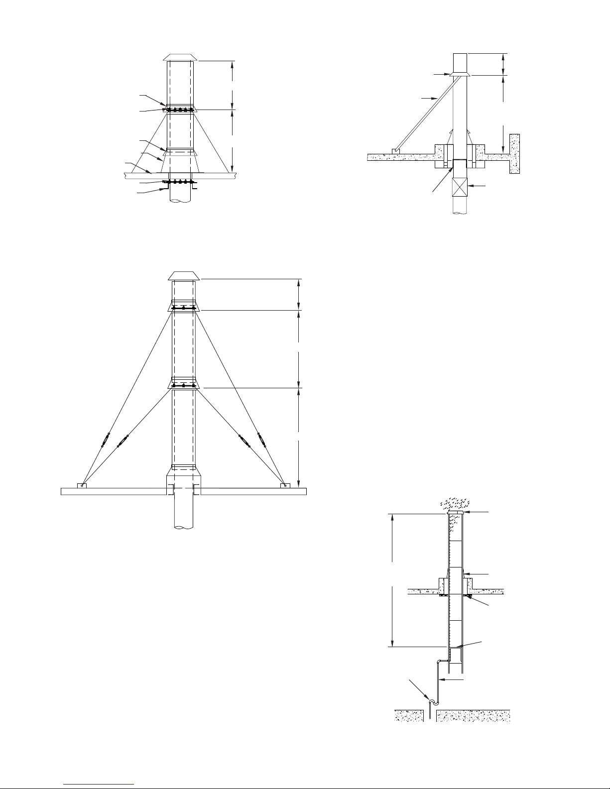
FIG. 8 – GUYING FOR SINGLE SECTION
STORM COLLAR
GUY RING
FIG. 10 – HEIGHT LIMITS FOR RIGID GUYING
“B”
“B”
(ON INSIDE OF COLLAR)
USE RIGID GUYS IF
CHIMNEY IS CLOSE TO
GUY RING
OUTSIDE WALL
MAXIMUM
SPACING
5 FT.
STORM COLLAR
FLASHING
ROOF
PLATE SUPPORT
SUPPORT STEEL
(BY INSTALLER)
“A”
NOTE: See TABLE 7 for “A” and “B” dimensions.
FIG. 9 – CHIMNEY GUYING REQUIREMENTS
A PLATE SUPPORT OR WALL
SUPPORT ASSEMBLY MUST BE
USED AT ROOF LEVEL WHEN
RIGID GUYING IS USED
EXPANSION JOINT
OR BELLOWS JOINT
NOTE: See TABLE 7 for “B” dimensions.
PIPE LENGTHS (9, 18, 30, 42)
Model PIC/IPIC pipe is available in 4 standard lengths: 9” (229),
“B”
18” (457), 30” (762) and 42” (1067). Pipe sections are joined,
using appropriate sealant, to make up desired length of run.
These sections may be modied by use of nipples or couplings
to accept auxiliary equipment such as temperature probes or
smoke monitors. Consult factory or your local representative to
obtain information regarding such modications.
“A”
DRAIN SECTION (DS)
A drain section is a special variation of an 18” (457) pipe length
with provision to drain rain or condensate from the chimney. The
pipe ue is equipped with an annular catch ring and a 1” (25)
NPT nipple extending through the casing for attachment of drain
piping. The drain piping should include a water leg of a height
at least equal to the maximum expected operating pressure at
“A”
the appliance outlet to avoid allowing ue gases to vent through
the drain. Drain section should be installed indoors to prevent
freezing (See FIG. 11).
NOTE: See TABLE 7 for “A” and “B” dimensions.
Cables should be spaced at or near 120º intervals (3 cables)
or 90º (4 cables). Rigid bracing requires two (2) braces spaced
between 60º and 150º apart. Maximum spacing between the
xed support and the guy ring is 5 feet when rigid bracing is used
(See FIG. 10).
FIG. 11 – DRAIN SECTION INSTALLATION
6 PIPE
DIAMETERS
OR MORE
TRAP HEIGHT EQUAL TO
MAX. APPLIANCE OUTLET
PRESSURE
1” PIPING
7
CLOSURE RING
FLASHING AND
STORM COLLAR
FULL RING GUIDE
DRAIN SECTION
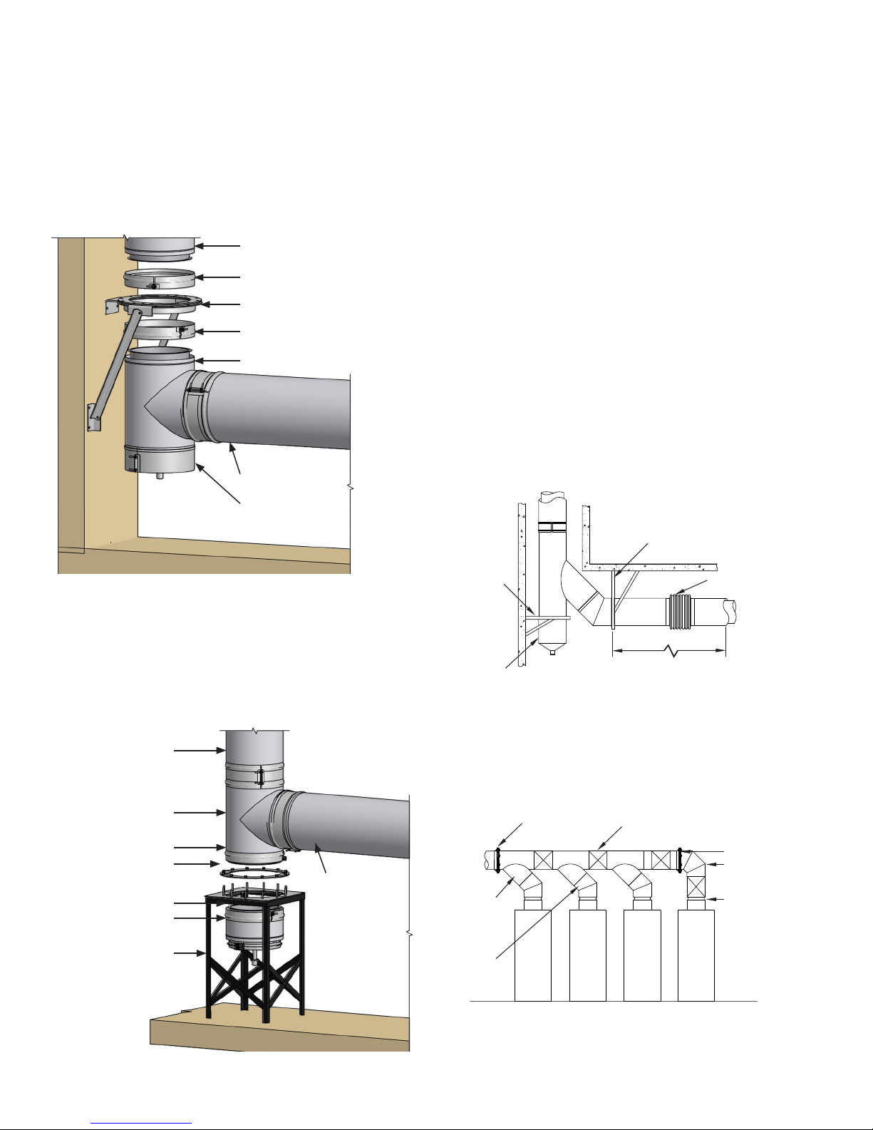
STANDARD 90º TEE (90MT)
The 90º Manifold Tee (90MT) may be used to connect horizontal
to vertical when a cleanout access or drain is desired. If more
than 1/4” (6) of thermal expansion is expected between the
tee and the next xed support point (the appliance outlet, for
example), the tee should be protected from bending moments
by use of an expansion joint or bellows joint. See the sections on
those ttings for additional information about compensation for
thermal expansion.
FIG. 12 – SUSPENDED TEE
PIPE RISER
HALF CLOSURE BAND
WALL SUPPORT ASSEMBLY
HALF CLOSURE BAND
TEE AT BASE OF RISER
DRAIN TEE CAP (TC), CLEANOUT CAP
The unused port of a tee must be closed to prevent leakage of
ue gases. A drain tee cap is used to close the tee and drain
condensation or rainwater when the tee is installed at the base of
a rise. When the tee is to be used for cleanout or access purpose
only, a cleanout cap (TCN) is recommended. Both the drain tee
cap and the cleanout cap are equipped with closures, which
serve the dual purpose of maintaining the double wall clearance
to combustible and giving the cap a nished appearance.
The drain tee cap’s drain nipple must be connected to a suitable
disposal point. Any rain entering the chimney will wash down
and remove any combustion residue from the chimney ue. The
resulting efuent may be corrosive. The tee cap must be sealed
at the connection to the tee using the appropriate sealant for the
application. This will assure that moisture will drain through the
drain nipple, as intended.
45º MANIFOLD TEE (45MT), DOUBLE LATERAL (DL)
For systems where minimizing ow resistance is desirable
or critical, a manifold tee having a 45º entrance to the trunk
is available. When used to make 90º turns, an additional 45º
elbow is required. It is particularly important to isolate the 45º
manifold tee from the effects of thermal expansion. This isolation
is typically accomplished by the use of a 2-axis support (See
FIG. 14). Otherwise, the installation details and precautions are
similar to those for the 90º manifold tee.
PIPE SECTION
DRAIN TEE CAP
When a tee is used at the base of a riser, the preferred location
for support is above the tee, thus suspending the tee (FIG. 12). If
it is not possible to suspend the tee, it may be supported from the
base of the tee (FIG. 13). When this type of support is necessary,
access to the drain cap may be hindered. A drain bucket should
be used under the tee to allow access to the tee cap.
FIG. 13 – BASE SUPPORTED TEE
PIPE RISER
TEE
HALF CLOSURE BAND
CLAMP RING
(SEE NOTE BELOW)
PIPE SECTION
FIG. 14 - TWO-AXIS SUPPORT METHOD
PLATE SUPPORT ATTACHED
TO BUILDING STRUCTURE
WALL SUPPORT
ASSEMBLY
DRAIN BUCKET
MORE THAN 1/4” THERMAL
EXPANSION EXPECTED
BELLOWS JOINT OR
EXPANSION JOINT
MULTIPLE APPLIANCE BREECHINGS (HEADERS)
When 90º or 45º manifold tees are used to manifold multiple
appliances together, it is important to make provisions for
expansion of the manifold. An expansion joint should be installed
between tees (See FIG. 15). The manifold must be supported
properly by means of plate supports or wall support assemblies
arranged to protect the tees from bending forces.
FIG. 15 – LATERAL TEE MANIFOLD
PLATE SUPPORT
ADJUSTABLE LENGTHS
OR BELLOWS JOINT
PLATE SUPPORT
90° ELBOW
HALF CLOSURE BAND
DRAIN BUCKET
STRUCTURAL STEEL
STAND (BY OTHERS)
45° MANIFOLD
TEE
45° FIXED
ELBOW
OUTLET
30º, 45º OR 90º FIXED ELBOWS (30L) - (45L) - (90L)
Elbows are not designed to resist bending loads and must be
protected by structural reinforcement. FIG. 16 depicts some
alternative methods for protection of elbows. Elbows may be
8
 Loading...