

Page 1
MMetalfab, Inc.
Dry Solids Processing Equipment
P.O. BOX 9, PRICES SWITCH ROAD, VERNON, NEW JERSEY 07462 ♦ 973-764-2000 ♦ FAX # 973-764-0272
INSTRUCTIONS FOR OPERATION & MAINTENANCE
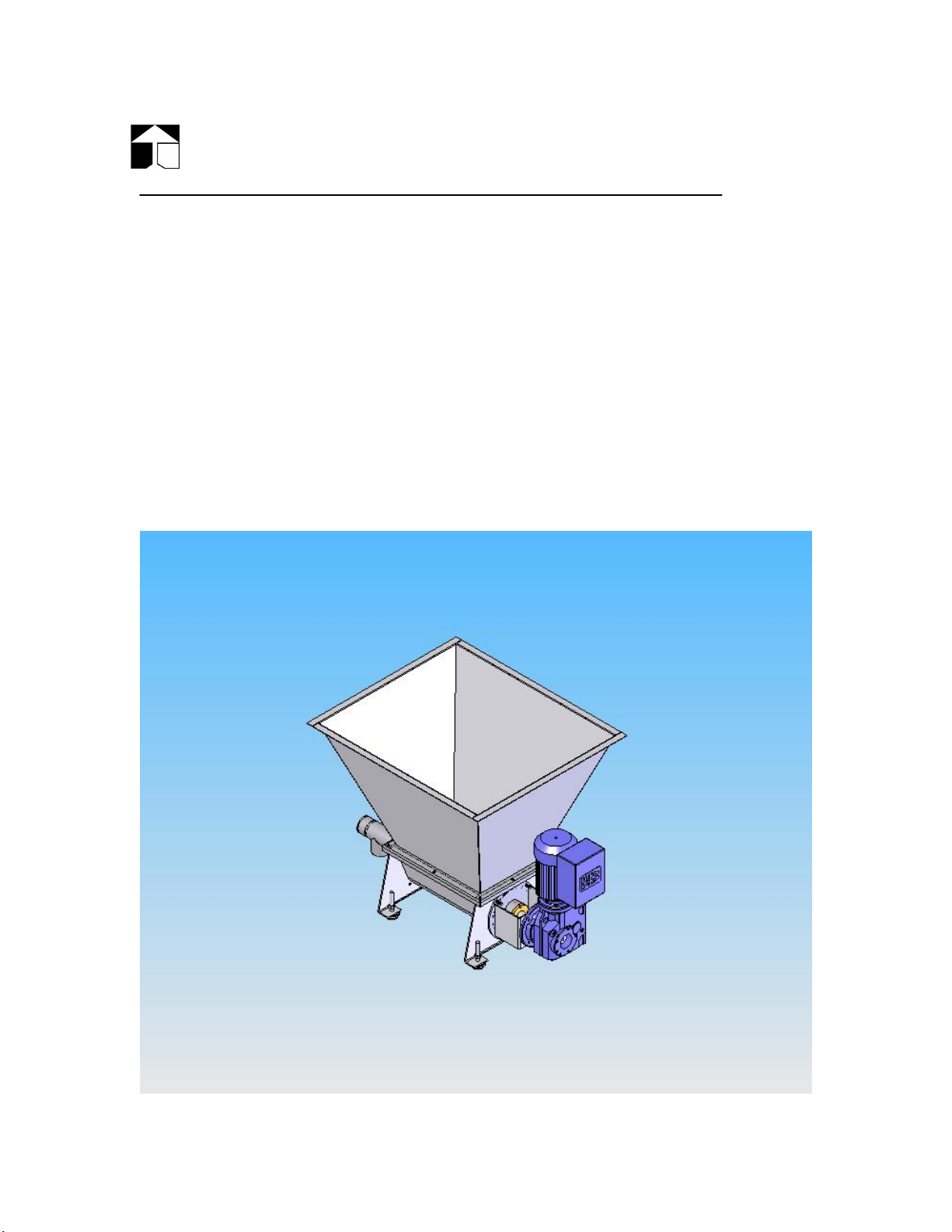
MetaTech MT-X-XXX Series
VOLUMETRIC SCREW FEEDER
Fig A.
Page 2

The MetaTech Feeder is a simple, rugged and accurate Volumetric Feeder used
for the dependable metering of dry solid materials into a variety of
manufacturing processes. It consists of a trough assembly. a hopper in various
capacities, a GearMotor Drive (which is available in many input power
configurations and ratios), a Metering Screw and Tube in sizes and styles to fit
the application. The metering screw is coupled to the variable speed drive,
either AC with a VFD or DC with an SCR; all mounted on the trough assembly
with isolation feet mounts or mounted to a custom frame.
The steep, sloped hopper, with its large rectangular outlet, allows for material
flow to the metering screw. The metering screw consists of three spiral wraps,
the largest being the agitator which assists the motion of produce within the
trough, the mid sized The function of this screw is to keep the material in motion
and also "condition" the material to a constant density while insuring complete
filling of the metering screw flights. Hence, accuracy is maintained while rates
are varied by screw speed changes.
Installation
The MetaTech Feeder is shipped complete and ready for operation. For
enhanced safety, the unit should be bolted in place, absent this there are four
(4) levelers positioned under the base which are equipped with rubber pads.
Room should be provided at the discharge end to allow for screw removal.
Normally, 20" clearance is sufficient.
Electrical Requirements
Standard units are provided with AC Inverter Duty Drives which can have their
own VFD controllers mounted integral to the motor housing or stand alone
VFDÅfs of the Customer specification. Typical VFDÅfs capable of varying output
frequency from 0 to 100 Hz, minimum operation at 5 hz is recommended for
adequate cooling. The controller may be mounted at the Feeder location or
remotely. SEW Eurodrive Inverter Manual and DC SCR Control Manuals are
attached at the end of this manual. All standard motors are TEFC (totally
enclosed, fan cooled), severe heat applications may require TEBC (blower
cooled) models which will require a separate power input for the blower.
Inverter Duty Motors are dual voltage 230/460 three phase. Inverter Drives
(VFDÅfs) are 230 vac OR 460 vac models special applications for single phase
input power can be accommodated as can 380vac, 575vac and 50Hz models;
contact Metalfab Inc. for these special applications and consult Inverter Drive
Manuals and for specifications. For amperage considerations 460/3 motors will
draw 1 amp per Hp and should be equipped with supply capacity 2X this nominal
Page 3

amperage for inrush consideration. 230/3 models will draw exactly double the
460/3 ratings.
DC Motors are available with field windings (shunt wound) or permanent
magnet, both are available in 90vdc (std _ Hp) and 180vdc (std 1Hp) armatures.
DC motor speed is modulated by varying the armature voltage from 0 to max,
15% speed should be considered the min speed for motor cooling considerations
Operation
After the Feeder is in place and wired, it is ready for operation. Units equipped
with electrically variable speed drives can have their speed adjusted at anytime,
i.e., with the unit stopped or in motion. The dial provides for setting screw
speeds to 1 part in 100. Speed is increased by turning the potentiometer in
clockwise rotation. Optional digital keypads for Local/Remote operation are
available, again consult the feeder specification and pricing sheets for options.
The hopper should be filled with the feed material and the potentiometer should
be set to 50%. The unit should be allowed to run for 5 minutes before a 1
minute sample is collected and weighed. It is suggested that 5 or more samples
be taken to assure the Feeder is operating properly. Once the feed rate is
known at 50%, the required rate may then be obtained by proper speed change.
The drive and, therefore, the feed rates are linear, hence, at setting of 50% the
Feeder will be operating at approximately half capacity. As an example, if at a
50% setting a 20#/minute rate is achieved and a 10#/minute rate is desired,
change the setting to 25% and a 10#/minute rate will be delivered. Take
samples at 3 or 4 settings and plot a graph, setting versus rate. From this
graph, any feed rate may be selected. This calibration should be done at the
end user application as material bulk density and condition due to prior steps in
the process will have an impact on the ÅgActual Discharge RatesÅh, approximate
rates are listed on the drawing on the final pages in the spare parts section of
this manual.
Warning: Keep hands clear of all moving parts. Serious injury can occur.
Page 4

Standard Inverter Duty Gearmotor fig B.
The hopper may be equipped with a pneumatically or electrically operated
vibrator if the feed product requires an assist to promote flow. The hopper is
also equipped with a baffle when a vibrator is used. The amount of vibration
should be minimal, just enough to promote flow. The vibrations of the
pneumatic vibrator may be adjusted by changing the P.S.I. setting (pressure
regulator, filter, gauge, etc., by customer), but should not exceed a maximum
pressure of 80 P.S.I. For electric vibrators, the vibrations may be adjusted by
changing the alignment of the centerlines of the eccentric weights, consult the
vibrator manual for proper instructions. In all applications, the vibrator should
be controlled such that it only operates while the feeder is operating. Operation
of the vibrator without an established discharge from the feeder may cause the
material to pack in the trough and/or hopper.
The closer you align the centerlines of the two (2) OUTER weights with the
centerlines of the two (2) INNER weights, you are INCREASING the force. The
further you misalign the referenced centerlines, the more your DECREASE the
force. If the centerlines of all four (4) weights are completely aligned, you will
Page 5

develop the maximum force available. Under all conditions, the OUTER weights
should be a mirror image of each other and the INNER weights should be a
mirror image of each other so that the imbalance of the vibrator is uniform on
both ends of the vibrator motor shaft.
Any other arrangement could cause damage to the hopper, welds and
the feeder in general.
Maintenance Fig C.
The MT Series Feeders are reasonably maintenance free. Listed below are
suggested maintenance schedules:
1. The Front Bushing supports the discharge end of the metering screw and
is retained by a bolt at the extreme end of the discharge tube. This
bushing is sealed to the Tube with an O-Ring, the bushing has a blind
hole so that zero leakage from the discharge bushing can be expected.
The bushing will wear over time and should be replaced as required.
Page 6

Wear rate is dependent on material being discharged and other factors,
including bulk density, particle size, hardness and discharge rate. Sealed
flange bearings are available as an option, these bearings typically have a
zerk style grease fitting and should be lubricated every 6 months.
2. The rear of the metering screw is supported by the bearings in the
gearbox assembly and lubricated via the gearbox oil (see #4 below). The
hollow shaft gearbox aligns and supports the shaft and retains it via a
7/16 bolt. .
3. Rear seal packing is a standard Teflon Braided Packing Rope. If any
leakage is observed, the packing pusher (bronze unit under motor mount)
should be tightened. Periodically the Teflon Rope will require
replacement, again the actual schedule being determined by type of
material and amount of use.
4. The standard speed reducer is oil lubricated and should not be re
lubricated for up to (5) years of service.
5. The Drive Motors have lifetime-lubed bearings, which give years of
service. If bearings fail, a competent motor repair shop must replace
them. Brushes on DC Drives should be checked for wear every (6)
months of continuous service.
6. When handling highly abrasive materials, the screw should be checked
periodically for wear.
7. When units are equipped with a vibrator assembly it is important that the
unit is not operated with an empty hopper as this may cause cracks
around or near the vibrator mounts or at the welded corners of the
hopper. Check welds near the vibrator periodically (6 months) for
evidence of cracks, should cracks be found, corrective action is to
determine how to prevent the vibrator from operating with an empty
hopper.
8. The trough end plates are secured with (4) nuts on studs, they are sealed
to the trough with a captured o-ring seal, ensure the o-ring cord stock is
in the groove before tightening the nuts. O-ring face seals ensure zero
leakage of dry materials at the trough ends.
9. Trough and Hopper covers are available with dust sock and vent ports for
the capture of fugitive dust and to prevent air lock while refilling the
hopper.
Page 7

Fig D.
Disassembly
Warning: Motor must be electrically Locked-out before any work is
performed.
The MT-X-XXX Series Feeder is easily disassembled for cleaning, changing of
screws, or maintenance purposes. To remove the discharge tube:
1. Remove the four (4) nuts and pull the discharge tube forward until it
disengages the screw.
To remove the screw the tube must be removed as indicated above then:
Page 8

1. Remove plastic end cap on gearbox shaft center, under the cap is a 7/16 bolt
which retains the screw to the gearbox, remove this bolt and the screw will
easily slide forward and out of the trough section.
2. Loosen the bronze pusher and remove it from the packing box to remove
and replace the packing rope with three rings of Teflon braid.
The hopper may be removed by undoing the bolts and lifting vertically off the
trough assembly. The low level switch (if provided) is threaded into the pipe
coupling on the top of the Hopper assembly, please see the Babbit LS-2000 Level
Sensor Literature for specific wiring information.
Re-assemble by reversing the above procedures.
When inquiring about any feeder, always refer to the Serial Number
stamped on the Metalfab nameplate J-XXXXXXX
Fig E.
Page 9

MT-X-XXXX
FEEDER SPARE PARTS LIST
Fig F.
ITEM DESCRIPTION P/N
1. FRONT END BUSHING S/N-BUSH
2. REAR SEAL PUSHER S/N-PUSH
3. REAR SEAL (TEFLON BRAID) TEFLON PACKING
4. DUST SOCK (OPTIONAL) DUST-DIA
Page 10

5. LEVEL SENSOR (OPTIONAL) LS-2000
6. FEED SCREW * MT-X-SCREW
7. FEED TUBE* MT-X-TUBE
8. MOTOR* SPECIFY TYPE
9. GEARBOX* KAZ37AM6
*ITEMS MARKED WITH ASTERISK ARE PROVIDED FOR
REFERENCE ONLY. THESE ITEMS WILL REQUIRE
REFERENCE TO SERIAL NUMBER, MODEL, SIZE, RATIO,
INPUT POWER AS REQUIRED.
Metalfab Service
Metalfab, Inc.
Prices Switch Road
P.O. Box 9
Vernon, NJ 07462
Phone (973) 764-2000 * Fax (973) 764-0272
Email: metalfab@metalfabinc.com
 Loading...