

Page 1
INSTALLATION AND
MAINTENANCE
PIC
INSTRUCTIONS
IPIC
MODEL PIC/IPIC
CHIMNEY AND VENTS
A MAJOR CAUSE OF CHIMNEY RELATED FIRES IS
FAILURE TO MAINTAIN REQUIRED CLEARANCES
(air spaces) TO COMBUSTIBLE MATERIALS. IT IS OF
UTMOST IMPORTANCE THAT CHIMNEY BE INSTALLED
ONLY IN ACCORDANCE WITH THESE INSTRUCTIONS.
This symbol on the nameplate
means this product is listed by
Underwriters Laboratories Inc.
and by Underwriters
Laboratories of Canada
IMPORTANT: DO NOT INSTALL CHIMNEY WITHOUT
FIRST READING THESE INSTRUCTIONS
VERY CAREFULLY.
Metal-Fab’s Model PIC/IPIC Chimney has been fully tested and listed by Underwriters Laboratories, Inc.
and Underwriters Laboratories of Canada.
Chimneys installed in accordance with these installation instructions will comply with national safety
standards and building codes.
This booklet contains complete information on details concerning dimensions, installation, clearances to
combustibles, and use of non-combustible enclosures. For any additional construction information, refer
to Model PIC/IPIC Design Manual - L1690.
• BREECHING APPLICATIONS
• BOILER EXHAUST APPLICATIONS
• ENGINE/TURBINE EXHAUST APPLICATIONS
METAL-FAB, INC. • P.O. BOX 1138, WICHITA, KANSAS 67201 • (316)943-2351
Page 2

GENERAL INFORMATION
LISTINGS
Metal-Fab Model PIC/IPIC Chimney is “listed” by Underwriters Laboratories, Inc (UL File No. MH8251) as “Building Heating Appliance
Chimney” for continuous operation at 1000ºF and intermittent operation (less than one hour) at 1400ºF. For higher temperature
applications, it is also “listed” as “1400ºF Factory Built Chimney” for continuous operation at 1400ºF and intermittent operation at
1800ºF. PIC/IPIC Chimney is “listed” by Underwriters Laboratories of Canada (ULC File No. CMH1272) as a continuous operation
“760ºC Factory-Built Chimney.” PIC/IPIC Chimney is “listed” for use at maximum 60-inch water column (2.19 psig) positive internal
pressure when installed in accordance with the section “PIPE AND FITTING ASSEMBLY” for 60 in.wc. in these instructions. See
TABLE 1 for clearances. For sizes 6” to 14” diameter: IPIC-2, IPIC-3 and IPIC-4 chimney is “Listed” to UL103-HT for use as a
Residential Chimney and is permitted to be installed within fully enclosed combustible construction at 2” min. clearance.
APPLICATIONS
Model PIC/IPIC building heating appliance chimneys are suitable for use with building heating appliances and other low heat
appliances as described in the Chimney Selection Chart of the National Fire Protection Association Standard No. 211, which produce
exhaust ue gas at a temperature not exceeding 1000ºF continuous. PIC/IPIC Chimneys are also suitable for use as complete
exhaust systems for diesel engines and gas turbines. The Model PIC/IPIC product line is listed for higher heat applications where
continuous temperatures are not in excess of 1400ºF and where the intermittent maximum temperatures are less than 1800ºF.
These chimneys are to be installed as required by NFPA for Factory Built Chimneys and Chimney Units. They are not to be enclosed
within combustible construction. An interior exhaust system is to be enclosed in a re resistive shaft of appropriate size and rating
where the exhaust system extends through any story of a building above that in which the connected appliance is located. An
unenclosed chimney may be placed adjacent to walls of combustible construction at the clearances specied herein. Consult local
authorities having jurisdiction.
Model PIC/IPIC chimneys are intended for use as complete systems connecting the appliance, engine or duct to the outdoors, or
as appliance connector, ue gas collector and breeching conveying ue gas to a stack built in conformance with NFPA 211, while
operating under positive forced draft, negative draft or neutral gravity ow internal pressure conditions.
The Model PIC/IPIC pipe is ideally suited to this application because it is a circular cross section (low friction loss), double-wall
insulated, high-strength to weight ratio design using high quality stainless steels.
Complete system size and capacity information can be obtained from the ASHRAE Handbook, Equipment Volume or by contacting
Metal-Fab, Inc., PO Box 1138, Wichita, KS 67201.
Refer to Metal-Fab Model PIC/IPIC Design Maual - L1690 for description of all necessary components.
MULTI-ENGINE EXHAUSTS NOT RECOMMENDED
Where multiple engines are being considered, it is recommended that they not be connected into one common exhaust system.
Exhaust gases tend to ow to cooler, non-operating engines, thereby causing formation of condensation. Consult with your engine
manufacturer before the installation of multiple engines vented into a common exhaust.
When designing engine exhaust systems:
• Provide correct pipe diameter and keep runs short with the minimum number of turns possible.
• Ensure that exhaust system is properly supported and is isolated from vibration.
• Pay particular attention to thermal expansion and placement of bellows joints.
• Provide proper condensation traps and drains.
EXPLOSION PROTECTION
The use of PIC/IPIC ttings such as lateral tees, wyes and elbows should be kept to a minimum to reduce back pressure and
accumulation of unburned fuels. When a change of direction is required in and engine exhaust system, ttings used for direction
change must be reinforced by means of plate support or wall support assemblies to prevent damage if an explosion caused by ignition
of unburned fuel should occur. Additionally, the exhaust system should be equipped with a relief valve if possible. For methods of
reinforcement and placement of relief valve, see section titled “ENGINE EXHAUST SYSTEM PRECAUTIONS.”
GREASE DUCT APPLICATIONS
Metal-Fab Model PIC/IPIC chimney is listed as grease duct for continuous temperature of 500ºF and intermittent temperatures of
2000ºF. Refer to the “Grease Duct Installation Manual L2502” for specic application information.
OPERATING PRECAUTIONS
CREOSOTE AND SOOT – Formation and Need for Removal
When wood is burned slowly, it produces tar and organic vapors which combines with expelled moisture to form creosote. The
creosote vapors condense in the relatively cool chimney ue of a slow burning re. As a result, creosote residue accumulates on the
ue lining. If ignited, this creosote makes an extremely hot re. For this reason, the chimney should be inspected at least once every
two months during the heating season to determine if a creosote or soot buildup has occurred. If creosote or soot has accumulated,
it should be removed to reduce risk of chimney re.
A licensed or qualied chimney sweep should be contacted to clean the chimney. Contact local building or re ofcials about
restrictions and installation inspection in your area. Adequate clearance is required around cleanouts to assure accessibility for
removal of caps and products accumulated within the chimney.
NOTE: Dimensions in these instructions are in American standard (feet and inches), with Metric (mm) in parenthesis except
stated otherwise.
2
Page 3
CHIMNEY ENVIRONMENT
It is suggested that a chimney being installed in a corrosive
atmosphere be constructed of Type 316 stainless steel.
Type 316 stainless is resistant to corrosion and will add to
the life expectancy of the installation. Chemicals containing
halogen compounds should not be allowed to contaminate the
combustion air supplied to the heating equipment. Storage or
use of chemicals containing chlorine or chlorides in the vicinity
of equipment, or the presence of these compounds in the fuel,
or combustion air supply may lead to early deterioration of the
chimney.
Chemicals which may cause attack on chimney materials include
(but are not limited to):
• chlorinated or halogenated dry cleaning solutions,
• uorocarbon refrigerants,
• hydrochloric (muriatic), sulfuric or other acids,
• uorocarbon aerosol propellants,
• vinyl plastics (when burned),
• chlorine bleach and cleaning solutions,
• titanium tetrachloride, or
• plating or etching baths or solutions.
Any of these chemicals passing through the combustion process
produce acids which can corrode the heating equipment and the
chimney.
If corrosion is found, an immediate investigation should be
undertaken of the entire area. Any corrosive materials should
be removed to avoid future contamination. A contaminate-free
atmosphere for combustion and ventilation air must be obtained.
It may be necessary to pressurize the equipment room with its
own air supply. Any surface discoloration should be carefully
studied as it may be caused by contaminates in the fuel, or
corrosion of mild steel components of the chimney system, the
breeching system, or the equipment being vented and may be
indicative of deterioration of other components of the heating
system.
Whenever the local atmosphere is high in pollutants, constantly
or intermittently, it is recommended that the chimney components
be of all stainless steel construction. When chimney is exposed
to the elements, it is recommended that the outer wall be
either painted with one base coat and one nish coat of a heat
resistant primer and paint, or that the outer wall be constructed
of stainless steel.
TERMINATION HEIGHT REQUIREMENTS
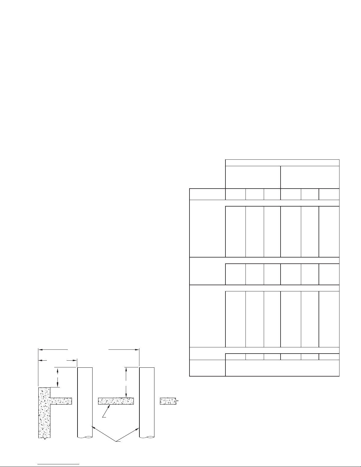
Model PIC/IPIC chimney is to terminate a minimum of 3’ (914)
above the highest point where it passes thru a roof of a building
and a minimum of 2’ (610) higher than any portion of a building
within a horizontal distance of 10’ (3.05m) (See FIG. 1).
FIG. 1 - TERMINATION HEIGHT REQUIREMENTS
MORE THAN 10’ (3048)
LESS THAN
10’ (3048)
2’ (610)
3’ MIN. (914)
STRUCTURE
CHIMNEY OR VENT
CLEARANCES – BOILERS AND ENGINES
CAUTION– DO NOT ENCLOSE IN A CHASE OR PASSAGEWAY
OF COMBUSTIBLE MATERIAL
For appliances operating with continuous exhaust temperatures
up to 1400º F, where the chimney is installed in an open room
or fully ventilated area on the same story as the appliance to
which it is connected, Model PIC/IPIC Chimney shall be installed
at a minimum of the clearance to combustibles as indicated in
TABLE 1.
Except for installation in one or two family dwellings, a factorybuilt chimney that extends through any zone above that on which
the connected appliance is located is to be provided with an
enclosure having a re resistance rating equal to or greater than
that of the oor or roof assemblies through which it passes.
Metal-Fab Model PIC/IPIC Chimney can penetrate a combustible
roof by utilizing the Roof Support Assembly (RSA) or Ventilated
Thimble Assembly (VTA). All other parts are for attachment to
non-combustible construction (i.e., oor guides, wall guides,
plate or wall support assemblies).
TABLE 1 - PIC/IPIC INSTALLATION CLEARANCES
Operating Temperature
1000°F Continuous
(538°C)
1400°F Intermittent
(760°C)
Insulation
Thickness
Exterior Wood Frame or Combustible Wall
Diameter: 6”
8 - 16”
24 - 26”
28 - 32”
36 - 40”
42 - 48”
Exterior Non-Combustible
Diameter: 6”
8 - 18”
20 - 42”
44 - 48”
Interior Wood or Other Combustibles
Diameter: 6”
8 - 16”
28 - 32”
36 - 40”
42 - 48”
Fully Enclosed Combustibles (UL103-HT)
Diameter: 6”-14” N/A N/A 2” (51) N/A N/A N/A
Fire Rated or
Non-Combustible
Chase
PIC IPIC-1
4” (102)
4” (102)
18”
5” (127)
20”
6” (152)
22”
6” (152)
6” (152)
6” (152)
34”
6” (152)
6” (152)
6” (152)
2” (51)
2” (51)
4” (102)
4” (102)
4” (102)
4” (102)
18”
5” (127)
20”
6” (152)
22”
7” (178)
24”
8” (204)
26”
9” (229)
10” (254)
34”
10” (254)
10” (254)
10” (254)
As necessary for installation and access, refer to NFPA 211.
4” (102)
5” (127)
5” (127)
6” (152)
4” (102)
4” (102)
5” (127)
5” (127)
6” (152)
1” (25)
2” (51)
3” (76)
3” (76)
3” (76)
3” (76)
1” (25)
2” (51)
3” (76)
1” (25)
2” (51)
3” (76)
3” (76)
3” (76)
3” (76)
3” (76)
IPIC-2
IPIC-4
1” (25)
1” (25)
1” (25)
1” (25)
1” (25)
1” (25)
1” (25)
1” (25)
1” (25)
1” (25)
1” (25)
1” (25)
1” (25)
1” (25)
1” (25)
1” (25)
1” (25)
1” (25)
1” (25)
1” (25)
1” (25)
1” (25)
1” (25)
3” (76)
3” (76)
Note: The above gures represent air space, in inches, from
outer surface to surroundings.
NOTES:
1. False ceilings are a potential hazard and require
restopping.Chimneyspassingthroughareasbetween
ceiling and roof must be installed in re-rated
enclosures in accordance with local building codes.
2. Decorative shrouds at the termination of a factory built
chimney shall not be permitted per NFPA 211.
3
1400°F Continuous
(760°C)
1800°F Intermittent
(982°C)
PIC IPIC-1
4” (102)
4” (102)
6” (152)
8” (204)
9” (229)
10” (254)
10” (254)
10” (254)
10” (254)
10” (254)
2” (51)
2” (51)
4” (102)
4” (102)
4” (102)
4” (102)
6” (152)
8” (204)
9” (229)
10” (254)
10” (254)
10” (254)
10” (254)
10” (254)
10” (254)
1” (25)
2” (51)
3” (76)
3” (76)
3” (76)
3” (76)
4” (102)
5” (127)
5” (127)
6” (152)
1” (25)
2” (51)
3” (76)
4” (102)
1” (25)
2” (51)
3” (76)
3” (76)
3” (76)
3” (76)
3” (76)
4” (102)
5” (127)
5” (127)
6” (152)
IPIC-2
IPIC-4
1” (25)
1” (25)
1” (25)
1” (25)
1” (25)
1” (25)
1” (25)
1” (25)
1” (25)
1” (25)
1” (25)
1” (25)
1” (25)
1” (25)
1” (25)
1” (25)
1” (25)
1” (25)
1” (25)
1” (25)
1” (25)
1” (25)
1” (25)
3” (76)
3” (76)
Page 4
USE AND INSTALLATION OF INDIVIDUAL PARTS:
These instructions comprise both general and specic
requirements for all parts in the product line. Before specifying a
design or beginning an installation, these instructions should be
carefully reviewed.
PIPE WEIGHT
The average weight of the chimney, per foot of length, can be
calculated using the following formula:
PIC: 0.80 x diameter = lbs per foot
IPIC-1: 0.95 x diameter = lbs per foot
IPIC-2: 1.05 x diameter = lbs per foot
IPIC-4: 1.45 x diameter = lbs per foot
Example: 8IPIC-2: 1.05 x 8 = 8.4 lbs per foot
Chimney design should make provisions for support adequate to
ensure that chimney parts are not overloaded.
PART NUMBERS
These instructions identify Model PIC/IPIC parts by name of part
number in the text and illustrations. Actual parts also carry a ue
diameter prex and a three digit “CTO” sufx which denes the
materials of construction, such as 24IPIC30-461 for a 24-inch
diameter double wall pipe section 30 inches long with Type 304
stainless steel inner wall, Type 316 stainless steel outerwall and a
1” insulation. (See Table 2 for further explanations of CTO codes).
TABLE 2
1st DIGIT
(INNER WALL)
4 = 304 S/S
6 = 316 S/S
A = ALUMINIZED STEEL
4 = 304 S/S
6 = 316 S/S
2nd DIGIT
(OUTER WALL)
3rd DIGIT
(INSULATION)
0 = 1” AIR SPACE
1 = 1” INSULATION
2 = 2” INSULATION
4 = 4” INSULATION
JOINT ASSEMBLY
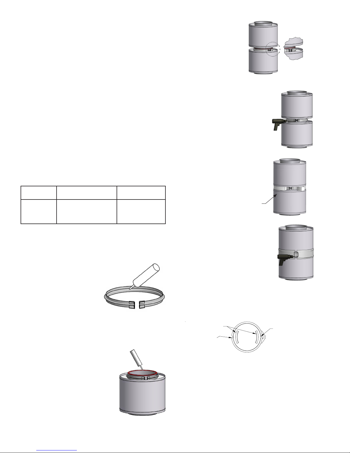
The Model PIC/IPIC joint sealing system is designed for quick and
easy installation. For most applications follow Steps 1 through 6.
(For High Pressure applications, see additional steps.)
STEP 1
Fill the channel of the ange band with
the proper sealant and install below ange
of rst pipe section.
NOTE: Sealant is to be supplied
by Metal-Fab. See TABLE 3
on Page 23 for number of
tubes per joint.
CAUTION: THE USE OF ANY OTHER SEALANT ON THE
FLANGE SURFACE WILL NEGATE ALL LISTINGS OF THE
PRODUCT AND IMPAIR THE SEALING EFFECTIVENESS.
STEP 2
Apply a continuous bead of proper sealant
to one of the anges to be joined.
NOTE: For gas temperatures up to 600ºF,
use P077 sealant.
For gas temperatures over 600ºF,
use P071 sealant.
For high pressure applications,
including ALL engine or
turbine exhaust applications, use P071 sealant.
STEP 3
Join the two anged ends of
the pipe sections.
STEP 4
Install the ange band around the anges.
NOTE: Do not locate V-Clamp
hardware at the bottom side
of horizontal duct joints.
When installing ange band, tap lightly with
hammer around periphery of band while
tightening draw screws. This helps to align
anges for the best seal. Do not overtighten
draw screws.
NOTE: Allow sealant to cure 24 hours
before operating appliances.
STEP 5
(IPIC Installations Only)
Pack the void between inner and outer
walls with insulation strips.
INSULATION STRIPS (PROVIDED)
STEP 6
Secure the outer casing with the closure
band.
When system is installed outdoors, the
upper side (upper half in the horizontal
position) of the closure band bead
should be sealed with P077 sealant to make
the casing watertight.
For all ENGINE EXHAUST and other HIGH PRESSURE
applications, perform Steps 1 through 3 above, then:
4. Install the seal clip(s) on the anges 6”, 8” and 10” only.
(See TABLE 4).
Note: 6” & 8” require two seal clips located as shown.
SEAL CLIPS
SEAL CLIP BETWEEN
FLANGE AND FLANGE
BAND NOTCH
SEAL CLIP BETWEEN
FLANGE AND
FLANGE BAND BOLT
CONNECTION
5. Install the ange band around the anges making sure
the joint is located so the seal clip overlaps both edges
of the joint.
6. Fill the space behind the ange band on both sides of
the ange with P071 pressure sealant (See FIG. 3).
7. Pack void between inner and outer walls with insulation
strips for IPIC installations.
8. Secure the outer casing with the closure band. Apply
sealant to closure band for exterior applications only.
See JOINT ASSEMBLY and FIG. 3 for llustrations of the
joining process and nished joint.
4
Page 5
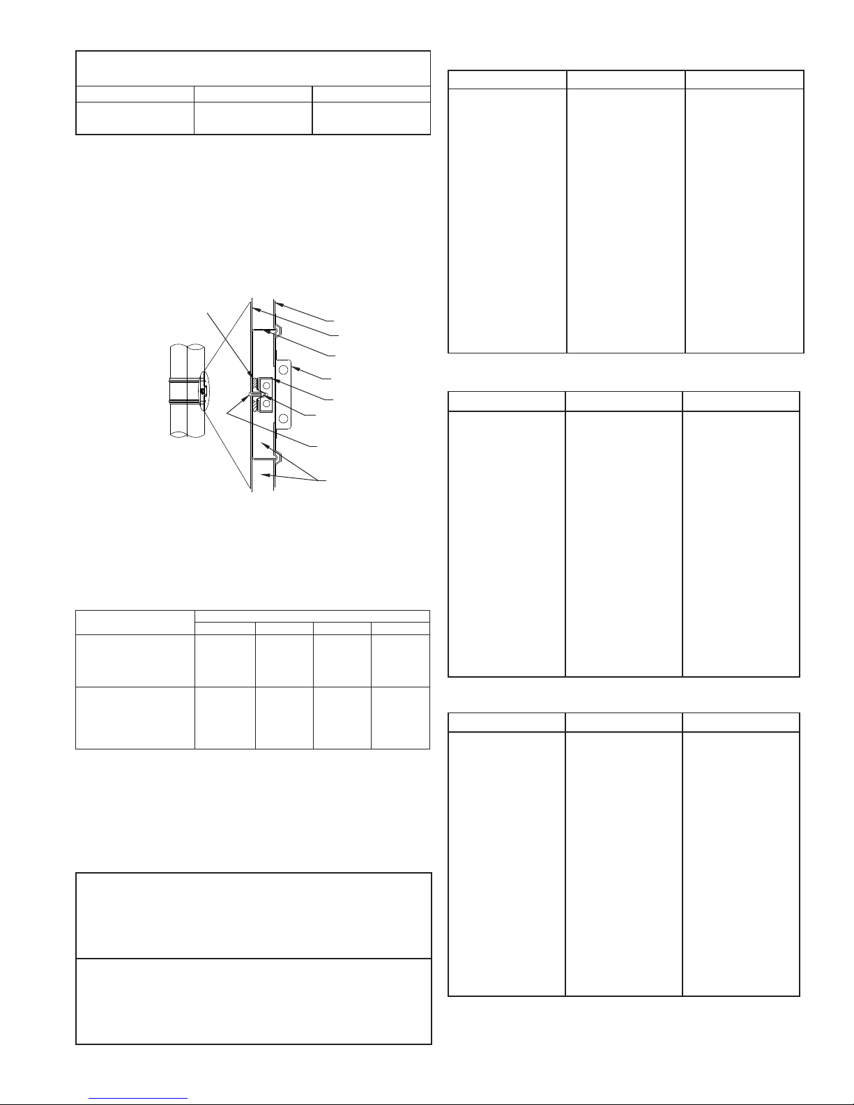
TABLE 4 - SEAL CLIPS REQUIRED PER JOINT
FOR PRESSURE SEALS
Pipe Diameter No. of Clips Part No.
6”-8” 2 SCK6-8*
10” 1 SCK10
*SCK6-8 contians 2 seal clips
Properly sealed joints are gas tight and resistant to water, oil
solvents and acids (except hydrouoric).
IMPORTANT: P071 Sealant must cure at operating
temperatures above 500°F at a minimum
3-hr curing time.
FIG. 3 – ASSEMBLED MODEL PIC JOINT
APPLY SEALANT BETWEEN
FLUE AND FLANGE BAND (SEE
STEP 6 ENGINE EXHAUST)
OUTER PIPE
INNER PIPE
SPACER CLIP
OUTER CLOSURE BAND
FLANGE BAND
APPLY SEALANT TO FLANGE
BAND (SEE STEP 1 JOINT
ASSY.)
APPLY SEALANT TO INNER
PIPE FLANGES (SEE STEP
2 JOINT ASSY.)
INSULATION (IPIC ONLY)
SUPPORT LIMITS - SUPPORT SPACING
TABLE 5 provides the maximum vertical distances between
supports for various support types. Using these supports, the
maximum installed chimney height is 200 feet (60.96m).
TABLE 5
Support Method Maximum Supported Height (meter)
Wall Support
Pier or Appliance Outlet
Plate Support Assembly
Roof Support Assembly
Stack Support Assembly
Fan Adapter Plate 6”-36” dia.
PIC IPIC-1 IPIC-2 IPIC-4
40’ (12.19m)
100’ (30.48m)
100’ (30.48m)
30’ (9.1m)
100’ (30.48m)
20’ (6m)
34’ (10.4m)
85’ (25.9m)
85’ (25.9m)
25’ (7.6m)
100’ (30.48m)
6”-28” dia.
20’ (6m)
30”-36” dia.
15’ (4.6m)
30’ (9.1m)
75’ (22.9m)
75’ (22.9m)
22’ (6.7m)
100’ (30.48m)
6”-26” dia.
20’ (6m)
28”-36” dia.
15’ (4.6m)
29’ (8.8m)
73’(22.3m)
73’(22.3m)
22’ (6.7m)
100’ (30.48m)
6”-18” dia.
20’ (6m)
20”-26” dia.
15’ (4.6m)
28”-36” dia.
10’ (3m)
GUIDE SPACING
TABLE 6 provides maximum distance between guides for
chimney installed inside building. (For exterior installations, See
TABLE 7 and FIG. 37.) These numbers represent ALL diameters
and vary depending on the amount of insulation.
TABLE 6
Maximum Unsupported Horizontal Spacing:
PIC
IPIC-1
IPIC-2
IPIC-4
Maximum Unsupported Vertical Spacing Below Roof Line:
PIC
IPIC-1
IPIC-2
IPIC-4
12’-6” (3.8m)
10’ (3.1m)
9’ (2.7m)
9’ (2.7m)
25’ (7.6m)
21’ (6.4m)
19’ (5.8m)
18’ (5.5m)
TABLE 7 - PIC & IPIC-1 GUYING REQUIREMENTS
Pipe Diameter “A” “B”
6”
8”
10”
12”
14”
16”
18”
20”
22”
24”
26”
28”
30”
32”
34”
36”
38”
40”
42”
44”
46”
48”
17’ 0” (5.18m)
17’ 6” (5.33m)
18’ 6” (5.64m)
20’ 0” (6.10m)
21’ 0” (6.40m)
22’ 0” (6.71m)
23’ 0” (7.01m)
24’ 0” (7.32m)
24’ 6” (7.47m)
25’ 0” (7.62m)
26’ 0” (7.92m)
27’ 0” (8.23m)
27’ 0” (8.23m)
28’ 6” (8.69m)
29’ 0” (8.84m)
30’ 0” (9.14m)
30’ 6” (9.30m)
31’ 0” (9.45m)
32’ 0” (9.75m)
32’ 6” (9.91m)
33’ 6” (10.21m)
34’ 6” (10.52m)
8’ 6” (2.59m)
8’ 9” (2.67m)
9’ 3” (2.82m)
10’ 0” (3.05m)
10’ 6” (3.20m)
11’ 0” (3.35m)
11’ 6” (3.51m)
12’ 0” (3.66m)
12’ 3” (3.73m)
12’ 6” (3.81m)
13’ 0” (3.96m)
13’ 6” (4.11m)
13’ 6” (4.11m)
14’ 3” (4.34m)
13’ 6” (4.11m)
15’ 0” (4.57m)
15’ 3” (4.64m)
15’ 6” (4.72m)
16’ 0” (4.88m)
16’ 3” (4.95m)
16’ 9” (5.10m)
17’ 3” (5.26m)
TABLE 7 - IPIC-2 GUYING REQUIREMENTS
Pipe Diameter “A” “B”
10”
12”
14”
16”
18”
20”
22”
24”
26”
28”
30”
32”
34”
36”
38”
40”
42”
44”
46”
48”
6”
8”
10’ 6” (3.20m)
12’ 0” (3.66m)
13’ 3” (4.04m)
14’ 6” (4.42m)
15’ 11” (4.85m)
17’ 0” (5.18m)
18’ 3” (5.56m)
19’ 6” (5.94m)
20’ 2” (6.15m)
20’ 9” (6.32m)
21’ 5” (6.53m)
22’ 1” (6.73m)
22’ 8” (6.91m)
23’ 4” (7.11m)
24’ 0” (7.32m)
24’ 7” (7.49m)
24’ 7” (7.49m)
24’ 7” (7.49m)
24’ 7” (7.49m)
24’ 7” (7.49m)
24’ 7” (7.49m)
24’ 7” (7.49m)
7’ 11” (2.41m)
8’ 5” (2.57m)
8’ 11” (2.72m)
9’ 5” (2.87m)
9’ 11” (3.02m)
10’ 6” (3.20m)
11’ 0” (3.35m)
11’ 6” (3.51m)
11’ 10” (3.61m)
12’ 3” (3.73m)
12’ 6” (3.81m)
13’ 1” (3.99m)
13’ 5” (4.09m)
13’ 10” (4.22m)
14’ 3” (4.34m)
14’ 7” (4.45m)
14’ 11” (4.55m)
15’ 3” (4.64m)
15’ 9” (4.80m)
16’ 3” (4.95m)
16’ 6” (5.03m)
17’ 0” (5.18m)
TABLE 7 - IPIC-4 GUYING REQUIREMENTS
Pipe Diameter “A” “B”
6”
8”
10”
12”
14”
16”
18”
20”
22”
24”
26”
28”
30”
32”
34”
36”
38”
40”
42”
44”
46”
48”
8’ 3” (2.51m)
9’ 7” (2.92m)
10’ 9” (3.28m)
11’ 11” (3.63m)
13’ 2” (4.01m)
14’ 2” (4.32m)
15’ 4” (4.67m)
16’ 4” (4.98m)
17’ 0” (5.18m)
17’ 7” (5.36m)
18’ 2” (5.54m)
18’ 9” (5.72m)
19’ 4” (5.89m)
19’ 11” (6.07m)
20’ 6” (6.25m)
21’ 0” (6.40m)
21’ 0” (6.40m)
21’ 0” (6.40m)
21’ 0” (6.40m)
21’ 0” (6.40m)
21’ 0” (6.40m)
21’ 0” (6.40m)
6’ 8” (2.03m)
7’ 3” (2.21m)
7’ 9” (2.36m)
8’ 4” (2.54m)
8’ 11” (2.71m)
9’ 6” (2.90m)
10’ 1” (3.07m)
10’ 8” (3.25m)
11’ 0” (3.35m)
11’ 6” (3.51m)
11’ 10” (3.61m)
12’ 4” (3.76m)
12’ 8” (3.86m)
13’ 2” (4.01m)
13’ 6” (4.11m)
13’ 11” (4.24m)
14’ 3” (4.34m)
14’ 8” (4.47m)
15’ 2” (4.62m)
15’ 8” (4.78m)
16’ 0” (4.88m)
16’ 5” (5.00m)
5
Page 6
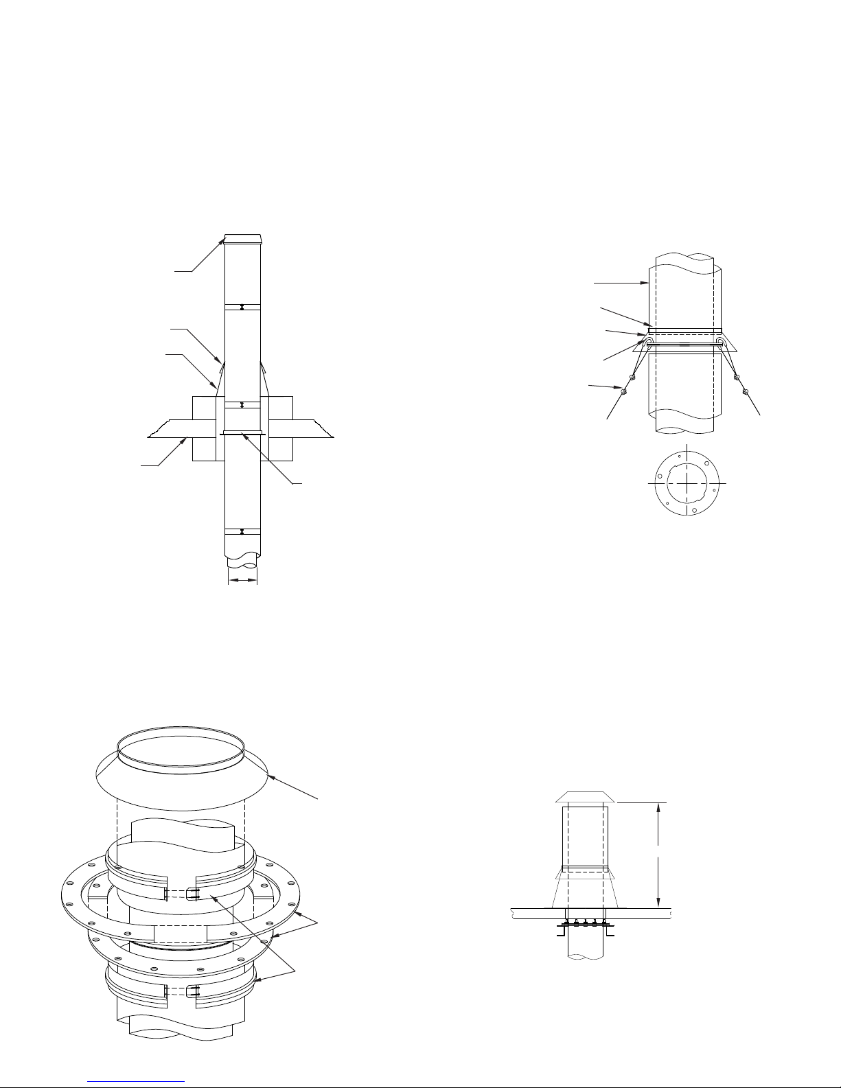
CHIMNEY ABOVE ROOF
When chimney is extended above rooine, special consideration
should be given to support and guying requirements. Use of a
standard or variable pitch ashing requires that the chimney be
stabilized to resist side loading. FIG. 4 and 8 depict methods
of protecting a ashing from side loads using a full angle ring
or plate support. Ventilated thimble and roof support assemblies
include lateral support rings, and additional guidance at the
rooine is not required.
FIG. 4 – FULL ANGLE RING FOR LATERAL SUPPORT
The guy ring consists of four (4) identical half rings with hardware
to secure them together, two (2) half closure bands and a storm
collar (FIG. 5). Select the joint where the guy ring is to be located
and assemble the inner wall joint (Steps 1 to 6 under JOINT
ASSEMBLY on Page 4). Sandwich the ange band between the
guy rings with the joints of the top and bottom rings 90º apart and
the cutouts aligned. Clamp the guy ring with the nuts and bolts
provided. Install the half closure bands above and below the guy
ring, then attach the cables or braces (See FIG. 6). Install the
storm collar above the upper half closure. The collar should be
caulked with sealant to prevent water entry.
FIG. 6 – GUY RING CABLE ATTACHMENT
CLOSURE RING
STORM COLLAR
FLASHING
ROOF
ANGLE RING MUST BE
USED WITH FLASHING
PIPE DIAMETER
GUY RING (GR)
Chimneys that extend above the roof, or are installed in severe
weather regions, may require a guy ring (GR) to enable the
chimney to resist wind loads. The guy ring is connected to
the building or other structure by means of cables or braces
TABLE 6 provides the spacing between guy rings and freestand
height for Model PIC/IPIC Chimney.
FIG. 5 - PIC/IPIC GUY RING, EXPLODED VIEW
CASING
APPLY SEALANT BETWEEN
COLLAR & CASING
STORM COLLAR
CABLE THIMBLE
CABLE CLAMPS
NOTE: Align large holes on
Guy Ring Halves during
assembly.
GUY RINGS DRILLED FOR
3 OR MORE CABLES
NOTE: Cable, cable clamps and cable thimble supplied by
others.
Cable or braces (supplied by the installer) should be slightly loose
to allow for thermal expansion for single guy ring installations
(FIG. 8) or be equipped with tensioning springs on multiple
guy ring installations (FIG. 9). To reduce the effect of thermal
expansion on the guy cables or braces, a xed-point support
(plate or wall support assembly) may be installed immediately
below the rooine as shown in FIG. 8.
NOTE: When chimney is installed outside building, adjacent
to wall, spacing between guides is equal to dimension “A”
in TABLE 6 (Refer to FIG. 34 on Page 15).
STORM COLLAR
GUY RING
HALF RINGS (4 PCS.)
HALF CLOSURE
BANDS (2 PCS.)
FIG. 7 – MAXIMUM FREE-STANDING HEIGHT ABOVE ROOF
“B”
NOTE: See TABLE 7 for “B” dimensions.
6
Page 7
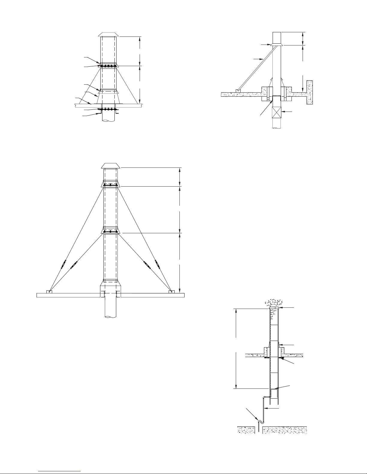
FIG. 8 – GUYING FOR SINGLE SECTION
STORM COLLAR
GUY RING
FIG. 10 – HEIGHT LIMITS FOR RIGID GUYING
“B”
“B”
(ON INSIDE OF COLLAR)
USE RIGID GUYS IF
CHIMNEY IS CLOSE TO
GUY RING
OUTSIDE WALL
MAXIMUM
SPACING
5 FT.
STORM COLLAR
FLASHING
ROOF
PLATE SUPPORT
SUPPORT STEEL
(BY INSTALLER)
“A”
NOTE: See TABLE 7 for “A” and “B” dimensions.
FIG. 9 – CHIMNEY GUYING REQUIREMENTS
A PLATE SUPPORT OR WALL
SUPPORT ASSEMBLY MUST BE
USED AT ROOF LEVEL WHEN
RIGID GUYING IS USED
EXPANSION JOINT
OR BELLOWS JOINT
NOTE: See TABLE 7 for “B” dimensions.
PIPE LENGTHS (9, 18, 30, 42)
Model PIC/IPIC pipe is available in 4 standard lengths: 9” (229),
“B”
18” (457), 30” (762) and 42” (1067). Pipe sections are joined,
using appropriate sealant, to make up desired length of run.
These sections may be modied by use of nipples or couplings
to accept auxiliary equipment such as temperature probes or
smoke monitors. Consult factory or your local representative to
obtain information regarding such modications.
“A”
DRAIN SECTION (DS)
A drain section is a special variation of an 18” (457) pipe length
with provision to drain rain or condensate from the chimney. The
pipe ue is equipped with an annular catch ring and a 1” (25)
NPT nipple extending through the casing for attachment of drain
piping. The drain piping should include a water leg of a height
at least equal to the maximum expected operating pressure at
“A”
the appliance outlet to avoid allowing ue gases to vent through
the drain. Drain section should be installed indoors to prevent
freezing (See FIG. 11).
NOTE: See TABLE 7 for “A” and “B” dimensions.
Cables should be spaced at or near 120º intervals (3 cables)
or 90º (4 cables). Rigid bracing requires two (2) braces spaced
between 60º and 150º apart. Maximum spacing between the
xed support and the guy ring is 5 feet when rigid bracing is used
(See FIG. 10).
FIG. 11 – DRAIN SECTION INSTALLATION
6 PIPE
DIAMETERS
OR MORE
TRAP HEIGHT EQUAL TO
MAX. APPLIANCE OUTLET
PRESSURE
1” PIPING
7
CLOSURE RING
FLASHING AND
STORM COLLAR
FULL RING GUIDE
DRAIN SECTION
Page 8
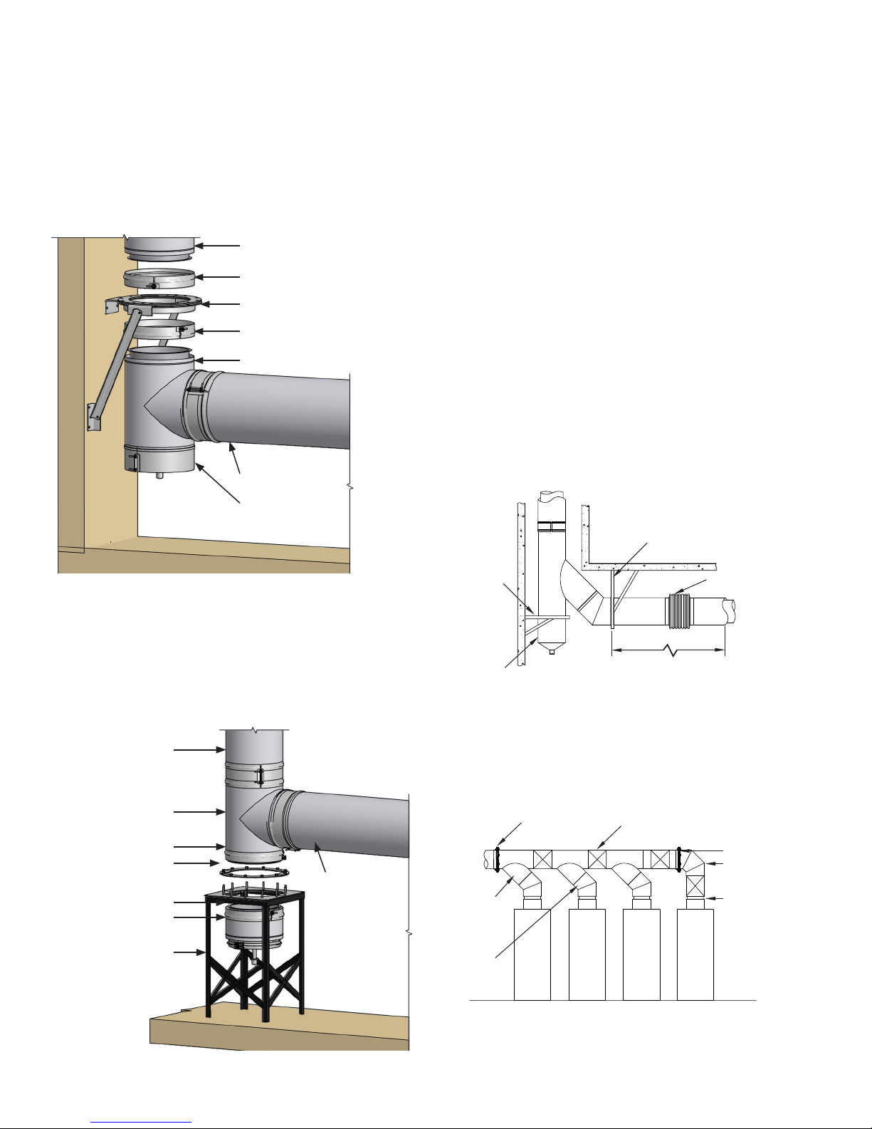
STANDARD 90º TEE (90MT)
The 90º Manifold Tee (90MT) may be used to connect horizontal
to vertical when a cleanout access or drain is desired. If more
than 1/4” (6) of thermal expansion is expected between the
tee and the next xed support point (the appliance outlet, for
example), the tee should be protected from bending moments
by use of an expansion joint or bellows joint. See the sections on
those ttings for additional information about compensation for
thermal expansion.
FIG. 12 – SUSPENDED TEE
PIPE RISER
HALF CLOSURE BAND
WALL SUPPORT ASSEMBLY
HALF CLOSURE BAND
TEE AT BASE OF RISER
DRAIN TEE CAP (TC), CLEANOUT CAP
The unused port of a tee must be closed to prevent leakage of
ue gases. A drain tee cap is used to close the tee and drain
condensation or rainwater when the tee is installed at the base of
a rise. When the tee is to be used for cleanout or access purpose
only, a cleanout cap (TCN) is recommended. Both the drain tee
cap and the cleanout cap are equipped with closures, which
serve the dual purpose of maintaining the double wall clearance
to combustible and giving the cap a nished appearance.
The drain tee cap’s drain nipple must be connected to a suitable
disposal point. Any rain entering the chimney will wash down
and remove any combustion residue from the chimney ue. The
resulting efuent may be corrosive. The tee cap must be sealed
at the connection to the tee using the appropriate sealant for the
application. This will assure that moisture will drain through the
drain nipple, as intended.
45º MANIFOLD TEE (45MT), DOUBLE LATERAL (DL)
For systems where minimizing ow resistance is desirable
or critical, a manifold tee having a 45º entrance to the trunk
is available. When used to make 90º turns, an additional 45º
elbow is required. It is particularly important to isolate the 45º
manifold tee from the effects of thermal expansion. This isolation
is typically accomplished by the use of a 2-axis support (See
FIG. 14). Otherwise, the installation details and precautions are
similar to those for the 90º manifold tee.
PIPE SECTION
DRAIN TEE CAP
When a tee is used at the base of a riser, the preferred location
for support is above the tee, thus suspending the tee (FIG. 12). If
it is not possible to suspend the tee, it may be supported from the
base of the tee (FIG. 13). When this type of support is necessary,
access to the drain cap may be hindered. A drain bucket should
be used under the tee to allow access to the tee cap.
FIG. 13 – BASE SUPPORTED TEE
PIPE RISER
TEE
HALF CLOSURE BAND
CLAMP RING
(SEE NOTE BELOW)
PIPE SECTION
FIG. 14 - TWO-AXIS SUPPORT METHOD
PLATE SUPPORT ATTACHED
TO BUILDING STRUCTURE
WALL SUPPORT
ASSEMBLY
DRAIN BUCKET
MORE THAN 1/4” THERMAL
EXPANSION EXPECTED
BELLOWS JOINT OR
EXPANSION JOINT
MULTIPLE APPLIANCE BREECHINGS (HEADERS)
When 90º or 45º manifold tees are used to manifold multiple
appliances together, it is important to make provisions for
expansion of the manifold. An expansion joint should be installed
between tees (See FIG. 15). The manifold must be supported
properly by means of plate supports or wall support assemblies
arranged to protect the tees from bending forces.
FIG. 15 – LATERAL TEE MANIFOLD
PLATE SUPPORT
ADJUSTABLE LENGTHS
OR BELLOWS JOINT
PLATE SUPPORT
90° ELBOW
HALF CLOSURE BAND
DRAIN BUCKET
STRUCTURAL STEEL
STAND (BY OTHERS)
45° MANIFOLD
TEE
45° FIXED
ELBOW
OUTLET
30º, 45º OR 90º FIXED ELBOWS (30L) - (45L) - (90L)
Elbows are not designed to resist bending loads and must be
protected by structural reinforcement. FIG. 16 depicts some
alternative methods for protection of elbows. Elbows may be
8
Page 9
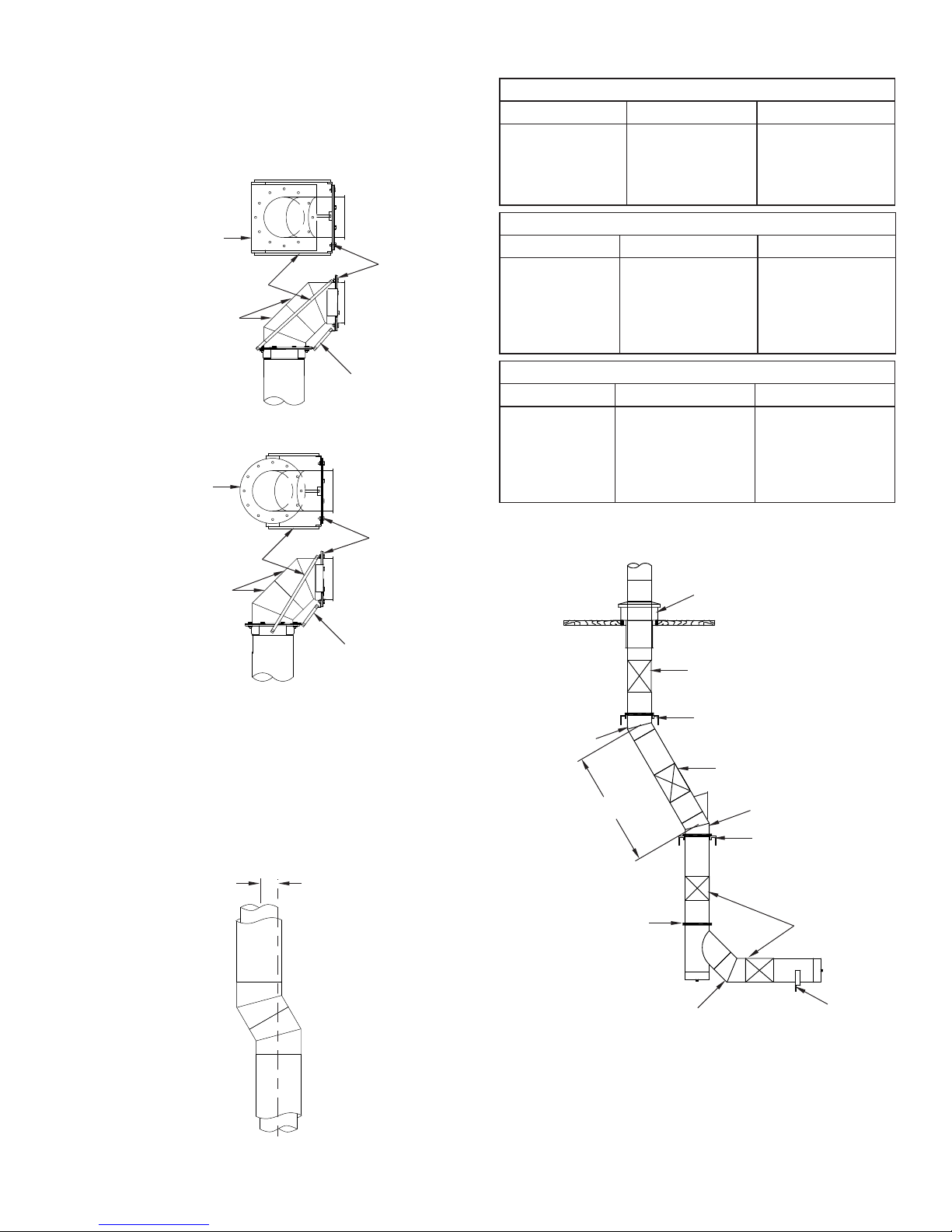
used singly or in combination to provide turns of 30, 45, 60,
75, or 90 degrees. For engine or turbine exhaust systems, it
is recommended that 90º turns be accomplished by using two
(2) 45º elbows or a combination of one 45º elbow and one 45º
manifold tee to minimize ow resistance.
FIG. 16 – METHODS OF STRUCTURAL REINFORCEMENT
FOR ELBOWS
TABLE 8 - MINIMUM OFFSETS
MINIMUM ELBOW OFFSETS PIC & IPIC-1
PIPE DIA. “A” - 30° ELBOW “A” - 45° ELBOW
6” thru 12”
14”
16” thru 24”
26” thru 36”
38” thru 48”
6” (152)
7 3/4” (197)
7 3/4” (197)
8 1/2” (216)
11” (279)
9 7/8” (251)
14 1/8” (359)
14 1/2” (368)
16 5/8” (422)
19 3/4” (503)
PLATE SUPPORT
PLATE SUPPORT
ANGLE
45° FIXED ELBOW
ANGLE BRACING
2-45° ELBOWS REINFORCED WITH PLATE SUPPORTS
WALL SUPPORT
PLATE SUPPORT
ANGLE
45° FIXED ELBOW
ANGLE BRACING
2-45° ELBOWS REINFORCED WITH WALL SUPPORTS
CHIMNEY OFFSETS
Offsets should be avoided except when there is no other way to
route the chimney. When an offset must be used, good design
indicates that the angle used should be the minimum possible (See
FIG. 18). If the appliance currently burns solid fuel or is capable
of being converted to burn solid fuel, the offset cannot exceed 30
degrees. No more than 2 offsets (4 elbows) may be used.
FIG. 17 — MINIMUM ELBOW OFFSETS
(REFER TO TABLE 8)
“A”
MINIMUM ELBOW OFFSETS IPIC-2
PIPE SIZE “A” - 30° ELBOW “A” - 45° ELBOW
6” thru 10”
12”
14” thru 22”
24” thru 34”
36” thru 46”
48”
6” (152)
7 3/4” (197)
7 3/4” (197)
8 1/2” (216)
11” (279)
12 3/4” (324)
9 7/8” (251)
14 1/8” (359)
14 1/2” (368)
16 5/8” (422)
19 3/4” (503)
23 3/4” (602)
MINIMUM ELBOW OFFSETS IPIC-4
PIPE SIZE “A” - 30° ELBOW “A” - 45° ELBOW
6”
8”
10” thru 18”
20” thru 30”
32” thru 42”
44” thru 48”
6” (152)
7 3/4” (197)
7 3/4” (197)
8 1/2” (216)
11” (279)
12 3/4” (324)
9 7/8” (251)
14 1/8” (359)
14 1/2” (368)
16 5/8” (422)
19 3/4” (503)
23 3/4” (602)
FIG. 18 – SUPPORT FOR CHIMNEY OFFSETS
VENTILATED THIMBLE ASSEMBLY
OR ROOF SUPPORT ASSEMBLY
EXPANSION JOINT
WALL SUPPORT ASSY.
30° FIXED ELBOW OR
45° FIXED ELBOW
MAX. 25 FT. (7620)
(OIL OR SOLID FUEL)
OR PLATE SUPPORT
EXPANSION JOINT
30° MAX. FOR OIL OR SOLID FUEL
30° FIXED ELBOW OR
45° FIXED ELBOW
WALL SUPPORT ASSY.
OR PLATE SUPPORT
TABLE 8 indicates minimum center to center offset for two
elbows connected directly to each other.
PLATE SUPPORT
45° FIXED ELBOW
EXPANSION JOINT
HALF ANGLE
RING
Bracing, above and below the elbows, is needed to avoid
subjecting them to bending moments. In order for bracing to
be effective, it must be rigidly attached to building members or
foundation. The design of the structure used to attach supports
must include the weight of the sloped section and whatever
additional pipe is carried by the support. Additionally, an
expansion joint or bellows joint is needed between the elbows to
relieve thermal expansion stresses.
9
Page 10
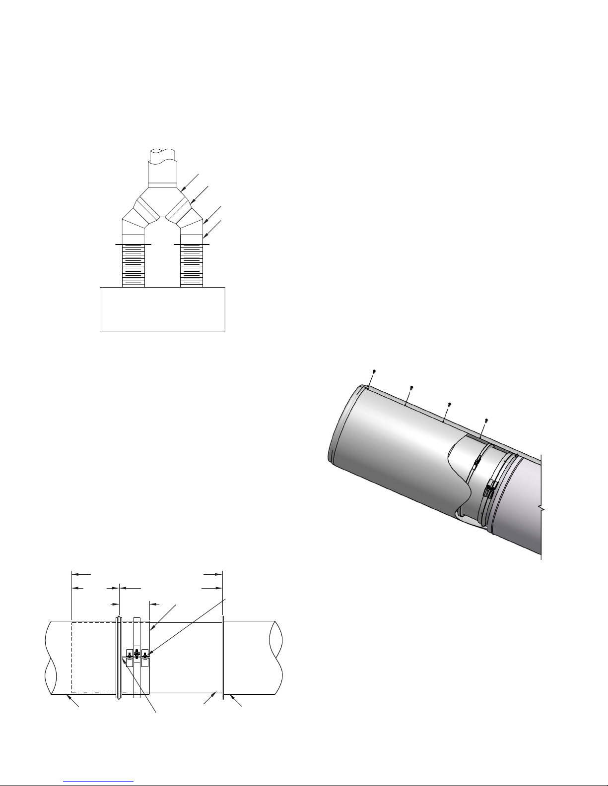
90º WYE (90Y)
The 90º wye is very useful when the vertical chimney is located
between two appliances and a low-loss junction is desired. It is
ideal for engine with dual-exhaust connections. The wye tting
may be suspended by a plate support or roof support assembly.
Expansion joints or bellows joints should be used to protect the
wye from thermal expansion stresses (See FIG. 19).
FIG. 19 – 90º WYE APPLICATION, DUAL EXHAUST
90° WYE
TAPERED INCREASER
45° FIXED ELBOW
FLANGE ADAPTER
ENGINE WITH
DUAL EXHAUSTS
Installation procedure is as follows:
1. Loosen draw screw at gasket band and slide collar toward
anged end of tube. Do not remove collar from tube.
2. Slide unanged end of tube into the upstream piece of pipe
and make up joint between pipe and collar following the
procedures outlined under heading JOINT ASSEMBLY on
Page 4.
3. Pull anged end of tube to the downstream piece of pipe and
make up joint as above (See FIG. 20).
4. For IPIC, cut insulation to desired length and wrap inner pipe
ensuring that it is covered completely before attaching half
jackets.
5. Wrap two half jackets around joint with bead at the
downstream end and punched edge overlapping plain edge
by approximate 3/4” (19). NOTE: For horizontal installations
the seams must be located at the top and bottom of the
pipe, coat unpunched edge of casing with P077 sealant to
waterproof the casing.
6. Install self-drilling screws (supplied with jacket) at punched
holed through both layers at overlap. Exercise care that half
jacket edges do not align with draw screws on ange bands
and that no screws are installed in portion of jacket which is
over casing of adjacent pieces of pipe (See FIG. 21). The
screws shipped with the expansion joint are of the correct
length to avoid penetrating the inner wall (ue) of the pipe.
Do not use any other screws to attach the casing.
EXPANSION JOINT (AL)
The expansion joint may be used to compensate for thermal
expansion and to make up odd lengths. It is essential that
sufcient installed length be allowed to compensate for abnormal,
as well as normal, operating conditions. The expansion joint
cannot be used to correct misalignment or to compensate for
lateral movement or vibration. The use of the expansion joint in
engine exhaust applications is not recommended.
An expansion joint is comprised of: (1) a collar that is 5¼” (133)
long with a ange and vee band at one end and a graphite
impregnated ring gasket at the other; (2) a 30” (762) long tube,
anged at one end, which ts into the 5¼” (133) collar; (3) an
outer jacket consisting of two half jacket assemblies; and (4)
loose insulation blanket to ll space between the tube and
casing.
FIG. 20 – EXPANSION JOINT FLUE ASSEMBLY
30” MAX. (762) OR TRIMMED AS REQ’D
8” MIN.
(203)
UNFLANGED END
INSTALLED LENGTH
3-3/4”
(95)
COLLAR
RETAINING
SCREWS
FIG. 21 - EXPANSION JOINT CASING ASSEMBLY
Note: Do not screw through casing of adjacent pipe.
ADJOINING PIPE
(DOWN SLOPE)
APPLY SEALANT
UNDER SEAM
(REF. JOINT ASSY. FOR
PROPER SEALANT)
PIPE
ADJOINING PIPE
(UP SLOPE)
10
Page 11
NOTES:
1. It is recommended that the pipe on both sides of the
expansion joint is supported or guided to assure that
the expansion joint will not bind during operation.
2. Installation of an expansion joint adjacent to ttings,
such as elbows, tees or wyes, is not recommended.
However, it is not always possible to avoid these
ttings. Ifanexpansionjointmustbejoinedtooneof
thesettings, theunanged endofthetubeshouldbe
awayfromthettingandttedintoapipelengthinthe
manner described in the installation procedure above.
3. Expansionjointmustbeinstalledwithaangetoange
length of not more than 22”. The minimum length for
installation must take into account the amount of
expansion that may occur during operation. Minimum
length is calculated as follows:
Expansion = Length (feet)/100 x Temperature Rise (ºF)/100
Minimum Length = Expansion + 6” (152mm)
It is recommended that the temperature used in the
above formula be at least 300ºF higher than the expected
normal operating temperature.
4. If inner tube is too long, it may be cut to length. Tube
must be a minimum of 8” (203) longer than ange-toangelength.Priortoinstallationofcutpipe,removeall
burrs to ensure that interference does not occur.
5. Check gasket to ensure that it ts snugly without
binding on inner pipe.
6. Outer jacket must move during expansion or
contraction. Ensure that no screws are located where
the jacket overlaps the casing of the adjacent pipe and
that it is loose enough to move as needed. Alignment
of the bead on the jacket with the bead on the adjacent
pipe will ensure that the jacket stays in the proper
location.
7. Note that the expansion joint will not support any
weight in the vertical position. It should not be used
unless both ends of run, where an expansion joint is
installed,areanchoredasxedpoints.
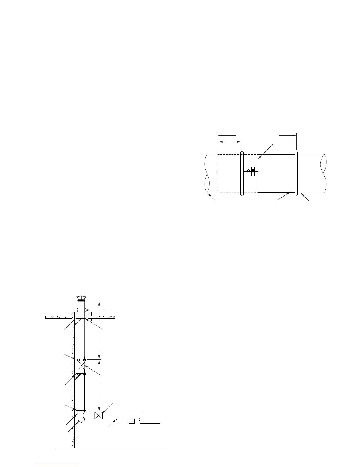
FIG. 22 indicates appropriate locations for expansion joints in
various orientations.
FIG. 22 – EXPANSION JOINT LOCATIONS
FLASHING
WALL GUIDE
WALL OR PLATE
SUPPORT
WALL GUIDE
FIXED POINT
PLATE SUPPORT
90° TEE
DRAIN TEE CAP
HALF OR FULL
ANGLE RING
CHIMNEY EXPANSION UP THROUGH
ROOF. GUIDANCE IS REQUIRED
THROUGH FLASHING OR THIMBLE
SEE TABLE 4 FOR
MAXIMUM DISTANCE
EXPANSION JOINT
ABSORBS UPWARD MOVEMENT
SEE TABLE 4 FOR
MAXIMUM DISTANCE
EXPANSION JOINT
CAREFULLY ALIGNED
VARIABLE LENGTH (VL)
The function of the variable length is to make up odd lengths of
pipe, which are not to be used for expansion compensation. The
use of the variable length in engine exhaust applications is not
recommended. The variable length is comprised of the following
components: (1) a 3¼” (83) collar with a ange at one end used
to clamp the ange at the desired length; (2) a 30” (762) long
tube anged at one end, which ts into the 3¼” (83) collar; (3)
an outer jacket consisting of two half jacket assemblies; and (4)
loose insulation blanket to ll space between the tube and casing.
A variable length can be installed at any ange to ange length
from 4”-26” (102-660). If the ue is too long to t into the adjacent
section of pipe without interfering with the ow path, it should be
trimmed to the desired ange to ange length plus 4” (102).
FIG. 23 VARIABLE LENGTH FLUE ASSEMBLY
30” (762) OR TRIM TO FIT
4” MIN.
(102)
UNFLANGED END
ADJOINING PIPE
(UP STREAM)
Installation procedure is as follows:
1. Loosen draw screw at collar and slide collar toward anged
end of tube. Do not remove collar from tube.
2. Slide unanged end of tube into the upstream piece of pipe.
Pull anged end of tube to the downstream piece of pipe
and make up joint as outlined under JOINT ASSEMBLY on
Page 4.
3. Apply a thin coat of sealant, about 1” (25) wide at the plain
end of the pipe where tube slides into mating pipe section.
Press sealant into any gap between the tube and the
mating pipe section. Apply sealant to ange of mating pipe
(See FIG. 23).
4. Slide collar into position against ange of mating pipe. Fill
ange band with sealant and install ange band.
5. Tighten bolts on clamp collar to complete installation. (For
more positive seal, apply sealant to clamp collar slot and
ared end of collar prior to tightening bolts).
6. For IPIC, cut insulation to desired length and wrap inner pipe
ensuring that it is covered completely before attaching half
jackets.
7. Wrap two half jackets around joint with bead at the
downstream end and punched edge that overlapping the
plain edge by approximately 3/4”. Note: For horizontal
installations, the seams must be located at the top and
bottom of the pipe. Coat unpunched edge of casing with
P077 sealant to waterproof the casing. Install self-drilling
screws (supplied with jacket) at punched holed through both
layers at overlap. Exercise care that half jacket edges do not
align with draw screws on ange bands, and that no screws
are installed in portion of jacket which is over casing of
adjacent pieces of pipe (See FIG. 24). The screws shipped
with the expansion joint are of the correct length to avoid
penetrating the inner wall (ue) of the pipe.
Do not use any other screws to attach the casing.
TUBE
COLLAR
ADJOINING PIPE
(DOWN STREAM)
11
Page 12
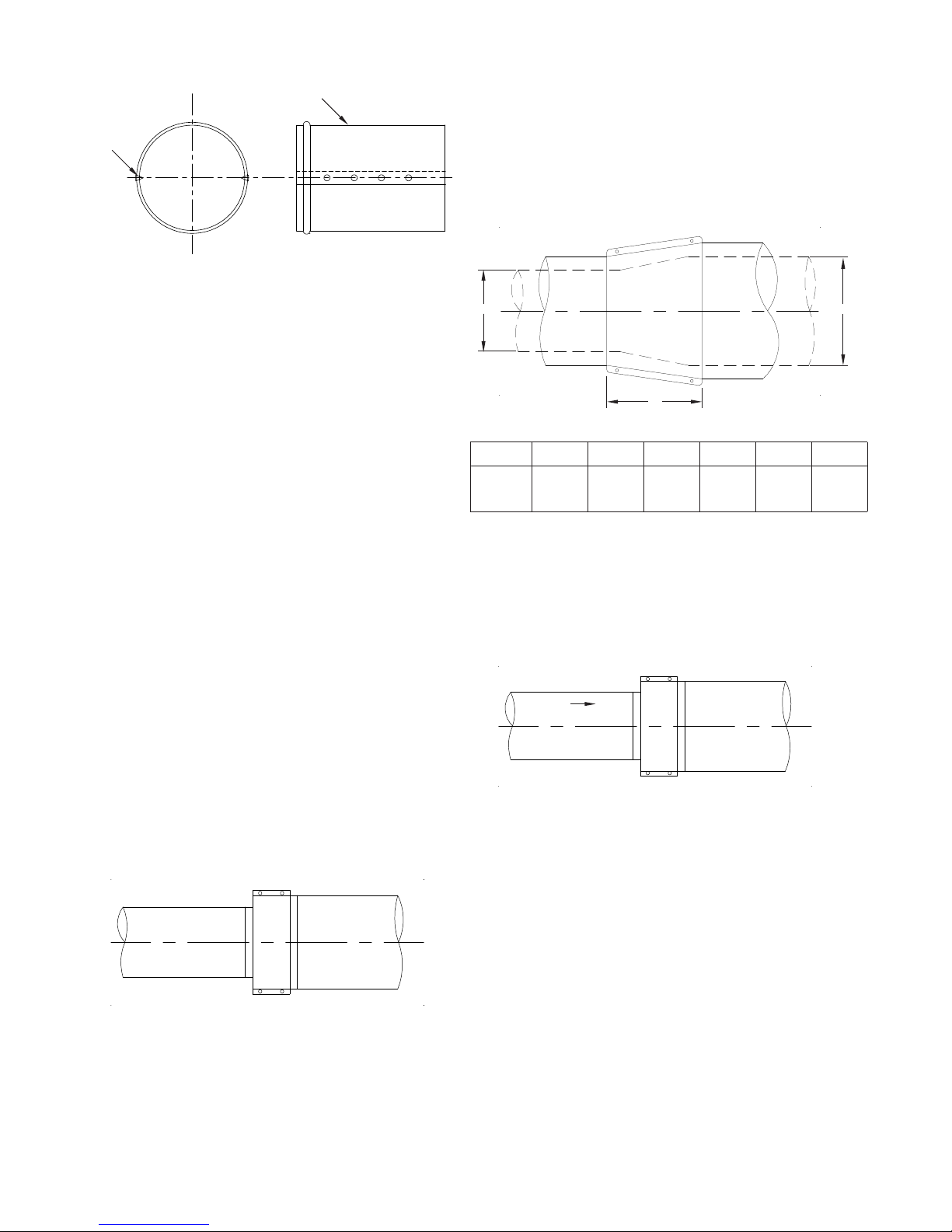
FIG. 24 – VARIABLE LENGTH CASING ASSEMBLY
HALF JACKET
SCREWS
(INCLUDED)
NOTES:
1. It is recommended that the pipe adjacent to the variable
length is supported or guided to prevent sagging.
2. If a variable length must be installed adjacent to a tee,
elbow,wyeorotherttingwheretubecaninterferewith
ow,theunangedendofthetubeshouldbeawayfrom
the tting and tted into a pipe length in the manner
described in the installation procedure under FIG. 23.
3. Avariablelengthmaybeinstalledwithaangetoange
length between 4” and 26” (102 and 660) inclusive.
4. If inner tube is too long, it may be cut to length. Tube
must beaminimumof4”(102)longerthanange to
angelength.Priortoinstallationofcutpipe,removeall
burrs to ensure that interference does not occur.
5. Note that the variable length will not support any weight
in the vertical position.
STEP INCREASER (SI) AND TAPERED INCREASER (TI)
Frequently, a diameter change is required in a chimney
installation. To accomplish such a size change, a step increaser
or tapered increaser may be used. These parts are usually used
to provide an increase of size, as the name implies. However,
they may be used to reduce the size of a run. Extreme caution
should be exercised when reducing the size of a chimney. The
resultant pressure drop may cause the chimney to mis-function
and cause spillage of ue gases into the mechanical room.
The step increaser should be used when the length of run
available for the size change is restricted. The installed length of
a step increaser is 2” (51) (See FIG. 25). The step increaser is a
non-structural part and must not be subjected to loading in either
the axial or lateral directions.
FIG. 25 - STEP INCREASER (SI)
INSTALLS AT 2” (51)
When sufcient length is available, use of a tapered increaser
is recommended, since it causes a considerably less pressure
drop than an equivalent step increaser. The tapered increaser
uses 5 inches of length per incremental diameter change. The
maximum length for a tapered increaser is 30” (762) or 6 pipe
sizes. A tapered increaser is considered to have the same load
strength as straight pipe (See FIG. 26).
FIG. 26 - TAPERED INCREASER (TI)
“A”
STEPS
“C” =
“C”
1 2 3 4 5 6
5”
(127)
10”
(254)
15”
(381)
20”
(508)
25”
(635)
“B”
30”
(762)
TRANSITION BAND (TB)
The transition band provides the necessary increase or decrease
in casing diameter when change in insulation thickness occurs
(FIG. 27).
FIG. 27 - TRANSITION BAND (TB)
AIR FLOW
Note: Wrap pipe joint with insulation before attaching outer
casing.Caremust be takentocompletely llallgapswith
insulation.
Note: For IPIC, wrap increaser with insulation before
attachingoutercasing.Caremustbetakentocompletelyll
all gaps with insulation.
12
Page 13
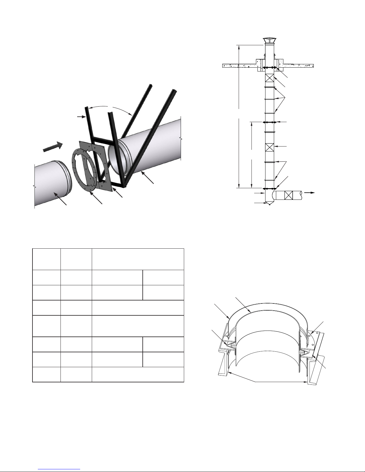
PLATE SUPPORT (PS)
NOTE: See TABLE 5 for maximum supported height.
The plate support assembly is designed to provide maximal
support to vertical sections and to provide xed-point support for
horizontal sections. The plate support must be attached to the
building structure or support with rigid structural members.
FIG. 29 – RESUPPORT REQUIREMENTS
FIG. 28 – PLATE SUPPORT BRACING REQUIREMENTS
“X”
BRACING
(BY OTHERS)
EXHAUST FLOW
PIPE SECTION
PLATE SUPPORT
PIPE SECTION
CLAMP RING
“X” is a minimum of 30° when bracing is used. A welded frame
must be adequately attached to structural member for framework
rigidity if bracing isn’t used.
Pipe
Diameter
PS Plate
Thickness
Bracing for (PS) Plate Support
Height of Stack
50’ (15.24m) 100’ (30.48m)
6” - 20” 3/16” (5) 1 1/4”x1 1/4”x1/8”
(32x32x3)
22” - 36” 1/4” (6) 2”x2”x1/8”
(51x51x3)
2”x2”x1/4”
(51x51x6)
3”x3”x1/4”
(76x76x6)
38” - 48” 1/4” (6) 3” (76) channel: 3”x1 1/2”x1/4”
(76x38x6)
Pipe
Diameter
PS Plate
Thickness
Framework for (PS) Plate Support
Height of Stack
50’ (15.24m) 100’ (30.48m)
6” - 20” 3/16” (5) 1 3/4”x1 3/4”x1/8”
(44x44x3)
22” - 36” 1/4” (6) 2”x2”x1/4”
(51x51x6)
3”x2”x3/16”
(76x51x5)
4”x3”x1/4”
(102x76x6)
38” - 48” 1/4” (6) 3” channel: 3”x1 1/2”x1/4”
(76x38x6)
When the supported section is subject to thermal expansion
or is in a vertical position, so that the plate support is weight
bearing, the support structure must be braced with diagonal
members or gussets to prevent deection of the supported joint
(See FIG. 28). Plate supports are usually located adjacent
to ttings, such as tees or elbows, to protect the tting from
expansion stresses. Chimneys heights in excess of a single
plate support capability can be resupported with additional plate
support(s). An expansion joint must be used between support
points (See FIG. 29).
PLATE SUPPORT
EXPANSION JOINT
FULL ANGLE RINGS
200 FT. (60.96M)
MAXIMUM
PLATE SUPPORT
100 FT.
(30.5M)
90° TEE
DRAIN
TEE CAP
EXPANSION JOINT
FULL ANGLE RINGS
PLATE SUPPORT
TO APPLIANCE
A plate support assembly is to be attached only to
non-combustible construction such as block, concrete or steel
with clearance that is adequate for installation and access.
DO NOT ATTACH THE PLATE SUPPORT TO COMBUSTIBLE
CONSTRUCTION.
For maximum support, the entire perimeter of the plate support
assembly must be attached to structural framing (See FIG. 30).
Structural members are supplied by the installer.
FIG. 30 – SECTIONAL DETAIL FOR PLATE SUPPORT
FLUE
CASING
CLAMP
FLANGE
BAND
STRUCTURAL BRACING
(BY OTHERS)
RING
PLATE
NOTE: Clamp ring sections and plate sections install at
90° angles.
13
Page 14
FULL ANGLE RING (FAR) AND HALF ANGLE
RING (HAR)
The full angle ring is used as a guide to prevent the chimney from
exing due to lateral loading. The angle ring is split for ease of
installation. It is 1/8” larger in inside diameter than the outside
diameter of the pipe to allow movement of the pipe inside the
ring (See FIG. 31).
The clamp rings are installed with the splits 90º apart so that they
support each other. The notches in the clamp rings are aligned
with the draw screws of the ange band. The clamp rings and full
angle ring are then bolted together with the hardware provided to
form a rigid assembly (See FIG. 33).
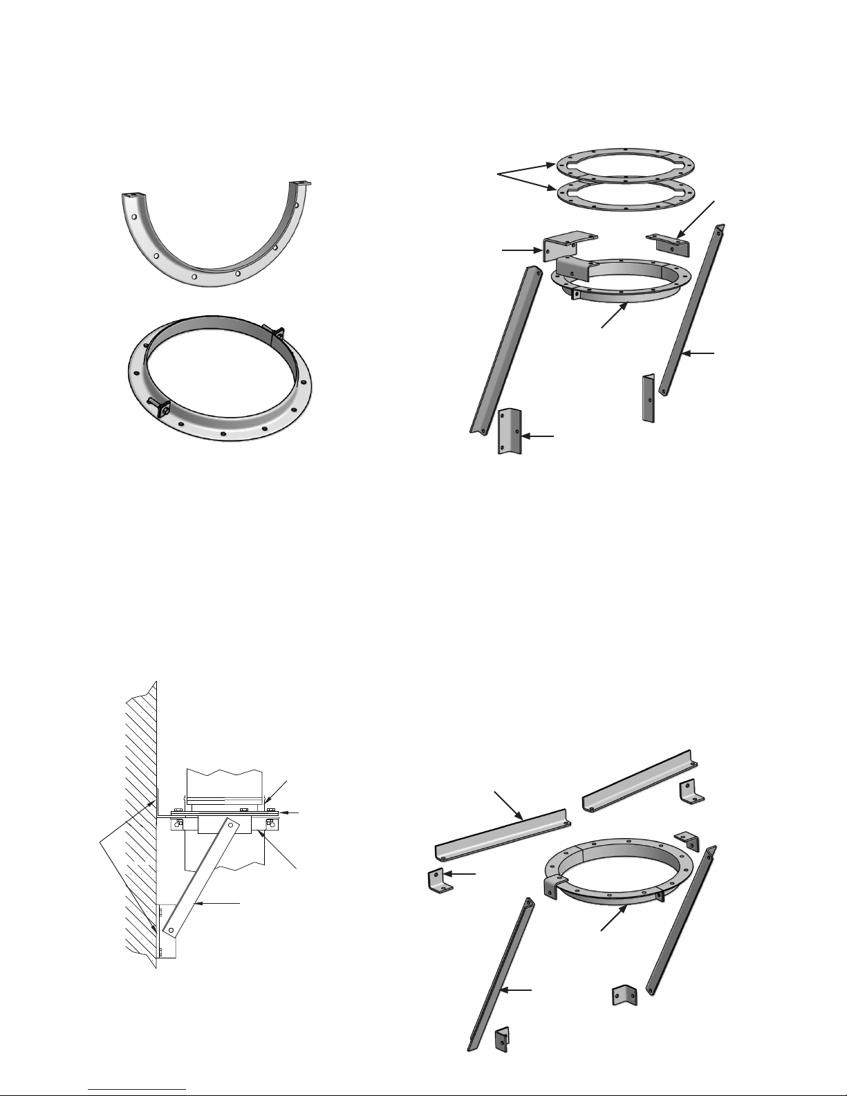
FIG. 33 WALL SUPPORT ASSEMBLY EXPLODED VIEW
FIG. 31 – FULL ANGLE RING & HALF ANGLE RING
HALF ANGLE RING
FULL ANGLE RING
The half angle ring is used as a saddle in horizontal or sloped
runs. It may be suspended either on rigid framework or soft
frames, such as threaded rod. The half angle ring will not replace
a plate support or other xed support in horizontal runs. It should
not be used as the sole support for the chimney.
WALL SUPPORT ASSEMBLY (WSA)
A wall support assembly consists of a full angle ring, two clamp
rings, wall brackets and struts. The clamp rings sandwich a
ange band at a pipe joint and are supported by the full angle
ring (See FIG. 32).
FIG. 32 – WALL SUPPORT ASSEMBLY ASSEMBLED VIEW
CLAMP RING
BRACE
BRACKET
WALL BRACKET
FULL ANGLE
RING
STRUT
STRUT WALL
BRACKET
When attached to a non-combustible wall, with the brackets and
struts, the wall support makes up a xed-point in the chimney. An
expansion joint is required between the wall support assembly
and any adjacent xed point.
Multiple wall support assemblies may be used, in conjunction
with expansion joints or bellows joints, to support chimney
heights in excess of the allowable height for a single wall support
assembly.
DO NOT ATTACH THE WALL SUPPORT ASSEMBLY TO
COMBUSTIBLE CONSTRUCTION.
WALL GUIDE (WG)
The wall guide is designed to compliment the wall support
assembly. It is used as a lateral guide to prevent the chimney
from exing due to lateral loading.
The wall guide consists of a full angle ring with wall brackets and
struts (See FIG. 34 & 35).
FIG. 34 – WALL GUIDE ASSEMBLY EXPLODED VIEW
BRACKETS
STRUT
Note: For IPIC, wrap pipe joint with insulation before attaching half
closure bands.
HALF CLOSURE
BAND
CLAMP FLANGE
SUPPORT RING
14
HORIZONTAL
STRUT
WALL
BRACKET
FULL ANGLE
VERTICAL
STRUT
RING
Page 15
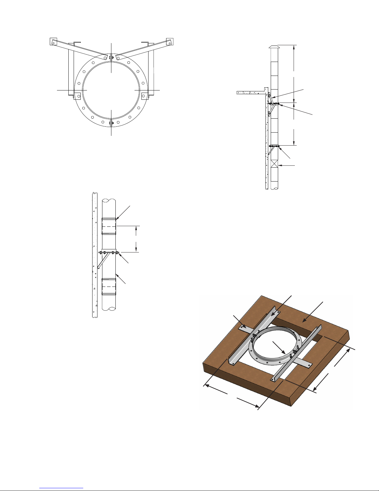
FIG. 35 – WALL GUIDE ASSEMBLED VIEW
The proper location for a wall guide is immediately below the
outer closure band near a pipe joint. The outer band must be
able to move away from the wall guide when thermal expansion
occurs (See FIG. 36).
FIG. 36 – WALL GUIDE LOCATIONS
FIG. 37 – SPECIAL CONSIDERATIONS FOR CHIMNEY ON
OUTSIDE WALL
FREE STANDING
38” THRU 48” PIC ONLY
WALL SUPPORT
6 TO 10 FEET
(1829 -3048)
WALL GUIDE
DO NOT INSTALL AN
EXPANSION JOINT IN
THIS AREA DUE TO
BENDING FORCES
LOCATE EXPANSION JOINT
OR BELLOWS JOINT BELOW
WALL GUIDE
PIPE FLANGES
6”-12” (152-305)
WALL GUIDE OR
FULL ANGLE RING
(STRUCTURE BY
OTHERS)
PIPE
DO NOT ATTACH THE WALL GUIDE TO
COMBUSTIBLE CONSTRUCTION.
SPECIAL CONSIDERATIONS
When a wall support assembly is used to support a chimney on
an exterior wall, wind loading must also be considered. Below the
highest wall support assembly, the chimney must be resupported
at intervals not greater than 40’ (12.19m) (See TABLE 5). The
chimney must be equipped with wall guides between each wall
support assembly. Guide spacing is in accordance with maximum
vertical spacing in TABLE 6 on Page 5. Additionally, a wall guide
must be located between 6’ and 10’ (1.83m and 3.05m) below the
highest wall support to stabilize the freestanding portion of the
chimney above the wall support assembly (See FIG. 37).
FLOOR GUIDE (FG)
The oor guide is similar in function to a wall guide or full angle
ring, but is modied specially for use at oor penetrations. The
angle brackets and straps hold the guide centered in the oor
penetration (See FIG. 38). Maximum oor opening “X” is Duct
I.D. + 10” (254).
FIG. 38 – FLOOR GUIDE
ANGLE
BRACKET
STRAPS
ANGLE
RING
“X”
DO NOT ATTACH THE FLOOR GUIDE TO
COMBUSTIBLE CONSTRUCTION.
FLOOR
“X”
15
Page 16
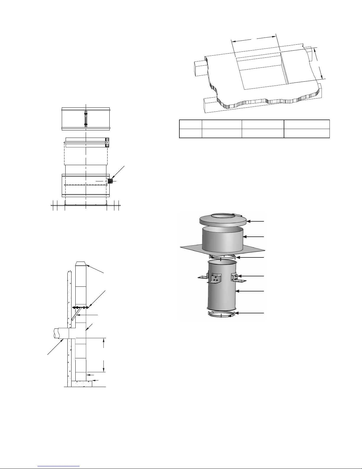
STACK SUPPORT ASSEMBLY (SSA)
The stack support assembly is intended for use as a base mount
for mounting the stack on a concrete oor or a structural steel
stand. It is equipped with a predrilled steel baseplate for the
insertion of anchor bolts or studs. A 9-inch section of pipe is
attached to the baseplate and contains a false bottom 4½” (114)
above the oor. A 1” (25) NPT nipple extends through the side of
the pipe section just above the false bottom to allow drainage of
rain or condensate (See FIG. 39). It is recommended that a 90º
manifold tee with a cleanout cap be installed above the stack
support to provide access to the stack.
FIG. 39 – STACK SUPPORT ASSEMBLY
1” N.P.T. NIPPLE
FIG. 41 – ROOF FRAMING FOR VENTILATED THIMBLE
ASSEMBLY OR ROOF SUPPORT ASSEMBLY
“X”
“X”
Model PIC & IPIC-1 IPIC-2 IPIC-4
“X” I.D. + 8” (203) I.D. + 10” (254) I.D. + 14” (356)
The roof support assembly is a special variation of the ventilated
thimble which also provides vertical support to the chimney. It is
especially useful when the chimney rise below the roof is long
enough to cause movement from thermal expansion to exceed
approximately 2” (51).
The ventilated thimble consists of the thimble with 4 support
brackets; 2 lateral support rings, split for ease of installation; a
ashing; a storm collar.
When using a stack support assembly as the stack base, it is
important to use exact pipe lengths to raise the stack height to
the breeching connection point (See FIG. 40). Use of variable
lengths or expansion joints in the stack under the breeching
connection defeats the purpose of the stack support assembly.
These components will not support weight.
FIG. 40 – STACK SUPPORT ASSEMBLY INSTALLATION
EXIT CONE
FULL ANGLE RING
BRACING (BY OTHERS)
90° TEE
NOTE: DO NOT USE VARIABLE LENGTH OR
BREECHING
EXPANSION JOINT BETWEEN BREECHING &
STACK SUPPORT ASSY.
STACK SUPPORT ASSEMBLY
CONCRETE PAD OR
STRUCTURAL BASE
VENTILATED THIMBLE ASSEMBLY (VTA) AND ROOF
SUPPORT ASSEMBLY (RSA)
The ventilated thimble assembly is designed to allow Model
PIC/IPIC chimney to penetrate a combustible roof at a nominal
3” clearance to combustibles. FIG. 41 illustrates the required
minimum framing dimensions. The ventilated thimble is intended
for installation on a at roof. It may be used on a pitched roof if a
curb is installed at the penetration to provide a level surface for
mounting the thimble.
FIG. 42 - VENTILATED THIMBLE ASSY. INSTALLATION
STORM COLLAR
FLASHING
LATERAL SUPPORT RING
SUPPORT BRACKET
THIMBLE
LATERAL SUPPORT RING
Installation of the ventilated thimble is as follows (See FIG. 42):
1. Cut the roof opening and reinforce the edges of the hole
as appropriate for the expected load bearing requirements.
Attach the thimble brackets to the thimble using the
hardware provided.
2. Set the thimble through the roof, making sure it is centered
in the roof penetration hole, and secure it to the roof deck
with bolts or lag screws supplied. The brackets may be
welded to a metal roof, if desired.
3. Install the chimney passing through the thimble and
extending above the roof.
4. Install the 2 split lateral support rings on the chimney casing,
one above the thimble and one below the thimble. Leave
the bolts loose enough to allow the ring to slide along the
casing. The spacer tabs are to be toward the thimble.
5. Push the lateral rings along the chimney casing until they
are completely enclosed in the thimble.
6. Install the ashing centered on the thimble. Secure it to the
roof and seal it to the roof membrane as appropriate.
16
Page 17
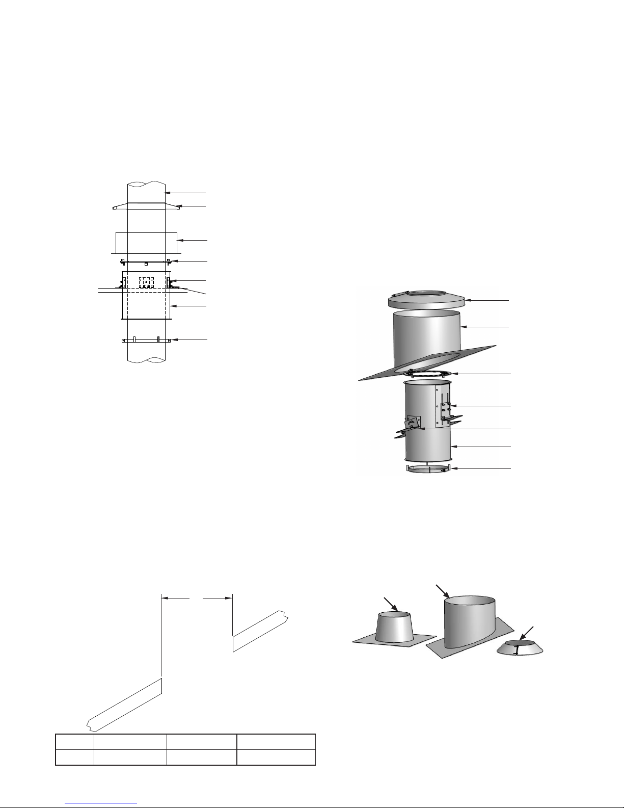
7. Install the storm collar around the chimney casing allowing
the ventilation spacers on the underside of the collar to rest
on the upper edge of the ashing. Tighten the draw screw
and seal between the collar and the chimney casing with
chimney sealant.
The roof support assembly consists of the same parts as the
ventilated thimble except that one of the lateral rings is replaced
with a vertical support ring. Installation is identical to the ventilated
thimble except step 4 (See FIG. 43).
FIG. 43 - ROOF SUPPORT ASSY. INSTALLATION
PIPE O.D.
STORM COLLAR
FLASHING
1. The roof opening is sized as a at projection (See FIG. 44)
to provide the correct clearance.
2. The thimble is centered in the roof hole with the two pivoting
brackets oriented parallel to the roof ridge and the hinged
brackets running up and down the roof. The brackets are
secured to the roof with bolts, lag screws or welding as
appropriate. Leave the bolts of the sliding mount loose until
the brackets are attached to the roof. Then tighten all bolts
and nuts.
3. Install the ashing centered on the thimble. Secure it to the
roof and seal it to the roof membrane as appropriate.
Note: The ashing pitch is xed, specify required pitch rate
with order.
FIG. 45 illustrates details of the pitched roof penetration
component installation.
VERTICAL SUPPORT RING
BRACKET
LAG SCREW OR BOLT
THIMBLE
LATERAL SUPPORT RING
Install lateral support ring below thimble as per step 4 above.
Then install the vertical support ring. Vertical ring consists of 2
half-clamp rings designed to lock together when assembled.
The pipe section joint will rest on top of the assembled vertical
support ring. The vertical support ring will rest on top of Thimble
Flange and carries the weight of the chimney. Because it is not
fastened to the thimble, the chimney can expand upward in the
thimble if needed.
FIXED PITCH VENTILATED THIMBLE ASSEMBLY
(FPVTA) AND FIXED PITCH ROOF SUPPORT
ASSEMBLY (FPRSA)
These components are special variations of the ventilated thimble
assembly. They provide the same clearance to combustibles and
types of support, but are designed to be installed in pitched
roofs. Installation is similar to the at roof versions except for
the following.
FIG. 44 – ROOF FRAMING FOR VENTILATED THIMBLE
ASSEMBLY OR ROOF SUPPORT ASSEMBLY
“X”
FIG. 45 – FIXED PITCH ROOF PENETRATION
INSTALLATION
STORM COLLAR
PITCHED FLASHING
VERTICAL OR LATERAL
SUPPORT RING
HINGED BRACKET
PIVOTING BRACKET
THIMBLE
LATERAL SUPPORT RING
FLASHING (F) FIXED PITCH FLASHING (FPF) AND
STORM COLLAR (SC)
Flashings, both standard (Tall Cone) and pitched, are intended
for installation on non-combustible roofs only. The ashing is
non-ventilated and does not provide for any reduced clearance
to combustibles.
FIXED PITCH
TALL CONE
FLASHING (F)
FLASHING (FPF)
Model PIC & IPIC-1 IPIC-2 IPIC-4
“X” I.D. + 8” (203) I.D. + 10” (254) I.D. + 14” (356)
STORM
COLLAR (SC)
To install the ashing, place it around the chimney. Secure and
seal it to the roof (FIG. 46).
17
Page 18
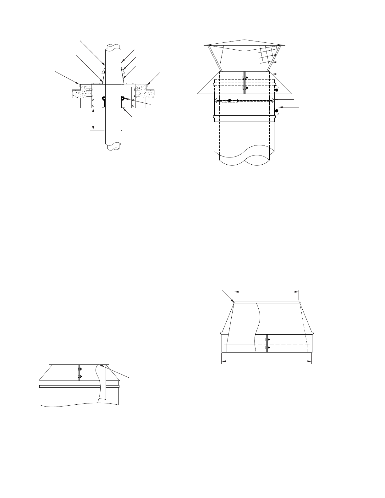
FIG. 46 – INSTALLATION OF FLASHING AND STORM
COLLAR
SEALANT
DO NOT RESTRICT
VERTICAL MOVEMENT
OF FLANGE BAND
CURB
FLANGE BAND
STORM COLLAR
TALL CONE FLASHING
16 GA. PAN
FIG. 48 - STACK CAP
OPTIONAL BIRD SCREEN
CAP
CLOSURE RING
(INCLUDED)
PLATE
MAINTAIN
ADEQUATE
EXPANSION
STRUCTURAL FRAME
With the ashing in place, the storm collar is placed around the
chimney and sealed to the casing with silicone sealer. The storm
collar should not quite rest on the ashing when the chimney is
cold (1/4” gap between the collar and the top of the ashing).
When a chimney is installed with a ashing and collar rather than
a ventilated thimble, the chimney must be stabilized by installing
either a full angle ring or a plate support just below the roof. If the
chimney height above the plate support or full angle ring exceeds
the “B” dimension in TABLE 7 on PAGE 5, it must be guyed to
avoid wind damage.
CHIMNEY TERMINATIONS
STACK CLOSURE RING (CR)
The stack closure ring (FIG. 47) is the simplest method of
terminating a chimney. It provides protection of the annular
space between the inner and outer walls and leaves the top of
the chimney open to the elements. A drain section (or tee with
drain tee cap) should always be installed when a closure ring is
used as a termination. The closure ring is installed on the inner
wall and overlaps the outer wall. The joint at the inner wall should
be sealed with chimney sealant. A closure ring may be used for
either vertical or horizontal discharge.
FLANGE BAND
CLOSURE BAND
A cap is attached to the top section of pipe with a ange band
and sealant. The annular opening between the inner and outer
walls of the pipe is protected with a closure ring provided with
the cap. When the chimney is terminated with a stack cap, it is
recommended that provisions be made for drainage of rain from
the base of the stack.
EXIT CONE (EC)
The exit cone (FIG. 49) is designed to produce additional gas
velocity at the chimney exit to help disperse the efuent. The
opening of the cone is based on a ratio of 0.8 times the nominal
pipe diameter. Since the exit cone is an open top termination,
provision for drainage is recommended. An exit cone may be
used for either vertical or horizontal discharge.
FIG. 49 – EXIT CONE
APPLY SEALANT
0.8 D
FIG. 47 – STACK CLOSURE RING
STACK CAP (C)
The stack cap (FIG. 48) is designed to offer partial protection
from rain entering the chimney. It is equipped with an inverted
cone to divert ue gases upward to avoid contamination of the
surrounding roof area. The cap may be equipped with a birdscreen
if desired. The stack cap is intended for use as a termination only
for a vertical discharge.
APPLY SEALANT
PIPE I.D.
STACK HEAD ASSEMBLY (SHA)
The stack head assembly is designed for free, unobstructed
venting of the chimney while providing maximal protection
from rain entering the chimney. The stack head is a “low loss”
termination and is recommended by the Industrial Ventilation
Manual, 20th Edition, American Conference of Industrial
Hygienists, FIG. 8-6.
For diameters 6” – 24”, the stack head adapter section is an integral
component that attaches to the chimney ue using a ange band
and sealant. PSW sections are added to the desired height. A
closure ring is attached to the ue to protect the annular space
between the inner and outer walls from rain (See FIG. 50A). The
maximum free standing height of the stack head assembly is 60”
(1524). Heights above 60” (1524) will require guying.
18
Page 19
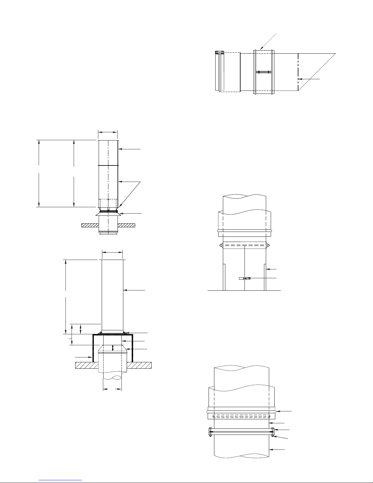
For diameters 26” thru 48” the chimney ue is terminated 9” (229)
below the required height for the installation (consult local codes).
A stack head adapter section is attached to the top section of
the chimney using a ange band and sealant. A closure ring is
attached to the ue to protect the annular space between the
inner and outer walls from rain. A plate support is located 6” (152)
below the top of the stack head adapter and PSW (Single Wall)
pipe, one size larger then the nominal chimney size, is attached
to it. The PSW pipe is equal in height to 4 times the chimney
diameter (See FIG. 50B). For guying requirements see TABLE
7 on Page 5.
Note: The structural steel supports for the stackhead are
provided by the installer. The stackhead assembly is intended
for use as a termination only for vertical discharge.
FIG. 50A – STACK HEAD ASSEMBLY
I.D. + 2” (51)
PSW PIPE
I.D. X 4
60” (1524) MAX FREE
STANDING HEIGHT
INTEGRAL STACK
HEAD ADAPTER
FIG. 51 - MITER CUT (MC)
CLOSURE BAND
BIRD SCREEN
APPLIANCE CONNECTORS
SINGLE WALL BOILER ADAPTER (SBA)
The single wall boiler adapter is the most commonly used
appliance connector. It is designed to clamp over a shank type
ue gas outlet. A thin layer of sealant, about 1” (25) wide is spread
on the end of the appliance outlet shank. Then the single wall
boiler adapter is placed around the shank covering the sealant.
The draw screw on the split tube is tightened to hold the single
wall boiler adapter in place (See FIG. 52).
FIG. 52 – SINGLE WALL BOILER ADAPTER
CLOSURE RING
FIG. 50B – STACK HEAD ASSEMBLY
I.D. + 2” (51)
I.D. X 4
9” (229)
SUPPORT STRUCTURE
TO ROOF- SUPPLIED
BY INSTALLER
6” (152)
I.D.
PSW PIPE
PLATE SUPPORT
STACK HEAD ADAPTER
CLOSURE RING
ROOF
MITER CUT (MC)
The miter cut is intended for use as a termination for a horizontal
discharge. It is designed to minimize the entry of rainwater
when installed in the proper orientation. Note that the miter cut
is a single wall part and requires a clearance of 18” (457) to
combustibles.
The miter cut is equiped with a birdscreen at the short side of
the miter (See FIG. 51). The miter must be installed so that the
long side of miter is on the top of the pipe to afford protection
from rain.
BOILER OUTLET SHANK
CLAMPING SCREW
The single wall boiler adapter is 6” (152) long. A 4” (102) long
variation is available on request.
FLANGE ADAPTER (FA)
The ange adapter is intended for use as a connection to a Class
125 or 150 ANSI pipe ange. This type of connection requires a
ange gasket and bolt set supplied by the installer. The gasket
and bolts are typically sold by pipe, valve and ttings houses as
an “NBG” set. FIG. 53 illustrates a typical installation.
FIG. 53 – FLANGE ADAPTER
CASING CLOSURE INCLUDED
FLANGE ADAPTER
FLANGE GASKET (BY OTHERS)
BOLT AND NUT (BY OTHERS)
APPLIANCE OUTLET
19
Page 20
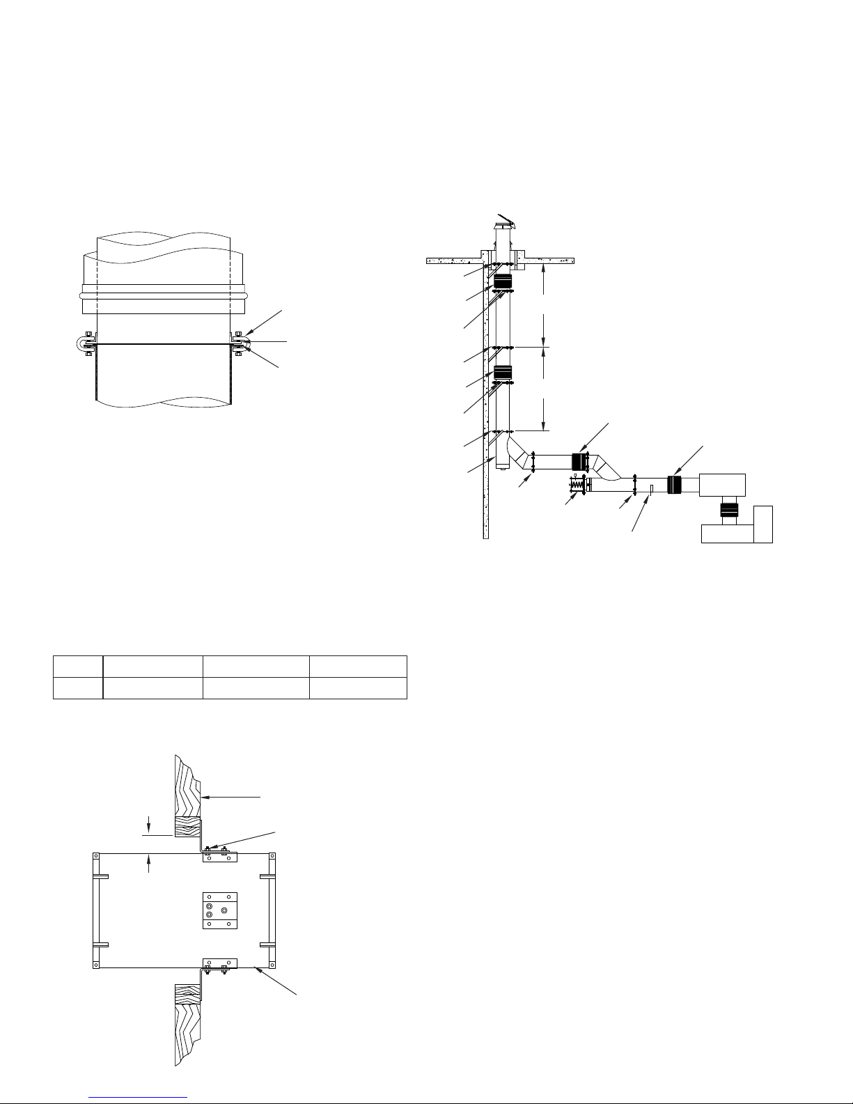
BOILER FLANGE ADAPTER (BFA)
The boiler ange adapter is used to connect PIC/IPIC pipe to
anged appliance outlets other than those with ANSI pipe anges.
Typical use includes boilers, water heaters and connection to
existing fabricated pipe. The adapter is designed to sandwich
the 1/2” inner pipe ange between the appliance outlet and the
boiler ange adapter (See FIG. 54). The boiler ange adapter is
shipped with beam clips used to clamp the BFA to the appliance
ange. The connection may also be drilled and bolted or welded
if desired.
FIG. 54 - BOILER FLANGE ADAPTER INSTALLATION
CLAMP
HALF RING
BOILER OUTLET FLANGE
WALL PENETRATOR (WP)
This part is used to allow PIC/IPIC pipe to pass through non-re
rated walls at reduced clearance. It consists of a 30” (762) long
thimble with mounting brackets. The wall penetrator is mounted
as follows:
1. Cut the opening in the wall. See chart below for opening
size.
2. Position the wall penetrator tube in the opening so it is
centered. Secure it to the wall with bolts or lag screws
(supplied.)
3. Install pipe so that it passes through the center of the wall
penetrator. Install lateral braces around the pipe casing.
Leave rings loose enough to slide along pipe.
4. Push the lateral rings into the wall penetrator centering the
tabs within the ends of the tube.
ENGINE EXHAUST SYSTEM PRECAUTIONS
Engine exhaust systems require extra attention to support and
protection detail due to the possibility of delayed fuel ignition in
the exhaust system. It is important that all turns are protected
as illustrated in FIG. 14, 16 & 18 or rigidly attached to structural
framing or walls. FIG. 56 illustrates some of the special
considerations that must be considered when designing an
engine exhaust system.
FIG. 56 – ENGINE EXHAUST CONSIDERATIONS
PLATE
SUPPORT
BELLOWS
JOINT
WALL
GUIDE
PLATE
SUPPORT
BELLOWS
JOINT
WALL
GUIDE
PLATE
SUPPORT
FIXED
TEE
IMPORTANT: When installed vertically, bellows joint must
not support weight of stack. Locate bellows joint near the
lowersideofxedsupportasshowninFIG.55.
The following components are primarily for use on engine or
turbine exhaust systems.
3” (76) MAX.
EXPANSION
3” (76) MAX.
EXPANSION
PLATE
SUPPORT
RELIEF
VALV E
BELLOWS JOINT
PLATE
SUPPORT
HALF
ANGLE
BELLOWS JOINT
MUFFLER
ENGINE
Model PIC & IPIC-1 IPIC-2 IPIC-4
“X” I.D. + 8” (203) I.D. + 10” (254) I.D. + 14” (356)
FIG. 55 - WALL PENETRATOR (WP)
COMBUSTIBLE WALLS
ATTACHED WITH 8D NAILS
4” MIN. (102)
OR #10 - 2” WOOD SCREWS
(4 PLACES)
WALL PENETRATOR
BELLOWS JOINT (BJ)
Note: Standard bellows joints require greater clearance to
combustibles that double wall components. See Table 9 for
standard single wall and optional double wall bellows joints
for clearances.
Bellows joints are recommended for vibration and expansion
movement. This type of movement is typically encountered in
diesel engine or turbine exhaust applications. FIG. 56 illustrates
typical bellows joint locations in a diesel engine exhaust system.
NOTE: Bellows Joints are required for expansion joints
in high pressure applications including engine or turbine
exhaust. Systems that use Bellows Joints are to use seal
clips (See TABLE 4 on Page 5) and additional joint sealant
per Page 23.
20
Page 21
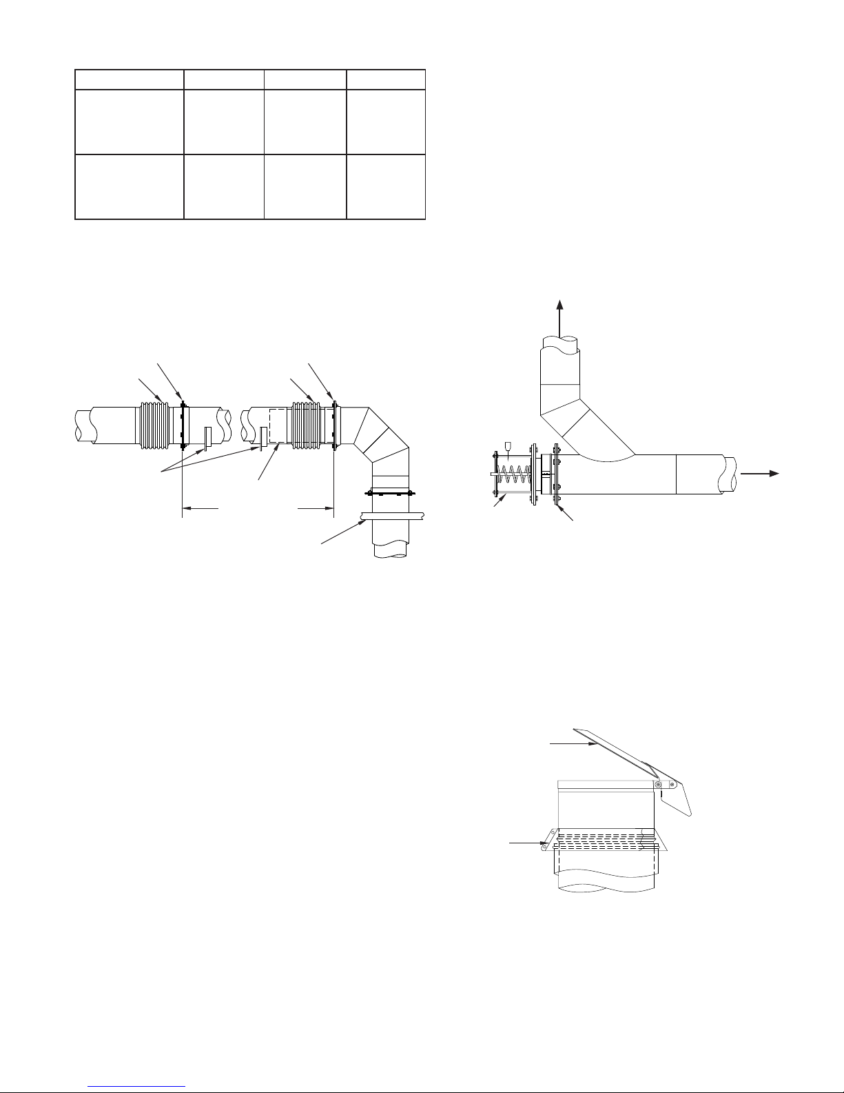
TABLE 9 - BELLOWS JOINT CLEARANCE
Location Size Single Wall Double Wall
Exterior
Combustible
Non-combustible
6” - 48”
6” - 18”
20” - 48”
18”
2”
4”
SEE
TABLE
1
Interior
Combustible
Non-combustible
6” - 48”
6” - 18”
20” - 48”
18”
2”
4”
SEE
TABLE
1
NOTE: P071 Sealant must be used for all joint connections
when Bellows Joints are required. For exterior installations,
sealant must be cured before exposure to moisture.
RELIEF VALVE (RV)
The relief valve is intended for use with diesel engines to
provide extra protection to the pipe in case of a delayed ignition
of unburned fuel in the exhaust system. It consists of a spring
loaded disk valve mounted on a ange adapter. The valve is
factory calibrated to open at 27 in. wc. The calibration nuts must
not be changed or the valve may not function correctly.
The relief valve must be supported independently of the rest of
the exhaust system. The best method to accomplish this is to
locate a plate support at the joint between the relief valve and
the adjacent tting. It is crucial that the plate support be properly
secured to building structure so that it can withstand the forces
generated in case of delayed fuel ignition (See FIG. 58).
FIG. 58 – RELIEF VALVE SUPPORT (RV)
FIG. 57 – BELLOWS JOINT LOCATION IN DIESEL ENGINE
EXHAUST SYSTEM
PLATE SUPPORT PLATE SUPPORT
BELLOWS
JOINT
HALF ANGLE
BELLOWS
JOINT
LINER
TOWARD VENT
3” (76) EXPANSION
MAXIMUM
APPLIANCE OUTLET
Bellows joints may be used in either horizontal or vertical
positions. It is imperative that the bellows joint be properly
supported and guided in either orientation. A bellows joint is
typically supported by a plate or wall support assembly on the
appliance end of the bellows and guided by a full angle ring or
wall guide on the exhaust end. The exhaust side guide should
be located approximately 6”-12” (152-305) from the downstream
end of the bellows joint.
IMPORTANT: When supporting high rise exhaust systems,
bellows joints must be located just below every xed
support to prevent compression at ambient temperatures
(See FIG. 57).
Good design indicates that any section of exhaust piping over
4’ (1.2m) between xed points be equipped with a bellows joint.
A bellows joint can compensate for up to 3” (76) of expansion.
The entire exhaust system should be examined to assure that
bellows joints are installed in pipe runs in which 3” (76) or less
of expansion is expected. For a method of calculating expansion
(See NOTE 3 on PAGE 11 under expansion joints).
For example, a 60-foot run (18.3m) of exhaust pipe handling
1000º F ue gas would produce 60ft/100 X 1000ºF/100 = 6” (152)
of expansion. This run would require 2 bellows joints.
The bellows joint is lined to minimize contact between the
bellows and exhaust gases. Thus, it cannot be used to correct
mis-alignment. The liner extends approximately 2” (51) past one
end of the bellows joint ange. This extension should always be
toward the downstream (exhaust) side of the system to avoid
becoming an obstruction for the shockwave in the event of a
delayed ignition incident in the exhaust system.
TO VENT
TO MUFFLER
RELIEF
VALV E
PLATE SUPPORT
(SECURE TO BUIDING)
METAL-FAB RECOMMENDS THAT ALL DIESEL ENGINE
EXHAUST SYSTEMS BE EQUIPPED WITH A RELIEF VALVE.
FLIP TOP (FT)
The ip top (FIG. 59) is designed to be installed either on a vertical
or horizontal exhaust. If installed on a horizontal termination, the
hinged side of the top must be oriented at the top of the pipe
keeping the counterweight up.
FIG. 59 – FLIP TOP (FT)
FLIP TOP
CLOSURE RING
USE OF VARIABLE LENGTH
Metal-Fab generally recommends the use of xed custom
lengths where standard lengths do not work for engine exhaust
systems (See Pages 10 and 11). If a variable length must be
used, the inner tube must be installed with the anged end
toward the engine. This allows an unobstructed ow path in
case of a delayed ignition occurrence.
21
Page 22

WEIGHT CALCULATIONS BY INSULATION THICKNESS FOR TABLE 4
PIC WEIGHT CALCULATIONS
Pipe IDI.D. x 0.8 =
lbs/ft
6 4.8 20 96 4 384 506.3
8 6.4 20 128 4 512 675.1
10 8 20 160 4 640 843.9
12 9.6 20 192 4 768 1012.7
14 11.2 20 224 4 896 1181.4
16 12.8 20 256 4 1024 1350.2
18 14.4 20 288 4 1152 1519.0
20 16 20 320 4 1280 1687.8
22 17.6 20 352 4 1408 1856.5
24 19.2 20 384 4 1536 2025.3
26 20.8 20 416 4 1664 2194.1
28 22.4 20 448 4 1792 2362.9
30 24 20 480 4 1920 2531.6
32 25.6 20 512 4 2048 2700.4
34 27.2 20 544 4 2176 2869.2
36 28.8 15 432 4 1728 2278.5
PipeIDI.D. x 0.95 =
lbs/ft
6 5.7 20 11 4 4 456 601.3
8 7.6 20 152 4 608 801.7
10 9.5 20 190 4 760 1002.1
12 11.4 20 228 4 912 1202.5
14 13.3 20 266 4 1064 1403.0
16 15.2 20 304 4 1216 1603.4
18 17.1 20 342 4 1368 1803.8
20 19 20 380 4 1520 2004.2
22 20.9 20 418 4 1672 2204.6
24 22.8 20 456 4 1824 2405.1
26 24.7 20 494 4 1976 2605.5
28 26.6 20 532 4 2128 2805.9
30 28.5 15 427.5 4 1710 2254.7
32 30.4 15 456 4 1824 2405.1
34 32.3 15 484.5 4 1938 2555.4
36 34.2 15 513 4 2052 2705.7
No. of ft
supported
ft. x lbs/ft =
lbs.
Safety
Factor
IPIC-1 WEIGHT CALCULATIONS
No. of ft
supported
ft. x lbs/ft =
lbs.
Safety
Factor
Test
lbs. x 1/.7584 =
lbs.
Test
lbs. x 1/.7584 =
lbs.
psi
psi
PipeIDI.D. x 1.05 =
lbs/ft
6 6.3 20 126 4 504 664.6
8 8.4 20 168 4 672 886.1
10 10.5 20 210 4 840 1107.6
12 12.6 20 252 4 1008 1329.1
14 14.7 20 294 4 1176 1550.6
16 16.8 20 336 4 1344 1772.2
18 18.9 20 378 4 1512 1993.7
20 21 20 420 4 1680 2215.2
22 23.1 20 462 4 1848 2436.7
24 25.2 20 504 4 2016 2658.2
26 27.3 20 546 4 2184 2879.7
28 29.4 15 441 4 1764 2325.9
30 31.5 15 472.5 4 1890 2492.1
32 33.6 15 504 4 2016 2658.2
34 35.7 15 535.5 4 2142 2824.4
36 37.8 15 567 4 2268 2990.5
IPIC-2 WEIGHT CALCULATIONS
No. of ft
supported
ft. x lbs/ft =
lbs.
Safety
Factor
22
Test
lbs. x 1/.7584 =
lbs.
psi
Page 23
IPIC-4 WEIGHT CALCULATIONS
PipeIDI.D. x 1.45 =
lbs/ft
6 8.7 20 174 4 696 917.7
8 11.6 20 232 4 928 1223.6
10 14.5 20 290 4 1160 1529.5
12 17.4 20 348 4 1392 1835.4
14 20.3 20 406 4 1624 2141.4
16 23.2 20 464 4 1856 2447.3
18 26.1 20 522 4 2088 2753.2
20 29 15 435 4 1740 2294.3
22 31.9 15 478.5 4 1914 2523.7
24 34.8 15 522 4 2088 2753.2
26 37.7 15 565.5 4 2262 2982.6
28 40.6 10 406 4 1624 2141.4
30 43.5 10 435 4 1740 2294.3
32 46.4 10 464 4 1856 2447.3
34 49.3 10 493 4 1972 2600.2
36 52.2 10 522 4 2088 2753.2
No. of ft
supported
ft. x lbs/ft =
lbs.
Safety
Factor
Test
lbs. x 1/.7584 =
lbs.
psi
THE INFORMATION ON THIS PAGE PERTAINS TO ALL APPLICATIONS
TABLE 3 - EXPECTED NUMBER OF TUBES PER JOINT
(P071 OR P077 SEALANT)
Pipe Diameter No. of Tubes Pipe Diameter No. of Tubes Pipe Diameter No. of Tubes
6” 0.20 22” 0.33 38” 1.00
8” 0.20 24” 0.50 40” 1.00
10” 0.20 26” 0.50 42” 1.00
12” 0.25 28” 0.50 44” 1.00
14” 0.25 30” 0.67 46” 1.20
16” 0.25 32” 0.67 48” 1.20
18” 0.33 34” 0.67
20” 0.33 36” 0.67
EXPECTED NUMBER OF TUBES PER JOINT FOR PRESSURE SEALS, IN ADDITION TO THE ABOVE
Pipe Diameter No. of Tubes Pipe Diameter No. of Tubes Pipe Diameter No. of Tubes
6” 0.60 22” 1.80 38” 3.60
8” 0.70 24” 2.10 40” 3.70
10” 0.90 26” 2.20 42” 3.80
12” 1.00 28” 2.40 44” 4.10
14” 1.10 30” 2.67 46” 4.30
16” 1.33 32” 2.90 48” 4.50
18” 1.55 34” 3.00
20” 1.67 36” 3.20
(P071 SEALANT)
23
Page 24

NOTES
P.O. Box 1138 • WICHITA, KANSAS 67201
[email protected] • www.metal-fabinc.com
(316) 943-2351 • FAX (316) 943-2717
24
©2016 Metal-Fab, Inc. Form No. L2592 11/16
9602
 Loading...