

Page 1

TABLE OF CONTENTS
SECTIONS DESCRIPTION PAGE
1.0 INTRODUCTION........................................................................................................ 1
2.0 RECEIPT AND STORAGE........................................................................................ 1
3.0 INSTALLATION ......................................................................................................... 2
3.1 Mechanical ............................................................................................................ 2
3.1.1 Vibrator Mounting..................................................................................... 3
3.2 Electrical ............................................................................................................... 4
3.2.1 Cable Connection .............................................................................. 4 & 5
3.2.2 Twin Vibrator Applications ...................................................................... 5
3.2.3 Thermistor Wiring....................................................................................... 5
4.0 OPERATION................................................................................................................ 5
4.1 Electrical................................................................................................................ 5
4.2 Mechanical ............................................................................................................ 6
4.3 Start-up.................................................................................................................. 6
5.0 MAINTENANCE .......................................................................................................... 7
5.1 Routine Maintenance ............................................................................................ 7
5.2 Bearing Lubrication................................................................................................ 7
5.2.1 Models BL 03- BL 20, BL 24/25-8/2, -7.5/4, and -4/6 .............................. 7
5.2.2 Models BL 24 - 30 (except BL 24/25-8/2, -7.5/4, and -4/6) ..................... 7
5.2.3 Models BL 40 to BL 75.............................................................................. 8
5.3 Vibrator Overhaul .................................................................................................. 8
6.0 TROUBLESHOOTING ............................................................................................. 10
6.1 Vibrator Is Not Running....................................................................................... 10
6.1.1 Verify Correct Voltage............................................................................. 10
6.1.2 Verify Terminal Connections................................................................... 10
6.2 Vibrator starts but will not continue to run ................................................. 10 & 11
6.3 Vibrator current consumption is in excess of Table A-1 ratings.......................... 11
6.4 Vibrator surface temperature is excessive............................................................ 11
6.5 Noisy vibrator.............................................................................................. 11 & 12
6.6 Vibrator runs too slowly (does not reach synchronous speed) ............................ 12
6.7 Twin vibrators not synchronizing......................................................................... 12
FIGURES DESCRIPTION
PAGE
Figure 1 Illustration of Vibrator Out of Balance Weight ............................................................. 2
Figure 2 Terminal box connections for 460 Volt, 3 Phase, 60 Hz operation............................... 5
Figure 3 Terminal box connections for 230 Volt, 3 Phase, 60 Hz operation............................... 5
Figure 4 Proper Thermistor Winding........................................... ................................................. 6
i
Page 2

TABLE OF CONTENTS (Cont'd)
TABLES DESCRIPTION
Table 1 Vibrator Internal Fastener Torque Values and Tension....................................................... 3
Table 2 Vibrator Mounting Bolt Torque Values (NC Threads) ....................................................... 4
Table 3 Bearing Relubrication Intervals and Amounts ...................................................................... 9
Table A-1 Vibrator No Load, Full Load, & Starting Currents for 3 Phase, 60 Hz ............................. A-1
Table A-2 Vibrator Normal Resistance Readings............................................................................... A-2
Table A-3 Vibrator Parts List For Models BL 03 to BL 25 ............................................................... A-3
Table A-4 Vibrator Parts List For Models BL 30 to BL 75 ............................................................... A-4
Table A-5 Factory Specified Vibrator Bearings ................................................................................. A-5
PAGE
ii
Page 3

1.0 INTRODUCTION
The Invicta L Series Vibrators are Heavy Duty Industrial Rotary Electric Vibrators. Their
similarity in appearance to conventional industrial electric motors should not mislead the user into
servicing them as standard electric motors.
The stator frame castings, cylindrical roller bearings, bearing housings, rotors, stators and
fasteners are of special construction and tolerance fits. This is because the Invicta is a "Vibrating
Machine" and only original factory parts should be used. Furthermore, to achieve satisfactory
results, troubleshooting and repairs should be performed by trained personnel experienced with
Invicta Vibrators.
The Hindon facility in Charleston, SC, has personnel fully qualified and is stocked to
perform all required service, retrofit and rebuilding.
• Please read this manual carefully.
• Use only Original Equipment Manufacturer (O.E.M.) parts (including specified bearings).
• Use only personnel trained in the repair of Invicta Vibrators.
As a point of interest, the L Series model designation includes an indication of maximum centrifugal force
output. Actual force is 100 times the centrifugal force figure stated.
Example: Model B L 20 - 5 / 4
Pole Speed (i.e. 4 = 1800 RPM)
Centrifugal Force (kg) ÷ 100
Frame Size
Series
Base Mounted
2.0 RECEIPT AND STORAGE
Each machine is thoroughly inspected and tested before leaving the factory, and every care
is taken to ensure safe transit to destination. Damage may, however, occur during shipment.
Therefore, the vibrator should be inspected upon receipt and the shaft rotated by hand. Any damage
should be reported immediately to the carrier. Vibrators not intended for immediate use should be
stored in a dry temperate atmosphere, free from vibration. Under these conditions, the machine may
be stored for approximately 18 months.
Extended Storage
For vibrators requiring storage beyond 18 months, please contact Hindon Corporation for
specific instructions.
1
Page 4
3.0 INSTALLATION
3.1 Mechanical
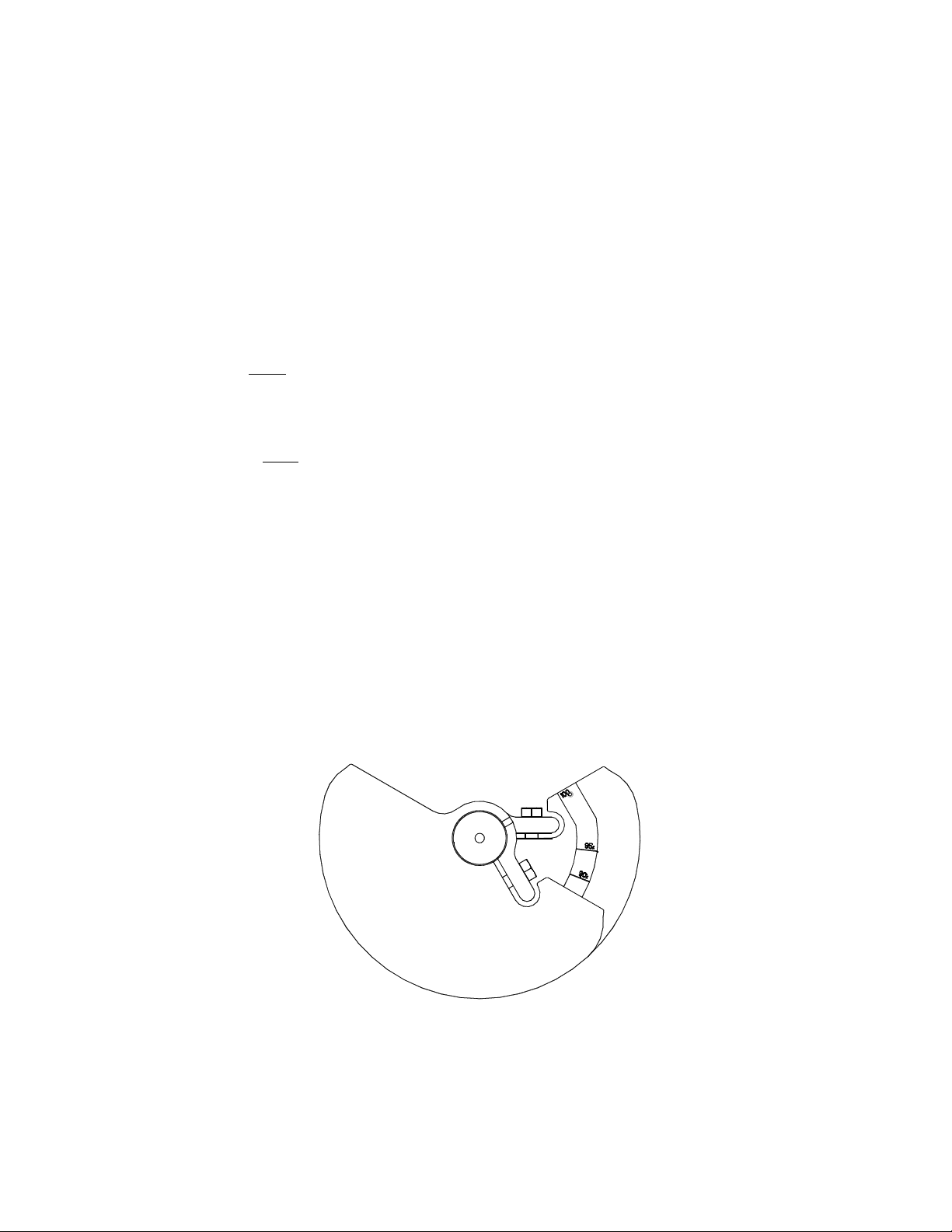
Ensure shaft rotates freely by hand prior to mounting. This will require removing one end
cover to access the out-of-balance (O.B.) weights. Unless otherwise requested, vibrators are supplied
with the O.B. weights set to give a maximum centrifugal force output. To adjust O.B. weights to
the required force output, follow these steps and refer to Figure 1.
1) Remove end covers.
2) Adjust inner weights on each side of shaft extension to reduce centrifugal force output while
outer weights remain fixed on the shaft. Please note: For models BL 03-20 out-of-balance
weights can be adjusted by inner or outer weight, provided both ends are adjusted the same.
3) Weights must be adjusted equally on each side of the vibrator. The scale on the inner O.B.
weights is stated as a percentage of the maximum rated centrifugal force (CF) output.
Example: BL 30-25/4 is factory set at a maximum 5500 lbs. CF (i.e., 100 percent O.B.
weight scale). Assume you need to achieve a 3575 lbs. CF output. Adjust the O.B. weights
on each side to 65 percent (0.65 * 5500 = 3575). The percentage scale attached to the inner
O.B. weights allows for an infinite adjustment between the range indicated. Care should be
taken to properly re-torque O.B. weight clamp screws (in accordance with internal fastener
torque values in Table 1).
4) Ensure end cover O-rings are properly positioned on bearing housing flange prior to refit of
end covers. (If O-rings are dry, an application of petroleum jelly or silicone spray will ease
refit of the end covers and reduce the potential of O- ring "pinching").
Figure 1: Illustration of Vibrator Out-of-Balance Weight
Table 1: Vibrator Fastener Torque Values
2
Page 5
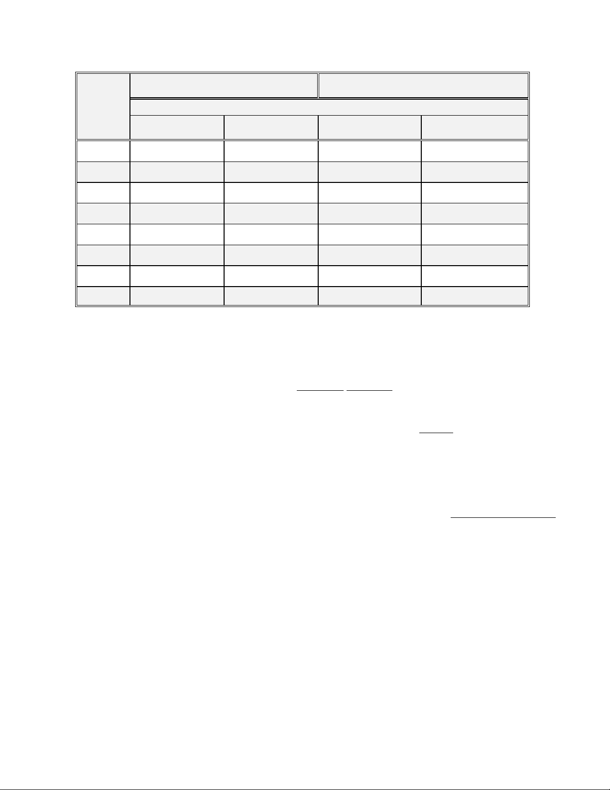
INTERNAL FASTENERS
SIZE
M5 6 - 5 -
M6 11 8 8 8
M8 25 20 20 20
M10 50 41 41 41
M12 94 71 71 71
M16 228 178 130 178
M20 - 348 - 348
M24 - 602 361 602
(EXCLUDING O/B WEIGHTS)
SOCKET HEAD
CAP SCREWS
HEX HEAD
BOLTS
* Values are for factory supplied fasteners.
3.1.1 Vibrator Mounting
O/B WEIGHT FASTENERS
* TORQUE (LBS-FT)
SOCKET HEAD CAP
SCREWS
HEX HEAD
BOLTS
It is recommended that the fasteners (bolts, nuts and hardened flat washers) be a minimum
of grade 5 and a maximum of grade 8. It is extremely important to follow the guidelines below for
safe and proper vibrator mounting:
1) Vibrator must be mounted upon a flat or machined, rigid base. NOTE: If the base is not flat
or is able to flex under load, the vibrator can come loose.
2) Ensure that no paint or other foreign matter exists on any of the mating surfaces being bolted;
either at the washer seatings or on the vibrator foot or vibrator mounting beams.
3) For all vibrator models, the mounting bolts must be provided with hardened flat washers
under the bolt heads and under the nuts. Ensure that entire outside diameter of washer seats
within the spot facing of the mounting hole.
4) The nuts must be pre-tightened until all the mating surfaces are brought into contact. The
nuts must then be tightened using a torque wrench in accordance with torque values as
detailed in Table 2. (Use a criss-cross pattern for torquing sequence).
5) After approximately 30 minutes of initial vibrator operation, the unit should be switched off
and all mounting bolts checked and re-tightened with a torque wrench to the values stated
in Table 2. After one to two hours of operation, this tightening procedure should again be
repeated. If any loosening of the mounting bolts has occurred during this initial period,
check flatness of mounting plate and vibrator base to ensure a proper "seating" of the two
surfaces.
3
Page 6

(
)
Table 2: Vibrator Mounting Bolt Torque Values (NC Threads)
* TORQUE (BY NUT)
VIBRATOR MODEL
BL 03-1/2, 0.5/4 .33" and .35” 5/16" – 18 18 28
BL 05-2/2, -1/4, -2/4
BL 15-3.5/2, -3/4
MOUNTING
HOLE
(Diameter)
.41" 3/8" – 16 31 43
BOLT
SIZE
(Diameter) GRADE 5 GRADE 8
LBS-FT
BL 20-5/2, 5/4
BL 24/25-8/2, 10/2, 13/2, 7.5/4, 11/4, 14/4,
4/6, 8/6, 11/6
BL 30-16/2, 20/2, 18/4, 25/4, 14/6, 18/6,
23/6, 7.5/8, 10/8
BL 40-30/2, 40/2, 35/4, 27/6, 35/6, 17/8
BL 45-45/4, 42/6, 50/6, 24/8, 35/8
BL 50-50/2, 55/4, 65/4, 75/4, 60/6, 75/6,
45/8, 57/8
BL 60-95/4,105/4, 90/6, 105/6, 70/8, 90/8
BL 75-130/4, 150/6, 185/6, 150/8 1.29" 1 1/4" - 7 1105 1792
.54" ½" - 13 75 106
.66”
1.02" 1" - 8 583 825
5/8" - 11 150 209
* Values are for non-lubricated, unplated carbon steel fasteners. Please contact Hindon for further
information if other types of fasteners are to be used.
3.2 Electrical
It is a good policy, prior to vibrator mounting, to measure winding insulation resistance by
meggering; this reading should be greater than 1 megohm. If the winding has become damp, resulting in
an unacceptable megger reading, the stator winding must be thoroughly dried and re-meggered and a
satisfactory reading obtained prior to vibrator installation. In the event of an unacceptable megger reading,
please contact Hindon Corporation directly and advise reading along with vibrator model and serial
number. Most vibrators are dual voltage 230/460 (verify electrical data by reviewing the vibrator
nameplate) and are normally factory configured for 460 Volt operation. For 575 Volt winding “Star”
connection as shown in figure 2 (pg. 5) would apply. Configuring for 230 Volt operation is easily
accomplished by adjustment of the link plates (buss bars) on the terminal block. For specific terminal box
connections, please refer to Figures 2 and 3 on the following page. For details on wiring of thermistors
that are supplied in Invicta models BL 24 – BL 75, please refer to section 3.2.3
3.2.1 Cable Connection
Attach flexible 4-conductor type "SO" cord (allowing for "drip or vibration loop") and
suitable watertight connector to terminal box entry. NOTE: For added safety, electrical power cord must
be installed with sufficient slack to allow vibration, and so that condensation will "drip" from bottom of
loop.
4
Page 7

STAR - 460 or 575 Volts DELTA - 230 Volts
W2 U2 V2
V1 W1
U1
L-2 L -3
L-1
T2
T1
Figure 2: Terminal box connections for 460
or 575 Volt 3 Phase, 60 Hz
W2
U1
L-1
Figure 3: Terminal box connections for 230
Volt, 3 Phase, 60 Hz operation.
V2U2
L-2V1L-3
T2
T1
W1
operation.
Ensure foam packing is in place to protect electrical leads from vibration. Be sure to fit the
rubber gasket or o-ring into place prior to installing the terminal box lid to ensure a watertight seal.
Proper thermal overload selection for the vibrator's starter should be based on either:
1) Full load current rating as indicated on the unit's nameplate; or
2) Actual operating current (if lower).
(For further technical specifications on vibrator electrical data, please refer to APPENDIX A - Tables
A-1 and A-2).
3.2.2 Twin Vibrator Applications
When twin vibrators are used on one machine, it is imperative that both vibrators start and
stop at the same time. If one vibrator has an overload, both must shut off at the same time. One
push-button should control both starters.
3.2.3 Thermistor Wiring
Invicta vibrators (models BL 24 – BL 75) are equipped with PTC (Positive Temperature
Coefficient) sensors, i.e., thermistors, installed in each winding phase. Utilizing this feature is highly
recommended. These sensors (to be used in conjunction with an electronic control module) will provide
motor protection against thermal overheating. The control module interlocks the thermistors within the
windings to the starter control circuit. Please refer to Figure 4 on the following page for proper connection
of this safety feature.
5
Page 8

ONE (1) SENSOR PER PHASE
TERMINATED AT VIBRATOR
4.0 OPERATION
4.1 Electrical
TERMINAL BOX
VIBRATOR
SENSOR INPUTS
INTERNAL CONTACT SHOWN IN
"TRIPPED" CONDITION
1
2
3
C
CONTROL MODULE TO SENSOR
WIRING DIAGRAM
Figure 4: Proper Thermistor Wiring
4
5
6
7
8
120 VAC INPUT
RESET SWITCH
TO CONTROL CIRCUIT
Prior to operation, ensure that the electrical voltage is correct and that feed cable(s) to the
vibrator(s) are correctly sized for the load and mechanical requirements. The method of starting
should be direct, on-line for all vibrator sizes. Unless using an inverter or soft start system, a
push button starter with thermal overloads is recommended.
4.2 Mechanical
Prior to operation, confirm that all mounting bolts are tight and properly torqued. It is
recommended that all mounting fasteners be checked and re-tightened within several hours after
initial operation to ensure a secure mounting.
4.3 Start-up
Upon completion of sections 4.1 and 4.2, the vibrator can now be started.
After initial start-up, verification of proper thermal overload (heater) selection should be
performed by measuring actual running current of the vibrator. Re-size heater elements if necessary
for proper protection. Periodically re-torque mounting bolts during routine maintenance periods.
In the event of any start-up problems, please refer to SECTION 6 - TROUBLESHOOTING
.
6
Page 9

5.0 MAINTENANCE
5.1 Routine Maintenance
Routine maintenance deals predominantly with the proper lubrication of the vibrator
bearings. The lubrication intervals and amounts vary greatly depending on the vibrator model and
are further affected by outside factors such as duty cycle, ambient temperatures and operating
environment.
5.2 Bearing Lubrication
5.2.1 Models BL 03 to BL 20, BL 24/25-8/2, 7.5/4 and 4/6
Relubrication is not applicable since these units are manufactured with prelubricated
sealed ball bearings, and as such, are lubricated for the life of the bearing.
5.2.2 Models BL 24 – BL 30 (Except BL 24/25-8/2, 7.5/4 and 4/6)
Vibrators in this model range are not typically provided with external grease nipples.
The following steps should be carried out for proper bearing relubrication.
1) Ensure vibrator has been properly disconnected from the electrical power source prior to
proceeding.
2) Remove both end covers.
3) Remove the O.B. weights from each side of the shaft extension, taking care to first remove
shaft snap rings. Also, be sure to mark the current weight setting positions prior to removal
to ensure proper centrifugal force upon reassembly.
4) Remove both bearing housings (which contain the bearing outer races). The inner races
remain on the rotor shaft.
5) Bearing rollers and cages will now be exposed. Using a clean cloth, remove as much old
grease as possible and add additional grease as necessary by lightly "smearing" into the roller
cavities.
6) The factory recommended grease for Invicta Vibrators is: EXXON - UNIREX N2 or N3.
Do not mix grease types without first checking with supplier to ensure they are compatible.
(If mixing of grease is unavoidable, use only lithium complex alternatives.) Please refer to
Table 3 (page 9) for determining relube amounts and intervals.
7) Re-assemble vibrator in reverse order of disassembly. Ensure that all fastener threads have
been coated with Loctite #242 thread locking compound and are properly re-torqued to the
values listed in Table 1 (page 3).
7
Page 10

5.2.3 Models BL 40 to BL 75
Vibrators in this range have grease nipples fitted as standard. Recommended grease type is
EXXON-UNIREX N2 OR N3. Do not mix grease types without first checking with supplier to
ensure they are compatible. (If mixing of grease is unavoidable, use only lithium complex
alternatives.) Please refer to Table 3 (page 9) for determining relube amounts and intervals. Ensure
that grease nipples are clean to prevent introducing contamination into bearings. Overgreasing
causes overheating of the bearings and must be avoided. Grease cavities should never be filled
above one third of their capacity. It is essential that periodically old grease is removed and the
bearings thoroughly cleaned and repacked with new grease.
5.3 Vibrator Overhaul
Vibrator overhaul is dependent on actual use and operating conditions. It is
recommended that the vibrator be disassembled and thoroughly cleaned every 9 - 18 months. If
the vibrator has been "re-lubricated" more than 6 times or is operating under severe conditions,
then it will be necessary to overhaul the unit more frequently. Due to the mechanical tolerances
and specific reassembly procedures involved with these vibrator repairs, it is recommended that
vibrators requiring full overhaul be shipped to Hindon Corporation. This is to ensure that factory
qualified service and O.E.M. quality replacement parts will be used.
8
Page 11

Table 3: Bearing Relubrication Intervals and Amounts
Relub. Interval *
Vibrator Model
2 Pole
BL 24/25-10/2 1600 0.2 0.4
BL 24/25-13/2 1400 0.3 0.6
BL 30 ALL 700 0.4 0.9
BL 40-30/2 650 0.5 1.2
BL 40-40/2 600 0.7 1.9
BL 50-50/2 200 0.6 2.8
4 Pole
BL 24/25-11/4 3500 0.2 0.4
BL 24/25/-14/4 3300 0.3 0.6
BL 30 ALL 3100 0.5 1.1
BL 40-35/4 2700 0.6 1.4
BL 45-45/4 2200 0.8 2.1
BL 50-55/4 1800 1.1 3.2
BL 50-65/4, -75/4 1600 1.3 3.9
BL 60 ALL 800 1.7 5.6
BL 75-130/4 350 1.3 7.1
6 Pole
BL 24/25-8/6 5800 0.2 0.4
BL 24/25-11/6 4800 0.3 0.6
BL 30 ALL 5000 0.5 1.1
BL 40 ALL 4300 0.7 1.4
BL 45 ALL 4100 0.9 2.1
BL 50-60/6 3800 1.1 3.2
BL 50-75/6 3400 1.3 3.9
BL 60 ALL 2600 1.9 5.6
BL 75 ALL 1800 2.3 7.1
8 Pole
BL 30 ALL 7000 0.5 1.1
BL 40-17/8 6500 0.7 1.4
BL 45 ALL 6000 0.9 2.1
BL 50-45/8 5500 1.1 3.2
BL 50-57/8 5000 1.1 3.9
BL 60 ALL 4500 2.1 5.6
BL 75-150/8 3000 2.3 7.1
(Hours)
Grease Amount
Per Brg. (Ounces)
Initial Grease Fill
Per Brg. (Ounces)
* Relubrication intervals are based on continuous operation in ambient temperatures up to 68°F
(20° C) and should be reduced for increases in ambient temperature as follows: 77°F (25° C) x
.8, 86°F (30° C) x 0.65, 95°F (35° C) x 0.5, 104°F (40° C) x 0.4. Above 104°F (40° C) consult
our Technical Department.
Factory recommended grease for Invicta vibrators is EXXON UNIREX N2 or N3.
NOTE: The above relubrication intervals are for guidance only
and may be shortened or
lengthened, if necessary, in view of actual field experience by the end user.
9
Page 12

6.0 TROUBLESHOOTING
6.1 Vibrator Is Not Running
6.1.1 Verify Correct Voltage
1) Verify that the correct voltage is present at the vibrator terminal box; if correct proceed to
section 6.1.2, if not:
2) Verify that main fuses or circuit breakers are "ON".
3) Verify that L-1, L-2 and L-3 terminals of the motor starter(s) are energized.
4) Verify that the motor starter is functioning correctly and that terminals T-1, T-2 and T-3 are
energized.
5) Verify that no failure exists in the flexible cable leading to the vibrator terminal box.
6.1.2 Verify Terminal Connections
If section 6.1.1 is correct, ensure that vibrator terminal connections are correct.
1) Verify that the terminal connections are correct by referring to Figures 2 and 3, if not:
NOTE: Vibrators are normally supplied with dual voltage, 230/460 Volt, 3 Phase, 60 Hz,
windings and must be field connected for a specific voltage. Units are normally connected
for high voltage (460 Volt) from the factory. Check vibrator nameplate data to verify
voltage; some special vibrators are supplied with single voltage windings.
2) Verify that the stator windings are not "open" or,
3) Test windings, to verify they are not "shorted internally" or "shorted to ground".
NOTE: The above tests can be performed with instruments such as resistance measuring
devices and/or a megger.
If sections 6.1.1 and 6.1.2 have been performed and vibrator is still inoperable, please contact
Hindon Corporation for further assistance.
6.2 Vibrator starts but will not continue to run
1) Verify correct motor starter operation:
a) Verify correct "heater" selection based on full load current from vibrator nameplate
or Appendix A - Table A-1.
10
Page 13

2) If motor starter heaters are correctly sized but motor starter circuit overloads and trips (and supply
voltage is correct), then check:
a) The vibrator mounting bolts and ensure they are properly torqued. Refer to Table 2.
b) The vibrator mounting beam and other vibrated mass structures to ensure that they
are not flexing, bending or cracked. This can lead to resonant vibrations and cause
vibrator "overloading".
c) That the vibrating equipment is free to vibrate, (i.e., support springs in working order,
no chutes touching or welded to live frame). This will cause vibrator overloading
and "off" motion.
3) Refer to section 6.1.2.
6.3 Vibrator current consumption is in excess of Table A-1 ratings
1) See section 6.2, steps 2a), 2b) and 2c), if not correct:
2) Verify that vibrator centrifugal force output is adequate for the application. This is
particularly important on bin vibrator applications.
3) Reduce vibrator centrifugal force setting to reduce current consumption.
4) Has vibrator been over-lubricated? See SECTION 5.2 - Bearing Lubrication for the proper
lubrication procedure.
6.4 Vibrator surface temperature is excessive
Important: Please note that this is a vibrating machine which does operate at higher surface
temperatures than standard industrial electric motors. If vibrator surface temperature is in excess of
185° F.
1) Record ambient temperature and advise Hindon (external fan cooling may be needed to cool
the vibrator and reduce the risk of failure).
a) Verify section 6.3. steps 1 thru 4.
b) Check that rotor shaft turns freely by hand and bearings are not binding. CAUTION:
Always ensure electrical power is de-energized prior to handling rotor shaft with
hands.
11
Page 14

6.5 Noisy vibrator
NOTE: Vibrating machines are inherently louder than industrial motors.
1) Check for loose or failed vibrator mounting fasteners.
2) Check for loose end cover fasteners and internal fasteners.
3) Check for loose O.B. weight clamping bolts. CAUTION: Always ensure electrical power
is de-energized prior to handling rotor shaft with hands.
4) Check for failed bearing(s).
6.6 Vibrator runs too slowly (does not reach synchronous speed)
1) Verify that terminal box connection is for correct voltage (i.e., that it is not set for 460 Volt
and line is 230 Volt). Refer to Figures 2 and 3.
2) Verify that line voltage is not too low.
3) Verify that line frequency is as vibrator nameplate specifies (this normally applies to field
generator operated equipment only).
4) Verify that rotor shaft turns freely. CAUTION: Always ensure electrical power is de-
energized prior to handling rotor shaft with hands.
6.7 Twin vibrators not synchronizing
1) Verify that both units are energized.
2) Verify that the vibrators are connected so that they will contra-rotate (opposite rotation).
3) Verify that the O.B. weights are set the same on each side and on both vibrators.
4) Verify that the vibrator mounting beam is rigid and not flexing excessively when operating.
Also, in the case of equipment such as feeders and screens, be sure that no "off motion"
exists on the live frame.
12
Page 15

APPENDIX A
Additional Vibrator Specification Tables and Parts Lists
Page 16

Table A-1: Vibrator No Load, Full Load & Starting Currents for 3 Phase, 60 Hz
230 Volt 460 Volt 575 Volt
Vibrator
Model
Watts
NLC FLC SC NLC FLC SC NLC FLC SC
2 Pole 3456 RPM 60 Hz
BL 03-1/2 60 0.18 0.28 2.7 0.13 0.17 1.4 0.12 0.14 1.1
BL 05-2/2 120 0.32 0.53 5.2 0.23 0.31 2.6 0.21 0.27 2.1
BL 15-3.5/2 250 0.32 0.93 5.2 0.23 0.5 2.6 0.21 0.41 2.1
BL 20-5/2 340 0.55 1.26 9.8 0.4 0.69 4.9 0.35 0.57 3.9
BL 24/25 ALL 500 0.88 1.88 17.8 0.64 1.05 8.9 0.57 0.87 7.1
BL 30 ALL 1100 0.9 3.6 40 0.64 1.8 20 0.6 1.5 16
BL 40 ALL 1500 1.2 4.9 61 0.9 2.5 30 0.8 2.0 24
BL 50-50/2 4000 2.7 11.4 129 1.9 5.9 64 1.6 4.7 51
4 Pole 1728 RPM 60 Hz
BL 03-0.5/4 35 0.22 0.28 1.4 0.16 0.18 0.7 0.14 0.16 1.1
BL 05 ALL 110 0.39 0.62 2.9 0.28 0.37 1.4 0.25 0.32 2.1
BL 15-3/4 175 0.65 1.1 4 0.47 0.64 2 0.41 0.54 2.1
BL 20-5/4 250 0.94 1.46 6.3 0.68 0.88 3.1 0.58 0.73 3.9
BL 24/25 ALL 500 1.23 2.08 15.1 0.89 1.22 7.6 0.78 1.03 7.1
BL 30 ALL 1150 2.1 3.9 42 1.5 2.2 21 1.3 1.9 17
BL 40-35/4 1800 2.6 6.0 56 1.9 3.3 28 1.7 2.7 22
BL 45-45/4 2685 4.0 8.5 99 2.9 4.8 50 2.7 4.0 40
BL 50-55/4 3350 4.4 10.3 129 3.2 5.7 64 2.9 4.7 51
BL 50-65/4, 75/4 4800 5.1 14.2 153 3.7 7.6 76 3.4 6.3 61
BL 60 ALL 7750 5.6 21.8 330 4.1 11.3 165 3.5 9.1 132
BL 75-130/4 10250 6.6 28.3 388 4.8 14.6 194 4.2 11.8 155
6 Pole 1152 RPM 60 Hz
BL 24/25 ALL 510 1.56 2.43 12.2 1.12 1.46 6.1 0.95 1.21 4.9
BL 30 ALL 900 3.2 4.3 26 2.3 2.7 13 2.1 2.4 10
BL 40 ALL 1800 4.9 7.5 43 3.5 4.6 22 3.2 3.9 17
BL 45 ALL 2310 6.5 9.3 76 4.7 5.8 38 4.3 5.0 31
BL 50 ALL 4000 7.6 13.6 106 5.5 7.9 53 5.0 6.7 42
BL 60 ALL 6200 7.6 18.2 188 5.5 10.0 94 5.3 8.5 75
BL 75 ALL 10000 11.6 29.4 400 8.4 16.0 200 7.5 13.2 160
8 Pole 864 RPM 60 Hz
BL 30 ALL 500 2.7 3.3 18 1.9 2.2 9 1.7 1.9 7
BL 40-17/8 1100 3.7 5.3 23 2.7 3.3 12 2.4 2.8 9
BL 45 ALL 2000 6.5 8.9 40 4.7 5.6 20 4.2 4.9 16
BL 50 ALL 3300 8.7 12.8 96 6.3 7.8 48 5.8 6.9 38
BL 60 ALL 4900 14.1 19.3 170 10.2 12.1 84 9.5 10.8 67
BL 75-150/8 7750 17.8 31.0 216 12.8 18.1 108 12.1 15.8 86
Note: * 575 Volt upon special request (Standard units are 230/460V, 3 Phase, 60 Hz)
A-1
Page 17

Table A-2: Vibrator Normal Resistance Readings
Vibrator Model
Resistance (OHMS per line)
230 Volt 460 Volt
2 Pole
BL 03-1/2 70.7 212
BL 05-2/2 36.8 110
BL 15-3.5/2 36.8 110
BL 20-5/2 17.1 51.2
BL 24/25 ALL 7.6 22.8
BL 30 ALL 2.7 8.0
BL 40 ALL 1.4 4.2
BL 50-50/2 0.3 0.9
4 Pole
BL 03-0.5/4 113 340
BL 05 ALL 53.5 160.4
BL 15-3/4 36 108
BL 20-5/4 21.7 65.2
BL 24/25 ALL 7.5 22.6
BL 30 ALL 2.72 8.2
BL 40-35/4 1.60 4.8
BL 45-45/4 0.75 2.24
BL 50-55/4 0.47 1.40
BL 50-65/4, -75/4 0.35 1.04
BL 60 ALL 0.13 0.40
BL 75-130/4 0.11 0.32
6 Pole
BL 24/25 ALL 11.4 34.2
BL 30 ALL 3.87 11.6
BL 40 ALL 1.80 5.40
BL 45 ALL 0.89 2.68
BL 50 ALL 0.49 1.46
BL 60 ALL 0.19 0.58
BL 75 ALL 0.15 0.44
8 Pole
BL 30 ALL 5.53 16.6
BL 40-17/8 4.13 12.4
BL 45 ALL 1.87 5.6
BL 50 ALL 0.51 1.52
BL 60 ALL 0.23 0.70
BL 75-150/8 0.17 0.56
A-2
Page 18

Table A-3: Vibrator Parts List for Models BL 03 to BL 25
Part # Description Quantity
1 Bearing Housing 2
2 End Cover 2
3 O/B Weight Assembly 1 set
4 Bearing 2
5 Rotor Shaft Assembly 1
6 Terminal Box Sealing Ring (Models BL 05 -BL 25) 1
6 Terminal Box Gasket (Model BL 03) 1
7 Sealing Ring – End Cover 2
8 Stator Frame 1
9 Stator Unit – 3 Phase 1
10 Terminal Block 1
11 Terminal Box Lid 1
12 Terminal Box Packing 1
13 Tolerance Ring (Model BL 24 ONLY) 2
ADVISE VIBRATOR MODEL, SERIAL NUMBER,
PART NUMBER, AND DESCRIPTION OF PART
WHEN ORDERING REPLACEMENT PARTS.
1
7
2
11
6
12
10
8
13
9
4
5
3
EXPLODED VIEW – BL 03 TO BL 25
A-3
Page 19

Table A-4: Vibrator Parts List for Models BL 30 to BL 75
Part # Description Quantity
1 Bearing Housing 2
2 Bearing Housing Cap 2
3 End Cover 2
4 Sealing Ring 2
5 O.B. Weight Assembly 1 set
6 Roller Bearing 2
7 Rotor Shaft Assembly 1
8 Sealing Ring - Terminal Box (BL 30 thru 50) 1
8 Gasket - Terminal Box (BL 60 & 75) 1
9 Sealing Ring – End Cover 2
10 Sealing Ring – Bearing Housing 2
11 Stator Frame 1
12 Stator Unit – 3 Phase 1
13 Terminal Block 1
14 Terminal Box Lid 2
15 Terminal Box Packing 1
ADVISE VIBRATOR MODEL, SERIAL NUMBER,
PART NUMBER, AND DESCRIPTION OF PART
WHEN ORDERING REPLACEMENT PARTS.
13
6
2
14
8
15
10
12
1
4
7
11
3
9
EXPLODED VIEW - BL 30 TO BL 75
NOTE: (External grease fittings are not provided on Model BL 30)
5
A-4
A-4
Page 20

Table A-5: Factory Specified Vibrator Bearings
Vibrator Model Hindon Part # Weight (lbs.)
BL 03-1/2 PSN 364/4 0.09
BL 05 ALL PSN 1631/5 0.33
BL 15-3.5/2 PSN 1631/7 0.70
BL 15-3/4 PSN 1631/6 0.46
BL 20-5/2 PSN 1631/9 1.26
BL 20-5/4 PSN 1631/8 0.92
BL 24 & BL 25-8/2, -7.5/4, -4/6 PSN 364/10 1.87
BL 24 & BL 25-10/2, -11/4, -8/6 PSN 843/1 1.17
BL 24 & BL 25-13/2, -14/4, -11/6 PSN 843/2 1.58
BL 30 ALL PSN 843/3 2.84
BL 40-30/2, 35/4, 27/6, 35/6, 17/8 PSN 843/4 4.91
BL 45 ALL, BL 40-40/2 PSN 843/5 7.28
BL 50-50/2, 55/4, 60/6, 45/8 PSN 843/6 10.89
BL 50-65/4, 75/4 PSN 755/5 16.79
BL 50-75/6, 57/8 PSN 843/7 15.07
BL 60 ALL PSN 755/6 29.26
BL 75 ALL PSN 755/9 40.92
A-5
 Loading...