

Page 1
Better-Weigh_ Feeders
Installation and Operating Instructions
Metalfab, Inc. Vernon, NJ 07462 Phone (973)764-2000 Fax (973)764-0272 www.metalfab@metalfabinc.com
Contents:
• GENERAL DESCRIPTION
• INSTALLATION
• MAINTENANCE
• DISASSEMBLY
• ASSEMBLY
• PART LIST
• ENGINEERING DATA
• Load Cells
• Weigh Instruments
• Measuring Accuracy
• BATCH CONTROL
• CONTINUOUS CONTROL
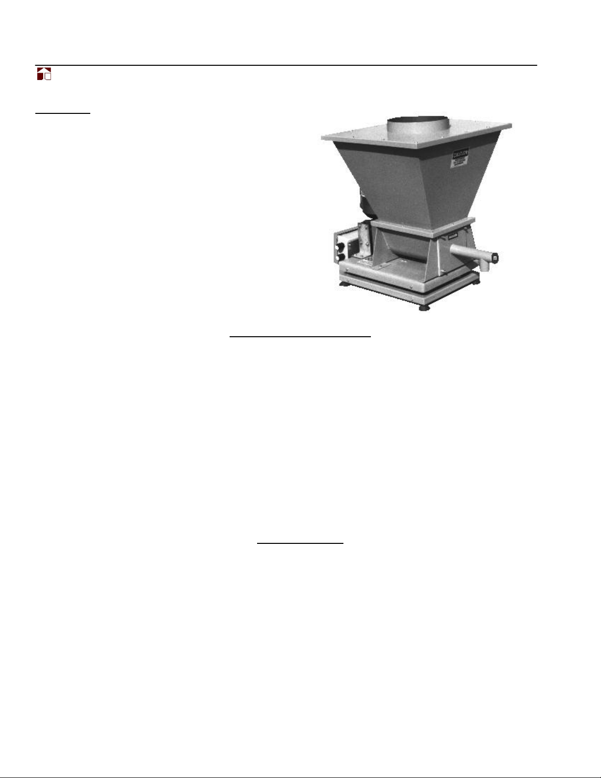
GENERAL DESCRIPTION
When a process requires accuracies greater than 1 to 1 1/2% or it is necessary to record actual feed rates, feeding by
weight loss is the only method. Although material is fed in the same volumetric manner .... the screw flights are filled to
their maximum capacity with uniformly dense material .... required rates are actually monitored by a scaling system in
conjunction with either a batch or continuous controller. Weight of product being delivered is continuously monitored
against weight required.
The "BETTER-WEIGH" feeders are available in a variety of screw sizes and two (2) types of scaling systems. Model BWP
incorporates a platform scale, which consists of our unique screw feeder design with agitator/ conditioner screws, a
platform weigh scale and a controller. With the BWP, the total weight of the feeder and the weight of the product in the
hopper are sensed by the load cell in the platform scale and the combined weight, which will vary based upon the bulk
density of the material, determines the capacity of the load cell to be used.
Our "BETTER-WEIGH" feeder, model BWL, incorporates a lever balance scale system. With this method, the entire
weight of the feeder is counter balanced so that only the contents of the hopper are weighed. This system allows for the
minimal weighment of any product. open top hopper capacities of 2 to 5 cubic feet can be supplied with either model.
INSTALLATION
Even though we have designed our Better-Weigh
®
weigh assemble with stops, you can permanently
damage the load cell if you drop, overload or allow
anything to impact the scale. Care should be taken
to eliminate these occurances.
The gearbox has been filled with oil and shipped with the
vent plug installed. To prevent spills, Keep the feeder
Upright.
The feeder should be located in an area with minimal
traffic or disturbances and mounted on a stable and level
support. After placing the feeder into position, remove
the shipping clips from the upper and lower weighing
deck. The weigh deck’s corner and load cell stops were
adjusted during assembly and should not field adjusted.
Use the wiring schematic supplied with the BetterWeigh® feeder’s NEMA 4 enclosure and make your
connections to the motor and load cell terminals.
If you did not purchase our optional inlet and outlet
sleeves, connect the upstream and downstream
equipment with flexible connections. We recommend a
thin natural rubber or similar type material be used with
enough slack to prevent mechanical sticktion. The more
flexible the connections are, the better the accuracy you
can achieve.
Page 2

Better-Weigh_ Feeders
Installation and Operating Instructions
Metalfab, Inc. Vernon, NJ 07462 Phone (973)764-2000 Fax (973)764-0272 www.metalfab@metalfabinc.com
2
Note: There should be no rigid connections between earth and the Better-Weigh® feeder scale platform.
MAINTENANCE
Our standard Better-Weigh® Feeders are supplied with
metering screws having a standard agitator/conditioner.
Their purpose is to provide a constant supply of
densified product to the metering screw.
Standard machines use a "CinchSeal" rear seal. This is
a Mechanical Seal.
It is made up of an elastomer insert, which is held on the
drive shaft by a spring steel compression ring and
rotates with the shaft while pressing the two rotors
against both end plates.
There should be no product leakage. If there is, remove
the threaded plug on the side of spacer blocks and using
a screwdriver, tighten the compression ring in _ turn
increments.
If the seal is hot to the touch, loosen the compression
ring.
As a rule of thumb, the compression ring should
only be "three fingers tight".
All of the gearboxes are shipped with oil unless
otherwise specified. It's recommend that after the first
500 hours or 4 weeks of operation, and after each
succeeding 2500 hours of operation or every 6 months
thereafter (which ever occurs first) drain the oil, flush out
the case and refill to proper level using the
recommended oil or equivalent.
For normal operating conditions where the surrounding
temperatures are within the limits of 50° F to 120° F, use
AGMA Lubricant #8 COMP, 8EP or similar oil of equal
viscosity and composition. Below 50° F, use an AGMA
Lubricant #7 COMP, 7EP or equal.
The approximate oil capacities of the 2100 gearbox is 18
and the 2400 gearbox is 21 ounces.
As with our other DB1 volumetric feeder models, the
Better-Weigh® feeder is normally supplied with a 1 HP
DC shunt wound (having two fields in series) DC TEFC
motor. When using a SCR DC control having a
230/1/60 VAC input, the motor must be configured for
180 VDC Armature and 200 VDC connections. When
using a SCR DC control having 115 VAC input, the
motor must be configured for 90 VDC Armature and 100
VDC connections.
The motor’s wiring is terminated in a separate NEMA 4
enclosure mounted on the feeder base. When
connecting the motor, follow the schematic supplied in
the enclosure.
The Better-Weigh® feeder’s load cell is sized for each
application. As with the drive, the load cell connections
are terminated in the same NEMA 4 enclosure. Follow
the load cell instructions on the schematic supplied in
the enclosure.
. FEEDER DISASSEMBLY
To remove the screw; first remove the guard, loosen the
packing box’s compression ring and hollow shaft
gearbox’s setscrews. Unbolt the tube from the feeder’s
trough and remove the tube followed by the screw.
The gearbox, packing box, trough, hopper and cover can
be removed by unbolting the individual items.
FEEDER ASSEMBLY
The original packing box and tube gaskets can be
reused. We recommend that the trough and hopper
gaskets be inspected and replaced if required. If the
screw and tube were the only items removed, simply
reverse the disassembly instructions listed above.
If the Better-Weigh Feeder is completely disassembled,
the following applies. The trough, packing box and
gearbox should be loosely bolted in place. Insert the
screw through the trough,
packing box and gearbox. Bolt the tube into place and
tighten the hollow shaft gearbox setscrews.
Line up the gearbox, screw and trough and tighten the
bolts holding the trough to the weigh deck. Turn the
screw by hand and check for interference and alignment.
The gearbox and packing box can be tightened at this
time.
Page 3

Better-Weigh_ Feeders
Installation and Operating Instructions
Metalfab, Inc. Vernon, NJ 07462 Phone (973)764-2000 Fax (973)764-0272 www.metalfab@metalfabinc.com
3
Parts List
A. Sleeve Bearing
B. Agitator/Conditioner Metering Screw
C. Tube
D. Load Cell
E. Inlet Sleeve (Optional)
F. Outlet Sleeve (Optional)
G. Dust Filter (Optional)
5 CU FT
2418
"B"DIM
28 1/2 24 1/2
HOPPER SIZE
3 CU FT
2 CU FT
34
3022 1/224 1/2
3830 1/2 28 1/2
"B"DIM "C"DIM "D"DIM
"C"DIM
"D"DIM
"L"
BWP-1
BWP-1 1/2
BWP-2
BWP-3
1-1/2
2
2-1/2
3-1/2
8 2-3/4
8 2-3/4
"A"
"OD"
8 2-3/4
12 3-1/4
7
3
16
5
1
2
MODEL "OD"DIM "L"DIM "A"DIM
NYLON SLEEVE
END BUSHING
1 HP DC
MOTOR TEFC
LOAD
CELL
6 x 6 NEMA 4
JUNCTION BOX
LEVELERS
HOPPER COVER
(OPTIONAL)
WITH INLET
VENT W/SOCK
10
1
2
C B A
D
G
E
F
Page 4

Better-Weigh_ Feeders
Installation and Operating Instructions
Metalfab, Inc. Vernon, NJ 07462 Phone (973)764-2000 Fax (973)764-0272 www.metalfab@metalfabinc.com
4
ENGINEERING DATA
Load Cells:
A load cell is a strain gage mounted on a machined and calibrated piece of metal. The
metal can be carbon steel, stainless steel or aluminum.
The capacity of a Load Cell is = to Dead Load + Live Load
The Dead Load is equal to the machine’s weight.
The Live Load is equal to the material’s weight.
Weigh Instruments:
The system accuracy is dependent on how well the
weigh instrument can convert the load cell signal to
digital information and how it averages, filters and
tabulates those same digits.
The weigh instrument begins the process by supplying
an excitation voltage (usually 10 volts DC) which excites
the cell. The returning voltage to the instrument is DC,
measured in miliVolts. The value of the signal is
dependent on the strain on the cell (in our case, weight).
The weigh instrument must convert the returned load cell
signal into digital data. During the machine calibration,
we place known weights on the scale and tell the
instrument what the weights values are. Then the
instrument uses those values to calculate a linear line for
signal verses weight values.
Resolution is the number of pieces that the whole load
cell signal is divided by. If we divide the signal by 10, we
then have ten counts of resolution or ten grads or ten
graduations. One thousand divisions would be one
thousand counts of resolution.
The number of resolution is set by the capacity of the
load cell divided by divisions we want to see on the
weigh instrument’s display.
Load Cell Capacity / Display Div. = Resolution
500 pound cell / .01 (Display Div.) = 50,000 counts of resolution
The majority of the weigh instrument manufacturers
advertise up to one million counts of resolution.
All weigh systems are only as good as their load cells.
1:10,000 is used for legal for trade applications, in most
cases 1:30,000 counts of resolution will provide a good
stable reading.
When you divide the signal by the resolution number,
each graduation will have a voltage value. The value of
each graduation can be found by:
Excitation Voltage x miliVolt / Volt x 1000 Resolution
= MicroVolt / Count (grad)
It is important to keep the microVolt / Grad as large as
possible. Or another way of saying it would be:
Use the smallest resolution for the largest graduation
value. All our instruments have digital averaging,
filtering and vibration elimination. When talking about
digital averaging, we need to understand Running
Averaging.
Usually the first step during calibration is to input a digital
average value or use the default settings. After
calibration, the instrument waits until it has counted its
first averages.
If we have the averaging set at 12, the instrument waits
until it has 12 digits and then it calculates its first
average. That digital average is dropped to a register
and waits for digit number 13. Another average is done
and that value is added to the register. The weigh
instrument’s display reflects the digits that were dropped
to the averaging register. An important thing to
remember is that after the instrument waits for the first
12 digits, the register is updated every time another digit
is added.
Page 5

Better-Weigh_ Feeders
Installation and Operating Instructions
Metalfab, Inc. Vernon, NJ 07462 Phone (973)764-2000 Fax (973)764-0272 www.metalfab@metalfabinc.com
5
Both of our instruments use Filtering (vibration
elimination). Think of vibration elimination as “Magic
Numbers”.
In most cases “Magic Numbers” are an asset. But as
with everything else, there is a limit.
We like the fact that the “Magic Numbers” eliminates
repetitive noise, but too much filtering dampens your
readings. When changing the filtering settings, you
sacrifice time. The higher the setting, the longer it takes
to make that filtering calculation.
MEASURING ACCURACY:
When testing one of our Better-Weigh® Feeders, we
catch 30 consecutive one minute samples.
The plus & minus deviation of these samples are
analyzed using 2 Sigma deviation formulas.
When sampling, 65% of the samples will fall within one
standard deviation or (1) Sigma and 95% will fall within
two standard deviations or (2) Sigma. The loss-in-weight
industry has standardized on the 2 Sigma as an
accuracy statement.
CONTROL FEATURES - "BETTER-WEIGH"® BATCH LOSS-OF-WEIGHT FEEDER
With the "BETTER-WEIGH" batch feeder model BWP,
accuracies of =/- 0.5% can be achieved with 2 lb.
batches and +/- 0.25% accuracy with 5 lb. or greater
batches with time spans of 30 to 90 seconds. The BWL
model can easily produce an accuracy of +/- 0. 5% in 1
lb. batches.
The METALFAB batch controller is used to control the
fast (bulk) and slow (dribble) speeds of our
"BETTER-WEIGH"@ feeders.
1. The bulk dribble targets are entered through the
front panel or down loaded to the indicator using
RS-232 or optional RS-485 and Allen Bradley
Blue Hose communications. The feeders fast
and slow speeds are set manually and are
initiated by the weigh indicator's twenty (20)
programmable steps.
2. In addition to the fast and slow speed outputs,
the indicator has two (2) additional outputs
which can be configured for a refill, batch
complete or general alarm conditions.
3. Formatting printing can be done and is activated
by one of the programmable steps or by
pushing the print button located on the front
panel.
4. The indicator is also supplied with four
accumulators and their values printed through
the print functions.
5. Vibration elimination is used to remove motor
and machine noise from the raw digital data
used for weigh indication. It is also an added
benefit when using vibration to assist with
feeding.
6. Both the SCR DC drive and weigh indicator are
mounted in the same NEMA 4 enclosure having
a power on/off switch with light, Jog/Batch and
Abort/Start selector switches.
7. Normally the control is supplied 230/1/60 VAC
As an option, 115/1/60 VAC can be supplied.
For a detailed description of the Batch Control and
installation, calibration and operating instructions,
refer to the schematics and instructions enclosed in
our control enclosure.
Page 6

Better-Weigh_ Feeders
Installation and Operating Instructions
Metalfab, Inc. Vernon, NJ 07462 Phone (973)764-2000 Fax (973)764-0272 www.metalfab@metalfabinc.com
6
CONTROL FEATURES - "BETTER-WEIGH" CONTINUOUS LOSS-OF-WEIGHT FEEDER
Unlike the batch loss-of-weight feeders, the continuous
weighers deliver an ongoing flow of material. The
loss-of-weight of material per time is constantly
monitored in order to maintain a continuous
loss-of-weight with an accuracy of ± 0.25% to 0.5% with
(1) minute samples.
The METALFAB continuous controller is used to control
the speed of our "BETTER-WEIGH" feeders based on
the amount of material weight loss within a time period.
1. The rate targets are entered through the front
panel or can be down loaded to the indicator
using RS-232, optional RS-485 or Allen Bradley
Blue Hose communications.
2. After our "BETTER-WEIGH" continuous
controller has been installed, load cell and
automatic rate calibrations are performed. The
Proportion, Integral and Derivative factors are
automatically calculated and stored in the
indicator. This eliminates the trial and error
methods used by other manufacturers.
3. Operation of the control can be manual,
continuous or continuous batching. In all modes
of operation, the indicator monitors material
gross weight and initiates automatic refills with
high and low level alarms.
4. The feed rate can be set for lbs./sec., lbs./min.
or lbs./hr. A rate tolerance input is used to
provide a band for monitoring the indicator's
performance. If the rate is operating out of
tolerance for a set time, the indicator will output
an alarm and can be programmed to
automatically shut down the feeder.
5. The indicator uses vibration elimination to
remove noise from the raw digital data used for
weigh indication. The sensitivity can be preset to
eliminate noise from machines, motors or
vibrators.
6. As with our batch feeder control, both the SCR
DC drive and weigh indicator are mounted in the
same NEMA 4 enclosure having a power on/off
switch with light and indicator keypad and
display.
7. The control is supplied as 230/1/60 VAC. As an
option, 115/1/60 VAC can be supplied.
For a detailed description of the Continuous Control
and installation, calibration and operating
instructions, refer to the schematics and
instructions enclosed in our control enclosure.
Metalfab has designed our
Better-Weigh® machines to have:
The minimal “Dead Load”
The maximum “Live Load”
To use the smallest load cell capacity
With the biggest Resolution
 Loading...