

Metal Fab 4CGSWHVK, 4CGVSWHVK Installation Manual
CORR/GUARD ADDENDUM
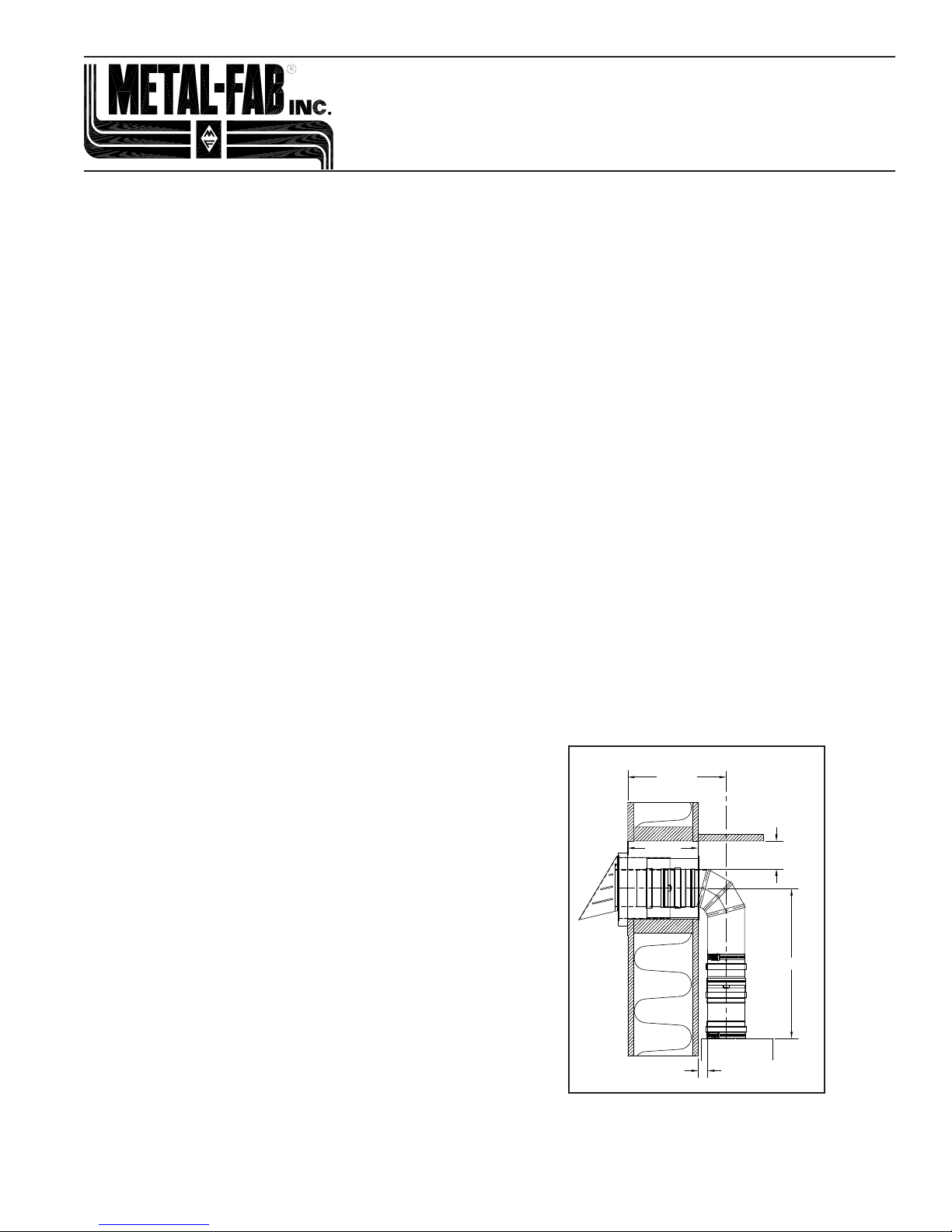
3.00"
MIN.
1.00"
MIN.
APPLIANCE
WALL
ROOF
12.5"-16.0"
4.5"-9.0"
8.5"-12.0"
4CGSWHVK & 4CGVSWHVK
INSTALLATION INSTRUCTIONS
IMPORTANT: DO NOT INSTALL WITHOUT FIRST READING
THESE INSTRUCTIONS VERY CAREFULLY.
These instructions pertain to the installation of the 4CGSWHVK
& 4CGVSWHVK vent kits.
The Corr/Guard 4CGSWHVK & 4CGVSWHVK vent kits are
designed for sidewall venting of instantaneous tankless water
heaters and wall hung boilers. Each kit contains the parts
necessary to vent through any combustible wall. The vent kit is
compatible with standard Corr/Guard products.
Be sure to read these instructions completely, and those of the
appliance itself, before proceeding with the installation of this
kit. Additional information and requirements regarding the use
and installation of Corr/Guard products can be found in the
installation instructions (L2153 and L2154). Installation is to be in
accordance with local and national building codes.
The UL Listing for this product is void if components other than
those supplied as Listed Components by Metal-Fab, Inc. are
used. All warranties, stated or implied, are void if this product
and the appliance to which it is connected are not installed in
accordance with their respective instructions and jurisdictional
code requirements.
Proper joint assembly is essential for a safe installation. Failure
to follow these instructions and sound installation practices can
lead to risk of damage, re and carbon monoxide poisoning.
KIT COMPONENTS:
The following items are included in the box for this kit:
• Wall thimble termination.
• 2 each male adjustable collars.
• Telescoping 90-degree elbow.
• Appliance adapter.
• Installation instructions.
GENERAL REQUIREMENTS:
WARNING: Failure to conform to any of these requirements. May
violate local, state, or national codes and create conditions that
may cause catastrophic property damage or personal injury.
• Proper operation of the vent system and appliance depends
on the use and correct assembly of all parts specied by
Metal-Fab, Inc. for a particular installation.
• If required by the appliance manufacturer, a drain tting
must be located as close as possible to the appliance ue
outlet.
• More than one appliance may not be connected to the same
• Vent system must avoid any contact with plumbing or
• Proper clearances to combustibles must be maintained over
vent kit termination.
electrical systems.
the entire length of the system (FIG. 1). Maximum appliance
outlet temperature must not exceed 480 degrees Fahrenheit
and a rating for positive pressure of 10” W.C..
• Refer to the appliances instructions to determine limitations
with respect to the installation and use such as maximum
horizontal length from the appliance, maximum height,
joining of two or more parts to constitute the intended
assembly, maximum number of joints or sections of pipe for
use in the assembly, and required installation clearances.
• Do not place any type of insulation in the required clearance
spaces surrounding the vent system.
• Never install Corr/Guard on an appliance that is not listed for
use with a Special Gas Vent or Type BH Vent.
• Additional Corr/Guard vent lengths can be installed
for extended runs. The overall equivalent length of the
system shall not exceed the specications of the appliance
manufacturer’s instructions.
• Horizontal vent runs shall have a slope of no less than 1/4
inch (6.4mm) every 12 inches (305mm) to prevent collection
of condensate.
• The termination should be away from trees, shrubs, or
decorative items as ue gases could cause damage.
• The venting system must be free to expand and contract.
• Check for unrestricted vent movement through walls,
ceilings, and roof penetrations.
• Manufacturers have different joint systems and adhesives.
Do not mix pipe, ttings, or joining methods from different
manufacturers.
FIG. 1
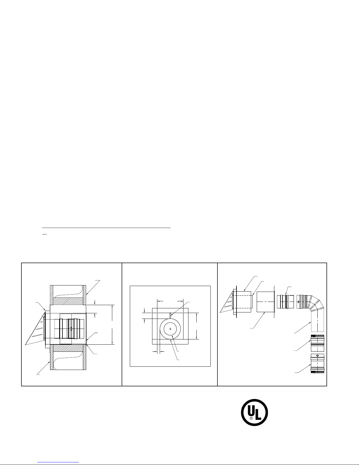
GENERAL TERMINATION GUIDELINES:
THIMBLE
HOOD
INNER
THIMBLE
0" BOTTOM
CLEARANCE
1.75" TOP
CLEARANCE
WALL
OUTSIDE SURFACE
INSIDE SURFACE
8.25"
SQUARE
8.250
OPENING
8.250
OPENING
1.750
0.875
HOOD REMOVED FOR CLARITY
6.50" DIA. THIMBLE
0" CLEARANCE
VENT
4.00" DIA.
SPACER
CLIP
HOOD THIMBLE
INNER THIMBLE
SLIP COLLAR
ELBOW
ADJUSTABLE COLLAR
APPLIANCE ADAPTER
VENT SLEEVE
NOTICE: The following is to be used as a guideline only. Check
with the code enforcement ofce in your area for specic
termination requirements.
A mechanical draft vent system, excluding direct-vent appliances,
shall terminate at least 4 feet (1219 mm) below, 4 feet (1219
mm) horizontally from, or 12 inches (305 mm) above any door,
window, or gravity air inlet into any building. The bottom of the
vent terminal shall be located at least 12 inches (305 mm)
above grade. In geographical areas where snow accumulates,
terminate the system at least 12 inches (305 mm) above the
snow line. The termination must be kept clear of snow and ice
at all times.
NOTE: The State of Massachusetts requires additional
restrictions for vent terminations located less than 7 feet
above grade. Consult your local code.
The termination of the venting system shall not be located in
trafc areas, such as walkways, unless the venting system is at
least 7 feet (2.13m) above the ground.
INSTALLATION INSTRUCTIONS:
• Examine all components for possible shipping damage prior
to installation.
• Do not penetrate or puncture any part of the system with
fasteners.
• Determine the location and cut a 8.25” x 8.25” (210mm x
210mm) opening for the wall thimble (FIG. 2).
o Position thimble hood into the opening so that the
angled hood is located on the outside of the structure.
The thimble hood is not centered in the opening (FIG.
3). Clearance to combustibles at top of thimble is
1.75” (44 mm), bottom of thimble is 0” (0 mm), and
centered from side to side. The clip attached to the
top of the thimble will maintain the necessary clearance
to combustibles.
o Apply a bead of silicone between the structure and
mounting plate before nailing or screwing thimble hood
to the outside surface of the building.
o From the inside, slide the inner thimble sleeve into the
thimble hood sleeve until the surface is ush to the wall.
Fasten with screws or nails.
• Slide the adjustable collar over the thimble hood vent sleeve.
Insert female end of 90° elbow onto adjustable collar until it
locks. Slide adjustable collar onto male end of 90° elbow.
Insert female end of appliance adapter onto adjustable
collar until it locks. Attach appliance adapter to appliance
collar.
• Adjust collars until the desired pitch is achieved.
• Tighten clamps at the adjustable collar and appliance
adapter until snug.
• When installing the adjustable collars, it is important to make
sure that each end is inserted past the silicone gasket. To
ensure the collars are fully engaged, at least two inches of
sleeve must be inserted.
• If you are unable to insert the sleeves at least two inches
into the adjustable collars, additional vent lengths must be
installed.
• Prior to initial start up, check the entire system to ensure
all joints are secured and sealed correctly. The seams and
joints must be checked for gas tightness when using the
venting system with Category III or IV appliances and for
free movement of the outlet ap. Metal-Fab recommends
that a qualied inspector check the entire system at least
once annually following the initial installation.
• The installation must conform to the requirements of the
appliance manufacturer’s instructions, the National Fuel
Gas Code, and local codes and regulations.
FIG. 2
FIG. 3
FIG. 4
C US
LISTED
©2010 Metal-Fab, Inc. Form No. L2376 - 04/10
8624
 Loading...