


TM
User Guide
for Windows® and Macintosh
®

Trademarks
Credits
MetaCreations and the MetaCreations logo are
registered trademarks of MetaCreations
Corporation. Canoma is a trademark of
MetaCreations Corporation.
“Macintosh” is a registered trademark of Apple
Computer, Incorporated. “Windows” is a
registered trademarks of Microsoft
Corporation. “Pentium” is a registered
trademark and “i486” is a trademark of Intel
Corporation. All other product names
mentioned in the manual and other
documentation are used for identification
purposes only and may be trademarks or
registered trademarks of their respective
companies. Registered and unregistered
trademarks used herein are the exclusive
property of their respective owners.
MetaCreations Corp. makes no claim to any
such marks, nor willingly or knowingly misused
or misapplied such marks.
Copyright
This manual, as well as the software described
in it is furnished under license and may only be
used or copied in accordance with the terms of
such license. Program ©1999 MetaCreations
Corporation, including the look and feel of the
product. MetaCreations Canoma User Guide
©1999 MetaCreations Corporation. No part of
this guide may be reproduced in any form or by
any means without the prior written permission
of MetaCreations Corporation.
Canoma was Engineered by Tilman Reinhardt,
Robert Seidl, Luc Heinrich, and Gerald
Guyomard, with support from Arnoud Berry,
Brian Wagner, Seath Ahrens, and Alexei
Lebedev. Installer by Carin Lew.
User Interface Design by Robert Bailey.
Product Management by Robert Seidl.
Quality Assurance Testing management by
Michael Cinque. Quality Assurance Testing by
Brian Romero, Joe Grover, Steve Rathmann,
John Taylor, Eric Gruye, and Dan Huver.
The Canoma User Guide was written by Linda
Stevens, assisted by Robert Seidl and Tilman
Reinhardt; project managment by Linda
Stevens and Erick Vera; layout design by
Tish Loosley
Art Directed by Brian Moose; manual
illustration by Aaron Begley, Quick Reference
Card design and layout by Jeffry Schwartley;
Box Design by Nathan Harris.
Thanks to John Leddy and Pierre Berkaloff for
their support.
Some images provided by Photodisc.
Notice
Before using this software or reading this user
guide, make sure you have read, understood
and agreed to the license contained in the back
of the Canoma User Guide.

Contents
Welcome to Canoma
Application Overview
Tutorial
What is Canoma?. . . . . . . . . . . . . . . . . . . . . .14
When You Have Questions. . . . . . . . . . . . . .18
Technical Support. . . . . . . . . . . . . . . . . . . . .19
Installing Canoma. . . . . . . . . . . . . . . . . . . . .20
The Canoma Workspace. . . . . . . . . . . . . . . .24
Status Tips. . . . . . . . . . . . . . . . . . . . . . . . . . .28
About Canoma. . . . . . . . . . . . . . . . . . . . . . . .28
Accessing the MetaCreations Web Site. . . .28
Welcome . . . . . . . . . . . . . . . . . . . . . . . . . . . .30
Creating a 3D Model . . . . . . . . . . . . . . . . . .30
Lesson1: Pinning Corners . . . . . . . . . . . . . . . . . .30
Lesson 2: Viewing Progress . . . . . . . . . . . . . . . . .33
Lesson 3: Adding Textures and a
Ground Plane . . . . . . . . . . . . . . . . . . . . . . . . . .34
Filling in the Details . . . . . . . . . . . . . . . . . .35
Lesson 1: Adding a Second Image . . . . . . . . . . .35
Lesson 2: Modeling Nearby Objects . . . . . . . . . .38
Lesson 3: Adding a Close-up Image . . . . . . . . . .40

Canoma
Basics
Lesson 4: Editing Textures . . . . . . . . . . . . . . . . .41
Creating a Building Model . . . . . . . . . . . . .42
Lesson 1: Starting with One Object . . . . . . . . . .42
Lesson 2: Completing the Job . . . . . . . . . . . . . . .44
Reducing Confusion . . . . . . . . . . . . . . . . . . . . . .45
Lesson 3: Navigating Through a Model . . . . . . . .45
Aligning Objects Precisely . . . . . . . . . . . . .46
Lesson 1: Using Glue . . . . . . . . . . . . . . . . . . . . . .46
Picking Up Speed . . . . . . . . . . . . . . . . . . . . .50
Lesson 1: Duplicating Similar Elements . . . . . . .50
Lesson 2: Adding Detail . . . . . . . . . . . . . . . . . . . .52
Lesson 3: Adding a Ground Plane . . . . . . . . . . . .53
Introduction . . . . . . . . . . . . . . . . . . . . . . . . .56
Table of Contents
Customizing Canoma . . . . . . . . . . . . . . . . . .56
Setting Canoma Preferences . . . . . . . . . . . . . . . .56
Saving Workspace Customizations . . . . . . . . . . .56
Using the Active Guide . . . . . . . . . . . . . . . . . . . .57
Choosing a 2D Image Editing Application and
Image Format . . . . . . . . . . . . . . . . . . . . . . . . . .57
Setting Up Your Workspace . . . . . . . . . . . .57
Working in the Project Window . . . . . . . . . . . . .57
Using the Camera Controls . . . . . . . . . . . . . . . . .58
Understanding the Toolbar . . . . . . . . . . . . . . . . .58
iv

Changing Canoma Colors . . . . . . . . . . . . . . . . . .58
Creating a Canoma Project . . . . . . . . . . . . .60
Organizing the Project Folder . . . . . . . . . . . . . . .60
Using 2D Images . . . . . . . . . . . . . . . . . . . . .60
Creating 3D Models . . . . . . . . . . . . . . . . . . .60
Adding Texture . . . . . . . . . . . . . . . . . . . . . .61
Creating Animations . . . . . . . . . . . . . . . . . .61
Undoing Operations . . . . . . . . . . . . . . . . . .61
Saving and Closing . . . . . . . . . . . . . . . . . . .62
Saving the Project . . . . . . . . . . . . . . . . . . . . . . . .62
Closing Canoma . . . . . . . . . . . . . . . . . . . . . . . . . .62
Importing, Exporting, and Rendering . . . .62
Importing . . . . . . . . . . . . . . . . . . . . . . . . . . . . . . .62
Exporting . . . . . . . . . . . . . . . . . . . . . . . . . . . . . . .63
Rendering 2D Images . . . . . . . . . . . . . . . . . . . . .64
Rendering Animations . . . . . . . . . . . . . . . . . . . . .65
Preparing Projects
Taking Photographs . . . . . . . . . . . . . . . . . .68
What Works Best . . . . . . . . . . . . . . . . . . . . . . . . .68
Using Several Photographs . . . . . . . . . . . . . . . . .68
Working from Overviews to Detailed Photos . . .69
Don’t Move Things . . . . . . . . . . . . . . . . . . . . . . . .69
One Photo, One Image File . . . . . . . . . . . . . . . . .69
Modifying Photos . . . . . . . . . . . . . . . . . . . . . . . . .69
v
Canoma

Building Projects
Controlling Exposure and Lighting . . . . . . . . . . .70
Handling Camera Location . . . . . . . . . . . . . . . . .70
How Canoma Works . . . . . . . . . . . . . . . . . .74
Modeling 3D Objects . . . . . . . . . . . . . . . . . . . . . .74
Using 2D Source Images . . . . . . . . . . . . . . . . . . .74
Modeling from the Ground Up . . . . . . . . . . . . . .74
Always Calculating . . . . . . . . . . . . . . . . . . . . . . . .74
Before You Start . . . . . . . . . . . . . . . . . . . . .75
Using the Canoma Workspace . . . . . . . . . .75
The Project Window . . . . . . . . . . . . . . . . . . . . . .75
Camera Controls . . . . . . . . . . . . . . . . . . . . . . . . .76
2D Image Palette . . . . . . . . . . . . . . . . . . . . . . . . .76
Selecting Colors . . . . . . . . . . . . . . . . . . . . . . . . . .76
Working with Canoma Projects . . . . . . . . .76
Table of Contents
Working with Objects . . . . . . . . . . . . . . . . .77
Matching Objects to Photo Elements . . . . . . . . .77
Selecting the Correct Object . . . . . . . . . . . . . . . .77
Objects with Editable Polyline Contours. . . . . . .85
Calibrating a Scene . . . . . . . . . . . . . . . . . . . . . . .88
Adding an Object . . . . . . . . . . . . . . . . . . . . .88
Setting Selection Based Options . . . . . . . . . . . . .88
Selecting an Object . . . . . . . . . . . . . . . . . . .89
Deleting an Object . . . . . . . . . . . . . . . . . . . .89
vi

Checking Object Information . . . . . . . . . . .89
Stacking Objects . . . . . . . . . . . . . . . . . . . . .90
Duplicating Objects . . . . . . . . . . . . . . . . . . .91
Pinning Objects . . . . . . . . . . . . . . . . . . . . . .92
Viewing Projects in Progress . . . . . . . . . . . .93
Using Beads . . . . . . . . . . . . . . . . . . . . . . . . .93
Defining Edges . . . . . . . . . . . . . . . . . . . . . . . . . . .93
Using Glue . . . . . . . . . . . . . . . . . . . . . . . . . .94
Gluing Objects Together . . . . . . . . . . . . . . . . . . .94
Deleting All Constraints . . . . . . . . . . . . . . .94
Using Solo Mode . . . . . . . . . . . . . . . . . . . . .95
Using Shadows . . . . . . . . . . . . . . . . . . . . . . .95
Displaying the Background Image . . . . . . .96
Avoiding Model Stress . . . . . . . . . . . . . . . . .96
Working with Texture . . . . . . . . . . . . . . . . .97
Adding Textures . . . . . . . . . . . . . . . . . . . . . . . . . .97
Stealing Textures . . . . . . . . . . . . . . . . . . . . . . . . .97
Adding More Detail . . . . . . . . . . . . . . . . . . .98
Using the 2D Image Palette . . . . . . . . . . . . . . . . .99
vii
Canoma

Viewing
Models
Editing
Textures
Positioning the View of Your Model . . . . .102
Using Canoma Camera Controls . . . . . . . .102
Using the Trackball . . . . . . . . . . . . . . . . . . . . . .102
Using the Cross Controls . . . . . . . . . . . . . . . . . .103
Using the In-View Navigation Controls . . . . . . .104
Banking Control . . . . . . . . . . . . . . . . . . . . . . . . .104
Field of View . . . . . . . . . . . . . . . . . . . . . . . . . . .105
Zooming and Panning . . . . . . . . . . . . . . . .105
Zooming . . . . . . . . . . . . . . . . . . . . . . . . . . . . . . .105
Panning . . . . . . . . . . . . . . . . . . . . . . . . . . . . . . .106
Resetting the Viewpoint . . . . . . . . . . . . . .106
Creating
Animations
Table of Contents
Retouching or Editing Textures in 2D . . .110
Editing for 2D Renders . . . . . . . . . . . . . . . . . . .111
Using the Alpha Channel . . . . . . . . . . . . .112
How Animation Works in Canoma . . . . . .116
Creating an Animation . . . . . . . . . . . . . . .116
Using the Animation Controls . . . . . . . . . . . . . .116
Creating Keyframes . . . . . . . . . . . . . . . . . . . . . .116
viii

Advanced
Modeling
Setting Animation Options . . . . . . . . . . . . . . . .117
Previewing an Animation . . . . . . . . . . . . .117
Rendering an Animation . . . . . . . . . . . . . .118
Modeling Objects . . . . . . . . . . . . . . . . . . . .120
Adding Source Images . . . . . . . . . . . . . . . . . . . .120
Free vs. Constrained Parameters . . . . . . . . . . . .121
Misleading Canoma and Stressing a Model . . . .121
Listening to the Canoma “Heartbeat” . . . . . . . .122
Using Geometric Tricks . . . . . . . . . . . . . . . . . . .122
Establishing Perspective . . . . . . . . . . . . . .123
Starting Simple . . . . . . . . . . . . . . . . . . . . . . . . .123
Modeling the First Image . . . . . . . . . . . . . . . . . .123
Using Temporary “Helper” Objects . . . . . . . . . .124
Creating the Same Orientation . . . . . . . . .124
Duplicating Objects . . . . . . . . . . . . . . . . . .125
Freeing Necessary Parameters . . . . . . . . .126
Monitoring Stress in the Model . . . . . . . .126
Using Glue to Align Objects . . . . . . . . . . .127
Using Point To Point Glue . . . . . . . . . . . . . . . . .128
Don’t "overglue" . . . . . . . . . . . . . . . . . . . . . . . .128
Using Point to Edge Glue . . . . . . . . . . . . . . . . .130
Creating a Balcony . . . . . . . . . . . . . . . . . . . . . . .132
ix
Canoma

Table of Contents
x
1
Welcome to
Canoma
What’s in this Chapter:
What is Canoma?. . . . . . . . . . . . . . . . . . . .14
What Can You Do with Canoma? . . . . . . .15
When You Have Questions . . . . . . . . . . . .18
About your User Guide . . . . . . . . . . . . . . .18
Technical Support . . . . . . . . . . . . . . . . . . .19
Installing Canoma . . . . . . . . . . . . . . . . . . .20
What is Canoma?
Canoma lets you quickly create photorealistic
3D models from scanned or digital
photographs, without extensive 3D modeling
skills. No need for specialized equipment or
calibrations. Canoma even works on historical
photographs. Canoma models can be posted on
Web sites or in electronic catalogs, or imported
into traditional 3D modeling and animation
software. Canoma is a perfect companion to
other Web authoring tools.
Easier to learn than traditional 3D programs
(with all their modes, tools, and windows),
Canoma lets 2D graphic illustrators and
designers create and manipulate realistic 3D
models—applying all their retouching and
filtering skills to 3D objects.
Here’s how Canoma works:
• Take one or more photos of what you want
to model in 3D. More photos mean greater
detail.
• Select 3D shapes (called objects or
pimitives,) then pin them to the corners of
objects in your photograph. (There are
ways to also control edges and alignment.)
• Preview your 3D creation—move in for a
close-up look or away, rotate around the
model, or just walk through it! Canoma
adds texture to your model right from your
photographs.
• You can edit areas of texture, letting
Canoma open your favorite 2D program,
present you with a head on 2D view of the
area to edit, then watch as Canoma
reapplies the edited texture in proper
perspective!
• Create animations or export your 3D
model to other 3D programs or for use on
the W eb.
Welcome to Canoma
The Canoma workspace.
14
What Can You Do with
On-line Catalogs
Canoma?
With Canoma you can create very realistic
three-dimensional (3D) computer models from
one or more photographs, a process called
image-assisted modeling. Canoma models have
simple geometries and use photographs as
texture source, allowing the pixels to do the
work of making your models look good.
Select the face of a Canoma model, bring up a
2D pixel editing tool, such as Painter or
Photoshop, and retouch the surface texture,
add text, or apply a 2D filter. Watch Canoma
reapply the altered pixels, while retaining 3D
perspective.
3D models can be rotated and viewed from
different directions, allowing customers to
thoroughly inspect product or merchandise
models. Once 3D models are completed, you
can create a simple animation or “walk
through”, even publish those on the internet.
Canoma lends itself well to regular, man-made
objects. Amorphous or very complex shapes
that may occur in nature such as trees,
mountains, or curved objects can also be
approximated, using simple stand-in geometry.
Canoma also supports translation sweeps or
extrusion, whic h allows a polyline contour to be
swept along a straight axis.
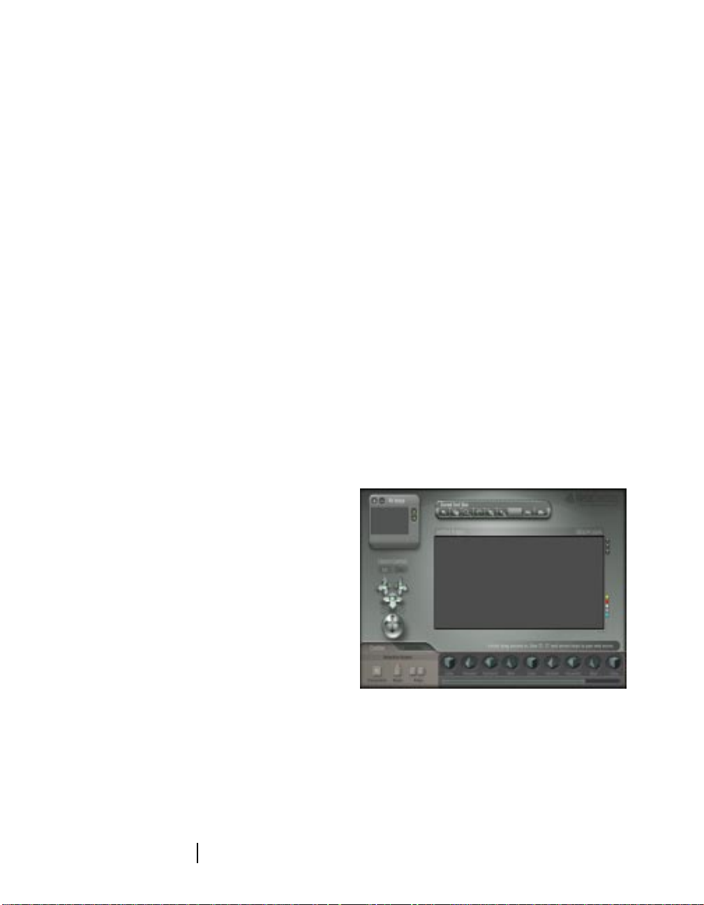
You can publish a Web catalog full of Canoma
models. For example, you could use Canoma to
create a catalog of “hard goods”, such as
furniture or appliances, then output it in the
Metastream format.
Examples of models created for catalogs.
15
Canoma

The Metastream format is widely distributed by
Microsoft and Intel and can be downloaded for
free from www.metastream.com. Metastream
uses small, compact files and outputs a single
file that is easy to maintain and post.
Streaming a 3D image allows customers to
experience instant gratification, as they
manipulate a 3D object. High quality,
interactive vending, all from within a standard
Web browser.
Interior/Exterior Design and
Remodeling
If the project is to remodel a kitchen, bathroom
or the outside of a house, a photograph session
and a quick modeling session—without
becoming a wizard—creates a model of how the
project looks right now. Repeat site visits are
replaced by a photorealistic 3D model, that’s
always available for a design meeting.
Canoma creates quick, low-polygon count,
photorealistic models. This can be a fast, costeffective way of disseminating information,
without the security risk that distributing
detailed blueprints from a CAD program could
introduce.
Web Sites, Travel and Tourism,
Commercial Real Estate
A 3D preview of property can be a strong sales
incentive for online travel, real estate sales, or
vacation rentals. Entertainment, restaurant,
and hotel information sites all benefit from the
photorealistic 3D models.
• Using the texture editing feature, you and
your 2D pixel editing tool, such as Painter
or Photoshop, can make changes to
surfaces or simulate different lighting.
• With Canoma’s animation feature, y ou can
“walk” perspective clients through the
suggested changes.
A Canoma model created from a photo of San Francisco.
The "For Rent" sign was added using a 2D pixel editing
program.
Welcome to Canoma
Walking through a kitchen model.
16
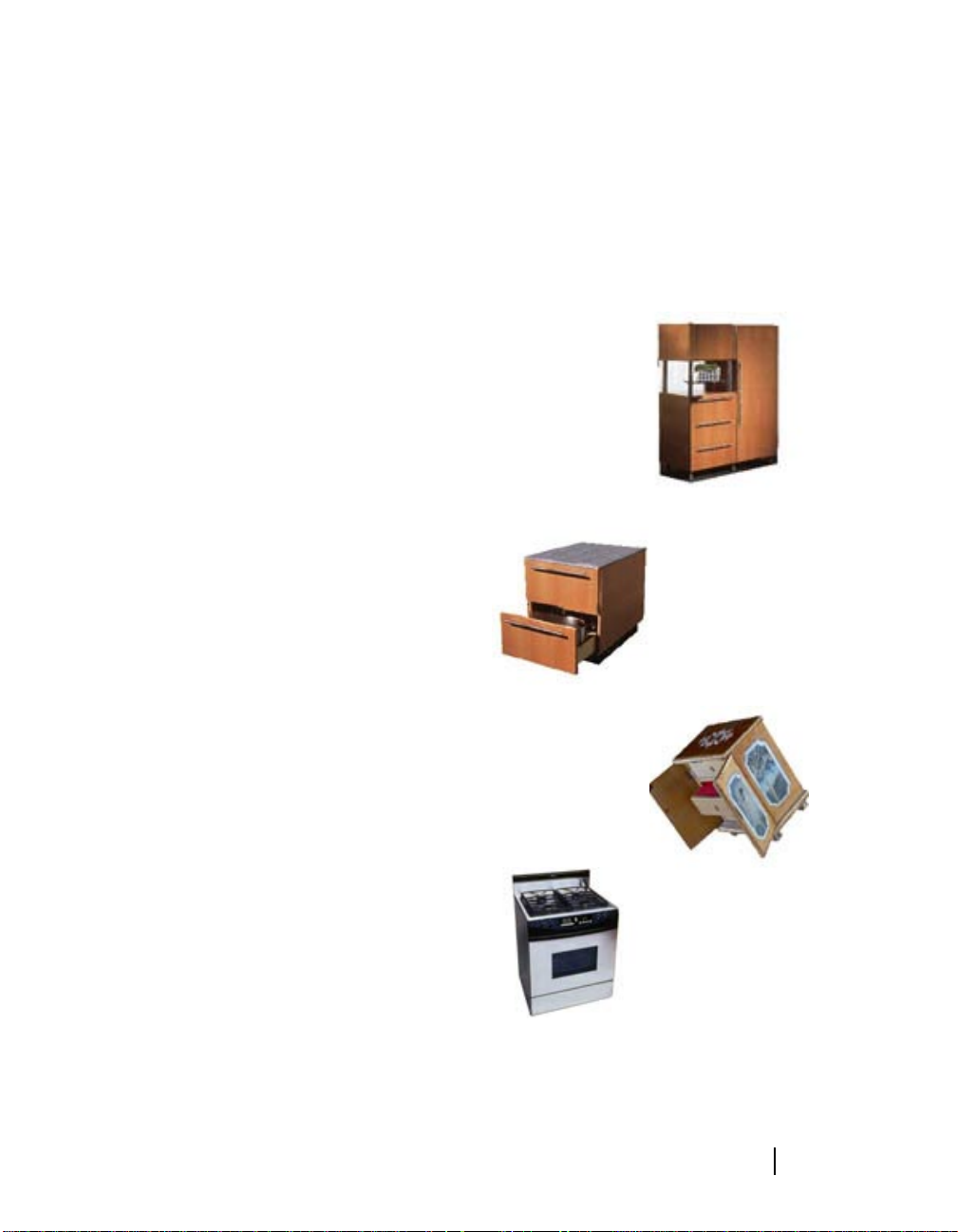
• With a 3D program you can go further,
changing tiles, sliding in a ne w dishwasher,
or actually trying out planned spotlights to
illuminate that kitchen counter.
Before
It’s easy to add billboards, place advertising on
buses, and change details—all in photorealistic
perspective, using only Canoma and your
favorite 2D image editing program. You can
output the results as 3D models, rendered 2D
images, or even animations.
After
Spotlights added to a Canoma model in a 3D program.
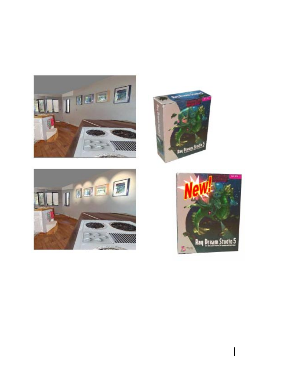
Graphic Design and Advertising
Industrial design and graphic artists can take
existing products and packaging, extract the
graphics, and edit the designs. They can create
animations or place a package in a different
environment.
You can edit Canoma models with an image-editor.
Architecture, Urban Planning,
Property Development
Architects can produce rough models of areas
where new buildings are planned, then
integrate the photorealistic model produced in
Canoma with the detailed engineering model of
17
Canoma
the planned building, giving everyone a good
preview of how a building might fit into the
neighborhood.
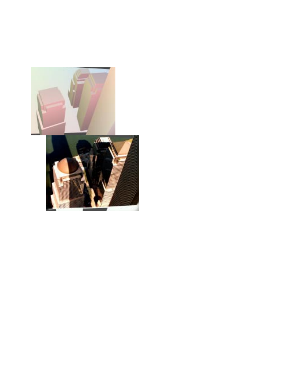
A Canoma model generated from a photo of the New Y ork
skyline can let you see how a new building might look in
the cityscape.
Computer Game Dev elopers and
3D Artists
With Canoma, you can quickly model a house
or office, change some textures, add in a few
monsters, and really try out ideas . 3D artists can
use Canoma to create quick photorealistic clip
objects that can be used to enhance existing 3D
models and animations.
Canoma models of complete houses or
interiors can serve as starting points for more
detailed 3D modeling, since the y pro vide scene
measurements and object dimensions.
When Y ou Have
Questions
You can find answers to most of your questions
in the following ways:
• Canoma User Guide - Providing all the
information you need to get the most out
of Canoma. The User Guide is also
provided as a PDF file on the Canoma CD.
• Online Help - Providing direct access to
specific chapters in the User Guide. Online
Help contains the same information as the
User Guide. Adobe Acrobat Reader
software is required to read online Help or
the PDF version of the User Guide. Adobe
Acrobat Reader software is on the Canoma
CD or downloadable for free from
www.adobe.com.
• Status line tips - Check the bottom of your
screen for UI related information.
• Active Guide - Text can pace you through
the creation and application of your first
few primitives. The Active Guide goes away
after you’ve gained some experience or y ou
can turn it off in the program preferences.
About your User Guide
The Canoma User Guide is for both Macintosh
and Windows. By convention, Macintosh
commands precede W indows commands in the
text. For example, Command/Ctrl+I, is
equivalent to the Macintosh Command-I and
the Windows Ctrl+I. For simplicity, the term
“folder” refers to directories as well as folders.
The Canoma interface for Macintosh and
Windows platforms is identical, unless
otherwise specified.
Welcome to Canoma
18

When a modifier key differs between the
Macintosh and Windows platform, the
Macintosh modifier is listed first followed by a
slash and the Windows modifier key. Option/
Alt means Macintosh users press the Option
key and Windows users press Alt.
There are several conventions used to identify
paths to certain tools and controls. The
convention to a menu follows the rule of the
menu name > menu item
palette follows the rule of the
subpalette name
menu follows the rule of
menu> menu item
. The convention to a palette
. The convention to a
palette name:
palette name: palette
.
Technical Support
MetaSupport is a portfolio of free and feebased support options designed to provide
quality support to you.
The options are as follows:
FREE On-line Support
On-line support is available on our Web site at
www .metacreations .com 24 hours a day, 7 days a
week. Access a list of Frequently Asked
Questions (FAQs) for each product and find
solutions immediately. If, after searching our
on-line options, you still need assistance, you
can contact MetaCreations Technical Support
through one of the Telephone Support Services
listed here.
Telephone Support
support duration. The length of the
complimentary support period depends on
whether your MetaCreations product is a
Level I (receive 90 days of complimentary
support for a first-time purchase, or 30
days for an upgrade) or Level II (receive
complimentary support for one incident
for a first-time or upgrade purchase)
product. The support period begins with
your first call into MetaCreations Technical
Support, provided you have registered the
product.
Toll call:
• Premium Pay as You Go
When your standard support period ends,
you can now receive priority access
personal service regarding installation,
configuration and general usage questions
from our qualified support specialists. You
pay a flat fee that covers all of the necessary
support for the particular incident.
Toll-free call:
• Premium Plus Annual Contract
Annual support contracts are available to
meet your ongoing support needs. Sign up
for an annual support agreement to receive
one year of toll-free priority access personto-person assistance. Get answers to
installation, configuration and general
usage questions.
• To order toll-free call:
• For support toll-free call:
831-430-4200
888-456-6382
800-846-0111
800-683-5872
• Standard Support
Talk person to person with technical
support representatives and get answers to
installation, configuration and general
usage questions. Each product has its own
For a list of
Level II products
options pricing
www.metacreations.com.
currently supported Level I and
19
and the
, please visit our web-site at
Telephone Support
Canoma

Technicians are available
Friday, 6am to 5pm Pacific Time
Monday through
.
How to Contact Us
• Free On-line Support:
www.metacreations.com
• Standard Support: Toll call 831-430-4200
• Premium Pay As You Go: Toll-free call
888-456-6382
• Premium Plus Annual Contract:
• To order toll-free call: 800-846-0111
• For support toll-free call: 800-683-5872
System Requirements
(Windows)
• Pentium processor
• Windows 95, Windows 98, Windows NT
• 32 mb free RAM (48+ mb recommended)
• 50 mb of hard-disk space
• 16 bit color (24 bit recommended)
• CD Rom drive (for install)
System Requirements
(Macintosh)
International Support
The telephone support services listed here are
available only in the U.S. and Canada. However,
if you live outside of the U.S. and Canada, you
can still access our free on-line support, and
you can contact a local MetaCreations
distributor or other third party that may
provide technical support in your area. Visit our
W orld Wide W eb site at
www .metacreations.com
for information about how to contact a
MetaCreations distributor in your country.
Installing Canoma
Installation instructions are provided for both
Windows and Macintosh. Follow the
instructions appropriate to your system.
Note
Canoma is intended for local
installation only. Do not attempt
to install it onto a network server.
• Power PC
• System 8.0 or higher
• 32 mb free RAM (48+ mb recommended)
• 50 mb hard-disk space
• 16 bit color (24 bit recommended)
• CD Rom drive (for install)
Web Installation
To install Canoma from the Web:
1
Go to the MetaCreations Web site.
2
Follow the instructions on the Web site to
download the appropriate self-installing
executable file (Windows or Macintosh).
3
Double-click the file to run it.
4
Follow the instructions provided by the
installer . The installation dialog displa ys an
important ReadMe.
5
Click Yes/Accept after reading the
complete ReadMe.
Welcome to Canoma
20

Windows CD Installation
Canoma Installation Tip
To install Canoma from a CD:
1
Launch Windows .
2
Insert the Canoma CD-ROM into your
computer’s CD-ROM drive. The Install
Canoma dialog appears.
3
Double-click the Canoma icon.
4
Follow the instructions provided by the
installer . The installation dialog displa ys an
important ReadMe.
5
Click Yes after reading the complete
ReadMe.
Macintosh CD Installation
To install Canoma on a Macintosh:
1
Insert the Canoma CD-ROM into your
computer’s CD-ROM drive. The Install
Canoma dialog appears.
2
Double-click the Canoma icon.
3
Follow the instructions provided by the
installer . The installation dialog displa ys an
important ReadMe.
• Macintosh tip: Increase available RAM
available to Canoma by allocating unused
RAM to Canoma. This can allow Canoma
to run faster and handle larger files or
larger renderings.
Be sure to leave some RAM for the system
software, though! System software needs to
be able to dynamically allocate RAM to
itself when required.
4
Click Accept after reading the complete
ReadMe.
21
Canoma

Welcome to Canoma
22

2
Application
Overview
What’s in this Chapter:
Introduction. . . . . . . . . . . . . . . . . . . . . . . .24
The Canoma Workspace . . . . . . . . . . . . . .24
Status Tips . . . . . . . . . . . . . . . . . . . . . . . . .28
About Canoma. . . . . . . . . . . . . . . . . . . . . .28
Accessing the MetaCreations Web Site . . .28
Introduction
Canoma lets you quickly create 3D models from
scanned or digital photographs. Canoma
models can then be posted on Web sites, used
in electronic catalogs, imported into traditional
3D modeling and animation software, or
rendered as 2D image files.
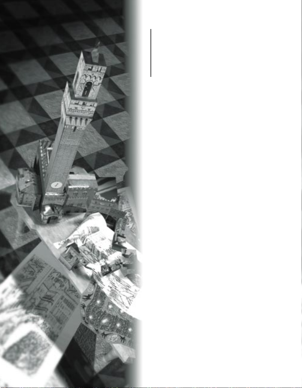
The Canoma Workspace
This section leads you through the Canoma
Workspace.
The first thing you’ll notice about Canoma is
that it doesn’t have traditional floating palettes
and toolbars. All of Canoma’s features are
integrated into the Workspace, whic h takes over
your entire screen. This helps keep everything
uncluttered and easy to locate.
On Windows, Canoma always runs maximized.
You can’t reduce the window size , although you
can minimize the Canoma window, using the
minimize control or switch applications, using
AL T-TAB or the application buttons in the Task
Bar. On the Macintosh, you can switch
applications by clicking inside the window for
the other application or by using the
Application List.
The Canoma Workspace is very flexible. Several
controls “float” over the Workspace and can be
moved by dragging them to other locations on
the application workspace.
The Canoma Project Window
The Canoma Project Window is a square
shaped window inside the Canoma application
window. It’s where you construct and view a
Canoma model.
The Project Window is used when you edit
your models, manipulating object wireframes in
Edit mode. It’s your work area where you’ll pin
3D objects to picture elements. The Project
Window can be resized to suit your needs (grab
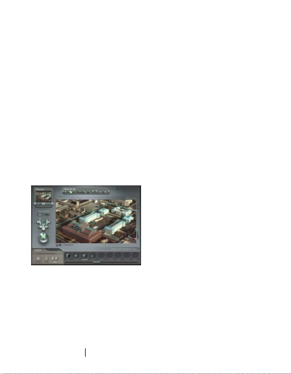
The Canoma Workspace takes over your screen and
provides access to the Canoma controls.
Your operating system’s standard menus and
windows are still available from within
Canoma. You can switch between Canoma and
other applications, such as 2D paint programs,
Web browsers, or 3D programs.
Application Overview
24
it by the lower left corner) and moved to
another part of the Canoma workspace (by the
title bar.)
The Canoma Project Window is where you view your 3D
models.
The Canoma Project Window is where you construct 3D
model.
The Project W indo w is also where you vie w the
3D models you create. The vie w you see of y our
model in the Project Window is taken through
a stationary “camera.” You can reposition the
Canoma camera in order to view your model
from different angles or distances. When you
view a 3D model, y ou’re in a three dimensional
space. That means you can even view your
model from below or above.
Just outside the Project Window are some
information displays and buttons. Along the
top of the window is the title of your project
and its size. To the top right of the window are
three buttons that toggle display options on
and off. To the bottom right of the window are
buttons that let you change the color for
program elements such as the background,
selected objects, unselected objects, objects in
the stress display, shadows, and object
constraints.
Camera Controls
Use the Camera Controls to change the
position and function of the viewing camera.
Tip
The Edit and View buttons switch between:
• Edit mode, where you can see the
wireframe objects that make up your
model and
If you’re familiar with Bryce 3D
or Poser by MetaCreations, the
Camera Controls feel very
familiar.
25
Canoma
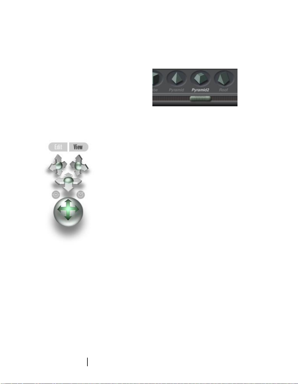
• View mode, where you can see the
untextured or textured 3D model.
The Camera Crosses let you move the view of
the camera specifically along X, Y, and Z axis.
The Camera Trackball lets you rotate the
camera in any direction and around any axis.
The Banking and Field of View control spheres
tilt your Camera and act like a wide-angle lens
control. Refer to “Positioning the View of Your
Model” on page 102 for more about positioning
the camera around your model.
Use the Camera Controls to adjust the position of the 3D
viewing camera.
The Creation Tab
The Creation Tab contains the 3D objects, like
boxes, rectangles, and even editable polyline
contours. Select one of these 3D objects,
position it, then “pin” it to an element in your
photograph. Once pinned into place, Canoma
uses that placement information to create a 3D
model, which can then be “covered” with the
pixels from your photographs.
Use the scrollbar on the Creation Tab to view all the
objects you can choose.
Refer to “W orking with Objects” on page 77 for
more about the Creation Tab.
The T oolbar
The Canoma Toolbar holds the tools you’ll use
to manipulate objects, view your work, and
apply or edit textures. Click a button to activate
that tool.
The Toolbar contains (from left to right):
•
Arrow
(select, pin, or apply beads)
Glue
•
•
•
•
•
(glue objects together)
Zoom
and
Pan
(move into, away from, or
around your scene)
Point Pen
points)
Texture Brush
level)
Quick and Quality Textures
photograph pixels as textures for your 3D
scene)
(add/delete polyline contour
(change textures at a pixel
(apply
Application Overview
26
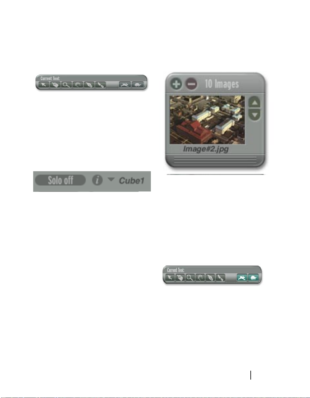
When a tool is selected, it is highlighted in the
Toolbar. At the top of the Toolbar is a title that
identifies which tool is active.
The Canoma Toolbar.
Selecting Objects
You can use the Object List to easily select an
object in your scene. The Information button
brings up a dialog of object settings for the
selected object. You can even switch into Solo
Mode, where it’s easier to see just the object
that you’re working with.
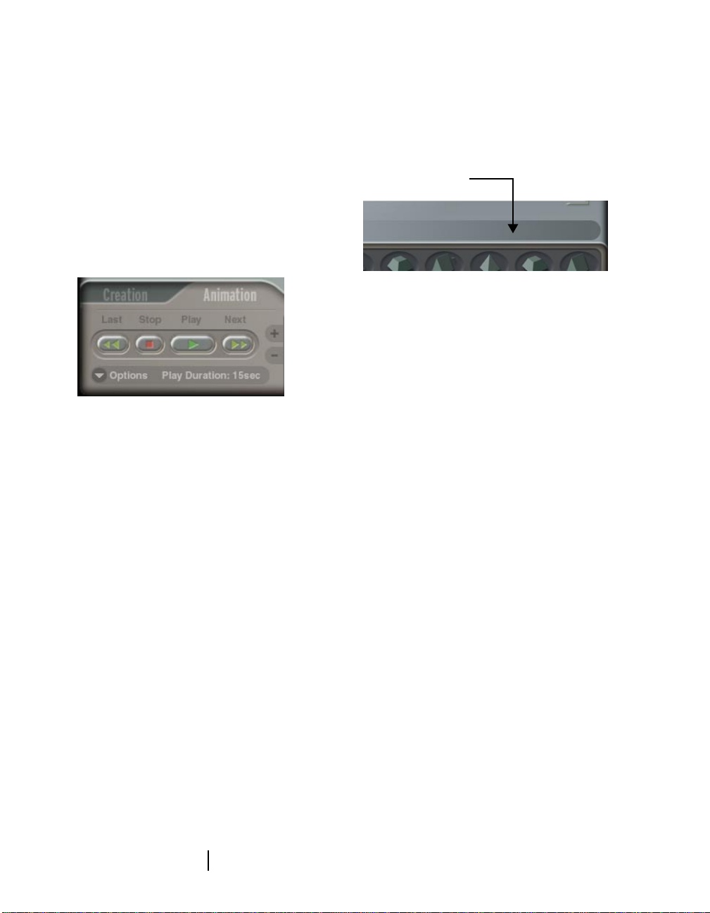
project. Refer to “Using 2D Source Images” on
page 74 for more about using the 2D Image
Views window.
The 2D Image palette.
Click the Information button for object settings, then use
Solo Mode to focus on one object at a time.
2D Image Palette
A thumbnail of your photograph is displayed
on the 2D Image P alette. This is a thumbnail of
the active image. The 2D Image Palette opens
downward to reveal all the photographs in your
Texture Controls
The Texture Controls apply the pixels of your
photograph to your 3D model. You can use
Quick Texture (fast) or Quality Texture (slower,
uses more memory, but looks better.) You can
also use the Texture Resolution popup to
choose a resolution setting for the textures you
apply.
Choose Quick or Quality Texture, as well as a resolution
setting.
Refer to “Working with Texture” on page 97 for
more information about adding Texture.
27
Canoma
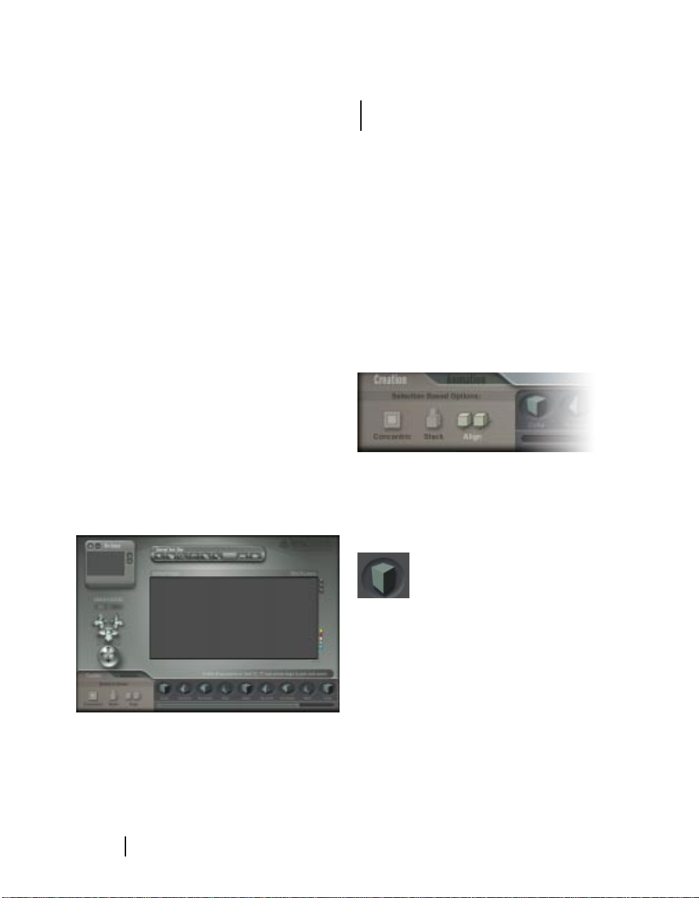
The Animation T ab
The Animation Tab holds the controls you need
to use in order to quickly define key frames and
set options to create an animation. Move the
camera, take a “snapshot,” move the camera,
take another snapshot, then Canoma completes
the work by interpolating between the
keyframes you’ve snapped or “filling in the
gaps.”
The Animation Controls.
each. Use Status Tips to “browse” around the
work area and become familiar with Canoma
tools, palettes, and dialogs.
Check here for Status Tips
Status Tips help you become familiar with Canoma tools,
palettes, and dialogs.
About Canoma
You can view information about which version
of Canoma you are using.
The Animation Tab contains controls for
adding and deleting keyframes, a looping
option, a way to set the playback duration, and
buttons for previewing your animation. Refer to
“Previewing an Animation” on page 117 for
more about the animation controls.
The Menu Bar
The Canoma Menu Bar contains eight menus:
the File menu, the Edit menu, the View menu,
the Model menu, the Texture menu, the
Animation menu, the Window menu, and the
Help menu. These menus provide another
method of access to the Canoma feature set.
Status Tips
As you move the cursor over an element of the
Canoma workspace, text in the lower right
corner of the screen explains the purpose of
To see Canoma information:
•
Click the word Canoma.
Accessing the
MetaCreations Web Site
You can access the MetaCreations Web Site
directly from within the Canoma program.
To access the MetaCreations Web Site:
•
Click the word MetaCreations. This
launches your browser and opens the
MetaCreations W eb Site.
Application Overview
28
3
Tutorial
What’s in this Chapter:
Welcome. . . . . . . . . . . . . . . . . . . . . . . . . . .30
Creating a 3D Model . . . . . . . . . . . . . . . . .30
Filling in the Details . . . . . . . . . . . . . . . . .35
Creating a Building Model. . . . . . . . . . . . .42
Aligning Objects Precisely. . . . . . . . . . . . .46
Picking Up Speed . . . . . . . . . . . . . . . . . . .50
Canoma
User Guide
Welcome
W elcome to the Canoma Tutorial. These lessons
are designed to introduce you to the major
features and functions of Canoma. The main
goal of the tutorial is to teach you all the basic
techniques you’ll need to use Canoma to create
3D models from 2D images.
Each lesson builds upon skills learned in the
previous lessons. At the beginning of each
section is a list of what you have learned up to
that point.
Creating a 3D Model
The first thing you need to do is launch the
Canoma application. Once it appears, Canoma
displays the Workspace in its default
configuration.
For these tutorials, you may want to leave the
controls in their default positions. Refer to
“Using the Canoma Workspace” on page 75 for
more about configuring the Canoma
Workspace.
Note
For the sake of clarity in this
manual, we used higher contrast
and larger pins in illustrations
than you will see in the Canoma
product.
Lesson1: Pinning Corners
To create your first 3D model:
1
Start Canoma.
2
Select
File menu > New
menu > Add Image
Tutorials: tutorial1.jpg
3
Click the Creation tab.
The Creation Tab.
4
Click the Box object. A red wireframe of a
Box is displayed. (Do not click any
Selection Based Options.)
, then select
and open
.
Canoma:
File
The Canoma workspace.
Tutorial
The Box object.
30
Selecting a Box adds a wireframe object of a box to your
project.
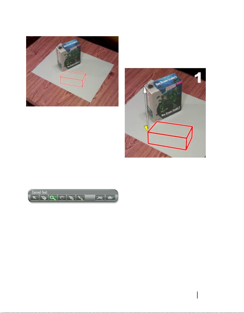
To start pinning:
1
Drag the box wireframe close to the Ray
Dream Studio 5 box.
2
Click the Zoom button on the Toolbar and
click the Ray Dream Studio 5 in the
picture. Zooming in makes the next step
easier. (Use the Pan tool—the hand button
on the Toolbar, if you can’t see both the
wireframe and the Ray Dream Studio box.)
The Zoom button.
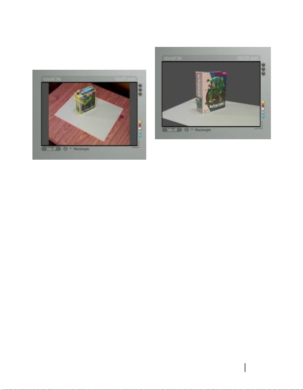
3
Click the Select button (the arrow) on the
Toolbar, then click and drag a corner of the
wireframe to a corner of the Ray Dream
Studio 5 box. A triangle appears when the
cursor is over a corner of the wireframe.
Click and drag a corner of the wireframe to a corner of the
Ray Dream Studio 5 box.
This process feels like pinning the corners
of a springy wireframe to a tackboard using
push-pins. If you think you made a
mistake, you can always Undo (Cmd/Ctrl +
Z.)
That's really the main goal—pin as many
corners of the wireframe as you need to get
a reasonable match between the wireframe
and the underlying photograph.
31
4
Click and drag the remaining corners of
the wireframe to corners of the Ray Dream
Studio 5 box, as shown in the following
Canoma
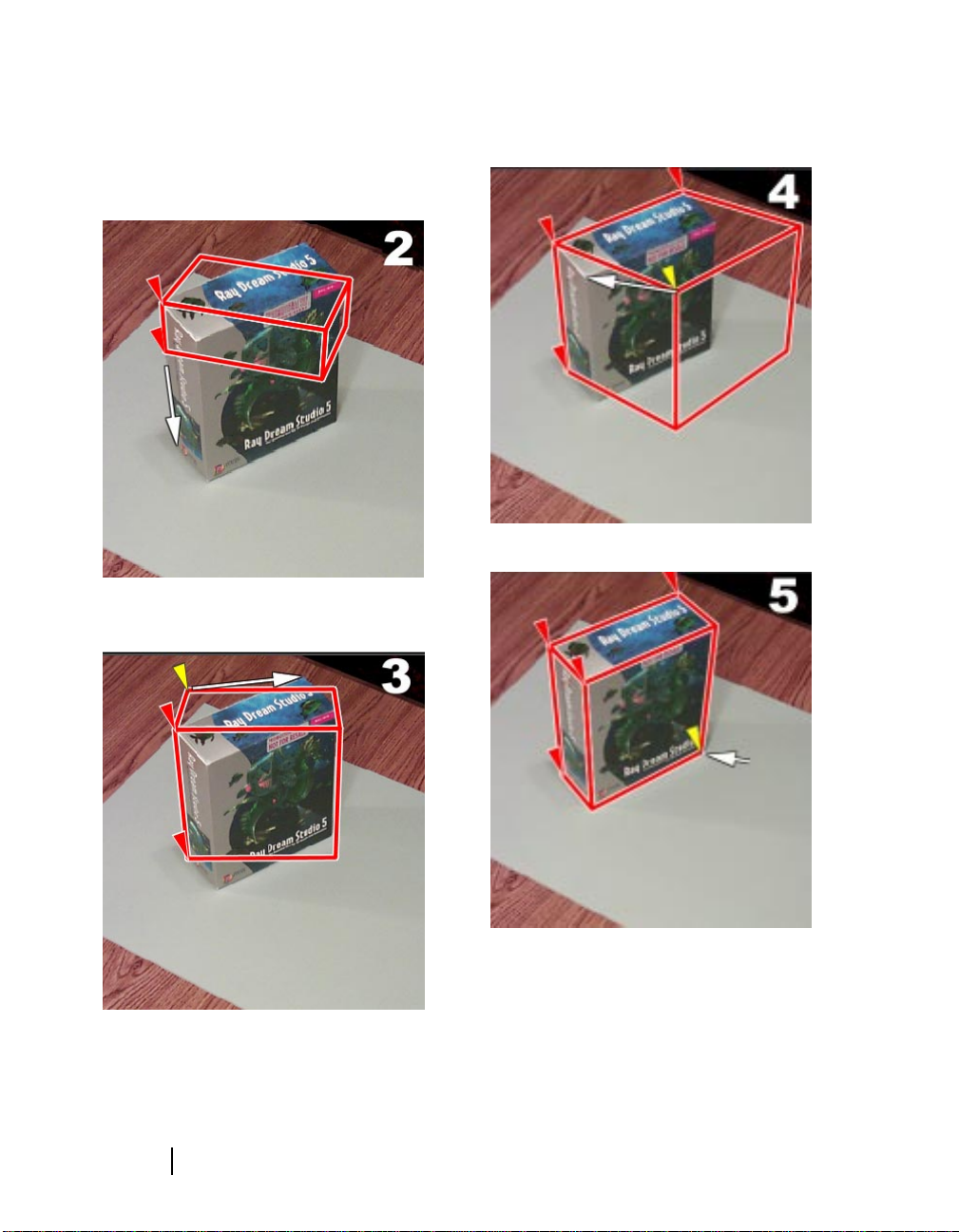
illustrations. Drag each corner in the same
sequence as is shown below and try to be
fairly precise.
Drag each corner of the wireframe to a corner of the Ray
Dream Studio 5 box.
Drag each corner.
Continue to drag corners of the wireframe to corners of the
Ray Dream Studio 5 box.
Tutorial
Try to be reasonably precise.
32

Drag another corner.
Lesson 2: Viewing Progress
To look at the 3D model:
1
Click and drag across the trackball
controller . Y ou’ll see a shaded 3-D box with
the correct dimensions. As you drag the
trackball, the camera rotates around the
box.
Drag the trackball to rotate the model.
2
Reset your viewpoint to the one shown in
the 2D photograph by clicking on the
photograph's thumbnail.
Click to return to the viewpoint in the 2D photo.
33
Canoma

3
Click Edit to switch back to Edit mode.
The Edit/View buttons switch between Edit and View
modes.
Lesson 3: Adding Textures and a
Ground Plane
To add texture to the model:
3
Click the Horizontal Rectangle object.
1
Click the Quick Texture button (the rabbit)
on the Toolbar. This applies textures from
the photograph and automatically switches
to View mode.
The Quick Texture button maps pixels directly from the
photograph and switches to View mode.
Texture enhances the model, but the box
still looks like it’s "flying in space."
To add a ground plane:
1
Click Edit to return to Edit mode.
2
Click the Creation tab.
Use a rectangle for the gray poster board. (Notice that,
because it’s not selected, the Box object wireframe is now
yellow.)
4
Pin the corners of the rectangle to the
corners of the gray poster board
underneath the Ray Dream box.
Pin corners.
Tutorial
34

5
Click the Quick Textures button to add
texture to the ground plane. The result is a
pretty realistically textured 3D model on
gray poster board.
Filling in the Details
The Story So Far
You learned the basic principle of the Canoma
program—pin wireframes to photograph
elements. You also learned how to view, rotate,
and apply texture to your model.
In the following section, you’ll learn how to fill
in areas that are not textured, by adding
information from additional photographs.
Lesson 1: Adding a Second
Image
Create textures and the box is no longer floating.
6
Use the trackball to preview & rotate your
model in 3D.
Rotate your 3D model.
Using just a single photograph, Canoma could
not create textures for the back sides of the box
or for the obscured area of the ground plane.
Now that you know how to go from wireframe
mode to View mode and back, it’s time to add
more textures.
You can add images from different viewpoints
to fill in the "bald spots" on any model. Later,
we’ll discuss other tricks for filling in areas
where you have no additional photographic
information. For this tutorial, a single
additional photograph, taken from behind the
box is used to complete texturing the model.
This lesson starts where the previous ended. If
you still have that project file open, skip ahead
to “To load another photo:” on page 36.
To open an existing project:
1
Select
2
Open the file
finished1.3dv
File menu > Open
Canoma: Tutorials:
.
.
35
Canoma

3
Click the Quick Textures button.
The Quick Textures button.
4
Use the trackball to rotate the box, so you
can see the back of the box. The back of
the box is untextured. To add texture
information for the back, you need to add a
photograph of the back of the box.
Your task is to make the wireframe match
this second photograph. Always look at
how the wireframe and the photo line up,
then use the trackball to roughly adjust the
alignment. Only then can you start using
pins.
Aligning the wireframe first saves a lot of
effort (far fewer pins are needed) and also
makes Canoma’s mathematics more stable.
Roughly align the new wireframe to the second
photograph, BEFORE you start pinning.
The back of the box and the ground plane behind the box
are untextured. This is because Canoma has no texture
information for these areas.
To load another photo:
1
Click the + on the 2D Image Palette and
load
Canoma: Tutorials:tutorial2.jpg
2
Click the Creation Tab.
3
Click the box object.
Wait! Do not start pinning!
A new wireframe is now superimposed on
the second photo, but the alignment is all
wrong.
Tutorial
.
To align the wireframe:
•
Use the trackball to rotate the whole model
about 180 degrees, so y ou are looking from
roughly the same viewpoint as the second
photograph. Notice how the program
snaps back from Preview Mode to Edit
36

Mode as soon as you let go of the trackball.
It only does this during rough alignment
(before any pins have been placed.)
First, rotate the whole model about 180 degrees
To pin and texture the second image:
1
Place pins on the corners of the rectangle
and the box. Place pins first on those
corners where the fit is worst.
As you add pins, the rest of the wireframe
soon fits the photograph.
Add pins and the wireframe soon fits the photo.
2
Switch to V iew mode , either b y clicking the
View button or by clicking the trackball.
The 3D camera position matches the
photograph quite well.
.Now that the wireframe is more closely aligned, you can
start pinning.
Don’t worry about getting the model
perfectly aligned. Roughly the same
viewpoint is fine. If you can see the correct
face of the box, you’re OK.
After you release the trackball, the
superimposed wireframe already matches
the second image much better.
37
3
Click the Quick Textures button (the
rabbit) on the Toolbar to generate textures
based on both photographs.
The back side of the Ray Dream Studio 5
box, as well as the previously obscured
(white) pieces of the ground plane are now
filled with texture. Your model might have
some white boundaries or visible seams.
More precise pinning helps reduce that,
but there’s a special texturing tric k that can
also improve the texture quality. More
about that later!
Canoma

4
Use the trackball to verify that you have
texture all around the 3D model.
The flat CD is visible from the front, too.
Fully textured.
Lesson 2: Modeling Nearby
Objects
Notice that there is a CD case behind the Ray
Dream Studio 5 box. This is very typical of real
world examples. As you add photographs, you
may discover objects that were partially or fully
obscured. When that happens, you can choose
to model the objects. If you don’t model them,
their image is flattened onto other objects.
Look carefully at the CD case’s texture in the
3D preview. It looks like a truck drove over it.
Your next task is to model the CD case. To do
that, you’ll want to take a look at things up
close.
To model the CD case:
1
Click Edit to switch back to Edit mode.
2
Click the Zoom button on the Toolbar, then
click and drag the cursor over the area
where the CD is located. This defines a
rectangular area to zoom in on.
The CD case is flat.
Tutorial
Drag the Zoom tool to define a zoom area.
38

The CD case close up.
3
Create a box.
4
Pin the new wireframe to the CD case,
three or four pins should be enough.
5
Click the View button and verify the
existence and size of the new 3D object.
Check the new CD case model in View mode.
Up until now, you’ve used Quick Texture.
Canoma can also create high-quality
textures. Quality Textures compensates for
brightness differences between
photographs that can show up as seams. It
also fills in white gaps for which there is no
available information. Quality texturing
takes longer, but it looks better.
Pin the wireframe to the CD case.
To use Quality Texturing:
1
Select
T exture menu > Quality Resolution
and choose a 1:1 resolution setting from
the popup list.
2
Click the Quality Texture button (the turtle)
on the Toolbar.
Click to turn on Quality Textures.
39
Canoma

After textures are generated, they look
better (although it does takes longer to
generate them.)
Lesson 3: Adding a Close-up
Image
You could stop there, but what if you need
better textures for the front of the Ray Dream
Studio 5 box? You might want to animate walkthrough, and for that y ou’ d w ant more detail. To
add that detail, you’ll add yet another image.
The image you’ll add does not show any new
information, but it does show the front of the
box in more detail.
You can imagine doing something similar with
architectural photographs:
• first create a model using an aerial
photograph
• then add detail with close-ups shots taken
at ground level.
To position a wireframe using beads:
1 Move the cursor over any edge (rather than
a corner) of the wireframe. A little disk
appears.
2 Click on the edge of the wireframe to
create a bead and drag it to the edge of the
gray ground plane.
To add and pin the third image:
1
Click the + on the 2D Image Palette and
load
Canoma: Tutorials:tutorial2b.jpg
.
2 Roughly align using the Trackball.
3 Click the Ra y Dream Studio box to select it
and pin the visible corners.
4 Click the gray ground plane to select it, but
don’t start pinning.
Close-up views often have the same
problem. You just can’t see the entire
photo element you previously modeled. In
this third photograph, none of the gray
ground plane’s corners are visible.
You can use a second (of three) Canoma
tools to position the wireframe for the
ground plane. These tools are called beads .
Tutorial
Use beads to position the wireframe for the third image.
3 Now switch to View mode.
4 Click the Quality Textures button, and
select a 1:1 resolution.
40

This time Canoma is going to work for a
while. Once textures are complete, you can
zoom in on the result. The texture on the
front of the box is noticeably improved.
2 Click the Texture Brush in the Toolbar.
The T exture Brush
3 Click the face of the Ray Dream box.
Canoma opens a 2D editing program.
Use beads to position the wireframe for the third image.
Lesson 4: Editing Textures
Why stop now? You can edit the texture on the
Ray Dream Studio box, using a 2D pixel editing
tool, such as Painter or Photoshop . You can edit
the image in 2D ("head on" view), then Canoma
automatically displays the results of your edits,
in proper perspective.
Note
When you edit texture, Canoma
saves a file of the resulting edit in
a subfolder, inside your main
project folder. If you create a
layered file during editing, you
may want to save a version of that
file in another location, just in
case you need to do any
additional editing.
Note
Since this is the first time you’ve
used the Texture Brush, Canoma
asks you to choose a 2D pixel
editing program, such as Painter
or Photoshop. You can also select
the application and 2D file format
using File menu > Application
Preferences.
4 Make a change to the image—change the
color , add some text, or retouch something .
You can change the resolution, but don’t
change the aspect ratio.
5 Save your work. Save a flattened image file,
to the same filename as the original. If the
original was a JPG file and you added text
or other layers, be sure to flatten the image
before saving.
6 Click back inside the Canoma’s program
window.
To edit textures:
1 If necessary, click the View button to
switch to 3D Preview mode.
41
Canoma

The edited texture is displayed in proper
3D perspective.
You can edit the texture with your favorite image editing
tool
Creating a Building
Model
The Story So Far
In the following section, you’ll try a bigger
model. This section of the tutorials takes a little
longer, so reserve some time. The instructions
describe tricks for modeling some of the
buildings. You can go further and model other
buildings for additional practice. A finished
example file—Canoma: T utorials:
finished3.3dv—is available for you to study.
Lesson 1: Starting with One
Object
To model the first photograph:
1 Start Canoma.
2 Select File menu > New, and open
Canoma: Tutorials: tutorial3.jpg.
You learned how to add photographs to an
existing project, to fill in the gaps. You also
learned how to roughly align the wireframe to a
new photograph using the trackball (before any
pinning!) You learned that fewer pins are
needed in the additional photographs. You no w
understand the differences between Quick and
Quality Texturing and between low and highresolution settings. You learned how to edit
textures with a 2D pixel editing program.
You may have noticed that a red wireframe is
the "active" or selected one currently being
pinned, all others are yellow. You know how to
add close-up pictures to get crisper textures
and how to add beads rather than pins when
you cannot see the corners.
Tutorial
Open tutorial3.jpg.
Start by modeling the main white building.
42

To add the first object:
1 Use the Zoom tool to get a close-up view of
the white building for better precision.
Add and pin the first object.
2 Click the Creation Tab.
3 Select the Box object.
4 Pin the box wireframe to the main part of
the white building.
Notice that the building has a notch out of
the left front corner. It is not a full box.
Do not model the notch! Keep it simple.
This is a typical trade-off in Canoma
between "getting fast results" and "making
it correct". Quite often, the fast results are
good enough.
Since you can’t actually see the corners of
this building, you must estimate in order to
put pins where you think the corners are
located.
In the last tutorial we suggested that you
only place pins where you can see real
corners. Here, by looking at the top edges
of the building, which are very visible, you
can safely estimate the location for the
pins.
Notice that there are structures on top of the
white building. Now that the base structure is
pinned, it’s time to model some of the
structures on top.
It is important to understand that by default, all
objects you create sit on the ground, at height
0. Sometimes, such as in this case, you may
need to put objects on top of other objects.
To model objects that are on top of other
objects:
1 Make sure the white building wireframe is
selected, i.e. that the wireframe is red. If it
is yellow, click to select it.
2 Click the Creation Tab.
3 Click Stack in the Selection Based
Options, then select the Box object.
Using the Stack option places a new object on top of the
active object.
43
Canoma

4 Pin this box to the relatively flat
superstructure that sits on top of the
building.
Pin the “on-top” box to the flat structure on top of the
building.
Lesson 2: Completing the Job
Now that you’ve modeled part of the building,
you can go on to model the rest of the
photograph.
5 In View mode, click Quick Texture.
Add Quick Texture.
To create the ground plane:
1 Click the Creation Tab.
2 Click the Floor Rectangle object to create a
flat rectangle that’s large enough to be the
ground plane for your entire scene.
3 In View mode, click the Quick Textures
button.
Continue to model structures in the photograph.
A Few Things to Remember
• In general, the first few objects really help
Canoma determine the camera viewpoint
and perspective. Larger objects, with well
defined perspectives allow better operation
than smaller objects or objects viewed
head-on.
• Remember to always model objects from
the ground up. First model the base of a
building, then create a pyramid or roof on
top of that.
• You can also establish perspective early on
by using a temporary object, suc h as a large
ground plane, to show Canoma the
vanishing directions (how parallel lines
such as the roads converge.) You can delete
the temporary object after the rest of your
modeling is complete. Like removing a
scaffold after real-world construction.
Tutorial
44

Reducing Confusion
As you add more objects, some with objects on
top of them, the wireframe display can get
cluttered. Here is a trick to reduce the
confusion.
To use Solo Mode:
• Click the Solo Mode button to dim all
wireframes except the one you are
currently working with (the selected one,
in red.)
The Solo Mode button.
This color-coding lets you see where objects are
located and also lets you quickly select one for
further work, without ha ving to switch betw een
Solo and regular editing Mode.
The Solo Mode button is only available
when there is more than one object in your
scene.
T o s witch fr om Solo Mode to normal editing:
• Click the Solo Mode button again.
Even while you are in Solo Mode, when you
move the cursor over other areas of the
photograph, existing, but currently hidden
wireframes, temporarily show up outlined in
yellow.
Use Solo Mode to reduce confusion.
The final project.
Lesson 3: Navigating Through a
Model
You know how to use the trackball to rotate a
3D model. There are other ways to navigate
through a model.
45
Canoma

Using the Cross Control
Camera Cross controls let you move the view of
your model along specific axes. When you’re
using these controls, the view does not tilt or
rotate from its original position. It only moves
up, down, back, or forward.
Canoma’s Field of View control automatically
adjusts the distance, so that objects in the
center stay about the same size.
The Field of View Control.
The Cross Controls.
Just play around with the Cross Controls - you
can always reset to the viewpoint of a particular
photograph by clicking on its thumbnail.
The Banking control sphere tilts your Camera
(really rotating the camera on the Y axis,)
creating the effect of a tilted horizon. This
control is great for creating tilted airplane
cockpit views. Banking simulates a Roll action.
The Banking Control.
The Field of View control sphere acts like a
wide-angle lens control. The higher the setting,
the wider the field of view for your lens.
Tip
You can also navigate right in the
Project Window. Refer to “Using
the In-View Navigation Controls”
on page 104 for another way to
navigate around your model.
Aligning Objects
Precisely
The Story So Far
In the previous lessons, you learned how to
create objects on top of other objects. You
learned how to use Solo Mode to help you
remain focused on desired objects. You learned
how to add a ground plane even when there are
no good corners visible and how to use beads
instead of pins when you need to model a
partial object. Finally, you learned how to
navigate through your models using the Cross
Controls, the Banking Control, and the Field of
View Control.
In the following lessons, you will learn how to
use glue to align objects precisely.
Tutorial
Lesson 1: Using Glue
You are about to make a model of a building in
Washington, DC. You will use glue to align
objects precisely.
46

To start with the 2D image:
1 If you haven’t already, select File menu >
Close to close the previous tutorial.
2 Select File menu > New.
3 Load Canoma: T utorials: tutorial4.jpg.
To start modeling:
1 Model the base of the red building, using a
Box.
You cannot really see the front bottom or
the back top corner, so you can use beads
for the edges there.
Box and pin it. Use a bead to raise the top
of this second wireframe to the proper
height.
Use a bead to estimate the edges.
Model the base with a box.
2 With the first wireframe still selected, click
Stack and Aligned in the Selection Based
options on the Creation Tab, then create a
Tip
The next step is to model the small
structure on top.
Since you know that each section
of the Red building is aligned
with the rest, using Stack/Align
for the second wireframe tells the
program that the elements are
aligned, which creates a better
model.
3 With the second wireframe still selected,
click Stack and Aligned in the Selection
Based options on the Creation Tab, then
create a Box and pin it.
Since the bottom corners of the third box
coincide with the top of the second box,
you can use glue rather than pins to give
them approximately the same location.
To glue the third box to the second:
1 Click the Glue button (the glue bottle) in
the T oolbar .
47
Canoma

2 Click and drag a bottom right corner of the
topmost box.
4 Now do the same thing for the right-back
corner of the roof and the left-front corner .
3 Move that corner over the edge of the
second box. A little yellow bead is visual
feedback that you are gluing to the edge of
the box.
4 Let go of the mouse button.
Circles tell you that the object is glued to the one below.
The next step is to create a roof on top of the
topmost box.
To glue on the first roof:
1 With the topmost wireframe box selected,
click Stack and Aligned in the Selection
Based options on the Creation Tab, then
create a Roof.
2 Click the Glue button (the glue bottle) in
the T oolbar .
3 Click on the right-front corner of the roof
wireframe and drag it to the top-right-front
corner of the topmost box.
You’ll see a yellow pin that indicates you
are gluing, rather than pinning, the roof to
the box. When you release the mouse
button, a circle shows that the corner is
glued.
Note
Do not pin or glue the left-back corner of
the roof. Since it can’t be seen, it’s not a
good idea to introduce a pin or glue that
could easily be inaccurate.
With three corners glued to the box, the roof’s orientation
is fixed.
In real life the roof extends
beyond the edge of the building.
Model the roof to be the same
length and width as the building.
Don’t force the roof out past the
edge of the box with a pin. Refer
to “Avoiding Model Stress” on
page 96 for more about how to
avoid introducing unnecessary
stress into your Canoma model.
5 Now fix the height of the roof. You could
use a pin in the front top corner or a bead
on the top edge, but a bead is better in this
case.
6 Switch to View mode to see the results. A
perfect fit. If things went awry during this
step, use Undo (Cmd/Ctrl+Z) and try again.
Now it’s time to put a roof on the second
level of the building.
Tutorial
48

To add a final roof:
1 Select the second Box that you created (the
middle level of the building.)
2 Click Stack and Aligned in the Selection
Based options on the Creation Tab, then
create a Roof.
W ait! the orientation of the Roof wireframe
is all wrong. That’s probably going to
happen a lot, but it’s easy to correct the
orientation.
3 W ith the roof wireframe still selected, click
the object information button or select
Edit menu > Get Information.
The object information button.
The Object Information dialog is
displayed.
4 Click the Rotate by 90º around Y-Axis
button.
5 Now that the orientation of the wireframe
is correct, glue the roof as you glued the
previous roof. Glue only the three visible
corners of this part of the building. Model
the roof to be the same length and width as
the building, ignoring any "real life"
overhang.
6 Use a bead to "pull up" the roof to the
correct height.
7 Switch to View mode, select Quality
Textures, with a 1:1 resolution and create
the textures for your model.
8 Congratulations!
The Object Information dialog.
The final results.
49
(If you get good at this, you can do this
whole part of the tutorial, with texturing,
in under two minutes. Refer to “Setting
Selection Based Options” on page 88 and
review the Concentric option for
information about another feature that can
save you time when you’re creating
models.)
Canoma

Picking Up Speed
The Story So Far
You learned how to use glue for precise
alignment (both corner-to-corner and cornerto-edge). You learned how to notice and avoid
inconsistent input.
In the following lessons, you’ll learn how to
speed up modeling by duplicating similar
elements in a photograph. You’ll learn to use
glue to precisely connect shapes.
You’ll learn the importance of modeling large
scale features first, ev en if your early models are
only used as stand-ins, for more detailed
models later. After establishing good
perspective, you can delete temporary objects
and replace them with successively more
detailed models.
Lesson 1: Duplicating Similar
Elements
To start with the 2D image:
1 Select File > New to create a new project.
perspective for your scene - as you add
more boxes, they should "fall into place"
with only a few pins. Instead of completing
this building, proceed with one of the two
identical H-shaped buildings right behind
the red one.
2 Use a single box for the first H-shaped
building and pin it into place.
Use a single box for the first H-shaped building.
Tip
If you zoom in on a building
before you create an object, the
object gets created close to where
you need to place it.
2 Load Canoma: Tutorials: tutorial5.jpg.
You’ll recognize the red building from the
previous tutorial, but no w you’ll model the
whole area surrounding the red building.
The trick is to model large structures first,
as that establishes good perspective for
Canoma. Only then should you proceed
with more detailed models.
To model around the red building:
1 Create and pin a Box on both the larger
building at the top of the photograph and
the red building in front. This sets the
Tutorial
3 Assume that the two H-shaped buildings
are symmetrical and aligned. Instead of
just using create box, keep the H-shaped
building’s box selected and press Shift +
Cmd/Ctrl+D to create an aligned duplicate
of the selected box.
50

4 All you need to do is pin this duplicate to
the other H-shaped building. Two pins are
probably sufficient, because all other
dimensions are known to Canoma from the
first H-shaped Box.
6 Use aligned duplicate (Shift + Cmd/Ctrl +
D) again for the second square-shaped
building.
Use aligned duplicate (Shift + Cmd/Ctrl + D) whenever
possible.
Use Aligned Duplicate (Shift + Cmd/Ctrl + D) to create
the second H-shaped building.
Use Edit menu > Duplicate when you are
sure two objects have the same
dimensions.
Use Aligned Duplicate (Shift + Cmd/Ctrl +
D) when the dimensions and alignment are
both identical. This reduces the number of
pins needed to place wireframes and at the
same time makes your 3D model more
precise.
5 Create a box for the first small square-
shaped building.
Now you have 5 Boxes across the whole
picture.
Tip
It’s a good idea to model large
objects around the entire
photograph first, to establish
perspective. Don’t start modeling
in great detail in one corner of a
photograph, because it’s easy to
imprecisely place a pin, causing
Canoma to estimate a wrong
perspective.
51
Canoma

7 Rotate the model in View mode to check
whether the dimensions match your
expectations. This helps to verify whether a
reasonable perspective was established.
4 Use Align Duplicate to create a Box f or the
near end.
5 Create a Box for the center.
Verify perspective.
If the perspective seems squashed or
stretched, it’s probably off. If that happens,
it is probably best to start over. Which is
not so bad, since you’ v e only had to place a
few Boxes.
Lesson 2: Adding Detail
What if you want to model in more detail?
Once you are satisfied that Canoma has a good
perspective, you can delete the "stand-in" or
rough models you have just created, then
replace them with more detailed models.
To add more detail:
1 Select one of the H-shaped Boxes and
press the Delete key or select Edit menu >
Clear.
2 Zoom into that area of the photograph.
3 Create a Box and pin it to the far end of the
building.
Duplicate and Aligned Duplicate are your friends!
6 Since you know the building parts border
each other, click the Glue button on the
Toolbar to glue (not pin) top corners of the
center box to the nearest top edge of the
end boxes.
7 Now use a bead for the center Box’s bottom
edge, to slide it into the right place.
You could have modeled each of the 3
Boxes separately, but it would have been
more work and they might not have
aligned as nicely as they do now.
You can now model the second H-shaped
building in more detail, using the same
techniques.
Tip
As a finger exercise, complete the
red building model in the front.
Tutorial
52

Lesson 3: Adding a Ground
Plane
Finally, add a ground plane the same way you
did in the 3rd tutorial.
To create the ground plane:
1 Create a Horizontal Rectangle.
2 Pin the far corner to the street corner at
the far end (near the two red cars.)
6 Click Quality Textures buttons, with a
resolution of 1:1 to create the textures.
3 Use beads to stretch the rectangle around
all your buildings.
Parts of the rectangle now extend outside
the photograph - that's fine.
It’s OK if parts of the rectangle extend outside the
photograph.
4 Switch to View mode.
5 Select Texture menu > Mirror Textures.
This tells Canoma to “steal” the texture
from another place on the object, since
pixel information is not available.
Looking good!
7 Rotate the model. You may be surprised.
The back sides of the building, whic h were
not visible in the photograph, are now
textured. Canoma actually “mirrored”
textures from elsewhere and did a pretty
good job.
Before Texture menu > Mirror Textures is used
53
Canoma

After using Texture menu > Mirror Textures. Canoma
“steals” textures from a portion of the model where
textures are available, then applies them to non-textured
sides.
Tutorial
54

4
Canoma
Basics
What’s in this Chapter:
Setting Up Your Workspace. . . . . . . . . . . .57
Creating a Canoma Project . . . . . . . . . . . .60
Using 2D Images . . . . . . . . . . . . . . . . . . . .60
Creating 3D Models. . . . . . . . . . . . . . . . . .60
Adding Texture. . . . . . . . . . . . . . . . . . . . . .61
Creating Animations . . . . . . . . . . . . . . . . .61
Undoing Operations . . . . . . . . . . . . . . . . .61
Saving and Closing . . . . . . . . . . . . . . . . . .62
Importing, Exporting, and Rendering. . . .62
Canoma
User Guide

Introduction
This chapter describes how to setup Canoma
and shows you some basic techniques you’ll
need to know in order to create 3D models.
Customizing Canoma
Saving Workspace
Customizations
Canoma is intended to be a flexible, creative
tool, so there are many w ays you can customize
it to suit your style of working. Move toolbars
and palettes, resize the project window, or
choose a color scheme.
Setting Canoma Preferences
Set Application Preferences to suit the wa y you
like to work.
To open the Canoma preferences dialog:
•
Select
File menu > Preferences
the Application Preferences dialog.
to display
The Maintain Custom Configured Workspace
option toggles between discarding those
changes or keeping them from session to
session.
Save or discard changes you make to the workspace.
To save changes you make to the Canoma
workspace:
1
Select
File menu > Preferences
the Application Preferences dialog.
2
Click the
workspace
that the option is selected.
The next time you start Canoma, your
workspace is as you left it when the
application was closed.
T o discar d changes you make to the Canoma
workspace:
Maintain custom configured
option. A checkmark indicates
to display
Setting Canoma preferences.
Canoma Basics
56
1
Select
File menu > Preferences
the Application Preferences dialog.
2
Click the
workspace
displayed when the option is not enabled.
The next time you start Canoma, your
workspace is displayed in the default
configuration.
Maintain custom configured
option. No checkmark is
to display

Using the Active Guide
When you start creating objects and affixing
them to photo elements, you can get some help
from the Active Guide. This handy window
offers tips to pace you through the creation and
pinning of your first few primitives.
Select a default 2D pixel editing application,
such as Painter or Photoshop. The default 2D
pixel editing tool is opened whenever you use
the Texture Brush from the Toolbar to edit the
texture on the face of an object.
The Active Guide offers tips to help as you create and pin
objects.
To turn the Active Guide on or off:
1
Select
File menu > Preferences
the Application Preferences dialog.
2
Click the Display Active Guide option. A
checkmark indicates that the option is
selected.
to display
Choosing a 2D Image Editing
Application and Image Format
Make subtle or major changes to the texture of
a 3D modeled scene, using your favorite 2D
pixel editing program or use Canoma to keep
that 3D look, without creating a 3D scene. Edit
an area of texture, then have Canoma display
the results in proper 3D perspective. What a
time saver! Refer to “Retouching or Editing
Textures in 2D” on page 110 for more about
editing a perspective image.
Selecting a 2D editing application.
You can also select a Default File Type to be
used for the image files generated when you
edit textures.
To select a 2D image editing application:
1
Choose
2
Click the Browse button and navigate to
select a 2D pixel editing program.
3
Click Apply .
To choose a default 2D Image File Type:
•
Click the Image Format drop down list and
choose a format.
File menu > Preferences
.
Setting Up Your
Workspace
Working in the Project Window
In Edit mode, Canoma’ s Project Window shows
the active photograph and any 3D wireframe
objects you have created and placed. In View
mode, the Project Window shows your textured
57
Canoma

or untextured 3D model. Refer to “Using the
Canoma Workspace” on page 75 for more about
the Project Window.
Understanding the Toolbar
The Canoma Toolbar holds the tools you’ll use
to manipulate objects, view your work, and
apply or edit textures. The Toolbar can be
repositioned on the workspace. Refer to “The
Toolbar” on page 26 for more about the
Canoma T oolbar .
The Canoma Toolbar.
Changing Canoma Colors
The Project Window in 3D Preview mode.
Using the Camera Controls
The Camera Controls are used to position and
rotate the camera that views your model. They
can be repositioned on the workspace. Refer to
“Using Canoma Camera Controls” on page 102
for more information about how to use the
Camera Controls.
You can customize the colors that Canoma uses
to display application elements. Use the color
selection buttons outside the lower right corner
of the project window to select a color scheme
that works best for you.
To change the background color:
•
Click the Background Color button, then
select a color. The default background
color is dark gray.
Click to change the background color.
Y ou can move the Camera Controls to another place on the
workspace.
Canoma Basics
58

To change the color used to highlight the
selected object:
•
Click the Selected Object Color button,
then select a color. The default selected
object color is red.
Click to change the selected object color.
To change the color used to highlight
unselected objects:
•
Click the Unselected Objects Color button,
then select a color. The default unselected
object color is yellow.
Stress” on page 96 for more about using
the stress display to check for errors that
place stress on the 3D model.
Click to change the stress display color.
To change the color used for shadows:
•
Click the Shadow Color button, then select
a color. The default shadow color is light
gray. Refer to “Using Shado ws” on page 95
for more about wireframe shadows.
Click to change the color of unselected objects.
To change the color used for objects in the
stress display:
•
Click the Stress Display Color button, then
select a color. The default stress display
color is white. Refer to “Avoiding Model
Click to change shadow color.
To change the color used for highlighting a
selected object constraint:
•
Click the Selected Constraint Color
button, then select a color. The default
selected constraint color is cyan. When
59
Canoma

you move the cursor over a constraint,
such as a bead or pin, the selected object
constraint color is used.
Click to change the selected constraint color.
Creating a Canoma
Project
A Canoma project is made up of photograph(s)
or image(s) over which 3D primitives are
projected. Refer to “Working with Canoma
Projects” on page 76 for more about creating a
new project or opening an existing project.
Organizing the Project Folder
Using 2D Images
When you create a Canoma project, y ou’ll start
by loading a photograph. This first photograph
lays the groundwork for further work. Images
are stored in the 2D Image Views palette. The
2D Image Views palette can also be
repositioned on the workspace. Refer to “Using
2D Source Images” on page 74 for more
information about that palette.
If you need better textures for the front of a
building or the side of a box, y ou can add more
detailed texture by adding photographs. For
example, you might want to add detail for one
side of a building, to show what offices are
available. Refer to “Adding More Detail” on
page 98 for more about using additional
photographs to add detail.
It’s a good idea to create a project folder, before
beginning work on your 3D model. A main
project folder holds all of the photographs your
project requires, as well as the Canoma project
file (when saved.)
Because Canoma expects all project files to
reside at the same hierarchical level, do not
place photographs in a subfolder and take care
to save the project file so that it resides in the
main project folder. Any subfolders that are
required by the project are created within the
main folder by Canoma.
Canoma Basics
The 2D Image Palette.
Creating 3D Models
The goal of Canoma is to make 3D wireframe
primitives match underlying images. To do that,
you pin the corners of wireframe primitives,
such as boxes or pyramids, to get a reasonable
match between the wireframe and the
photograph. Refer to “Using the Canoma
Workspace” on page 75 for more information
about building 3D models. Refer to “Modeling
Objects” on page 120 for some interesting
modeling techniques.
60

Once created, you can view it as a 3D model,
using Canoma’s camera controls. Refer to
“Using Canoma Camera Controls” on page 102
for more information about viewing your
models.
Refer to “Retouching or Editing Textures in
2D” on page 110 for some great tips about
editing areas of texture in a 2D program.
Adding Texture
Adding texture is the process of mapping pixels
of an underlying image to the surface of an
object, without changing that object’ s geometry.
Canoma offers two types of texturing: Quick
Texture and Quality Texture. Quality texturing
compensates for brightness differences
between photographs that can show up as
seams. It also fills in white gaps f or whic h there
is no available information. Quality texturing
takes longer and takes more memory, but it
looks better. Refer to “Working with Texture”
on page 97 for more information about adding
surface textures.
Use the Texture Brush to select an area to edit in a 2D
pixel editing application, such as Painter or Photoshop.
Creating Animations
Animation is the process of recording the
motion of the camera as a 3D model is being
viewed.
To create an animation:
• Complete a 3D model.
• View it.
• While viewing, record keyframes.
Canoma creates a motion path from your
recorded camera movements and then
generates an animation. Refer to “Creating an
Animation” on page 116 for more information
about creating animations.
Undoing Operations
The Undo command and the Revert to Saved
command let you discard the effects of changes
you’ve made to your model.
Canoma uses pixel information from the photograph to
apply texture to a model.
You can Undo an operation up to 10 times in a
row. You can also Redo what you’ve undone. If
you’ve made changes and change your mind
completely, you can discard an y changes y ou’ve
made, without exiting the program.
61
Canoma

To undo the last operation:
•
Choose
Ctrl+Z).
To redo the last operation:
•
Choose
To revert to the last saved version of your
model:
•
Select
Edit menu > Undo
Edit menu > Redo
File menu > Revert to Saved
(or press Cmd/
.
.
Be sure to save the new project file so that
it resides in the same folder as the project
photographs. Canoma assumes that all
project files are at the same hierarchical
level.
If texture was edited with a 2D pixel
editing program, such as Painter or
Photoshop, the resulting files from those
edits are placed in a subfolder created by
Canoma. This subfolder’s name matches
the new project name. If you do not want
texture edits to apply to the copy, remove
the texture edit files or remove the entire
subfolder.
Saving and Closing
The Save command lets you save your work.
Saving the Project
To save a project file:
1
Choose
2
Use the Save dialog controls to choose a
location for your work, then click Save.
Be sure to save the project file so that it
resides in the same folder as the project
photographs. Canoma assumes that all
project files are at the same hierarchical
level.
To save a file under a different name:
1
Choose
2
Enter a new name and/or location in the
fields provided and click Save.
A copy of your work is saved, leaving the
original intact.
File menu > Save
File menu > Save As
.
.
Closing Canoma
To close Canoma:
•
Choose
Q/Ctrl+Q . When you close the application,
Canoma asks if you want to save your work.
File menu > Quit, or press Cmd-
Importing, Exporting,
and Rendering
Importing
Canoma supports the following 2D file formats
for import into your model:
• JPG
• TIFF (includes alpha information)
• PNG (includes alpha information)
• GIF (includes alpha information)
• PSD (includes alpha information)
• BMP (Win only)
• PICT (Mac only)
Canoma Basics
62

Exporting
When you export your Canoma model for use
on the Web or in another 3D program, Canoma
automatically creates a folder to hold the
various files that are created.
With Canoma, what you see is what gets
exported. If you edit textures after emitting a
model, those image files are not picked up by
the exported model. If Texture menu > Mirror
Textures is Off, untextured surfaces are
untextured in the exported file. If Texture
menu > Mirror Textures is On, untextured
surfaces will be filled with pixels from the
corresponding side.
Canoma supports the following file export
formats:
• MetaStream (for posting on the Web)
When exporting to MetaStream, two file
formats are generated:
• HTML which embeds (using the
EMBED tag) MetaStream output
generated by Canoma
• MTS file containing compressed
geometry and textures.
Double-click the HTML file to open the
output.
The proper usage of MetaStream objects is
as embedded objects in a HTML page. This
gives the page author full control over a
wide range of rendering and interaction
options described at the MetaStream Web
site (http://www.metastream.com). If you
were to just open a raw MTS file, the plug
in runs with all attributes set to default
values, which is unlikely to be correct for
all cases.
Textures generated by Canoma are already
lit (by real light) and do not need to be
additionally shaded by synthetic lights, so
texture shading is set to off.
Infini-D: If Infini-D is installed, the MTS
file appears with an Infini-D icon and
launches the application when doubleclicked, so just double-click the HTML file .
Make sure the path and the filename are
correct and that all required libraries are
available or an error message is displayed.
Should that happen, just open the HTML
file.
• OBJ file format (for import into Poser,
Bryce 3D , Ra y Dream Studio, and other 3D
programs)
Ray Dream Studio: The geometry and
textures import nicely, but the bounding
boxes are drawn incorrectly.
Poser: Exports to Poser Prop export a.pp2
file and several .bmp (Win)/.pict (Mac)
textures. You then need to manually copy
or move the.pp2 file to any immediate
subfolder of Runtime\libraries\props and
move or copy all the .bmp or .pict files to
<PoserAppDirectory>\Runtime\textures\.
The Canoma generated object or scene
appears in the list of props (without a
special icon) and the name you give the
prop. You can place & work with the prop
like any other. To make things simpler:
Keep shortcuts/aliases to the Poser texture
and prop type folders handy to where you
generate the prop file, then just drag the
files onto the shortcuts - faster than
hunting the directory down. One word of
caution: don’t name two Canoma
generated Poser props the same name or
you will overwrite part of the other props
textures.
Maxon Cinema: Maxon Cinema imports
the OBJ geometry ungrouped and
untextured.
NewTek Inspire 3D modeler: NewTek
Inspire 3D modeler loads the geometry
untextured.
63
Canoma

• VRML 2 (for use in Cosmo 2.1, Blaxxun
Community Client, Visscape Superscape
VRML, and 3D Studio Max)
Textures generated by Canoma are already
lit (by real light) and do not need to be
additionally shaded by synthetic lights, so
texture shading is set to off.
The VRML that is exported contains one
viewpoint for each source image and also
an extra one for the current 3D view
camera (which need not coincide with any
source image point of view.) Typically,
VRML browsers let you step between
viewpoints. Consult your Browser
documentation for details. For example, in
Cosmo 2.1, PgUP and PgDn go to the Next/
Previous viewpoint.
If you created an animation in Canoma, the
starting point of the animation gets
recorded in the VRML as a special
viewpoint called “T our . ” After selecting
“Tour” as your viewpoint in the VRML
browser, click anywhere in the scene to
start the animation you had in Canoma.
After the animation is finished, the “Tour”
automatically returns to the starting point,
ready for another “click” to start it again.
Canoma exports VRML files as text files.
Typically, these are not large compared to
the associated texture files, but you can
gzip the WRL file for extra compression,
using the 3rd party gzip software utility.
Remember to rename the .wrl.gz file
extension back to .wrl, even though it is
now compressed. Browsers use this
extension to route contents to the correct
plug-in (in this case VRML.)
If you import Canoma models into a 3D
modeler and the objects seem too bright,
either turn texture shading off altogether
or attenuate your texture light emission.
• Caligari trueSpace 3D
All objects are exported as one group. All
image viewpoints are saved as cameras in
TS4. The first four are opened as views in
the workspace. Canoma exports to .scn
files, to load scenes. If you want to create
separate reusable objects, load scene,
ungroup, and Save Selected Objects as
.cob files.
Due to a problem in TS4.0, some textures
may display black. Registered users can
upgrade to 4.1 by contacting Caligari
directly. This fixes the problem.
• AutoCAD DXF
Files exported as DXF may import into 3D
applications very small. In some cases, you
can adjust the DXF units during import. In
most cases, you should scale the model. In
a very specific case using Artifice Design
Workshop, the imported DXF model
imports objects ungrouped. Group the
model before scaling.
Rendering 2D Images
You can produce a 2D image of your Canoma
scene. When a 2D image is rendered, Canoma
automatically creates a folder into which it
saves any associated image files.
When you render an image, a popup menu
with output file size choices is displayed. Any
rendered image is locked to the aspect ratio of
your project window.
To render a 2D image of your model:
1 Select File menu > Render Image.
2 Set the desired size.
Canoma Basics
64

Rendering Animations
You can produce a QuickTime movie of camera
movements around your Canoma scene. When
an animation is rendered, Canoma
automatically creates a folder into which it
saves any associated animation files.
Note
When you render an image, a popup menu
with output file size choices is displayed. Any
rendered image is locked to the aspect ratio of
your project window.
At the time you render an animation, you can
edit the module, setting additional options,
including animation compression and frame
rate.
You can also select to output your animation as
a sequence of image files.
To render an animation,
QuickTime 3.0 must be installed.
It is available on the Canoma CD ,
or can be downloaded at
www.apple.com.
To render an animation:
1 Select File menu > Render Animation.
2 Set the desired size.
3 Select between outputting a QuickTime
animation or a series of keyframe images.
Selecting to output as a series of keyframe
images outputs single image files for each
keyframe (BMP on PC, PICT on Mac). This
generates as many single files as there are
frames in your movie.
4 Press Edit, to edit the module you just
selected.
65
Canoma

Canoma Basics
66

5
Preparing
Projects
What’s in this Chapter:
Taking Photographs. . . . . . . . . . . . . . . . . .68
Canoma
User Guide

Taking Photographs
Good photographs are an important part of
using Canoma to create models. As you venture
on your own to make photographs, here are a
few suggestions to help assure a successful
project.
What Works Best
Canoma does best with objects that have sharp
corners, rather than round ones. The trouble
with round corners is that you can’t really tell
exactly "where the corners are". This is
especially true if you have multiple images.
reward for taking as many photos as possible is
the time and frustration you’ll save when you
have lots of choices during modeling.
Varying the Angles
When you take several photographs of a single
object or building, try to take them from very
different angles. For example, take one from the
front, then another from the side at a 90 degree
angle from the first. This allows you to put pins
for the same corners in multiple images,
allowing Canoma to give you precise models.
Using a “Panorama” Approach
Canoma expects you to pin the same
corresponding points in all photographs.
Sometimes you can fake it and use beads or
other techniques to tell Canoma where corners
might be located. However, if you keep “sharp
corners” in mind, you won’t be disappointed.
Canoma works best with sharp corners. The object on the
right has sharp corners and will give the best results when
modeled.
Using Several Photographs
One of the best pieces of advice is not to be
afraid of taking too many photographs. Photos
are cheap, especially in this age of digital
cameras, compared to redoing a photo shoot.
Inevitably, some photos won’t turn out as well
as others and you’re bound to need detail
where you didn’t expected to need it. The best
When you take photographs of a room or
enclosed space, stand in one place and take
some from the same position. Turn your head a
little bit each time, just like you would if you
were creating a panorama.
As you use this approach, make sure that you
have some overlap between photographs. In
particular, make sure that at least one object is
visible in any pair of adjacent photographs.
This is because you have to match up a model
made from one photograph with something in
the next photograph. Having an object on the
left or right border makes the job much
simpler.
Tip
It is also a good idea to create
pictures with different exposures,
in order to avoid big contrasts
later. That way, you can select
those that match best.
Preparing Projects
68

Working from Overviews to
Detailed Photos
Overview Photos
Be sure to take plenty of overview photos.
When you start modeling, you should start with
an overview photo. Using overview
photographs can make initial modeling easier.
It can be difficult starting with a close-up view.
As you take overview photos of a scene, try to
get at least some objects fully into view, so you
can see their corners. If you cannot see corners,
make sure you can at least see edges, for
example where two walls meet or a wall and the
floor. Also, try not to get too far away from the
scene, since details fade and distortion sets in
the further away you get from your subject.
Tip
Detailed Photos
When you need for a particular object in your
model to have better textures, be sure you take
extra close-up photographs of that object.
When taking close up photos, try to keep the
whole object in the photograph. Also, try to
take a close-up from right in front of the
surface.
Although most digital camera
don’t offer extremely wide angle
lenses, scanned photographs
where wide angle lenses (2835mm) were used can introduce
spherical distortions—where
lines become curves. When this
happens, precisely matching
things in the photograph
becomes difficult. Canoma can
not undo these types of
distortions.
For example, say you want to get a highresolution version of a painting on your wall.
Let us assume you already have pictures of the
room, complete with edges and corners of the
walls, which you used to model the wall and
painting.
Take a close up image of just the painting,
making sure you see all of it and perhaps its
frame. Add that close-up to your model and pin
the corners of the painting. Canoma
automatically uses your close-up shot to get the
best texture resolution.
Don’t Move Things
This sounds simple, but try to take pictures of
the same things. Don’t move chairs, boxes, cars
or anything while you’re taking pictures.
Canoma assumes objects do not move between
photographs.
One Photo, One Image File
Use only one photograph per image file. If you
used a scanner to digitize photos, don’t scan
more than one photo into a single image file.
You can’t load an image that contains several
photos into Canoma and expect a successful
modeling session.
If you did capture several photographs in one
scanned image, you may need to split, rotate,
edit or crop your scanned photos into
individual image files. Save them as BMP or
JPG, approximately 800x600 resolution, which
works out to between 100-300Kb per image.
Modifying Photos
Even the best photographs sometimes need
retouching. This can be especially useful when
you’re using a single image or have historical
photos to use for modeling purposes. You might
need to remove scratches, fine-tune colors, or
69
Canoma

colorize old photos, using an image editing
tool, such as Painter or Photoshop. Should you
need to edit photos, remember these important
tips:
• Never change the aspect ratio or
dimensions of a photo after you’ve already
started using the image in a Canoma
project. Canoma can’t compensate for a
distorted photograph.
• If you’re using more than one photograph,
be careful to adjust color, exposure levels,
or lighting so that the photos match after
you’ve finished editing.
• Avoid cropping photos. It’s better to have
lots of photos, with varying detail than to
try and “crop out” images of objects within
a photo. Canoma may get confused if all
you feed it is bits and pieces of
photographs.
• Avoid using photos with white borders or
photos that were scanned from a book that
include superfluous materials around the
image you’re scanning (such as bits of text.)
White borders are common in older
photos and Canoma treats the border or
extra material as part of the image to be
modeled. For best results, remove the
white borders or superfluous material
before loading the image into Canoma.
• Control contrast by putting small light
objects on top of dark backgrounds or
small dark objects on top of light
backgrounds.
• W atch out for glare! You don’ t want glare to
bounce off of shiny parts of important
objects, obscuring necessary texture
details.
Handling Camera Location
If you can, tak e some photographs from slightly
above your objects. If there is a block-like
object in the scene, it is best to show 3 sides of
it in the photo, because that allows you to put
more pins onto a single box.
Make sure you see the bottom edges of objects
or the floor in some pictures. Canoma works
much better if you can point out some bottom
corner or edges with pins or beads. Without
that, wireframe bottoms might wobble around.
Controlling Exposure and
Lighting
Try to use similar exposure and lighting settings
for all the photographs of a scene or object.
Canoma compensates for somewhat different
lighting between photographs in fancy
texturing mode, but it can’ t mak e the difference
between sunny and rainy day photographs
disappear.
Things to remember:
Preparing Projects
Photographs from this angle give very poor results.
This angle would be a little better, but not much.
70

Three visible three bottom corners gives excellent results.
71
Canoma

Preparing Projects
72

6
Building
Projects
What’s in this Chapter:
Working with Canoma Projects. . . . . . . . .76
Working with Objects . . . . . . . . . . . . . . . .77
Pinning Objects. . . . . . . . . . . . . . . . . . . . .92
Using Beads . . . . . . . . . . . . . . . . . . . . . . . .93
Using Glue . . . . . . . . . . . . . . . . . . . . . . . . .94
Using Solo Mode . . . . . . . . . . . . . . . . . . . .95
Using Shadows. . . . . . . . . . . . . . . . . . . . . .95
Avoiding Model Stress. . . . . . . . . . . . . . . .96
Adding More Detail . . . . . . . . . . . . . . . . . .98
Canoma
User Guide

How Canoma Works
Modeling 3D Objects
Canoma is designed to help you quickly build
3D models. Using information you give it,
Canoma tries to find parameters such as:
camera location, focal length (zoom), object
positions, object orientations, and object
dimensions.
To give Canoma information about how to
construct these models, you’ll affix 3D objects
to photograph elements, using pins, beads, and
glue. These constrain parameters into taking on
correct values. Refer to “Working with Objects”
on page 77 and “Modeling Objects” on
page 120 for some interesting modeling
techniques.
Tip
Using 2D Source Images
To create Canoma models, you must provide
one or more photographs of the object(s) being
modeled. For most projects many photographs
are available. In general, multiple images
provide views from different angles, making
determination of perspective and object
dimensions more accurate. When only one
image is available, “on creation” options should
be used to give Canoma additional parameter
information. Refer to “2D Image Palette” on
page 76, “Using the 2D Image Palette” on
page 99, and “Adding More Detail” on page 98
So, y ou’ ve got your digital camera
out and are eying your desk as a
likely first project. Think again!
Desktop areas are often cluttered
with objects of varying difficulty
and parameters. For a good first
experience: do the Tutorials, start
simple, then tackle more comple x
projects.
for more about using source photographs.
Refer to “Adding an Object” on page 88 for
more about using “on creation” options.
Modeling from the Ground Up
Scenes are usually modeled from the ground
up. Working from a ground plane, you place
objects on the ground, then place objects on
top of those, and so on. By default, you cannot
have an object just “floating in space.” These
restrictions make modeling a lot easier.
In general, the default constraints are useful,
sometimes you may have to change them: for
example if you know an object is not sitting on
the ground plane or if it has an arbitrary
orientation. In those cases you can “unlock”
some or all of the fixed parameters. Refer to
“F reeing Necessary P arameters” on page 126 for
more about freeing object parameters.
Always Calculating
Canoma is almost always “active”. Unlike a
draw or a paint program, which only reacts
when you have the mouse button down,
Canoma tries to calculate decent parameter
values, even after you let go of a pin or bead.
Canoma tries to minimize the stress that can be
caused by simple errors, like misplacing a pin,
by adjusting across all objects simultaneously . A
special Stress Display mode shows any
disparity between how you position objects and
how Canoma converts those instructions into
3D representations. Refer to “Listening to the
Canoma “Heartbeat”” on page 122 for more
about how Canoma is always working and
“Avoiding Model Stress” on page 96 for more
checking how Canoma is interpreting
information as you work.
Building Projects
74

Before Y ou Start
Using the Canoma
As you start to model, keep these basic
concepts in mind.
• Model from less-detailed overview photos
to more-detailed or close-up views. Add
more images to supply additional texture
detail.
• Choose a good first picture, one that shows
a lot of your scene. Model a few elements
in that picture, maybe three to ten, before
even thinking about loading additional
images. Refer to “Taking Photographs” on
page 68 for more information on taking
photographs that might make modeling
easier.
• Start by affixing simple 3D objects to a
photograph, like Bo xes. Using a few simple
objects helps establish perspective—the
camera position, orientation, and focal
length—for your scene. Refer to “Starting
Simple” on page 123 for more about using
simple objects to set parameters.
• Use temporary objects to set perspective.
For example, if there’s a staircase that
needs to be modeled, try using a box for
that element, then replace it later with a
staircase. Refer to “Establishing
Perspective” on page 123 for more about
using temporary objects while modeling.
• All objects are by default created on the
ground plane (except for on top objects.) In
addition, objects are by default only able to
rotate around their vertical axis. Refer to
“Adding an Object” on page 88 and
“Freeing Necessary Parameters” on
page 126 for more about object parameters.
• Organize your project and all project
photographs into a single directory or
folder. Refer to “Organizing the Project
Folder” on page 60 for more information
about organizing your projects.
Workspace
The Project Window
In Edit mode, Canoma’ s Project Window shows
the active photograph and any wireframes of
objects you may have created to match that
image. In View mode, the Project Window lets
you view the project you’re creating.
The Canoma Project Window.
To resize the Project Window:
1
Move the cursor over the bottom right
corner of the Project Window.
2
Click and drag the window to the desired
size.
To move the Project Window:
•
Click and drag the title bar above the
Project Window .
75
Canoma

To adjust the aspect ratio of your project
scene:
•
Click the Size Indicator above the right
hand corner of the project window and
enter a new aspect ratio.
When you render an image or animation, a
popup menu with output file size choices is
displayed, but any rendered image or
animation is locked to the aspect ratio of
your project window.
Camera Controls
The Camera Controls, used to view and rotate
your project can be repositioned on the
workspace. Refer to “Viewing Projects in
Progress” on page 93 for how to view models in
progress. Refer to “Using Canoma Camera
Controls” on page 102 for complete
information on how to use the Camera
Controls.
• background color (choose a color that
makes viewing textures easy, the default
color is dark gray)
• selected object wireframe color (the default
color is red)
• unselected object wireframe color (the
default color is yellow)
• stress wireframe color (the default color is
white)
• shadow color (the default color is light
gray)
• selected object constraint (the selected pin,
bead, or point of glue)
Refer to “Changing Canoma Colors” on page 58
for more about how to customize colors in
Canoma.
Working with Canoma
Projects
2D Image Palette
The 2D Image Palette can also be repositioned
on the workspace. Refer to “Using the 2D
Image P alette” on page 99 for more information
about the 2D Image Views palette.
To move either the Camera Controls or the
2D Image Palette:
•
Click and drag the edge of the controls or
palette to a new position.
Selecting Colors
You can customize your Canoma workspace
even more by choosing different colors for such
things as:
Building Projects
A Canoma project is made up of photograph(s)
or image(s) over which 3D objects are mapped.
Refer to “Organizing the Project Folder” on
page 60 for more about organizing your project.
The first thing you need to do is launch the
Canoma application. Once it appears, Canoma
displays the Workspace in its default
configuration.
To create a Canoma project:
1
Start Canoma.
2
Select the opening credits canvas, select
File menu > New
Add Image
Canoma supports the following 2D file
formats: JPG, TIFF, PNG, GIF, PSD, BMP,
and PICT.
.
, or select
File menu >
76

To open an existing 3D project:
•
Select
File menu > Open Project
.
Working with Objects
Matching Objects to Photo
Elements
The goal is to make 3D objects match an
underlying image. To accomplish that, you’ll
create objects and pin them to elements in a
photograph, pinning as many corners of each
wireframe as is needed to get a reasonable
match between the wireframe and the
photograph.
The Canoma coordinate system is based upon
the following definition:
Y points up - the “height” dimension. X points right - the
“width” dimension. Z points towards you - the “length
dimension.
Selecting the Correct Object
Model large elements around the entire
photograph first. This establishes perspective
(camera angle and focal length.) If you start
modeling in great detail in one corner of a
photograph, it’s easy to imprecisely place a pin,
causing Canoma to estimate a wrong
perspective.
Tip
Want to import and place into
your scene a model created in
another 3D program?
• Create a simple Canoma
object, to define the position
and orientation for the
object you are importing.
• Import, size and position the
imported model, using the
Canoma object for
placement purposes.
• Delete the Canoma “helper”
model.
As you get ready to create objects and pin them
to elements in a photograph, consider the
following information about each object type.
•
Box
- A box is a good object to use when
starting a scene. Helps to determine initial
perspective. Often useful as temporary
“helper” objects for the purpose of
determining perspective. With a box, four
pins are usually enough to get started.
The Box is a good choice when starting a scene.
77
Canoma

•
Rectangle
when the photograph element you’re
modeling is flat (no height).
The Rectangle.
When you need to model a carpet on the
floor, where both are modeled as
rectangles, a big one for the floor and a
smaller one for the carpet, select the floor
rectangle, then create the carpet rectangle
with Stack selected. That raises the carpet
rectangle slightly to avoid rendering
problems when 2 rectangles exist in the
same plane.
•
V ertical Rectangle
can be used when the photograph element
you’re modeling has height, but no width
or depth.
The V ertical Rectangle.
•
Guide Line
geometric aid is required. A Guide Line
- The Rectangle can be used
- The V ertical Rectangle
- A Guide Line is used when a
does not show up in 3D preview or 3D file
export formats.
A Guide Line is a geometric helper.
Guide Lines can be used to add “real
world” inf ormation to y our model. You can
enter an absolute length measurement for
a Guide Line.
When you select Object Information for a
Guide Line object, you’ll see two
additional options. There is an entry box
where you can enter the length of the line
and a checkbox where you can have
Canoma use the line length to calibrate
your scene.
You can also use the Calibration option to
automatically calibrate your entire model
to reflect the length you enter. If Calibrate
is checked, the entire scene is calibrated
according to the Guide Line length you
enter . If Calibrate is not checked, the scene
does not change, except to reflect any
length setting you may have entered for
that line. When you enter a length
(calibration or additional measurement),
the length of the line is locked to that
length. In order to unlock it and have it
become a normal guide line again, delete
the line and create a new one from scratch.
Refer to “Calibrating a Scene” on page 88
for more about calibrating your picture.
Building Projects
78

You can create a Guide Line, glue it to the
side of a box, then duplicate it to f orce one
or several objects to have the same
dimensions. For example:
Glue the third Guide Line to a third side of the box. Like
magic, you have a cube, with equal sides, thanks to the
duplicated “yardstick.” Pin anyplace on the box and watch
the box change size, but remain a cube.
Create a Guide Line. Unfix all parameters.
Glue the Guide Line to the edge of a box. Once glued,
duplicate the Guide Line.
Glue the duplicate Guide Line to a 2nd edge, then
duplicate the Guide Line again.
You can use a Guide Line to align objects.
Create a Guide Line, then use pins or beads to fix it in
place.
Use edge to edge glue to glue objects to the Guide Line,
forcing alignment.
79
Canoma

After aligning objects to a Guide Line.
You can use a Guide Line to distribute
objects in space at equal distances, as
might be needed in a cemetery or vineyard
scene.
Glue objects to endpoints of Guide Lines.
Equally spaced objects.
Create a Guide Line, then use pins or beads to fix it in
place.
Create additional Guide Lines (selecting concentric
duplicate).
Building Projects
80
Try It
Experiment with using a Guide
Line as a geometrical helper.
Load an empty, gray 600 X 400
image as the background, then
use a Guide Line to try and create
a pentagon object with equal
sides! Hint: you’ll need more
than 5 Guide Lines.

•
Roof and Slanted Roof
- Both a plain roof
and a slanted roof are available.
Roof.
Slanted Roof.
When doing roofs, it is often hand y to glue
corners to a base box.
If a roof was created concentric, aligned, and stacked, a
single “drop” of glue is enough. A roof doesn’t have to fit
exactly, but can overhand a little. Don’t use glue when this
is the case. Put a pin on an aligned, concentric, stacked
roof
Watch out for common mistakes. Pinning a roof, forces the
roofline to be flush with the building front wall. To allow
the roofline to stick out a little, place a bead instead.
Glue three points to glue a roof into place.
If an aligned stacked roof starts life at the wrong
orientation, you can always rotate it 90 degrees.
81
Canoma

After rotating.
•
Pyramid
incorrect top pin placement.
The Pyramid.
If you can not see the top of the pyramid in
your photograph, use a bead on one or
more of the vertical edges, instead.
- A pyramid is fairly sensitive to
Use beads on edges when the top of a pyramid can’t be
exactly seen.
•
Truncated Pyramid
top “cut off.”
A Truncated Pyramid is useful for roofs, towers, or (very)
rough stand-ins for people.
•
Table
- With a table, all four legs have the
same dimensions and are placed
symmetrically around the table center.
- A pyramid with the
It’s tricky to use pins when securing a pyramid at the top.
Building Projects
A T able.
82

While you are pinning the table, the legs
may temporarily “detach” or float outside
the tabletop. This is not a problem. Pins or
beads can return the unruly legs to their
proper place.
Table legs can temporarily “detach” or float outside the
tabletop.
If that should happen:
• Recreate the table and pin it.
• Create an aligned concentric box.
• Unfix Y to allow the box to float
upwards.
• Glue a top corner to the top of a table
leg.
• Move the bottom of the box up with a
bead.
•
Arch
- The arch can be tall and slim, short
and squat, or thick and blocky.
An Arch can assume many sizes.
The center portion of an Arch is made up
of two straight edges, joined by a
semicircle.
Tables can also be used to make chairs. To create the
backrest, create a box, unfix all parameters, glue two of
the corners.
The Arch portion of an Arch is made up of two straight
edges, joined by a semicircle.
The shape of the Arch depends upon the
curvature of that semicircle. Because you
probably cannot see the exact top of the
arched portion, place beads to help
83
Canoma

Canoma determine where the straight
sections end and the arched portion
begins.
four) will position them correctly . Y ou don’t
need to pin every step.
Beads help determine where the straight sections end and
the arched portion begins.
It is tempting, but not advisable, to start
modeling some photo elements, such as
towers, using an Arch. Better to use a
temporary helper Box, to establish where
the whole structure is located. Then, place
the arch and build other objects on top of
it. Delete the helper Box after you’ve
finished. If you start with an Arch as your
first object, your model may feel “wobbly”,
because an Arch has more ways to change
shape than a Box.
•
Stairs
- A very convenient object. You
could create them with a bunch of aligned
boxes, glued together, but that could get
tedious. All steps are assumed to be the
same height. Usually a few pins (around
Stairs are convenient.
If you need other types of stairs, you can
still use aligned boxes and even make them
all the same height by using duplicated
Guide Lines glued to each step’s vertical
edge.
•
Floor Rectangle
object. The Floor Rectangle simply creates
a rectangle presized to be big enough to fit
your whole existing scene. (Otherwise, it’s
just a normal rectangle.) Floor Rectangles
can be really handy if you want a textured
“ground plane.”
- Another convenience
Building Projects
Floor Rectangles conveniently create a presized rectangle,
big enough to fit your whole scene.
84

Note
The Curtain object also has
transparency properties. From
inside, the Curtain is visible.
From outside, a Curtain
disappears, allowing you to look
through to the model!
Objects with Editable Polyline
Contours.
There are three objects with editable polyline
contours:
•
Translation Sweeps (horizontal and
vertical varieties)
powerful objects that let you approximate
complex geometry with a few clicks.
Horizontal T ranslation Sweep.
V ertical T ranslation Sweep.
- Translation Sweeps are
Examples of Translation Sweeps, used to create interesting
shapes, like logos, signs, or cars.
Tip
Translation Sweeps start life with a
triangular contour. You can then add and
delete points, to create a unique shape. A
Translation Sweep must have a minimum
of three contour points.
With Translation Sweeps, you can
approximate curved contours, with several
linear pieces. Remember that the pixels
will do most of the work, so y ou don’ t need
to be too precise. Approximated geometry
works quite well.
You can make certain sides of a Translation
Sweep the same length. Create a Guide
Line, unfixing all parameters to allow it to
rotate freely and move up or down. Glue it
to one edge of the Translation Sweep.
Duplicate the Guide Line, or aligned
duplicate if the other edge is not only
supposed to have the same length, but also
It’s always a good idea to start
simple. Don’t use a Translation
Sweep as the first object in a
scene.
85
Canoma

the same orientation as the first Guide
Line. Glue corners of the cloned Guide
Line to the second contour edge.
Use copied Guide Lines to make sides equal in length.
Use aligned duplicated Guide Lines if the sides are equal
in length and have the same orientation.
For Horizontal Translation Sweeps (where
the contour is vertical, but the extrusion
axis is horizontal), the two lower contour
points which sit on the floor level are fixed
at Y=0. This allows them to stay on the
floor, rather than float about. These fixed
contour points can be changed to free
parameters. If these fixed contour points
are deleted through contour editing,
remember that replacement points have
free parameters and you will need to
manually fix the object once again to the
floor. You can’t directly “refix” parameters,
but you can use Guide Lines and glue to
bring Translation Sweep corners to specific
planes, lines, or locations.
•
Polygon (horizontal and vertical varieties)
- polygons are very similar to Translation
Sweeps. They are also powerful objects
that let you approximate complex geometry
with a few clicks.
Polygons (horizontal).
Polygons (vertical).
Examples of Polygons.
Tip
It’s always a good idea to start
simple. Don’t use a Polygon as
the first object in a scene.
Building Projects
86

Polygons start life with a triangular
contour. You can then add and delete
points, to create a unique shape. A P olygon
must have a minimum of three contour
points.
With Polygons, you can approximate
curved contours, with several linear pieces.
Remember that the pixels will do most of
the work, so you don’t need to be too
precise. Approximated geometry works
quite well. As with Translation Sweeps, you
can use can make certain sides of a P olygon
the same length, with the help of some
glue and Guide Lines.
Tip
For vertical Polygons, the two lower
contour points which sit on the floor level
are fixed at z=0. This allows them to stay on
the floor, rather than float about. These
fixed contour points can be changed to free
parameters. If these fixed contour points
are deleted through contour editing,
remember that replacement points have
free parameters and you will need to
manually fix the object once again to the
floor. You can’t directly “refix” parameters,
but you can use Guide Lines and glue to
bring Polygon corners to specific planes,
lines, or locations.
•
Curtain
modeling for walls in rooms. The curtain is
only visible from one side. You can actually
Use Polygons for “cut-out” trees
and people. Of course, they’ll be
quite thin. Alternately, you can
completely mask obstructions by
using the Alpha channel in your
source images. Refer to “Using
the Alpha Channel” on page 112
for more about using the Alpha
channel.
- A special object to allow better
look right through it from the other
direction.
A Curtain.
Tip
Y ou can create a curtain whic h represents a
wall in a room (or create several.) As seen
from inside the room, the curtain is visible
and textured. When you navigate outside
the room in 3D Preview mode, the curtain
walls disappear, allowing you to look right
inside the room (like a television studio
set.) Had you used rectangles for the walls,
the view from the outside would still show
the rectangle obscuring the room’s
interior.
From outside, curtains are invisible!
It’s always a good idea to start
simple. Don’ t use a Curtain as the
first object in a scene.
87
Canoma

Note
You can add and delete contour points
with the curtain like you can in the
Translation Sweep and the Polygon. A
curtain must have a minimum of three
contour points.
The Floor Rectangle object also
has some transparency
properties. From above, it is solid.
From below, it’s transparent.
4 Select Calibrate. A checkmark is displayed
when Calibrate is selected.
Only one Calibration setting is allowed.
You can Calibrate anytime. When you click
Calibrate, any prior Calibration setting is
replaced.
Adding an Object
Calibrating a Scene
You can use the Calibrate option to
automatically calibrate your entire picture to
reflect the Guide Line length you enter.
Note
Typically, you use calibration f or the first length
that you enter , in order to establish overall scale
for the scene. This scale is used if a scene is to
be exported to VRML. As more measurements
for other line objects are added, leave the
calibration box unchecked, since you want all
measurements respected at the same time, i.e.,
have them treated like constraints, that involve
solving for scene parameters.
To calibrate a scene:
1 Select or create a Guide Line object.
2 Click the Object Information button to
display the Object Attributes f or the Guide
Line.
3 Enter a numeric value for Guide Line
length or use the scaling slider to set that
dimension.
Consider calibrating a Canoma
scene an advanced option. Be
aware that when you force a
numeric calibration, it affects
your entire project.
Setting Selection Based Options
At the time that you create an object,
orientation and alignment options are available.
Selecting these options at creation provides
Canoma with important information that can
help you create more accurate models.
Selection based options are available when an
object is selected, since they define the
parameters of the object to be created in
relation to the selected object.
• Stack creates an object directly on top of
the currently selected object. Refer to
“Stacking Objects” on page 90 for more
information about creating objects on top
of other objects.
• Align Rotation creates an object with a
rotation parameter the same as the selected
object.
• Concentric creates an object with the same
center as the currently selected object.
For example, say you want to model a
tower. The base is modeled using a box,
then you want to place a pyramid on top of
the box to model a spire. The top of the
pyramid should be exactly above the center
of the box—or concentric to it. In general,
concentric means "objects having the same
center ." Canoma stretc hes the definition of
concentric a little. In Canoma, concentric
means "has the same center in Z and X",
Building Projects
88

not in Y. The Concentric option is very
handy for building linear structures and
for placing roofs onto buildings.
To add an object:
1 Click the Creation tab to display the
Canoma objects.
Object s.
2 Set object properties.
Set Selection Based Options.
To select an object:
• As you move the cursor over an object in
the Project Window (or close to the
wireframe), its yellow wireframe is
highlighted (thickened.) Click down to
select it.
• Click the pop-up object menu below the
Project Window. Keeping the mouse
button depressed, scroll through the list
and release the mouse button when the
correct object is highlighted.
Deleting an Object
To delete an object:
1 Select the object that you want to delete.
2 Press the delete key, or Right/Opt-click the
object you want to delete, then select
Delete Selected.
3 Click the desired object. If you can’t see
the object you want, use the slider to view
more objects.
A wireframe of the selected object is
displayed on top of your photograph.
Selecting an Object
When an object is selected, its wireframe turns
red. Refer to “Changing Canoma Colors” on
page 58 for more about changing wireframe
colors.
89
Checking Object
Information
You can inspect object information and make
some changes to objects, using the Object
Information dialog.
Object information includes:
• Name (editable)
• Object Type (not editable)
• Guide Line object Dimensions, Scaling,
and Calibration options (editable)
• Selection Based Options (options selected
at time of creation) - Concentric, Stack,
Align (not editable)
• Alignment options:
Canoma

• Rotate by 90 degrees (available)
• Unfix Y parameter (available once)
• Unfix all parameters (available once)
• Unfix orientations (available once)
To review or change object information:
1 Select an object.
2 Click the object information button or
select Edit menu > Get Information.
Stacking Objects
Usually, scenes are modeled from the ground
up. Working from a ground plane, you place
objects on the ground, then place objects on
top of those, and so on. Refer to “Adding an
Object” on page 88 for more about object
selection options.
When you create an object on top of another
object, its origin’s z-coordinate is not free, but
is bound to the height of its base object.
To stack an object on top of another:
The object information button.
The Object Information dialog is
displayed.
The Object Information dialog.
1 Make sure the object upon which you want
to place another object is selected, i.e.
make sure that it is red.
If the desired wireframe is yellow, click
somewhere inside the correct wireframe
object to select it.
Select the object on top of which you plan to build.
Building Projects
2 Click the Creation tab.
90

3 Choose an object and select Stack. 4 Pin the on top box to its underlying object.
Select Stack.
After pinning
Duplicating Objects
Use duplicate whenever you are sure two
objects have the same dimensions. It reduces
Choose an object.
the number of pins you need to place and at the
same time makes the 3D project more precise.
Fewer pins are required for pinning a
duplicated object, because some dimensions
are known to Canoma from the first object.
To duplicate an object:
1 Select the existing object that you want to
duplicate.
2 Choose Edit menu > Duplicate.
91
Canoma

An object with the same dimensions as the
original is created.
Use duplicate when objects have the same dimensions
If you are sure that both the original and the
duplicate have the same orientation, use the
Aligned Duplicate option. This will result in
more precise models.
To create an aligned duplicate:
1 Select the existing object that you want to
duplicate.
2 Select Edit menu > Aligned Duplicate or
press Shift + Cmd/Ctrl + D.
An object with the same dimensions as and
aligned to the original is created.
Pinning Objects
Once an object is created, it then can be
pinned to an underlying photograph. Pinning a
wireframe to a picture feels like pinning the
corners of a springy wireframe to a tackboard,
using push-pins. Refer to “Deleting All
Constraints” on page 94 for how to delete all
constraints (pins/beads/glue) for a selection.
To pin an object:
• Click and drag each corner of the object to
the corners of the element you are
modeling in the photograph.
Drag wireframe corners to the corners of each element
being modeled.
To roughly align an object:
1 Canoma creates objects at default positions
and orientations. If there is a big
discrepancy between the initial perspective
for a new object and the picture’s
perspective, use the Camera controls to
roughly align the two before starting to
place pins. Refer to “Using Canoma
Camera Controls” on page 102 for more
about using the Camera.
Building Projects
A triangle appears when the cursor is over
a corner of the wireframe. If you make a
mistake, you can always Undo (Cmd/Ctrl +
Z.) Refer to “Undoing Operations” on
page 61. Refer to “Deleting All
Constraints” on page 94 for how to delete
all constraints (pins/beads/glue.)
To delete a pin:
• Right/Opt-click the pin you want to delete,
then select Delete Pin.
92

Viewing Projects in
Progress
used to align objects.) Refer to “Deleting All
Constraints” on page 94 for how to delete all
constraints (pins/beads/glue) for a selection.
To look at a 3D project:
1 Click and drag the trackball controller.
You’ll see a shaded 3-dimensional box with
the correct dimensions. As you drag the
trackball, the box rotates.
Drag the trackball to rotate the project.
Refer to “Using Canoma Camera Controls”
on page 102 for more information about
using the camera controls to view your 3D
project.
Using Beads
Defining Edges
To add a bead to an object:
1 Move the cursor over any edge (rather than
corner) of an object.
A little disk appears.
2 Click to create a bead.
Use beads to position an object’s edges.
3 Drag a bead to position an object edge.
Tip
If a bead does not stay exactly on
an edge, your model is probably
stressed. You may have pinned a
corner of an object incorrectly.
See “Avoiding Model Stress” on
page 96 for more about
controlling stress in your models.
Close-up views often have the problem that you
cannot see a whole object you previously
modeled. You can use a second (of three)
techniques to position objects. Pins are for
corners, but beads are for edges (and glue is
93
To delete a bead:
• Right/Opt-click the pin you want to delete,
then select Delete Bead.
Canoma

Using Glue
Gluing Objects Together
Use glue to align objects precisely. When you
create an object aligned with another object,
Canoma only has to find a single, common
rotation angle, instead of figuring out two
vertical axis rotations.
With Canoma, you can use these gluing
techniques:
• Glue point to point
• Glue point to edge
• Glue edge to corner or to Guide Line.
A little yellow pin is visual feedback that
you are gluing two object together.
Yellow pins tell you that one object is being glued to
another.
3 Let go of both the Cmd/Ctrl key and the
mouse button.
Refer to “Using Glue to Align Objects” on
page 127 for more about gluing techniques.
Refer to “Deleting All Constraints” on page 94
for how to delete all constraints (pins/beads/
glue) for a selection.
To add glue:
1 Hold down the Cmd/Ctrl key and click on
the corner of the object that you want to
align with another object
2 While continuing to hold down the Cmd/
Ctrl key, drag that corner over the
appropriate corner of the object with
which you are trying to align the first.
To delete glue:
• Right/Opt-click the glue you want to
delete, then select Delete Glue.
Deleting All Constraints
To delete all constraints (pins/beads/glue) of
a selected object:
• Right/Option-click the pin you want to
delete, then select Delete Constraints of
Selection.
To delete all constraints (pins/beads/glue) of
a selected object in the current image:
• Right/Option-click the pin you want to
delete, then select Delete Constraints of
Selection in this Image.
Building Projects
94

Using Solo Mode
As you add more objects, some with objects on
top of them, the display can get cluttered.
Using Solo Mode reduces confusion. When you
use Solo Mode, you can see clearly the
wireframe for the current object, but all other
wireframes are displayed very faintly. This can
really help when there are many objects in your
scene.
To use Solo Mode:
• Click the Solo Mode button to switch off
all objects except the currently selected, or
select View menu > Show only Selection.
Unless you’ve changed colors, the selected
wireframe is red.
The Solo Mode button
To switch back from Solo Mode to normal
editing:
• Click the Solo Mode button again, or
reselect View menu > Show only
Selection.
Even while you are in Solo Mode, when you
move the cursor over other areas of the
photograph, existing, but currently hidden
objects, temporarily show up outlined in yellow.
Solo Mode lets you see where objects are
located and also lets you quickly select one for
further work, without having to switch in and
out of Solo Mode.
Use Solo Mode to reduce confusion.
Using Shadows
Canoma can cast shadows from objects.
Shadows can land on other objects or on the
ground plane.
Shadows help you see when an object is on top
of something else (the shadow shows up) or if
it’s sitting at the same level (no shadow.) The
distance of a shadow to an object can help you
judge how high the object is above another
object or above the ground plane. Shadows can
act as subtle cues about the 3rd dimension.
Shadows are turned Off by default
95
Canoma

To turn shadows On:
• Click the Show Shadows button, or select
View menu > Show Shadows.
2 Click the Show Background Image button
or select View menu > Show Background
Image to displays your photograph, along
with your textured models.
Show Shadows
Click the Show Shadows button.
To turn shadows Off:
• Click the Show Shadows button or select
View menu > Show Shadows.
Displaying the
Background Image
In 3D Preview Mode, you can opt to display the
photograph as a background image. This can
make it easier to see textured models in
relationship to surrounding pixels. Displaying
the background image is also useful when you
want to quickly edit textures. Refer to “W orking
with Texture” on page 97 for more about editing
textures. The background image is turned Off
by default
To turn background image On:
1 Generate textures, then switch to 3D
Preview mode.
Show Background Image
Click the Show Background Image button.
To turn background image Off:
• Click the Show Background Image button
or select View menu > Show Background
Image.
Avoiding Model Stress
It is important not to "mislead" Canoma. For
example, when you tell Canoma that an object
has the same orientation as another, but it
really does not, Canoma can yield inaccurate
results. When that happens, the model is
"stressed" or unnatural. Refer to “Monitoring
Stress in the Model” on page 126 and
“Listening to the Canoma “Heartbeat”” on
page 122 for more about controlling stress in
Canoma models.
The Stress Display can help pinpoint exactly
which pins or beads feel the most "wrong" to
Canoma (might have been placed wrong by
accident or as the result of an incorrect guess.)
When too much stress is present, it’s best to
delete any potentially inaccurate pins or beads.
The Stress Display is turned Off by default.
Building Projects
96

To turn stress display On:
1 Click the Show Stress Display button, or
select View menu > Show Stress Display.
available information, by filling the holes
with surrounding pixels. Quality texturing
takes longer, but it looks better.
Quick (the rabbit) and Quality (the turtle) Texture buttons
Show Stress Display
Click the Stress Display button.
The Project Window changes to display
two sets of objects. One set is the
wireframes you pinned. The other set—the
gray wireframes—represent 3D objects
that Canoma constructed according to
your pin and bead “instructions.” If your
wireframes look skewed in comparison,
simply repair the offending corners or
adjust any wayward beads.
To turn stress display Off:
• Click the Show Stress Display button or
select View menu > Show Stress Display.
Working with Texture
Adding texture is the process of having
Canoma map the pixels of an underlying image
to the faces of 3D objects.
Canoma offers two types of texturing:
• Quick Texture - fast, but can leave gaps
where photographic information is
missing.
• Quality Texture - compensates for
brightness differences between
photographs that can show up as seams.
Fills in white gaps for which there is no
Adding T extures
To add Quick Texture to a model:
1 Select Texture menu > Quick Resolution
to set the desired resolution.
2 Click the Quick Texture button.
To add Quality Texture to a model:
1 Select Texture menu > Quality Resolution
to set the desired resolution.
A resolution setting of 1:1 uses all the
pixels in your source image. It gives you
the highest definition, but it will take
longer to complete the application of
texture.
2 Click the Quality Texture button.
3 Use the arrow to popup a menu of
resolution choices.
Stealing T extures
Sometimes you only have one photograph.
When that’s the case, there is no pixel
information for the back of objects in the
model you create. There’s a quick way to steal
textures from a textured side and apply it to the
side that has no texture information. There are
times when this can help complete the illusion
of a fully textured model.
97
Canoma

To apply stolen textures to untextured
object panes:
• Select Texture menu > Mirror Textures.
The next time you use Quick or Quality
Texture, Canoma automatically calculates
opposing side information and steals
textures for objects that would otherwise
have no texture information.
4 Once your 2D pixel editing program is
open, paste the copied texture, rescale the
source pixels if necessary, save your edits,
and return to Canoma. You might also
need to flip the source pixels horizontally
or vertically, before saving.
Adding More Detail
Canoma has a good idea of where it can steal
textures from for most objects. Setting Texture
menu > Mirror Textures to On causes Canoma
to steal all possible textures for all untextured
areas in your scene. Sometimes, however,
Canoma can’t find a good place from which to
steal a texture, even though it might be obvious
to you where you’d like the stealing to take
place. For example, in Translation Sweep
objects, corresponding faces are not predefined
by Canoma.
When “where to steal” is not defined, you can
use texture editing to steal it yourself! Refer to
“Retouching or Editing Textures in 2D” on
page 110 for more about editing textures with a
2D pixel editing program, like Painter or
Photoshop.
To manually steal textures for untextured
object panes:
1 Use the Texture Brush to click the pane of
the object that displays the texture that you
want to “steal.”
2 Once your 2D pixel editing program is
open, quickly copy the texture and return
to Canoma without saving.
One photograph can’t show all object sides. To
include texture information for areas that are
not textured in the initial photograph, you can
add more photos to your project. For example,
if you need better textures for the front of a
specific building or need to fill in texture for
the back of a product box, you can add more
detailed information with additional photos.
Imagine doing some architectural photographs:
• first create a project using an aerial
photograph,
• next add detail from close-up shots taken
at ground level.
Close-up views often have the problem that you
cannot see a whole object you previously
modeled. As you position the wireframe,
remember: pins are for corners that you can
see, beads are f or edges or for when y ou cannot
easily see the whole object, and glue is for
aligning objects.
3 Use the Texture Brush to click the pane of
the object where you want the “stolen”
texture to be applied.
Building Projects
98

Using the 2D Image Palette
A thumbnail of the currently selected
photograph is displayed on the 2D Image
Palette. The 2D Image Palette opens downward
to reveal a tray where you can access all the
photographs in your project.
The 2D Image Palette shows the currently active
photograph. Click the drawer handle to open a tray of all
the images in your project.
To add an image:
• Choose File > Add Image or click the 2D
Image Views add button.
Tip
Always roughly align new
photographs with your model,
before starting to pin.
The scrollbar at the side of the palette lets
you scroll through all of your images.
Drag the scrollbar to scroll through images.
2 Click a thumbnail in the palette to select it
as the active photograph or use the
selection arrows in the top right corner to
move through the list of photos. A yellow
border around an image thumbnail
indicates that the image is currently
selected.
To delete an image:
1 Click the 2D Image Palette drawer handle
to see a tray of all the photographs in your
project.
2 Click a thumbnail in the palette to select it
as the active photograph.
To select an image:
1 Click and drag the 2D Image Palette
drawer handle downward to see more
photographs.
3 Click the - button or press the delete ke y to
remove the image from the Image Views
palette.
99
Canoma

To set the maximum texture resolution:
1 Select Texture menu > Resolution Max.
2 Choose a resolution size from the popup
menu.
Tip
Setting the Maximum Texture
Resolution can be handy, since
very high resolution texture
images can consume large
amounts of memory.
Building Projects
100

7
Viewing
Models
What’s in this Chapter:
Positioning the View of Your Model. . . . . .102
Using Canoma Camera Controls. . . . . . . .102
Zooming and Panning . . . . . . . . . . . . . . . .105
Resetting the Viewpoint. . . . . . . . . . . . . . .106
Canoma
User Guide

Positioning the View of
Your Model
When you position a view, you’re affecting the
position and orientation of a camera, not the
scene. The scale and position of objects
remains constant; only your view of the model
changes.
Using the camera controls while in Edit mode
switches the application to View mode. What
you see in View mode is either flat shaded or
textured (if you have applied textures .) While in
View mode , you can also use the Pan tool inside
the Project Window to move the image.
Canoma has three sets of controls for
positioning your view of the model:
The Trackball lets you adjust the position of the
camera, as well as its orientation. Use the
Trackball to rotate your model.
•a
Trackball
objects directly in front of the
photographer
• the
•
in-view navigation controls
useful for moving around in large
environments like interiors or city scenes.
, which is useful for small
Camera Cross controls
, which are
Use the Trackball to rotate your model.
The Camera Cross controls let you change the
position of the camera along X, Y, and Z axes.
The Camera Cross controls change the position of the
camera along X, Y, and Z axes.
Using Canoma Camera
Controls
Using the Trackball
The Trackball lets you rotate the camera around
its origin point. The Trackball doesn’t rotate the
model, it just changes the camera’s location
Viewing Models
102
 Loading...