

Page 1
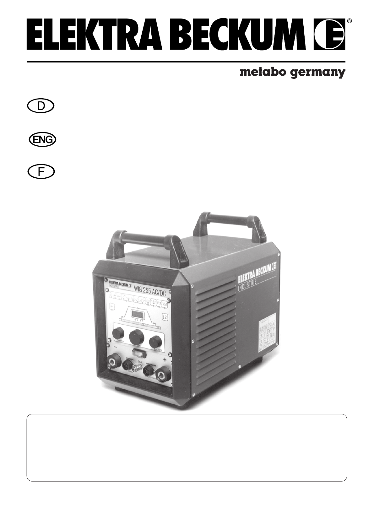
Betriebsanleitung WIG 255 AC/DC
Operating Instructions TIG 255 AC/DC
Instructions d'utilisation TIG 255 AC/DC
Read these instructions carefully before commissioning and operating this TIG Welding Machine
Elektra Beckum reserves the right to change specifications and design without prior notice and without incurring
48/02 - de, en, fr - 2.0
Achtung!
Bitte lesen Sie die Betriebsanleitung vor der Installation und Inbetriebnahme des
WIG 255 AC/DC Schweißgerätes aufmerksam durch.
Note
Attention !
Veuillez lire attentivement les instructions d'utilisation avant de mettre en service
l'appareil de soudage TIG 255 AC/DC.
Technische Änderungen vorbehalten!
obligation of any kind. Equipment referred to as available or optional may be at extra cost.
Sous réserve de modifications techniques !
Art.-Nr. 115 118 9942
Page 2

Inhalt:
1.0 Technische Daten 5.0 Gebrauchshinweise
2.0 Anwendungsbereiche 6.0 Überlastung/Netzfehler
3.0 Inbetriebnahme 7.0 Gefahrenhinweise
4.0 Funktionsbeschreibung 8.0 Störungsbeseitigung
9.0 Stromlaufplan
1.0 Technische Daten
Netzspannung : 3~400 V
Netzfrequenz : 50-60 Hz
Leerlaufspannung : 57 V
Stromeinstellbereich : 5-250 A AC/DC, Elektrode
Eingangsleistung : 6,6 KVA WIG AC/DC, 9,9 KVA Elektrode
Arbeitsspannung : 10,2-20 V WIG AC/DC
20,2-30 V Elektrode
Eingangs-Höchststrom : 16 A
Netzsicherung : 16 A
Einschaltdauer (ED) : 250 A - 75 %
220 A - 100 %
Betriebsarten : 2-Takt/4-Takt/Elektrode
Lichtbogenzündung : Umschaltbar, Hochfrequenz oder Kontaktzündung
Wechselstrom : Rechteckförmig, 50-200 Hz
Balance einstellbar - 70% bis 30%
Pulsbetrieb : Stufenlos einstellbar
Pulszeit 0,1-2 s
Pulspause 0,1-2 s
Grundstrom 0-100 %
Hotstart : Stufenlos einstellbar 0-100 %
Up/Down-Slope : Stufenlos einstellbar 0,1-10 s
(Stromanstieg/-absenkung)
Gasnachströmzeit : Stufenlos einstellbar 0,1-20 s
Arbeitsbereiche : für Aluminium ab 0,5 mm
für Stahl ab 0,3 mm
Leistungsfaktor cos ϕ : 0,99
Schutzart : IP 23 S
Kühlart : F
Isolierstoff-Klasse : F
Temperaturbereich : Betrieb -10 - +40°C
Lagerung -20 - +70°C
Maße : 530x330x380
Gewicht : ca 33 kg
2.0 Anwendungsbereiche
Das WIG 255 AC/DC-Gerät ist als praxisgerechtes, baustellensicheres Gerät konzipiert. Mit ihm lassen sich alle
Metalle verschweißen. Besonderen Wert wurde auch auf das Lichtbogenverhalten im Elektrodenschweißbetrieb
gelegt (Fallnahtsicherheit).
Weitere Anwendungsmöglichkeiten sind:
- WIG-Schweißen im DC-Bereich im 2-Takt oder 4-Takt mit und ohne HF-Zündung
- WIG-Schweißen im AC-Bereich im 2-Takt oder 4-Takt mit HF-Zündung
Wechselstrom im absoluten Rechteckstrom (Square Wave).
- Pulsschweißen im AC- und DC-Bereich
- Stabelektrodenschweißen mit einstellbarem Hotstart
- Einsatz aller Schweißverfahren mit Hand- oder Fußfernregler. Beim WIG-Schweißen ist eine Zündung über
den Hand- oder Fußfernregler möglich.
- Einsetzbar in Umgebungen mit erhöhter elektrischer Gefährdung (z.B. in Kesseln und Behältern). Somit trägt
die Anlage das "S"-Zeichen (früher "K"-Zeichen).
- Einsatz im stationären Einsatz, sowie auf Baustellen und auch in Zusammenarbeit mit Stromerzeugern.
Page 3
Produkthaftung/Garantie:
Nicht aufgeführte Arbeiten und Einsatzmöglichkeiten bedürfen der schriftlichen Genehmigung der Firma
Elektra Beckum AG , Postfach 1352, D-49703 Meppen.
Jeder Maschine und dem Maschinenzubehör ist eine Garantiekarte beigefügt. Zur Wahrung Ihres
Garantieanspruches und im Interesse der Produktsicherheit achten Sie bitte darauf, daß die Garantiekarte sofort
beim Verkauf ausgefüllt und die Antwortkarte ans Werk geschickt wird.
Bitte melden Sie sich mit Garantieansprüchen bei Ihrem Fachhändler.
Garantiearbeiten werden grundsätzlich von autorisierten Servicestellen durchgeführt.
Auch außerhalb der Garantiezeit dürfen Reparaturen nur durch autorisierte Servicestellen durchgeführt werden.
Bitte Reparaturrechnungen verwahren!
3.0 Inbetriebnahme
Achtung: Die Geräte werden im Werk mit großer Sorgfalt gebaut und eingehend geprüft. Alle Schweißgeräte
durchlaufen eine computergesteuerte Prüfeinrichtung und bekommen vom Werk ein Prüfzertifikat beigelegt.
Bitte überprüfen Sie die Maschine unverzüglich nach dem Auspacken auf eventuelle Transportschäden. Im Falle
eines Defektes informieren Sie bitte unverzüglich Ihren Lieferanten. Achten Sie beim Anschluß des Gerätes
unbedingt auf die richtige Anschlußspannung (entsprechend dem Typenschild). Es werden die Anschlüsse L1,
L2, L3 und PE benötigt. Schließen Sie das Gerät nur an eine ordnungsgemäße installierte 5-polige CEESteckdose an. Als Schutzgas im WIG-Schweißbetrieb wird ausschließlich Argon (Helium) verwendet. Der
Gasanschluß darf nur über eine geeignete Druckmindereinrichtung (max. 10 bar) erfolgen. Die Massezange muß
mit einem Anschlußkabel mit mindestens 25 mm2 ausgerüstet sein. Nach der Betätigung des Hauptschalters [1]
ist das Gerät betriebsbereit.
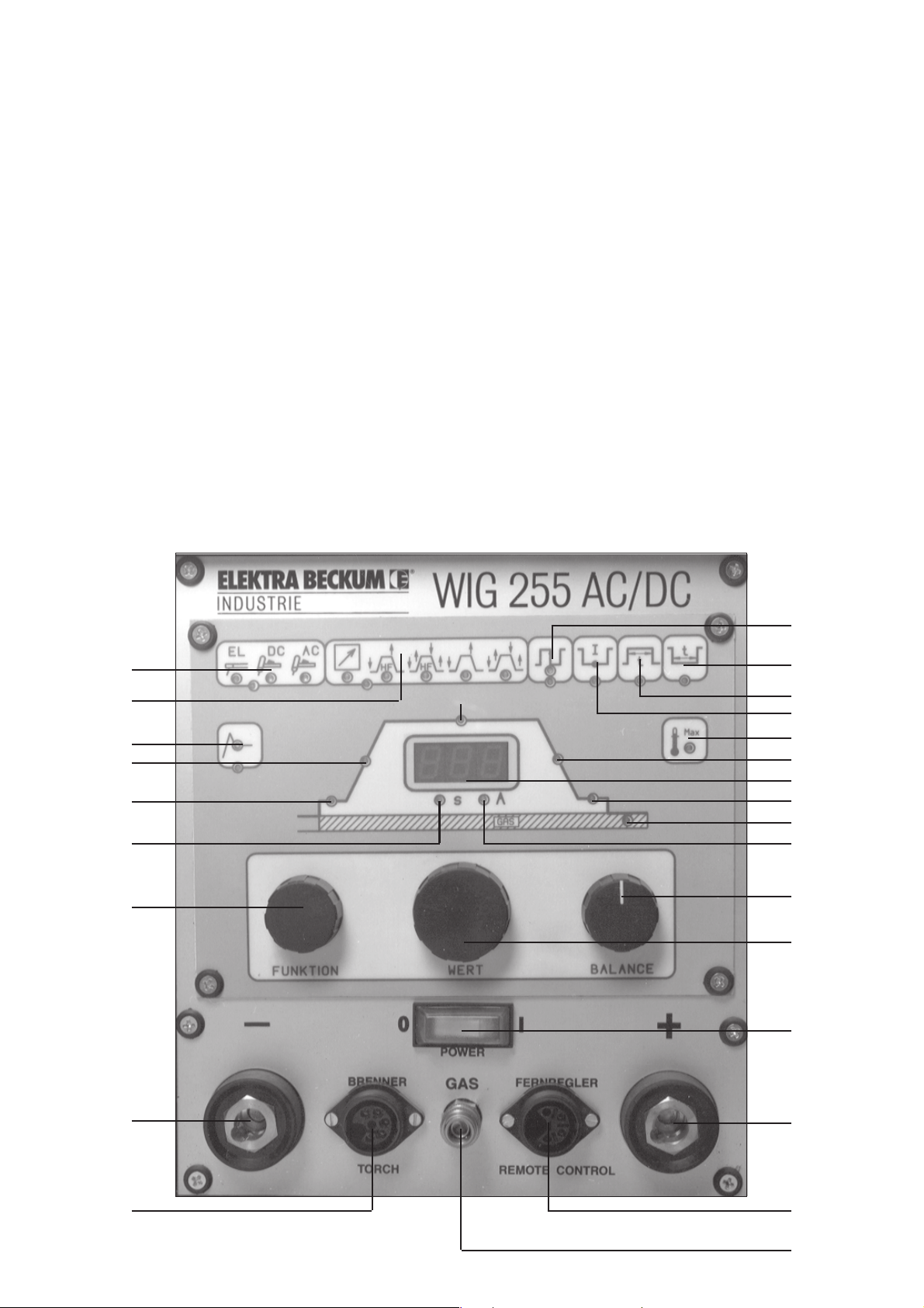
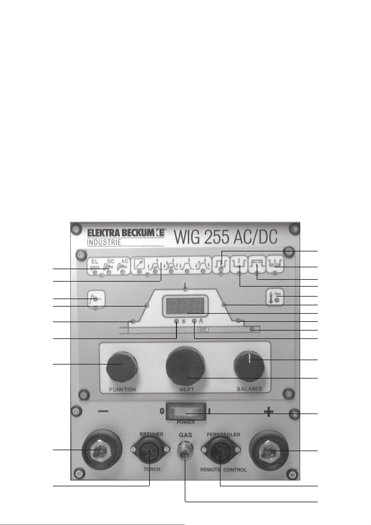
4.0 Funktionsbeschreibung
13
14
12
20
19
25
7
21
15
18
17
16
11
22
10
23
24
26
9
8
1
6
5
2
3
4
Page 4

4.1 Bedienungselemente
1 Netzschalter EIN/AUS
2 Anschluß: 1. Bei WIG-Betrieb: Massezange
2. Bei Elektrodenhandschweißen: (+) Pol
3 Anschluß für Hand- oder Fußfernregler
4 Anschluß für Schutzgas
5 Anschluß für Brennerschaltung
6 Anschluß: 1. Bei WIG-Betrieb: Brenneranschluß
2. Bei Elektrodenhandschweißen: (-) Pol
7 Drehpotentiometer für Funktionswahl
8 Drehpotentiometer für Werteinstellung
9 Drehpotentiometer für die Lichtbogeneinstellung
Bei der Funktion WIG-AC Schweißen - Einstellung der Balance für die Ausregelung des Gleichrichtereffektes
10 Digitalanzeige
11 Überlast-Netzfehleranzeige
12 Bei Elektrodenhandschweißen: Hotstart, Stromaddition 0 - 100 %
13 Schweißarten-Anzeige: - Elektrodenschweißbetrieb
- WIG-DC-Schweißbetrieb
- WIG-AC-Schweißbetrieb
14 Betriebsarten-Anzeige: - Fernbedienung
- 2-Takt-Schweißen mit Hochfrequenz
- 4-Takt-Schweißen mit Hochfrequenz
- 2-Takt-Schweißen ohne Hochfrequenz
- 4-Takt-Schweißen ohne Hochfrequenz
15 Pulsen EIN/AUS
16 Pulsgrundstrom-Einstellung
17 Pulszeit-Einstellung von 0,1 - 5 Sek.
18 Pulspausen-Einstellung von 0,1 - 5 Sek.
19 LED-Grün: Funktion Startstrom - Einstellung 5 - 250 Ampere
20 LED-Grün: Funktion Anstiegszeit - Einstellung 0,1 - 10 Sek.
21 LED-Grün: Funktion Schweißstrom - Einstellung 5 - 250 Ampere
22 LED-Grün: Funktion Absenkzeit - Einstellung 0,1 - 10 Sek.
23 LED-Grün: Funktion Endstrom - Einstellung 5 - 250 Ampere
24 LED-Grün: Funktion Gasnachströmzeit - Einstellung 0 - 20 Sek.
25 LED-Rot für Zeitanzeige im Digitalfeld
26 LED-Rot für Ampereanzeige im Digitalfeld
Die Funktionsbeschreibung für die einzelnen Bedienungselemente folgt unter Punkt 4.2 und 4.3.
4.1.1Legende
- 1 Potentiometer "Funktion" (7) aktiviert bei der Bedienung alle einzustellenden Funktionen die sichtbar sind
mit dem Aufleuchten der grünen LED-Diode.
- 2 Potentiometer "Wert" (8) kann innerhalb einer gewählten Funktion ein einzustellender Wert eingestellt
werden und ist mit dem Aufleuchten einer roten LED-Diode gekennzeichnet.
- 3 Potentiometer "Balance" (9) separate Einstellung der Ausregelung des Gleichrichtereffektes bei der
Funktion WIG-AC (Aluminiumschweißung).
Page 5
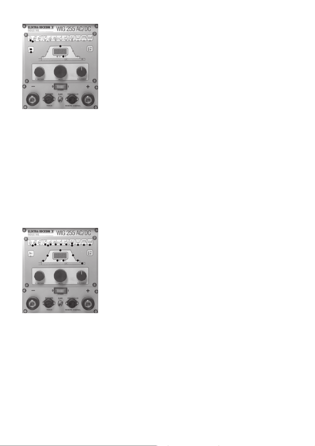
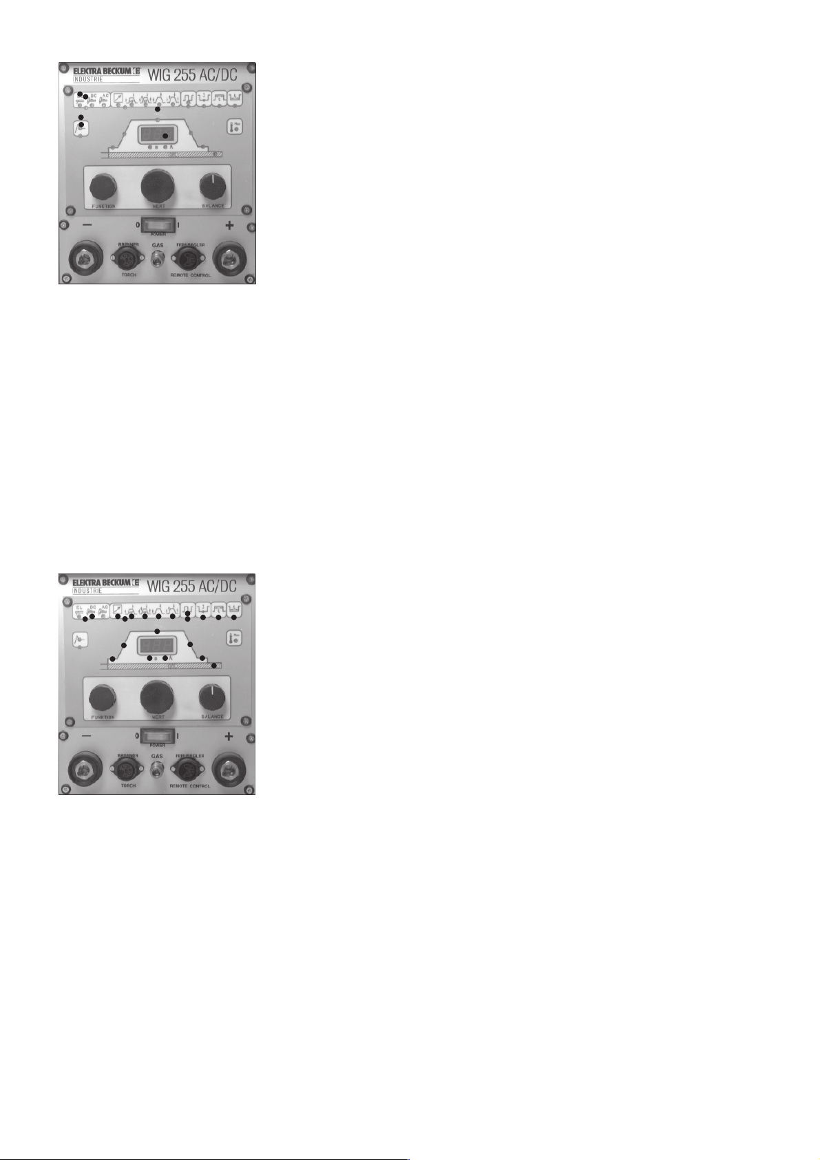
4.2 Funktionsbeschreibung Elektrodenhandschweißen
- Gerät wir am Netzschalter (1) eingeschaltet.
- Drehpotentiometer "Funktion" Drehung nach links bis LED-Grün des Gruppen-
bildes "Schweißarten-Anzeige" (13) leuchtet. Drehpotentiometer "Wert" Dre-
hung auf Elektrodenfunktion, LED-Rot leuchtet und zeigt die Aktivierung an.
- Drehpotentiometer "Funktion" Drehung nach links bis LED-Grün des Funktions-
bildes "Hotstart" (12) leuchtet. Drehpotentiometer "Wert" Einstellung des Hotstart von 0 - 100 % (prozentuale Stromaddition zum eingestellten Schweißstrom), Prozentangabe ist im Digitalfeld (19) sichtbar. LED-Rot im Funktionsbild
"Hotstart" leuchtet und zeigt die Aktivierung an.
- Drehpotentiometer "Funktion" Drehung nach rechts auf Funktion Schweißstrom (21) oder ca. 5 Sek. warten, dann springt die Funktion automatisch in die
Einstellung Schweißstrom (21). Drehpotentiometer "Wert", Einstellung des
Schweißstromes, LED-Rot (26) zeigt die Einstellung in Ampere an. In dieser
Funktion sind die Einstellungen für das WIG-Schweißen außer Funktion.
Der Anschluß des Elektrodenhalters und der Massezange erfolgt an den Anschlüssen 2 und 6. Es können alle Arten
von Elektroden verschweißt werden (an Pluspol und Minuspol zu verschweißenden Elektroden).
Zusätzlich hat dieses Gerät einen stufenlos einstellbaren Hotstart. Die jeweilige Einstellung ist der prozentuale
Stromimpuls. Die Dauer des Stromimpulses beträgt 0,2 - 0,4 Sek.
Vorteile des Hotstarts sind: - Sehr gutes Zündverhalten bei schwerzündenden Elektroden.
- Kleben der Elektroden am Material wird weitgehend verhindert (Anti-Stick-Regelung).
- Durch den Stromimpuls wird der Grundwerkstoff in der Tiefe aufgeschmolzen und
dadurch Verhinderung von Bindefehlern.
Das WIG 255 AC/DC weist hervorragende Eigenschaften bei Fallnähten auf, da ein ruhiger, stabil brennender
Lichtbogen ein Herunterrutschen der Schlacke verhindert.
Beim Einschalten des Gerätes erscheinen die zuletzt eingestellten Parameter.
4.3 Funktionsbeschreibung WIG
Das WIG 255 AC/DC ist geeignet für das Gleichstromschweißen von Stahl, Edelstahl und Bundmetallen außer
Aluminium.
Bei der Wechselstromschweißung können Aluminium und Aluminiumlegierungen verschweißt werden.
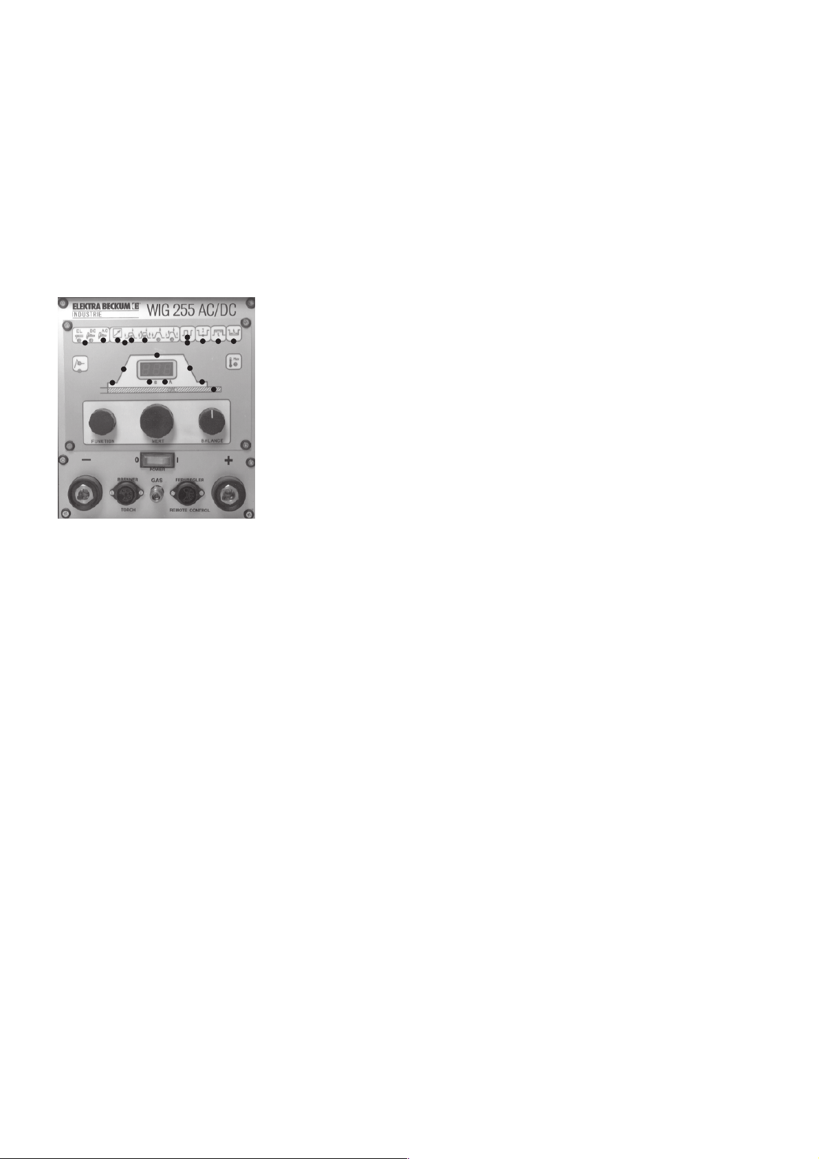
4.3.1WIG-DC-Schweißen
- Gerät wir am Netzschalter (1) eingeschaltet.
- Drehpotentiometer "Funktion" Drehung nach links bis LED-Grün des Gruppen-
bildes "Schweißarten-Anzeige" (13) leuchtet. Drehpotentiometer "Wert" Dre-
hung auf WIG-DC, LED-Rot leuchtet und zeigt die Aktivierung an.
-Drehpotentiometer "Funktion" Drehung nach rechts bis LED-Grün des Funktions-
bildes "Betriebsarten-Anzeige" (14) leuchtet. Drehpotentiometer "Wert"
Drehung auf die Betriebsarten:
- Fernbedienung-Fernstart (Beschreibung Pkt. 4.3.6)
- 2-Takt-Steuerung mit HF (Beschreibung Pkt. 4.3.3)
- 4-Takt Steuerung mit HF (Beschreibung Pkt. 4.3.4)
- 2-Takt-Steuerung ohne HF (Beschreibung Pkt. 4.3.3)
- 4-Takt-Steuerung ohne HF (Beschreibung Pkt. 4.3.4), LED-Rot leuchtet und
zeigt den aktiven Teil an.
- Drehpotentiometer "Funktion" Drehung auf Startstrom (19), LED-Grün leuchtet. Drehpotentiometer "Wert"
Einstellung des Startstromes von 5 - 250 A. Digitalfeld (10) zeigt den eingestellten Wert in Ampere an, LED-Rot (26)
ist aktiviert.
- Drehpotentiometer "Funktion" Drehung auf Anstiegszeit (20), LED-Grün leuchtet. Drehpotentiometer "Wert"
Einstellung der Anstiegszeit von 0,1 - 10 Sek. Digitalfeld (10) zeigt den eingestellten Wert in Sekunden an, LED-Rot
(25) ist aktiviert.
- Drehpotentiometer "Funktion" Drehung auf Schweißstrom (21), LED-Grün leuchtet. Drehpotentiometer "Wert"
Einstellung des Schweißstromes von 5 - 250 A. Digitalfeld (10) zeigt den eingestellten Wert in Ampere an, LED-Rot
(26) ist aktiviert.
- Drehpotentiometer "Funktion" Drehung auf Absenkzeit (22), LED-Grün leuchtet. Drehpotentiometer "Wert"
Einstellung der Absenkzeit von 0,1 - 10 Sek. Digitalfeld (10) zeigt den eingestellten Wert in Sekunden an, LED-Rot
(25) ist aktiviert.
- Drehpotentiometer "Funktion" Drehung auf Endstrom (23), LED-Grün leuchtet. Drehpotentiometer "Wert" Einstel-
lung des Endstromes von 5 - 250 A. Digitalfeld (10) zeigt den eingestellten Wert in Ampere an, LED-Rot (26) ist
aktiviert.
- Drehpotentiometer "Funktion" Drehung auf Gasnachströmzeit (24), LED-Grün leuchtet. Drehpotentiometer "Wert"
Einstellung der Gasnachströmzeit von 0 - 20 Sek. Digitalfeld (10) zeigt den eingestellten Wert in Sekunden an, LEDRot (25) ist aktiviert.
Page 6
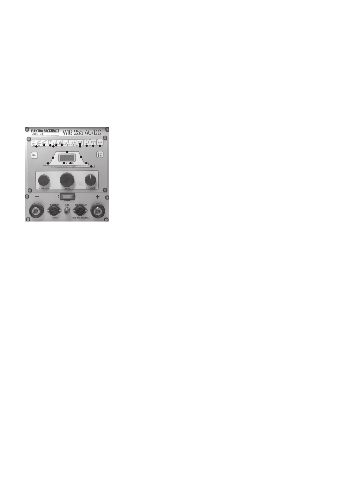
Wenn für das WIG-DC-Schweißen zusätzlich die Pulsfunktion aktiviert werden soll, folgender Ablauf (Beschreibung des
Pulsschweißen 4.3.8):
- Drehpotentiometer "Funktion" Drehung nach rechts bis LED-Grün des Bildes "Pulsen" (15) erleuchtet. Drehpotentiometer "Wert" Drehung, LED-Rot erleuchtet und die Pulsfunktion ist aktiviert.
- Drehpotentiometer "Funktion" Drehung nach rechts bis LED-Grün des Bildes "Pulsgrundstrom-Einstellung" (16)
erleuchtet. Drehpotentiometer "Wert" Einstellung des Pulsgrundstromes von 5 - 250 A. Digitalfeld (10) zeigt den
eingestellten Wert in Ampere an, LED-Rot (26) ist aktiviert.
- Drehpotentiometer "Funktion" Drehung nach rechts bis LED-Grün des Bildes "Pulszeit-Einstellung" (17) erleuchtet.
Drehpotentiometer "Wert" Einstellung der Pulszeit von 0,1 - 5 Sek. Digitalfeld (10) zeigt den eingestellten Wert in
Sekunden an, LED-Rot (25) ist aktiviert.
- Drehpotentiometer "Funktion" Drehung nach rechts bis LED-Grün des Bildes "Pulspausen-Einstellung" (18)
erleuchtet. Drehpotentiometer "Wert" Einstellung der Pulspause von 0,1 - 5 Sek. Digitalfeld (10) zeigt den
eingestellten Wert in Sekunden an, LED-Rot (25) ist aktiviert.
4.3.2WIG-AC-Schweißen
- Gerät wird am Netzschalter (1) eingeschaltet.
- Drehpotentiometer "Funktion" Drehung nach links bis LED-Grün des Gruppen-
bildes "Schweißarten-Anzeige" (13) leuchtet. Drehpotentiometer "Wert" Dre-
hung auf WIG-AC, LED-Rot leuchtet und zeigt die Aktivierung an.
- Drehpotentiometer "Funktion" Drehung nach rechts bis LED-Grün des Gruppenbildes "Betriebsarten-Anzeige" (14) leuchtet. Drehpotentiometer "Wert"
Drehung auf die Betriebsarten:
- Fernbedienung-Fernstart (Beschreibung Pkt. 4.3.6)
- 2-Takt-Steuerung mit HF (Beschreibung Pkt. 4.3.3)
- 4-Takt Steuerung mit HF (Beschreibung Pkt. 4.3.4) LED-Rot leuchtet und zeigt
den aktiven Teil an.
- Drehpotentiometer "Funktion" Drehung auf Startstrom (19), LED-Grün leuchtet. Drehpotentiometer "Wert" Einstellung des Startstromes von 5 - 250 A.
Digitalfeld (10) zeigt den eingestellten Wert in Ampere an, LED-Rot (26) ist
aktiviert.
- Drehpotentiometer "Funktion" Drehung auf Anstiegszeit (20), LED-Grün leuchtet. Drehpotentiometer "Wert"
Einstellung der Anstiegszeit von 0,1 - 10 Sek. Digitalfeld (10) zeigt den eingestellten Wert in Sekunden an, LED-Rot
(25) ist aktiviert.
- Drehpotentiometer "Funktion" Drehung auf Schweißstrom (21), LED-Grün leuchtet. Drehpotentiometer "Wert"
Einstellung des Schweißstromes von 5 - 250 A. Digitalfeld (10) zeigt den eingestellten Wert in Ampere an, LED-Rot
(26) ist aktiviert.
- Drehpotentiometer "Funktion" Drehung auf Absenkzeit (22), LED-Grün leuchtet. Drehpotentiometer "Wert"
Einstellung der Absenkzeit von 0,1 - 10 Sek. Digitalfeld (10) zeigt den eingestellten Wert in Sekunden an, LED-Rot
(25) ist aktiviert.
- Drehpotentiometer "Funktion" Drehung auf Endstrom (23), LED-Grün leuchtet. Drehpotentiometer "Wert" Einstel-
lung des Endstromes von 5 - 250 A. Digitalfeld (10) zeigt den eingestellten Wert in Ampere an, LED-Rot (26) ist
aktiviert.
- Drehpotentiometer "Funktion" Drehung auf Gasnachströmzeit (24), LED-Grün leuchtet. Drehpotentiometer "Wert"
Einstellung der Gasnachströmzeit von 0 - 20 Sek. Digitalfeld (10) zeigt den eingestellten Wert in Sekunden an, LED-
Rot (25) ist aktiviert.
Wenn für das WIG-AC-Schweißen zusätzlich die Pulsfunktion aktiviert werden soll, folgender Ablauf (Beschreibung des
Pulsschweißen 4.3.8):
- Drehpotentiometer "Funktion" Drehung nach rechts bis LED-Grün des Bildes "Pulsen" (15) erleuchtet. Dreh-
potentiometer "Wert" Drehung, LED-Rot erleuchtet und die Pulsfunktion ist aktiviert.
- Drehpotentiometer "Funktion" Drehung nach rechts bis LED-Grün des Bildes "Pulsgrundstrom-Einstellung" (16)
erleuchtet. Drehpotentiometer "Wert" Einstellung des Pulsgrundstromes von 5 - 250 A. Digitalfeld (10) zeigt den
eingestellten Wert in Ampere an, LED-Rot (26) ist aktiviert.
- Drehpotentiometer "Funktion" Drehung nach rechts bis LED-Grün des Bildes "Pulszeit-Einstellung" (17) erleuchtet.
Drehpotentiometer "Wert" Einstellung der Pulszeit von 0,1 - 5 Sek. Digitalfeld (10) zeigt den eingestellten Wert in
Sekunden an, LED-Rot (25) ist aktiviert.
- Drehpotentiometer "Funktion" Drehung nach rechts bis LED-Grün des Bildes "Pulspausen-Einstellung" (18)
erleuchtet. Drehpotentiometer "Wert" Einstellung der Pulspause von 0,1 - 5 Sek. Digitalfeld (10) zeigt den
eingestellten Wert in Sekunden an, LED-Rot (25) ist aktiviert.
- Drehpotentiometer "Balance", Beschreibung unter Pkt. 4.3.7.
In der Funktion WIG-AC-Schweißen besitzt die Anlage eine automatische Frequenzanpassung von 50 - 200 Hz.
Vorteil ist, bei Schweißung von geringen Amperezahlen (ca. 50 A) arbeitet die Anlage mit 200 Hz. Dadurch sehr guter
Reinigungseffekt bei der Dünnblechschweißung ab 0,5 mm Aluminium bei geringer Energiezufuhr.
Bei Schweißung von hohen Amperezahlen (ca. 250 A) arbeitet die Anlage mit 50 Hz. Durch die hohe Energiezuführung
ist ein ausreichender Reinigungseffekt garantiert. In den beschriebenen Amperebereich paßt sich die Frequenz immer
optimal an.
Page 7
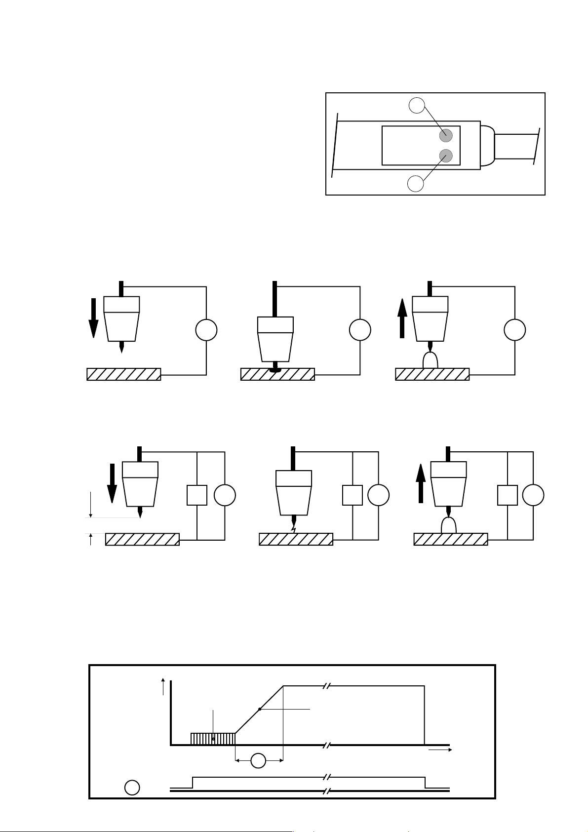
4.3.3Anschluß
20
21
Brenner - Torch
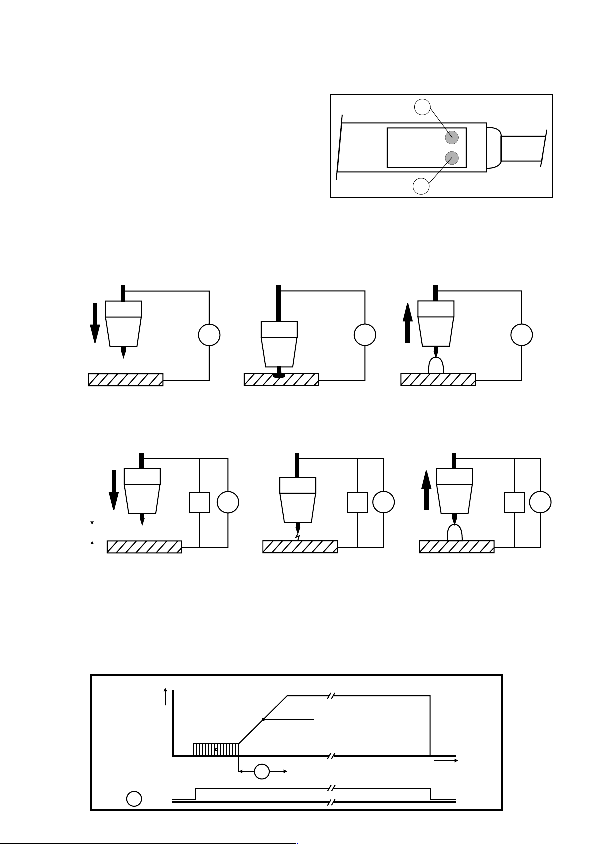
Das Hauptstromkabel des WIG-Brenners wird an (6) und die Steuerung des WIG-Brenners an (5) angeschlossen. Die Gaszufuhr erfolgt über die Schnellkupplung (4). Die Verbindung zum Schweißtisch bzw. Werkstück
erfolgt mit dem Anschluß (2). Zusätzlich kann über den Anschluß (3) ein Hand- oder Fußfernregler angeschlossen werden. Der vorgewählte Strom läßt sich auch mit Hilfe eines im Brenner eingebauten Potentiometers
verstellen.
Bild 1
Achtung: Bei gleichzeitigem Anschluß eines Hand- oder Fußfernreglers und eines Brenners mit eingebautem
Fernreglerpotentiometer beeinflussen sich diese beiden Regler gegenseitig. Also stets nur einen Regler anschließen.
4.3.4 Zünden des Lichtbogens
4.3.4.1 Zünden durch Berühren des Werkstückes mit der Elektrode
G
Annäherung Kurzschluß Entstehung des
ans Werkstück und Erwärmung Lichtbogens
4.3.4.2 Berührungsloses Zünden durch Hochspannungsimpuls
= 2 mm
Annäherung Zünden des Entstehung des
ans Werkstück Hilfslichtbogens durch Lichtbogens
G
I
Hochspannungsimpulse
G G
G G
I I
4.3.5 2-Takt Betrieb
Bei der Betätigung des Brennertasters Rot (Bild 1: 20) wird der Schweißvorgang gestartet. Nach erfolgter Zündung
(entweder HF- oder Kontaktzündung) läuft der Schweißstrom vom Startstrom auf den eingestellten Schweißstrom in
einer eingestellten Anstiegszeit.
Beim Loslassen der Taste (Bild 1: 20) erlischt der Lichtbogen sofort.
2-Takt
2-step
mode
Brennerschalter
Trigger Switch
20
I
Zündung
Ignition
Stromanstieg
Up-slope
t
10
Page 8
4.3.6 4-Takt Betrieb
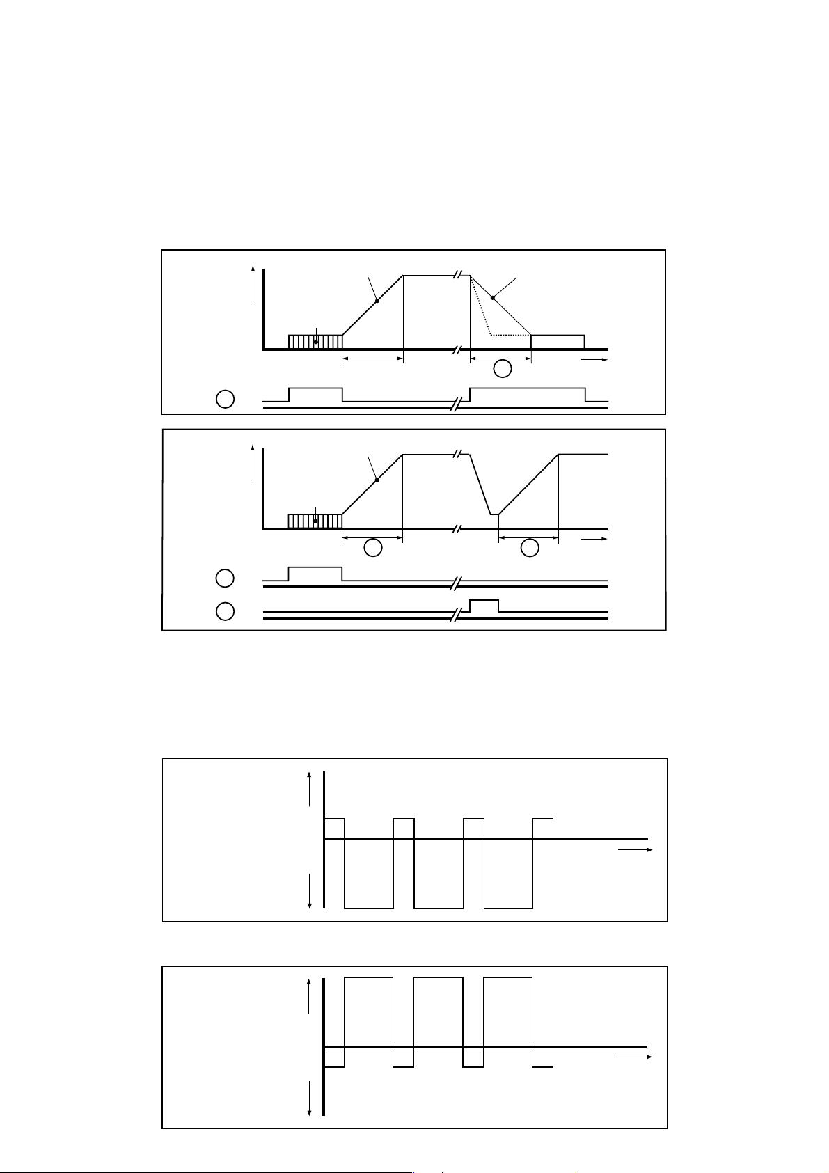
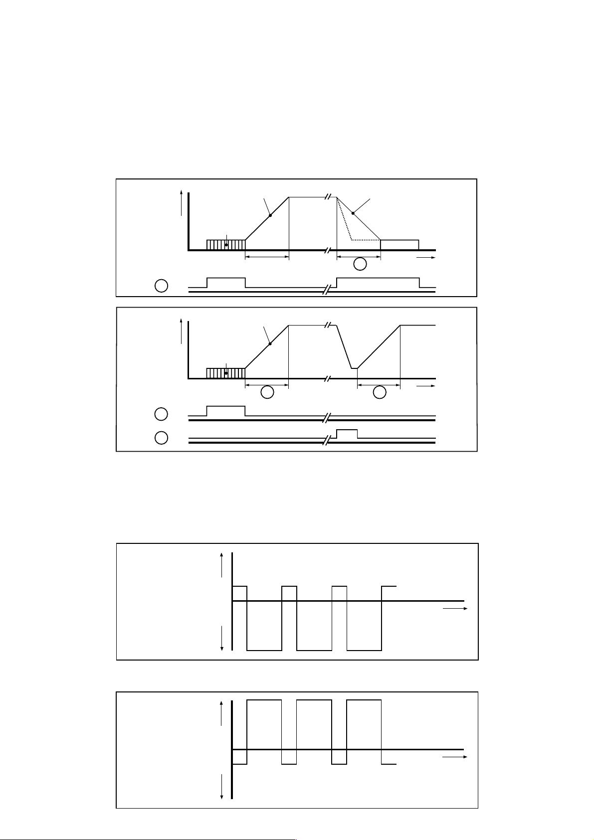
Bei der Betätigung des Brennertasters Rot (Bild 1: 20) wird der Schweißvorgang gestartet (Zündung durch HF- oder
Kontaktzündung). Solange der Brennertaster (Bild 1: 20) gedrückt wird, brennt der LB mit seinem Startstrom. Der
Startstrom kann wie bei 2-Takt Betrieb eingestellt werden, mindestens jedoch 5 A (Suchlichtbogen). Nach dem
Loslassen des Brennertasters Rot Bild (1: 20) läuft der Lichtbogen-Strom durch Einstellung der Anstiegszeit (10) von
0,1 - 10s auf den eingestellten Schweißstrom. Bei erneuter Betätigung der Brennertaster Rot (Bild 1: 20) sinkt der
Lichtbogen-Strom innerhalb der Absenkzeit von 0,1 - 10 s auf den Endstrom ab (Endkraterfüllung). Nach dem Loslassen
des Tasters Rot (Bild 1: 20) erlischt der Lichtbogen.
Durch entsprechende Einstellung der Anstiegs- und Absenkzeit kann mit Hilfe des zweiten Tasters im Brennerhandgriff
Grün (Bild 1: 21) der Lichtbogen-Strom jederzeit auf den Endstrom reduziert werden, ohne daß hierdurch der
Schweißvorgang unterbrochen wird. Nach dem Loslassen des Tasters Grün (Bild 1: 21) steigt der Lichtbogen-Strom
wieder auf seinen voreingestellten Wert an.
I
4-Takt
4-step
mode
Brennerschalter
Stromanstieg
Up-slope
Zündung
Ignition
Stromabsenkzeit
Down-slope
11
t
Trigger Switch
20
Stromanstieg
I
Up-slope
Zündung
Ignition
Brennerschalter
10
10
t
Trigger Switch
20
21
4.3.7 Balancesteuerung
Beim Wolfram-Inertgasschweißen von Aluminium mit Wechselstrom tritt ein Gleichrichtereffekt ein, das heißt, die
Halbwellen des Wechselstroms sind unterschiedlich stark ausgebildet. Durch die Balancesteuerung (9) ist eine
Regelung des Gleichrichtereffekts von +30 % bis -70 % möglich.
Die negative Halbwelle ist stärker ausgebildet (größeren Einbrand/kl. Reinigung).
+
Lichtbogen
strom
0
Arc current
–
Die positive Halbwelle ist stärker ausgebildet (wenig Einbrand, gr. Reinigung).
Achtung: Gefahr der Wärmeüberlastung der Elektrode.
+
Lichtbogen
strom
0
Arc current
–
t
t
Page 9
4.3.8 Impulsschweißen
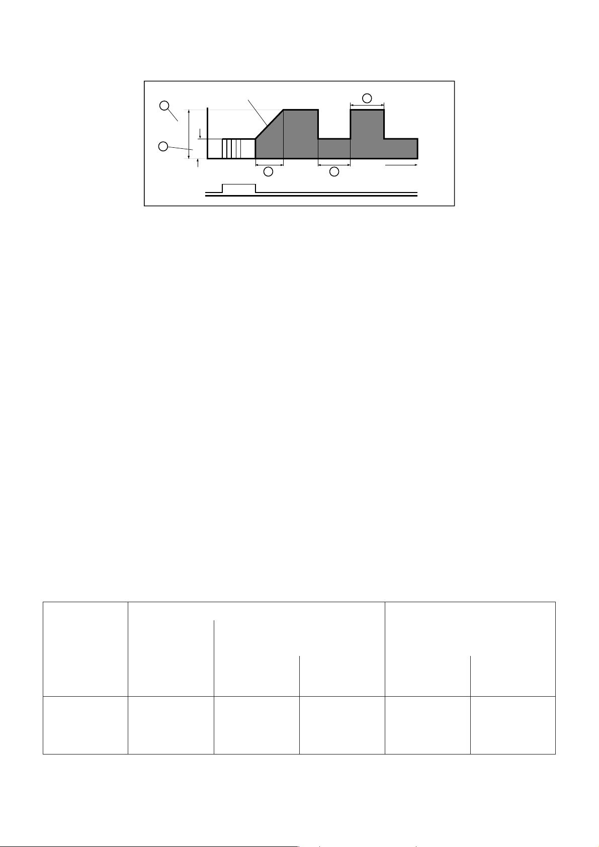
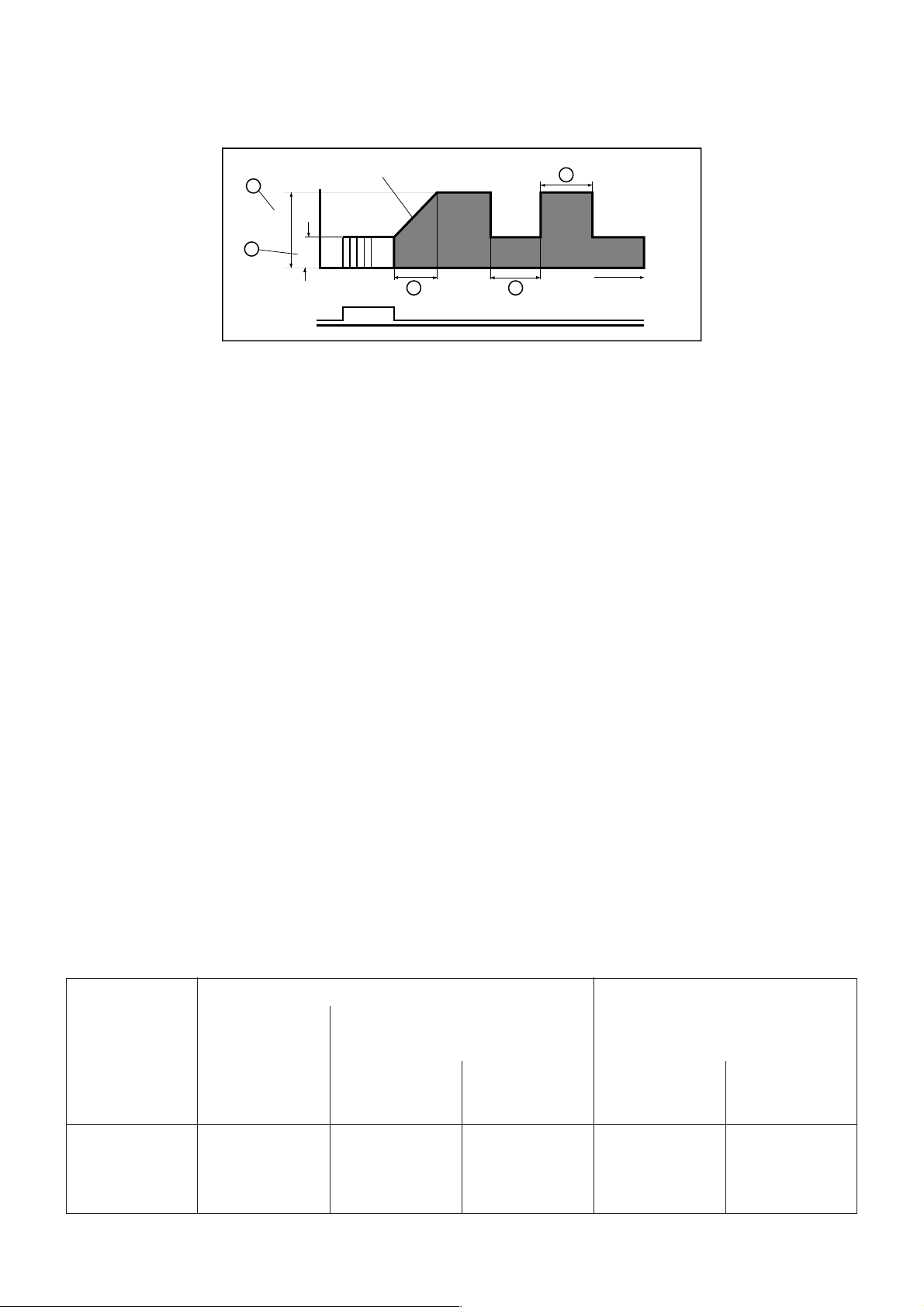
Beim Pulsschweißen brennt ein Lichtbogen mit stufenlos einstellbarem Grundstrom (Funktion 16 von 5 - 250 A).
Der Pulsstrom wird über die Funktion 16 eingestellt.
Pulszeit (17) und Pulspause (18) sind stufenlos von 0,1 - 5 s einstellbar.
Stromanstieg
21
Ip
Up-slope
Pulsdauer - Pulse time
17
19
Brennerschalter
Trigger Switch
Ig
20 18
Pulspause - Pulse dwell time
t
Vorteile:
- Schweißen von sehr dünnem Material
- geringe Einbringung von Streckenenergie beim Schweißen von hochleg. Stählen
- Schweißen von dickem mit dünnem Material
4.3.9 Funktion Fernstart
Bei der Funktion Fernstart kann am Anschluß (3) ein Hand- oder Fußfernregler angeschlossen werden. Für den
Anwender besteht jetzt bei dieser Funktion die Möglichkeit, daß vom Hand- oder Fußfernregler gestartet und geregelt
(zwischen eingestellten Startstrom und eingestellten maximalen Schweißstrom) werden kann.
Die Bedienungselemente auf dem WIG-Brenner sind somit außer Funktion.
Somit kann der Anwender präzise Schweißungen durchführen, ohne seine Hand am Brenner zwecks Steuerung zu
bewegen.
Bei den Funktionen 2- oder 4-Takt-Steuerung mit oder ohne HF-Zündung kann ein Hand- oder Fußfernregler ebenfalls
angeschlossen werden, aber ein Starten muß dann von den Brennertaster (Bild 1: 20) erfolgen.
5.0 Gebrauchshinweise
Um ein sicheres Zünden und einwandfreie Schweißergebnisse zu erzielen, sollten folgende Punkte beachtet werden:
5.1 Elektrodentypen
Für das WIG-Schweißen mit Gleichstrom sollten nur thorierte Elektroden verwendet werden:
z.B. WT 20 1,8 - 2,2 % Thoriumoxyd, Kennfarbe: Rot
WT 30 2,8 - 3,2 % Thoriumoxyd, Kennfarbe: Violett
Für das WIG-Schweißen im Wechselstrom sollten nur reine Wolfram-Elektroden verwendet werden:
z.B. W-Wolframelektrode, Kennfarbe: Grün
5.2 Elektrodendurchmesser
Der Elektrodendurchmesser muß dem LB-Strom angepasst sein.
Richtwerte: unter 80 A : Durchmesser 1,0 mm
70 bis 140 A : Durchmesser 1,6 mm
130 bis 250 A : Durchmesser 2,5 mm
bei AC >220 A : Durchmesser 3,2 mm
5.2.1 Strombelastbarkeiten von WIG-Elektroden
Durchmesser Schweißstromstärke bei Gasdüse
Gleichstrom Wechselstrom mit Filter(Elektrode am kondensator
Minuspol) (Elektrode am Minuspol)
mit 2% Reinwolfram mit 2% Größe DurchThorium
1)
mm A A A mm
1,0 ... 80 ... 30 30 ... 60 4 ... 5 6,5 ... 8
1,6 10 ... 140 30 ... 70 40 ... 100 4 ... 6 6,5 ... 9,5
2,4 20 ... 230 50 ... 110 70 ... 150 6 ... 8 9,5 ... 12,7
3,2 30 ... 310 100 ... 170 130 ... 200 7 ... 8 11,2 ... 12,7
1)
bei Reinwolframelektroden sind die oberen Werte um etwa 40% niedriger
2)
ohne Balance sind die Werte um etwa 50% höher
Merke: Wolframelektroden müssen frei von Schmutz, Öl und Fette sein. Sie müssen durch geeignete Aufbewahrung
vor Verunreinigungen geschützt werden.
2)
Thorium messer
Page 10
5.3 Anschliff
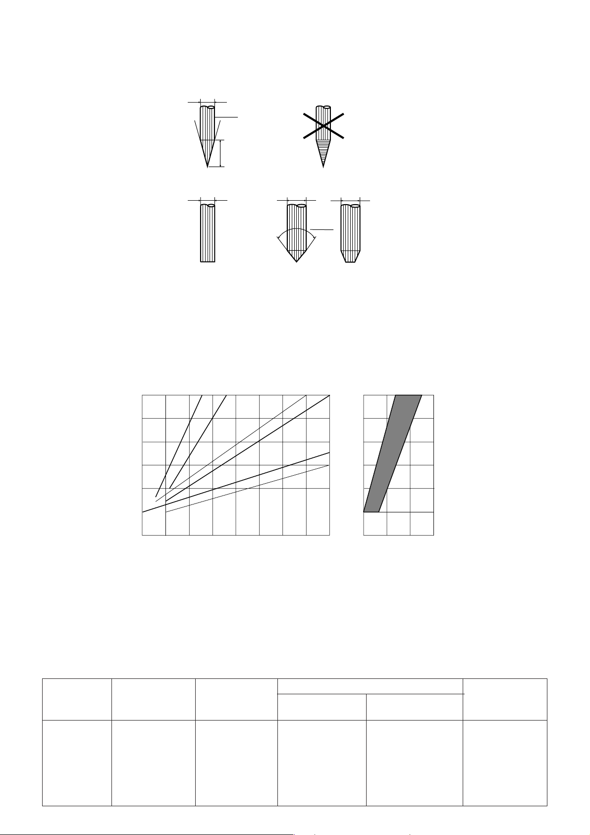
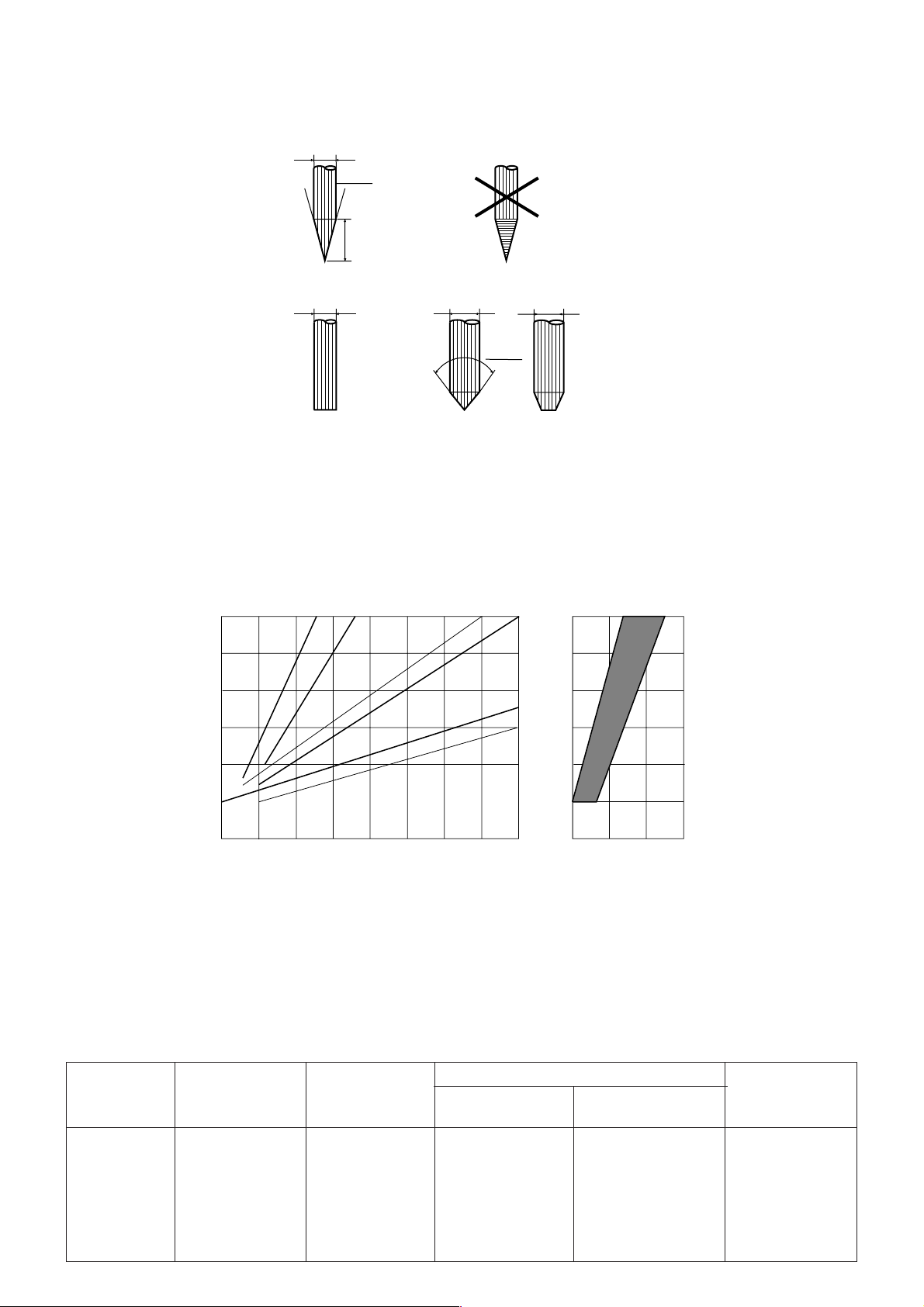
Das Anschleifen der Elektroden darf bei Gleichstrom nur in Längsrichtung erfolgen und bei Wechselstrom Elektrodendurchmesser 1,6 mm überhaupt nicht anschleifen und bei D >1,6 mm spitzwinklig und mit gebrochener Spitze. Beim
Schweißen mit Wechselstrom bildet sich automatisch an der Elektrode eine Tropfenform (Kalotte) heraus.
Schweißen mit Gleichstrom
(Minuspol an der Elektrode)
~30°
Die Elektrode wird in der Regel durch
Längsschleifen angespitzt. Schleifriefen
sind in Sonderfällen durch Polieren zu
entfernen.
Länge ~ 2 x D
D
D
Schweißen mit Wechselstrom
D
D
Bei größeren Durchmessern wird die
~ 90°
Elektrode angeschliffen. Beim Schweißen bildet sich an der Elektrodenspitze
eine Kugel (Kalotte).
>
D < 1.6 mm
D 1.6 mm
=
5.4 Gasmenge
Eine zu hohe Gasmenge kann die Zündeigenschaften verschlechtern. Der Schutzgasverbrauch und die damit
einzustellende Schutzgasmenge wird beeinflußt durch die Werkstückdicke und dem Grundwerkstoff.
Argonverbrauch l/min
10
9
Nickel
1
Aluminium, Magnesium, Kupfer
Stahl, Chrom-Nickel-Stahl
23
Werkstückdicke mm Gasdüsendurchmesser mm
4
5
67
8
7
6
5
4
85
10 15 20
5.5 Richtwerte für die Wahl der Schweißstromstärke beim WIG-Schweißen
Unlegierter und legierter Stahl
Gleichstrom; Minuspol an der Elektrode; Schweißposition w; Stumpfnaht
Blechdicke Fugenform Lagenzahl Durchmesser Stromstärke
Elektrode Schweißstab
mm mm mm A
1,0 II 1 1 oder 1,6 1,6 oder 2,0 30 ... 40
2,0 II 1 1,6 oder 2,4 1,6 oder 2,0 70 ... 80
3,0 II 1 oder 2 2,4 2,4 70 ... 90
4,0 II oder V 2 2,4 2,4 70 ... 130
5,0 V 3 2,4 oder 3,2 2,4 oder 3,0 75 ... 130
6,0 V 3 2,4 oder 3,2 2,4 oder 3,0 75 ... 130
Page 11

Aluminium
Wechselstrom; Minuspol an der Elektrode; Schweißposition w; Stumpfnaht
Blechdicke Fugenform Lagenzahl Durchmesser Stromstärke
Elektrode Schweißstab
mm mm mm A
1,0 II 1 1,6 oder 2,4 2,0 40 ... 50
2,0 II 1 1,6 oder 2,4 3,0 60 ... 80
3,0 II 1 2,4 3,0 110 ... 130
4,0 II 1 oder 2 2,4 oder 3,2 3,0 120 ... 150
5,0 V 1 oder 2 3,2 3,0 150 ... 200
Kupfer
Gleichstrom; Minuspol an der Elektrode; Schweißposition w; Stumpfnaht
Blechdicke Fugenform Lagenzahl Durchmesser Stromstärke
Elektrode Schweißstab
mm mm mm A
1,5 II 1 1,6 2,0 90 ... 100
1)
3,0
5,0
1)
II 1 3,2 3,0 150 ... 200
V24,0 4,0 180 ... 300
1)
= vorwärmen
Merke: Beim Schweißen in den Positionen s und ü ist die Schweißstromstärke um etwa 10 bis 20 % zu vermindern.
6.0 Überlastung / Netzfehler
6.1 Überlastung
Das WIG 255 AC/DC Gerät ist durch mehrere unabhängige Schutzeinrichtungen sicher gegen Überlastung geschützt.
Beim Überschreiten der zulässigen Einschaltdauer erfolgt automatisch eine Abschaltung des Gerätes. Dieser wird
durch die Kontrolleuchte (11) angezeigt (Die Leuchte blinkt).
Nach kurzer Zeit ist das Gerät wieder betriebsbereit.
Achtung:
Das Gerät in der Kühlphase nicht ausschalten, da sich sonst die Kühlzeit erheblich verlängert (Ventilator steht).
6.2 Netzfehler
Wird die Netzspannung um mehr als 10 % unterschritten, schaltet das Gerät automatisch ab, da anderenfalls zu hohe
Primärströme auftreten würden.
Dieser Fehler wird durch die Kontrolleuchte (11) angezeigt (Die Leuchte brennt konstant).
Durch Aus- und Wiedereinschalten des Gerätes wird diese Fehlermeldung zurückgesetzt.
7.0 Gefahrenhinweise
- Das Gerät darf nur für den vorgesehenen Anwendungsbereich eingesetzt werden
(WIG- und Elektrodenschweißen).
- Beim Einsatz des Gerätes unbedingt die Unfallverhütungsvorschriften beachten!
(DVV 26 Schweißen, Schneiden und verwandte Verfahren)
- Bei den Schweißarbeiten ist unbedingt ausreichende Schutzkleidung zu tragen.
- Niemals ohne Schutzschild und Schutzhandschuhe arbeiten, da beim WIG-Schweißen
eine sehr harte UV-Strahlung entsteht.
- Das Gerät nur in trockener Umgebung einsetzen.
- Nur an Stromquellen mit einwandfrei funktionierender Schutzmaßnahme betreiben.
- Vorsicht bei Arbeiten an Computer- oder elektronisch gesteuerten Anlagen oder Maschinen.
Die HF-Lichtbogenzündung kann in der Elektronik Störungen verursachen.
Page 12
8.0 Störungsbeseitigung
8.1 Gerät zündet nicht im WIG-Betrieb
Ursache: Brenner defekt
Masse defekt oder schlecht angeschlossen
Wolfram-Elektrode verschmutzt
8.2 Gerät arbeitet nur im Minimalstrom
Ursache: Potentiometer im Brennerhandgriff oder Fußregler defekt.
8.3 Gerät zündet schlecht
Ursache: - kein Gas (oder nicht genügend Gas)
- Wolframelektroden falsch angeschliffern
- falscher Elektrodendurchmesser
- Wolframelektroden durch Oxyde oder Verunreinigung belegt (schlechte Zümdeigenschaften)
- Materialoberfläche ist nicht fettfrei.
8.4 Kontrolleuchte [2] leuchtet konstant
Ursache: Die Netzspannung wurde um mehr als 10 % unterschritten. Eine Ursache hierfür kann z.B. eine sehr
lange Netzzuleitung mit zu geringem Querschnitt sein. (Spannungsabfall).
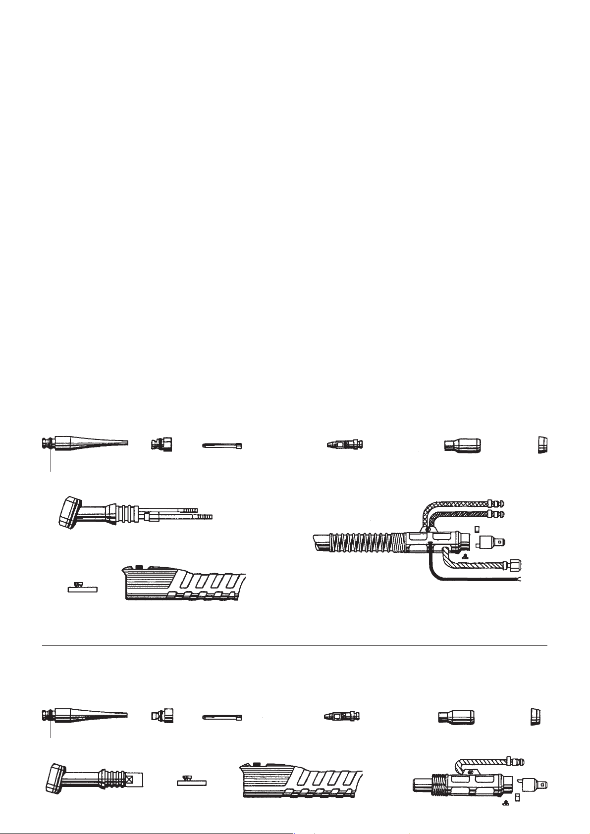
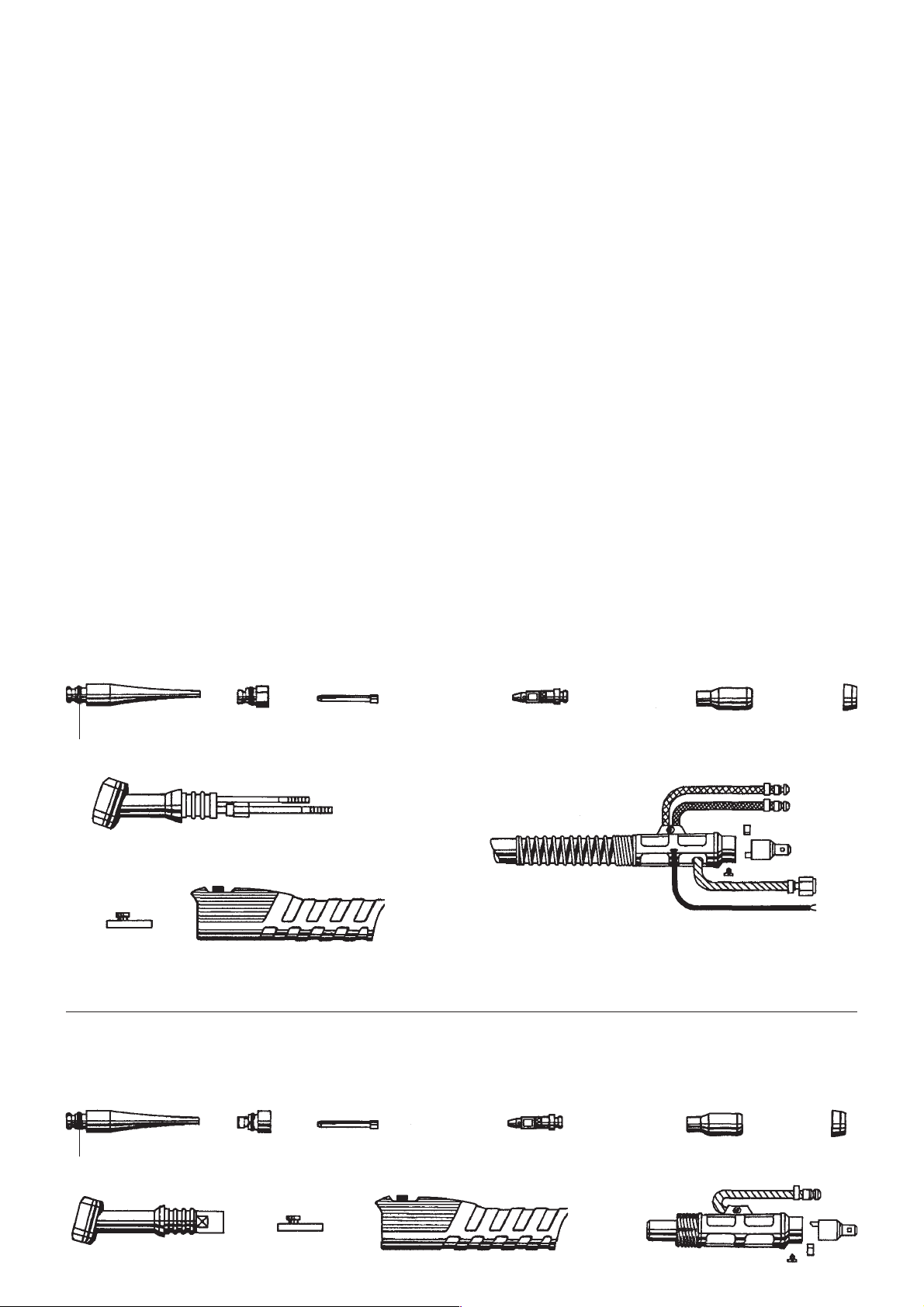
9.0 Schweißbrenner SR 18 und SR 26
Schweißbrenner SR 18
456 7 8 12
11
2
10
9
1
11
Schweißbrenner SR 26
4
2
56 7
9
10
8
1
12
Page 13

10.0 Ersatzteilliste
Pos. Artikel-Bezeichnung Art.-Nr.
1 Brenner kpl. - 4 m Wassergekühlt 090 201 2036 ●
Brenner kpl. - 8 m Wassergekühlt 090 201 2516 ●
Brenner kpl. - 4 m Wassergekühlt mit Fernregler 090 201 2044 ●
Brenner kpl. - 8 m Wassergekühlt mit Fernregler 090 201 2052 ●
Brenner kpl. - 4 m 090 200 9108 ●
Brenner kpl. - 4 m mit Fernregler 090 200 7156 ●
Brenner kpl. - 8 m mit Fernregler 090 200 8055 ●
2 Brennerkörper 132 717 0500 ●
Brennerkörper 132 714 0147 ●
4 Brennerkappe Lang 132 712 7230 ●●
5 Brennerkappe Kurz 132 712 7248 ●●
6 Spannhülse 1,0 mm 132 712 7078 ●●
Spannhülse 1,6 mm 132 712 7086 ●●
Spannhülse 2,4 mm 132 712 7094 ●●
Spannhülse 3,2 mm 132 713 5429 ●●
7 Spannhülsengehäuse 1,0 mm 132 712 7132 ●●
Spannhülsengehäuse 1,6 mm 132 712 7140 ●●
Spannhülsengehäuse 2,4 mm 132 712 7159 ●●
Spannhülsengehäuse 3,2 mm 132 713 5410 ●●
SR 18
SR 26
8 Gasdüse - Keramik Gr. 5 8,0 mm 132 712 7876 ●●
Gasdüse - Keramik Gr. 6 9,5 mm 132 712 7175 ●●
Gasdüse - Keramik Gr. 7 11,0 mm 132 712 7884 ●●
Gasdüse - Keramik Gr. 8 12,5 mm 132 713 5402 ●●
9 Doppeldruckschalter Rot/Grün 132 717 0488 ●●
10 Schaltergehäuse 132 717 0526 ●●
11 O-Ring 132 712 7892 ●●
12 Isolierring 132 712 7256 ●●
11.0 Ersatzteilliste für WIG-Gerät
Bezeichnung Artikel-Nr.
Platine AC-Drive 4 810 619 8170
Platine NT-AC 4252 810 619 8188
Platine HF-AC 4 810 619 8196
Platine FB-Tren 2 810 619 8200
Platine Steck-VR 2 810 619 8226
HF-Drossel 132 719 8234
Bedieneinheit komplett 810 619 8242
4 pol. Kabelbaum 845 019 8251
6 pol. Kabelbaum 845 019 8260
10 pol. Kabelbaum 845 019 8278
Spartransformator 132 714 0244
Schütz B 6-30-10 810 407 3825
Page 14

Contents:
1.0 Specifications
2.0 Scope Of Application
3.0 Commissioning
4.0 Description
5.0 Hints For Operation
6.0 Overloads/Power Fluctuations
7.0 Safety Instructions
8.0 Trouble Shooting
9.0 TIG Torches SR 18 and SR 26
10.0 Spare Parts List Torches
11.0 Spare Parts List TIG 255 AC/DC
12.0 Wiring Diagram
1.0 Specifications
Power Mains : 3~ 400 V +5/-15 V
Mains Frequency : 50-60 Hz
Open Circuit Voltage : 57 V
Welding Current Range : 5-250 A AC/DC, TIG/manual arc
Power Input : TIG 6.6 kVA, electrodes 9.9 kVA AC/DC
Working Voltage : TIG 10.2-20 V AC/DC
Electrodes 20.2-30 V
Max. Current Draw : 16 A
Mains Fuse : 3 x 16 A
Duty Cycle : 75% at 250 A
100% at 220 A
Welding Modes : 2-step/4-step/manual arc
Ignition : selectable, high frequency or touch contact
AC Current : square wave, 50-200 Hz
balance adjustable from -70% to +30%
Pulse Arc : stepless setting
pulse time 0.1 - 2 sec
pulse dwell time 0.1 - 2 sec
pulse base current 0-100 %
Hot Start : steplessly adjustable 0-100%
Up/Down Slope : steplessly adjustable 0.1 - 10 sec
Gas Post Flow : steplessly adjustable 0.1 - 20 sec
Working Range : aluminium from 0.5 mm
steel from 0.3 mm
Power Factor cos ϕ : 0.99
Protection Class : IP 23 S
Type of Cooling : F (fan-cooled)
Insulation Class : F
Temperature Range : operation -10°C to +40°C
storage -20°C to +70°C
Dimensions : 530x330x380 mm
Weight : 33 kg
2.0 Scope Of Application
The TIG welding machine model TIG 255 AC/DC is designed as a compact, easy to operate unit. With it all metals
can be welded. Special consideration has been given to manual arc welding capabilities, i.e. vertical-down
welding.
Other applications are:
- TIG DC welding in 2- or 4-step mode, with or without H.F. ignition
- TIG AC welding in 2- or 4-step mode with H.F. ignition, absolutely square wave current
- pulse welding, AC and DC
- manual arc welding with adjustable hot start
- use of remote hand or foot control unit with all welding processes. With TIG welding arc starting by
remote hand or foot control unit is possible
- approved for operation in areas with increased electrical hazards, i.e. boilers and containers, indicated by the
S mark on the front panel
Page 15
User Responsibility
This machine will perform in conformity with the description contained in the instructions provided. This machine
must be checked periodically. Defective equipment (including power cables and service leads) should not be
used. Parts that are broken, missing, plainly worn, distorted or contaminated, should be replaced immediately.
Should such repair become necessary, it is recommended that such repairs are carried out by qualified persons
approved by Elektra Beckum or its representatives. This machine or any of its parts should not be altered or
changed from standard specifications. The user of this machine shall have the sole responsibility for any
malfunction which results from improper use or unauthorized modification from standard specification, faulty
maintenance, damage or improper repair by anyone other than qualified persons approved by Elektra Beckum
or its representatives.
3.0 Commissioning
Important: This machine and its components have been inspected and tested throughout all production stages.
Before it is packed for shipping each machine undergoes a final computerized inspection, a certificate of same
is included with the machine. After receipt please unpack your machine and check for any visible transport
damage. If such damage is evident please notify your supplier immediately.
When connecting to mains power be sure that the power supplied matches the rated voltage of your machine (see
machine label) and that the outlet is properly earthed/grounded.
This machine must be connected to phases 1,2,3 (L1,L2,L3) and the earth/ground terminal. A neutral wire is not
required. Connect this machine only to a properly earthed/grounded three-phase outlet. If a plug matching your
local standard has to be fitted to the power cable, leave this work to a qualified electrician.
For TIG welding pure Argon (99.996% Helium) is used as shielding gas. Connect machine to gas cylinder only
by means of a suitable and approved pressure reducing and regulating device. The maximum input pressure must
not exceed 10 bar/142 psi.
The earth cable for the work piece clamp should have a minimum cross section of 25mm2.
After setting the ON/OFF switch [1] to ON the machine is operational.
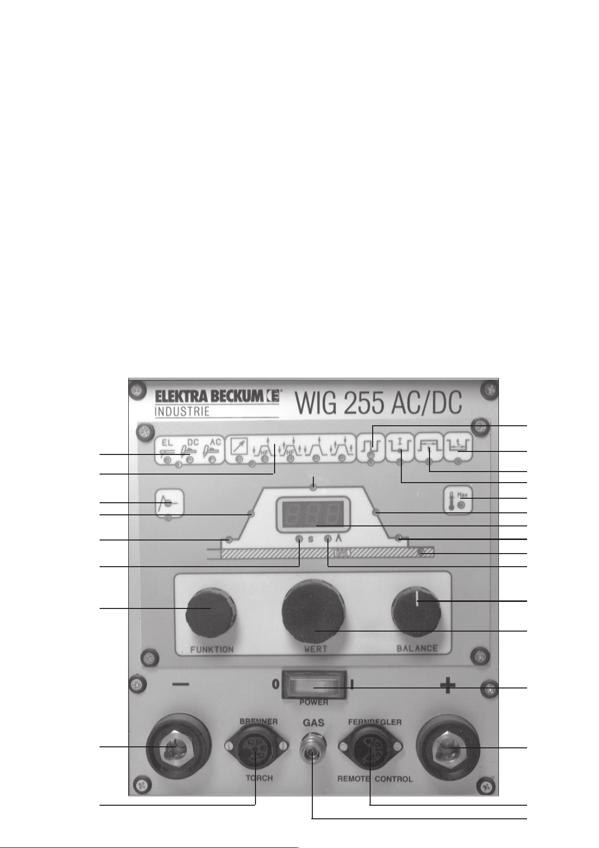
4.0 Description
13
14
12
20
19
25
7
21
15
18
17
16
11
22
10
23
24
26
9
8
1
6
5
2
3
4
Page 16

4.1 Controls
[1] Mains ON/OFF switch
[2] Cable socket: 1. TIG mode: work piece clamp
2. manual arc welding: (+) positive pole
[3] Socket for remote control unit
[4] Coupling for shielding gas line
[5] Socket for TIG torch controls (trigger switch)
[6] Cable socket: 1. TIG mode: torch
2. Manual arc welding: (-) negative pole
[7] Control knob FUNCTION
[8] Control knob VALUE
[9] Control knob ARC
when TIG AC welding sets the balance for regulating the rectifying effect
[10] Digital display
[11] Overload/Power failure indicator
[12] Manual arc welding: hotstart, current addition 0 - 100 %
[13] Welding mode selector: - manual arc welding
- TIG DC welding
- TIG AC welding
[14] Operating mode : - remote control
- 2-step mode with H.F. ignition
- 4-step mode with H.F. ignition
- 2-step mode w/o H.F. ignition
- 4-step mode w/o H.F. ignition
[15] Pulser ON/OFF
[16] Pulser base current setting
[17] Pulser weld time setting 0.1 - 5.0 sec
[18] Pulser dwell time setting 0.1 - 5.0 sec
[19] LED - green: start-up current setting (5-250 A)
[20] LED - green: slope-up time in seconds (0.1 - 10 sec)
[21] LED - green: welding current setting (5 - 250 A)
[22] LED - green: slope-down time in seconds (0.1 - 10 sec)
[23] LED - green: end current setting (5 - 250 A)
[24] LED - green: gas post flow time setting (0 - 20 sec)
[25] LED - red: indicates that a time setting is shown in the display
[26] LED - red: indicates that a current setting is shown in the display
A detailed description of how to set the welding parameters for the different welding modes is given in
sections 4.2 and 4.3 below.
4.1.1Control Knob Function
- with the control knob FUNCTION [7] the function, which parameters need to be changed, is selected. A green
LED indicates the function selected for parameter changing.
- with the control knob VALUE [8] the parameter of the selected mode or function is changed. A red LED
indicates the set mode or parameter. Where applicable, the red LED's under the digital display indicate if a time
(S) or a current (A) setting is changed.
- control knob BALANCE [9] allows to adjust the balance setting of the arc to regulate the rectifying effect when
welding aluminium (TIG AC welding only).
The setting that is active when the machine is switched off is restored when the machine is switched on again.
Page 17
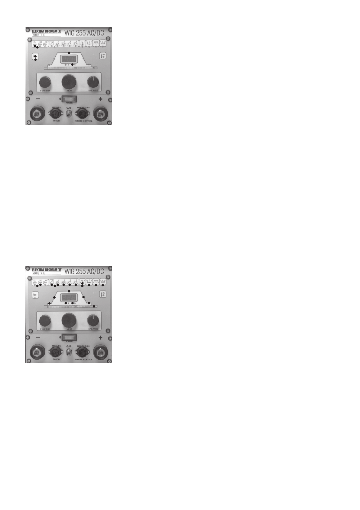
4.2 Manual Arc Welding With Stick Electrodes
- Set switch ON/OFF [1] to ON.
- Turn knob FUNCTION counter-clockwise until the green LED of the welding
mode selector [13] comes on. Turn knob VALUE to activate the manual arc
welding mode (red LED under the EL symbol must be lit).
- Turn knob FUNCTION counter-clockwise until the green LED of the hotstart
function [12] comes on. With knob VALUE set a percentage of the welding
current, which is to be added to the welding current during arc starting. The
percentage is shown in the digital display [19]. The red LED of the hotstart
symbol is lit, indicating that this function is activated.
- Turn knob FUNCTION clockwise to activate the welding current setting or wait
5 seconds, after which the machine will automatically return to the current
setting mode [21]. Set required welding current with knob VALUE. Red LED [26]
indicates a current setting. With these settings of the machine all TIG functions
are deactivated.
All types of stick electrodes can be used, both the negative and the reverse polarity arrangement are possible.
As a special feature this welding machine has a hot-start feature with stepless setting. The set percentage of the
welding current is added to it. The duration of the impulse is 0.2 - 0.4 sec. The advantages are:
- very good arc starting, even with difficult to start electrodes
- sticking of the electrode is nearly eliminated (anti-stick feature)
- With the high current impulse the workpiece material is melted in depth, preventing incomplete fusion defects.
The TIG 255 AC/DC has excellent vertical-down welding capabilities. Its smooth, stable arc keeps the slag from sagging.
4.3 TIG Welding
The TIG 255 AC/DC is suitable for DC welding of carbon steels, stainless steels and copper, as well as for AC welding
of aluminium and aluminium alloys.
4.3.1 TIG DC Welding
- Set switch ON/OFF [1] to ON.
- Turn knob FUNCTION counter-clockwise until the green LED of the welding
mode selector [13] comes on. Turn knob VALUE to activate the TIG DC welding
mode (red LED under the DC symbol must be lit).
- Turn knob FUNCTION clockwise until the green LED of the operating mode
selector [14] comes on. With knob VALUE select the operating mode:
- remote control - remote arc start (see section 4.3.6.)
- 2-step mode with H.F. (see section 4.3.3)
- 4-step mode with H.F. (see section 4.3.4)
- 2-step mode w/o H.F. (see section 4.3.3)
- 4-step mode w/o H.F. (see section 4.3.4)
The red LED indicates the active TIG welding mode.
- Select start-up current setting (green LED [19] on) with knob FUNCTION and set desired start-up current with knob
VALUE from 5-250 A. The selected current is displayed in the digital display, the red LED [26] is lit.
- Select slope-up time setting (green LED [20] on) with knob FUNCTION and set desired duration with knob VALUE.
The digital display shows the time set, the red LED [25] is lit.
- Turn knob FUNCTION to activate the welding current setting (green LED [21] on) and set the welding current with
knob VALUE. The selected welding current shows in the digital display, the red LED [26] is lit.
- With knob FUNCTION activate the slope-down time setting (green LED [22] on), set desired duration with knob value.
The digital display shows the time set, the red LED [25] is lit.
- Turn knob FUNCTION to activate the end current setting (green LED [23] on). Set the required current with knob
VALUE, which is shown in the digital display, the red LED [26] is lit.
- Select gas post flow time setting (green LED [24] on) with knob FUNCTION, and set to any duration between
0 - 20 sec. The duration set is shown in the digital display, the red LED [25] is lit.
Page 18
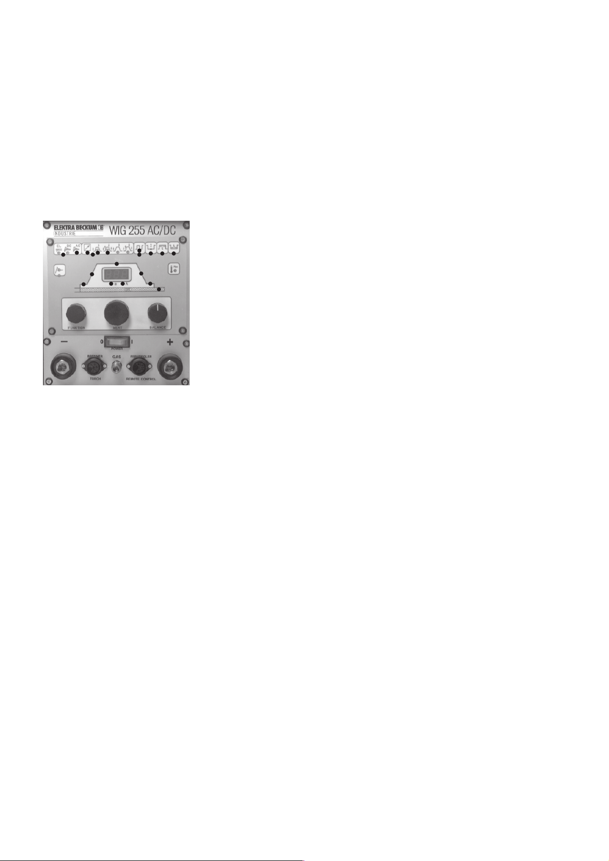
If the pulse function is to be activated for TIG DC welding (description see section 4.3.8), the following additional settings
are required:
- Turn knob FUNCTION to select the pulser setting (green LED [15] on). Turn knob VALUE to activate the pulser (the
red LED, when on, indicates that the pulser is activated).
- With knob FUNCTION select the pulser base current setting (green LED [16] on), then set the pulser base current
with knob VALUE to any amperage between 5 - 250 A. The base current set is shown in the digital display, the red
LED [26] is lit.
- With knob FUNCTION select the pulser weld time setting (green LED [17] on), to set the duration of the weld time
(0.1 - 5 sec.) with knob VALUE. The duration set in seconds is shown in the digital display, the red LED [25] is lit.
- With knob FUNCTION select the pulser dwell time setting (green LED [18] on), to set the duration of the dwell time
(0.1 - 5 sec.) with knob VALUE. The duration set in seconds is shown in the digital display, the red LED [25] is lit.
4.3.2 TIG AC Welding
- Set switch ON/OFF [1] to ON.
- Turn knob FUNCTION counter-clockwise until the green LED of the welding
mode selector [13] comes on. Turn knob VALUE to activate the TIG AC welding
mode (red LED under the AC symbol must be lit).
- Turn knob FUNCTION clockwise until the green LED of the operating mode
selector [14] comes on. With knob VALUE select the operating mode:
- remote control - remote arc start (see section 4.3.6.)
- 2-step mode with H.F. (see section 4.3.3)
- 4-step mode with H.F. (see section 4.3.4)
The red LED indicates the active TIG welding mode.
- Select start-up current setting (green LED [19] on) with knob FUNCTION and set
desired start-up current with knob VALUE from 5-250 A. The selected current
is displayed in the digital display, the red LED [26] is lit.
- Select slope-up time setting (green LED [20] on) with knob FUNCTION and set desired duration with knob VALUE.
The digital display shows the time set, the red LED [25] is lit.
- Turn knob FUNCTION to activate the welding current setting (green LED [21] on) and set the welding current with
knob VALUE. The selected welding current shows in the digital display, the red LED [26] is lit.
- With knob FUNCTION activate the slope-down time setting (green LED [22] on), set desired duration with knob value.
The digital display shows the time set, the red LED [25] is lit.
- Turn knob FUNCTION to activate the end current setting (green LED [23] on). Set the required current with knob
VALUE, which is shown in the digital display, the red LED [26] is lit.
- Select gas post flow time setting (green LED [24] on) with knob FUNCTION, and set to any duration between
0 - 20 sec. The duration set is shown in the digital display, the red LED [25] is lit.
If the pulse function is to be activated for TIG AC welding (description see section 4.3.8), the following additional settings
are required:
- Turn knob FUNCTION to select the pulser setting (green LED [15] on). Turn knob VALUE to activate the pulser (the
red LED, when on, indicates that the pulser is activated).
- With knob FUNCTION select the pulser base current setting (green LED [16] on), then set the pulser base current
with knob VALUE to any amperage between 5 - 250 A. The base current set is shown in the digital display, the red
LED [26] is lit.
- With knob FUNCTION select the pulser weld time setting (green LED [17] on), to set the duration of the weld time
(0.1 - 5 sec.) with knob VALUE. The duration set in seconds is shown in the digital display, the red LED [25] is lit.
- With knob FUNCTION select the pulser dwell time setting (green LED [18] on), to set the duration of the dwell time
(0.1 - 5 sec.) with knob VALUE. The duration set in seconds is shown in the digital display, the red LED [25] is lit.
- Balance setting with knob BALANCE, see details in section 4.3.7.
In TIG AC welding mode the unit uses the automatic frequency adjustment feature, setting the AC frequency between
50 - 200 Hz. With a low current setting (approx. 50 A), 200 Hz are used for a good cleaning effect when welding thin
sheet metal from 0.5 mm aluminium, with only minimal energy input.
When welding with high currents (approx. 250 A) the unit operates at 50 Hz. A sufficient oxide cleaning effect is
guaranteed by the high energy input.
Within the current range the arc frequency is always automatically set to provide optimal performance.
Page 19
4.3.3 TIG Torch Connection
20
21
Brenner - Torch
The welding current lead connects to socket [6], the torch control leads to socket [5]. The gas hose connects to the quick
coupling [4], the work piece clamp connects to socket [2]. In addition a foot-operated remote control unit can be
connected to socket [3]. The set welding current can also be regulated by means of a potentiometer build into the torch.
Bild 1
Note: If both a remote control unit and torch with potentiometer are connected to the machine, they will interfere with
each other. Always connect only one remote control potentiometer.
4.3.4 Starting The Arc
4.3.4.1 Arc Starting by Touching The Work Piece with the Electrode (Scratch Start)
G
Approaching Short circuit Ignition of
the work piece and heating up the arc
4.3.4.2 Touch-free High-Frequency Arc Starting
= 2 mm
Approaching Starting the Ignition of
the work piece pilot arc by the arc
G
I
high-frequency pulses
G G
G G
I I
4.3.5 2-Step Mode
Pressing the red trigger switch (20) starts the welding operation. After the arc has ignited (by either H.F. or touch-contact
ignition), the welding current, within the set slope-up period, slopes up from the selected start-up current to the set
welding current.
Releasing the trigger switch (20) stops the arc immediately.
2-Takt
2-step
mode
Brennerschalter
Trigger Switch
20
I
Zündung
Ignition
Stromanstieg
Up-slope
t
10
Page 20
4.3.6 4-Step Mode
Pressing the red trigger switch (20) starts the welding operation (ignition by either H.F. or touch-contact ignition). While
the trigger switch is held down, the arc operates at the start-up current. The start-up current is set as in 2-step mode,
but should be set to a minimum of 5 A (pilot arc). After the trigger switch is released the welding current slopes up to
the selected welding current, within the period (0.1 - 10 sec) set.
Pressing the red trigger switch (20) again engages the slope-down function, the welding current, within the preset slopedown time, slopes down to the selected base current for end crater filling. Releasing the trigger switch ends the welding
operation.
Activating the green trigger switch (21) at any given time during the welding operation reduces the welding current to
the selected base current, without interrupting the actual welding operation. When the green trigger switch is released
the current slopes up again.
I
4-Takt
4-step
mode
Brennerschalter
Stromanstieg
Up-slope
Zündung
Ignition
Stromabsenkzeit
Down-slope
11
t
Trigger Switch
20
Stromanstieg
I
Up-slope
Zündung
Ignition
Brennerschalter
10
10
t
Trigger Switch
20
21
4.3.7 Balance Control
Welding aluminium with alternating current generates a rectifying effect, causing the amplitudes of the square wave to
be of different intensity. With the balance control this rectifying effect can be adjusted from +30% to -70%.
The negative amplitude is longer, causing an unstable arc, the cleaning action is poor, deep penetration.
+
Lichtbogen
strom
0
Arc current
t
–
The positive amplitude is longer, high heat input, little penetration, wide weld seams.
Note: The high heat input may damage the electrode.
+
Lichtbogen
strom
0
Arc current
t
–
Page 21
4.3.8 Pulsed Current Welding
Pulse arc welding is an arc welding variation in which the power is cyclically programmed to pulse so that effective but
short duration values of power can be utilized. Such short duration values are significantly different from the average
value of power. The arc operates at an infinitely adjustable base current (function [16], between 5 - 250 A).
Pulse duration [17] and pulse dwell time [18] are each steplessly adjustable between 0.1 - 5 sec.
Pulsdauer - Pulse time
17
t
21
Ip
19
Brennerschalter
Trigger Switch
Ig
Stromanstieg
Up-slope
20 18
Pulspause - Pulse dwell time
Advantages:
- welding of very thin material
- only little heat input per unit length when welding high-alloy steel
- joining of thick with thin material
4.3.9 Remote Control
A remote control unit, either hand or foot operated, has to be connected to socket [3] and the machine set for remote
control operation [14]. This operating mode disables the TIG torch trigger switches. The arc is started by the remote
control unit and the welding current adjusted between the preset start-up current and maximum welding current.
The operator can do precision welds without having to move his hand on the torch to start the welding process.
In 2-step and 4-step mode (both with and without H.F. ignition) a remote control unit can also be used to regulate the
welding current, however the arc has to be started by activating the red torch trigger switch.
5.0 Practical Hints For Operation
To ensure good arc starting and good welding results the following should be adhered to:
5.1 Types of Electrodes
For DC TIG welding only thoriated electrodes are recommended for use, e.g.
WT 20 1.8-2.2 % thorium oxide, color code: red
WT 30 2.8-3.2 % thorium oxide, color code: purple
For AC TIG welding only pure tungsten electrodes are recommended, e.g.
W - tungsten electrode, color code: green
5.2 Electrode Diameter
The electrode diameter should match the welding current. General values are:
less than 80 A: diameter 1.0 mm
70 A to 140 A: diameter 1.6 mm
130 A to 250 A: diameter 2.5 mm
with AC >220 A: diameter 3.2 mm
5.2.2 Current-Carrying Capacities of Tungsten Electrodes
Diameter Welding Current with Gas Shroud
Direct Current Alternating Current with Filter
(negative Capacitor **
electrode) (negative electrode polarity)
with 2% Pure Tungsten with 2% Size Diameter
Thorium*
mm A A A mm
)
Thorium
1.0 ... 80 ... 30 30 ... 60 4 ... 5 6.5 ... 8
1.6 10 ... 140 30 ... 70 40 ... 100 4 ... 6 6.5 ... 9.5
2.4 20 ... 230 50 ... 110 70 ... 150 6 ... 8 9.5 ... 12.7
3.2 30 ... 310 100 ... 170 130 ... 200 7 ... 8 11.2 ... 12.7
* for pure tungsten electrodes the upper values are approx. 40% lower
** without balance the values shown are approx. 50% higher
Page 22
5.3 Electrode Tip Ground
p
Electrodes for DC welding have to be ground in longitudinal direction only. Do not grind electrodes <=1.6 mm diameter
for AC welding at all, over 1.6 mm diameter with an acute-angled tip with a dull point. When welding with alternating
current the electrode will automatically form a tear shape drop at the tip.
DC welding
(straight polarity)
~30°
The electrode is normally ground in longitudinal direction. For special applications grinding marks have to be removed
by polishing.
Länge ~ 2 x D
D
D
AC welding
D < 1.6 mm
D
~ 90°
>
D 1.6 mm
=
D
With larger diameter the electrode tip is
ground. When welding an tear shape
drop forms automatically at the tip.
5.4 Shielding Gas
Too much gas flow can reduce the arc starting ability. The correct gas flow rate is depending on the base metal and the
work piece thickness.
Argon consumption in l/min
10
9
Nickel
1
Aluminium, Magnesium, Kupfer
Stahl, Chrom-Nickel-Stahl
23
Work
4
iece thickness mm Gas shroud diameter mm
5
67
8
7
6
5
4
85
10 15 20
5.5 Standard Values for TIG Welding
Plain and alloyed steel
DC; negative electrode polarity; welding position f; butt weld
Material Weld Type No. of Layers Diameter of Welding
Thickness Electrode Welding Rod Current
mm mm mm A
1.0 II 1 1 or 1.6 1.6 or 2.0 30 ... 40
2.0 II 1 1.6 or 2.4 1.6 or 2.0 70 ... 80
3.0 II 1 or 2 2.4 2.4 70 ... 90
4.0 II or V 2 2.4 2.4 70 ... 130
5.0 V 3 2.4 or 3.2 2.4 or .,0 75 ... 130
6.0 V 3 2.4 or 3.2 2.4 or 3.0 75 ... 130
Page 23

Aluminium
AC; negative electrode polarity; welding position f; butt weld
Material Weld Type No. of Layers Diameter of Welding
Thickness Electrode Welding Rod Current
mm mm mm A
1.0 II 1 1.6 or 2.4 2.0 40 ... 50
2.0 II 1 1.6 or 2.4 3.0 60 ... 80
3.0 II 1 2.4 3.0 110 ... 130
4.0 II 1 or 2 2.4 or 3.2 3.0 120 ... 150
5.0 V 1 or 2 3.2 3.0 150 ... 200
Copper
DC; negative electrode polarity; welding position f; butt weld
Material Weld Type No. of Layers Durchmesser Welding
Thicknes Electrode Welding Rod Current
mm mm mm A
1.5 II 1 1.6 2.0 90 ... 100
3.0 II 1 3.2 3.0 150 ... 200
5.0 V 2 4.0 4.0 180 ... 300
Note: for vertical down and overhead welding positions reduce welding current by 10 - 20 %.
6.0 Overloads/Power Fluctuations
6.1 Overloads
The TIG 255 AC/DC is protected against overloads by several independent protection devices. If the permissible
duty cycle is exceeded the machine switches itself off automatically. This is indicated by a flashing control LED
[11]. After a short cooling-down period the machine is operational again.
Note: Do not switch the power off during the cooling-down period, this would also cut the power for the cooling
fan, thus prolonging the cooling-down period.
6.2 Power Fluctuations
If the mains voltage drops more than 10% below its rated value, the machine switches off automatically because
the primary currents are becoming too high.
This is indicated by the control LED [11], burning steady. Switch machine off and on again to reset this error
message.
7.0 Safety Instructions
- This TIG welding machine should only be used for its intended application (TIG welding and manual arc
welding with stick electrodes)
- Know and adhere to all applicable safety codes and standards.
- Always wear appropriate apparel when welding.
- Never work without welding visor and gloves, as with TIG welding the arc emits very intense ultraviolet
radiation.
- Operate machine only in dry surroundings.
- Operate machine only on power supply circuits having a fully operational protective bonding circuit (earth/
ground lead).
- Do not operate near running electronic data processing equipment. The machine’s H.F. ignition may interfere
with the electronics.
Page 24
8.0 Trouble Shooting
8.1 Arc does not start when in TIG Welding Mode
Cause: Torch defect
Earth cable broken or not conducting
Tungsten electrode dirty
8.2 Machine works only on minimal welding current
Cause: Potentiometer in torch or remote control unit faulty
8.3 Poor Arc Starting
Cause: - no or insufficient gas supply
- tungsten electrode tip ground wrong
- wrong electrode diameter
- tungsten electrode covered with oxides or other impurities
- work piece surface not free of grease or oil
8.4 Control LED [11] stays on continuously
Cause: voltage drop of more than 10% below the rated voltage. Reason may be an extension cord with too
small a lead cross section.
9.0 TIG Torch SR 18 and SR 26
456 7 8 12
11
2
10
9
TIG Torch SR 18
1
11
TIG Torch SR 26
4
2
56 7
9
10
8
1
12
Page 25

10.0 Spare Parts List Torches
Pos. Description Stock-No.
1 Torch ass'y - 4 mtr, water-cooled 0902012036 ●
Torch ass'y - 8 mtr, water-cooled 0902012516 ●
Torch ass'y - 4 mtr, water-cooled, remote control 0902012044 ●
Torch ass'y - 8 mtr, water-cooled, remote control 0902012052 ●
Torch ass'y - 4 mtr 0902009108 ●
Torch ass'y - 4 mtr, with remote control 0902007156 ●
Torch ass'y - 8 mtr, with remote control 0902008055 ●
2 Torch body 1327170500 ●
Torch body 1327140147 ●
4 Back cap, long 1327127230 ●●
5 Back cap, short 1327127248 ●●
6 Collet 1.0 mm 1327127078 ●●
Collet 1.6 mm 1327127086 ●●
Collet 2.4 mm 1327127094 ●●
Collet 3.2 mm 1327135429 ●●
7 Collet body 1.0 mm 1327127132 ●●
Collet body 1.6 mm 1327127140 ●●
Collet body 2.4 mm 1327127159 ●●
Collet body 3.2 mm 1327135410 ●●
SR 18
SR 26
8 Gas shroud, ceramic, size 5 8.0 mm 1327127876 ●●
Gas shroud, ceramic, size 6 9.5 mm 1327127175 ●●
Gas shroud, ceramic, size 7 11.0 mm 1327127884 ●●
Gas shroud, ceramic, size 8 12.5 mm 1327135402 ●●
9 Twin touch contact switch red/green buttons 1327170488 ●●
10 Switch housing 1327170526 ●●
11 O-ring for back cap 1327127892 ●●
12 Insulating ring 1327127256 ●●
11.0 Spare Parts List TIG 255 AC/DC
Description Stock-No.
PCB AC-Drive 4 8106198170
PCB NT-AC 4252 8106198188
PCB HF-AC 4 8106198196
PCB FB-Tren 2 8106198200
PCB Steck-VR 2 8106198226
H.F. choke 1327198234
Front panel PCB ass'y 8106198242
Wire harness, 4 leads 8450198251
Wire harness, 6 leads 8450198260
Wire harness, 10 leads 8450198278
Transformer 1327140244
Contactor B 6-30-10 8104073825
Page 26

Sommaire :
1.0 Caractéristiques techniques 5.0 Consignes d'utilisation
2.0 Domaines d'application 6.0 Surcharge/Erreur secteur
3.0 Mise en service 7.0 Indication des dangers
4.0 Description fonctionnelle 8.0 En cas de panne
9.0 Schéma électrique
1.0 Caractéristiques techniques
Tension d'alimentation : 3~400 V
Fréquence du réseau : 50-60 Hz
Tension à vide : 57 V
Capacité : 5-250 A AC/DC, électrode
Puissance d'entrée : 6,6 KVA TIG AC/DC, 9,9 KVA électrode
Tension de service : 10,2-20 V TIG AC/DC
20,2-30 V électrode
Intensité max. d'entrée : 16 A
Fusible de secteur : 16 A
Facteur de marche : 250 A - 75 %
220 A - 100 %
Modes : 2 temps/ 4 temps/ électrode
Amorçage de l'arc : commutable, haute fréquence ou au contact
Courant alternatif : rectangulaire, 50-200 Hz
balance réglable de -70% à 30%
Mode pulsé : réglable en continu
durée d'impulsion 0,1-2 s
intervalle entre deux impulsions 0,1-2 s
courant de base 0-100 %
Hotstart : réglable en continu 0-100 %
Up/Down-Slope : réglable en continu 0,1-10 s
(montée/descente du courant)
Durée post-gaz : réglable en continu 0,1-20 s
Plages de travail : à partir de 0,5 mm pour l'aluminium
à partir de 0,3 mm pour l'acier
Facteur puiss. cos j : 0,99
Indice de protection : IP 23 S
Type de refroidissement : F
Classe d'isolation : F
Plage de température : -10 - +40°C en exploitation
-20 - +70°C lors du stockage
Dimensions : 530x330x380
Poids : environ 33 kg
2.0 Domaines d'application
L'appareil TIG 255 AC/DC est un appareil adapté aux exigences de la pratique et conforme aux normes de
sécurité sur les chantiers. Il peut être utilisé pour souder tous les métaux. Une attention particulière a été
accordée au comportement de l'arc lors du soudage à l'électrode (sécurité en soudure verticale
descendante).
Les autres domaines d'application sont :
- soudage TIG avec courant continu, à 2 ou 4 temps, avec ou sans amorçage HF
- soudage TIG avec courant alternatif , à 2 ou 4 temps, avec amorçage HF
courant alternatif rectangulaire absolu (Square Wave).
- soudage pulsé avec courant continu et alternatif
- soudage à électrode en baguette avec hotstart réglable
- utilisation de tous les procédés de soudage avec commande à distance manuelle ou au pied. Possibilité
d'amorçage par commande à distance pour le soudage TIG.
- utilisable dans tous les environnements à risque électrique accru (par exemple chaudières et réservoirs).
L'installation porte donc le sigle "S" (anciennement sigle "K").
- usage fixe, sur chantier et en liaison avec des groupes électrogènes.
Page 27
Responsabilité du fait du produit/Garantie :
Les manipulations et les utilisations non mentionnées dans la notice requièrent l'autorisation écrite de
l'entreprise Elektra Beckum AG, Postfach 1352, 49703 Meppen, Allemagne.
Toutes les machines et leurs accessoires sont fournis avec un bon de garantie. Afin de pouvoir faire
intervenir la garantie en cas de problème et de veiller à la sécurité du produit, nous vous invitons à remplir le
bon de garantie dès votre achat et à retourner le coupon-réponse au fabricant.
Veuillez vous adresser directement à votre revendeur pour les réparations sous garantie.
Les travaux sous garantie sont toujours effectués par des centres techniques agréés.
Même en dehors de la période de garantie, seuls les centres techniques agréés sont autorisés à réparer
l'appareil.
Veuillez conserver les factures des réparations !
3.0 Mise en service
Attention : les appareils sont construits et contrôlés en usine avec le plus grand soin. Tous les appareils de
soudage sont soumis à des essais informatisés et reçoivent en usine un certificat. Inspectez la machine juste
après l'avoir déballée pour vous assurer qu'elle n'a pas été abîmée durant le transport. En cas de problème,
informez immédiatement la société qui a effectué la livraison. Lors du branchement de l'appareil, vérifiez
bien la tension de raccordement (voir plaque signalétique). Le branchement nécessite les lignes L1, L2, L3
et PE. Reliez l'appareil à une prise de courant CEE à 5 pôles correctement installée. L'appareil utilise
exclusivement de l'argon (hélium) comme gaz inerte de soudage TIG. Prévoir impérativement un dispositif
détendeur adéquat pour le raccordement au gaz (10 bars max.) La pince de masse doit être reliée à un
conducteur d'au moins 25 mm2 de section. Une fois que le commutateur principal [1] a été actionné,
l'appareil est prêt à l'emploi.
4.0 Description fonctionnelle
13
14
12
20
19
25
7
21
15
18
17
16
11
22
10
23
24
26
9
8
1
6
5
2
3
4
Page 28

4.1 Eléments de commande
1 Interrupteur d'alimentation ON/OFF
2 Raccordement : 1. pince de masse en soudage TIG
2. pôle (+) en soudage manuel à l'électrode
3 Raccordement de la commande à distance manuelle ou au pied
4 Raccordement du gaz inerte
5 Raccordement de la commande de la torche
6 Raccordement : 1. torche en soudage TIG
2. pôle (-) en soudage manuel à l'électrode
7 Potentiomètre rotatif de sélection des fonctions
8 Potentiomètre rotatif de réglage des valeurs
9 Potentiomètre rotatif de réglage de l'arc
Balance de réglage de l'effet redresseur en soudage TIG AC
10 Afficheur digital
11 Affichage de surcharge-erreur secteur
12 En cas de soudage manuel à l'électrode : hotstart, addition de courant de 0 à 100 %
13 Affichage des types de soudage : - soudage à l'électrode
- soudage TIG DC
- soudage TIG AC
14 Affichage des modes de fonctionnement : - commande à distance
- soudage à 2 temps haute fréquence
- soudage à 4 temps haute fréquence
- soudage à 2 temps sans haute fréquence
- soudage à 4 temps sans haute fréquence
15 Mode pulsé ON/OFF
16 Réglage du courant de base d'impulsion
17 Réglage de la durée d'impulsion de 0,1 à 5 s
18 Réglage de l'intervalle entre les impulsions de 0,1 à 5 s
19 DEL verte : Fonction de réglage du courant de démarrage 5 - 250 A
20 DEL verte : Fonction de réglage de la durée de montée 0,1 - 10 s
21 DEL verte : Fonction de réglage du courant de soudage 5 - 250 A
22 DEL verte : Fonction de réglage de la durée de descente 0,1 - 10 s
23 DEL verte : Fonction de réglage du courant de coupure 5 - 250 A
24 DEL verte : Fonction de réglage de la durée post-gaz 0 - 20 s
25 DEL rouge pour l'affichage du temps sur la zone d'affichage digital
26 DEL rouge pour l'affichage des ampères sur la zone d'affichage digital
Le fonctionnement des différents éléments de commande est décrit aux points 4.2 et 4.3.
4.1.1Légende
- 1 Potentiomètre "Fonction" (7) : active en cours d'utilisation toutes les fonctions réglables ;
activation signalée par la diode DEL verte.
- 2 Potentiomètre "Valeur" (8) : permet de régler la valeur pour une fonction sélectionnée ; activation
signalée par une diode DEL rouge.
- 3 Potentiomètre "Balance" (9) : réglage séparé de l'effet redresseur en mode TIG AC (soudage de
l'aluminium).
Page 29
4.2 Description fonctionnelle du soudage manuel à l'électrode
- Mettre l'appareil sous tension en actionnant l'interrupteur (1).
- Potentiomètre rotatif "Fonction" vers la gauche jusqu'à ce que la DEL verte du
groupe "Affichage modes de soudage" (13) s'allume. Potentiomètre rotatif
"Valeur" sur fonction électrode, DEL rouge s'allume et indique que la fonction est
activée.
- Potentiomètre rotatif "Fonction" vers la gauche jusqu'à ce que la DEL verte du
groupe "Hotstart" (12) s'allume. Potentiomètre rotatif "Valeur" : réglage du
hotstart de 0 à 100 % (addition de courant proportionnelle au courant de soudage
choisi), indication du pourcentage dans la zone d'affichage digital (19). La DEL
rouge de la fonction "Hotstart" s'allume et indique que la fonction est activée.
- Potentiomètre rotatif "Fonction" vers la droite sur fonction "Courant de soudage"
(21) ou attendre environ 5 s que la fonction passe automatiquement sur "Courant
de soudage" (21). Potentiomètre rotatif "Valeur", réglage du courant de soudage,
DEL rouge (26) indique le réglage en ampères. Les réglages du soudage TIG sont
désactivés dans cette fonction.
Le porte-électrode et la pince de masse sont raccordés aux prises 2 et 6. Il est possible de souder avec tous les types
d'électrode (électrodes à souder aux pôles plus et moins).
Cet appareil dispose en outre d'un hotstart réglable en continu. Le réglage se fait en pourcentage de l'impulsion de
courant. La durée de l'impulsion est comprise entre 0,2 et 0,4 s.
Avantages du hostart : - très bon comportement à l'amorçage avec des électrodes difficiles à amorcer.
- empêche dans une large mesure que les électrodes adhèrent à la matière ("anti stick").
- l'impulsion de courant fait fondre en profondeur le métal de base, ce qui prévient le
manque de liaison.
L'appareil TIG 255 AC/DC se distingue par ses propriétés remarquables en soudure verticale descendante grâce à l'arc
régulier à combustion stable qui empêche le laitier de glisser vers le bas.
A la mise sous tension de l'appareil, les derniers paramètres activés s'affichent.
4.3 Description fonctionnelle du soudage TIG
L'appareil TIG 255 AC/DC permet de souder avec du courant continu l'acier, l'acier spécial et les métaux
composés autres que l'aluminium.
Le soudage sous courant alternatif permet de travailler l'aluminium et les alliages d'aluminium.
4.3.1Soudage TIG DC
- Mettre l'appareil sous tension en actionnant l'interrupteur (1).
- Potentiomètre rotatif "Fonction" vers la gauche jusqu'à ce que la DEL verte
du groupe "Affichage modes de soudage" (13) s'allume. Potentiomètre rotatif
"Valeur" sur TIG DC, la DEL rouge s'allume et indique que la fonction est
activée.
- Potentiomètre rotatif "Fonction" vers la droite jusqu'à ce que la DEL verte de
la fonction "Affichage modes" (14) s'allume. Potentiomètre rotatif "Valeur"
Réglage du mode :
- Démarrage à distance (description au point 4.3.6)
- Commande à 2 temps HF (description au point 4.3.3)
- Commande à 4 temps HF (description au point 4.3.4)
- Commande à 2 temps sans HF (description au point 4.3.3)
- Commande à 4 temps sans HF (description au point 4.3.4), la DEL rouge
s'allume et indique l'élément activé.
- Potentiomètre rotatif "Fonction" sur "Courant de démarrage" (19), la DEL verte s'allume. Potentiomètre rotatif
"Valeur" : réglage du courant de démarrage de 5 à 250 A. La zone d'affichage digital (10) indique la valeur
choisie en ampères, la DEL rouge (26) est activée.
- Potentiomètre rotatif "Fonction" sur "Durée de montée" (20), la DEL verte s'allume. Potentiomètre rotatif
"Valeur" : réglage de la durée de montée de 0,1 à 10 s. La zone d'affichage digital (10) indique la valeur
sélectionnée en secondes, la DEL rouge (25) est activée.
- Potentiomètre rotatif "Fonction" sur "Courant de soudage" (21), la DEL verte s'allume. Potentiomètre rotatif
"Valeur" : réglage du courant de soudage de 5 à 250 A. La zone d'affichage digital (10) indique la valeur choisie
en ampères, la DEL rouge (26) est activée.
- Potentiomètre rotatif "Fonction" sur "Durée de descente" (22), la DEL verte s'allume. Potentiomètre rotatif
"Valeur" : réglage de la durée de descente de 0,1 à 10 s. La zone d'affichage digital (10) indique la valeur
choisie en secondes, la DEL rouge (25) est activée.
- Potentiomètre rotatif "Fonction" sur "Courant de coupure" (23), la DEL verte s'allume. Potentiomètre rotatif
"Valeur" : réglage du courant de coupure de 5 à 250 A. La zone d'affichage digital (10) indique la valeur choisie
en ampères, la DEL rouge (26) est activée.
- Potentiomètre rotatif "Fonction" sur "Durée post-gaz" (24), la DEL verte s'allume. Potentiomètre rotatif "Valeur" :
réglage de la durée post-gaz de 0 à 20 s. La zone d'affichage digital (10) indique la valeur choisie en secondes,
la DEL rouge (25) est activée.
Page 30
Lorsqu'il est nécessaire d'activer également la fonction pulsée pour le soudage TIG DC, respecter l'ordre suivant
(description du soudage pulsé au point 4.3.8) :
- Potentiomètre rotatif "Fonction" vers la droite jusqu'à ce que la DEL verte du groupe "Mode pulsé" (15) s'allume.
Tourner le potentiomètre rotatif "Valeur", la DEL rouge s'allume, le mode pulsé est activé.
- Potentiomètre rotatif "Fonction" vers la droite jusqu'à ce que la DEL verte du groupe "Réglage courant d'impulsion"
(16) s'allume. Potentiomètre rotatif "Valeur" : réglage du courant d'impulsion de 5 à 250 A. La zone d'affichage digital
(10) indique la valeur choisie en ampères, la DEL rouge (26) est activée.
- Potentiomètre rotatif "Fonction" vers la droite jusqu'à ce que la DEL verte du groupe "Réglage durée d'impulsion"
(17) s'allume. Potentiomètre rotatif "Valeur" : réglage de la durée d'impulsion de 0,1 à 5 s. La zone d'affichage digital
(10) indique la valeur choisie en secondes, la DEL rouge (25) est activée.
- Potentiomètre rotatif "Fonction" vers la droite jusqu'à ce que la DEL verte du groupe "Réglage intervalle entre
impulsions" (18) s'allume. Potentiomètre rotatif "Valeur" : réglage de la durée d'intervalle entre impulsions de 0,1
à 5 s. La zone d'affichage digital (10) indique la valeur choisie en secondes, la DEL rouge (25) est activée.
4.3.2Soudage TIG AC
- Mettre en marche l'appareil en actionnant l'interrupteur (1).
- Potentiomètre rotatif "Fonction" vers la gauche jusqu'à ce que la DEL verte du
groupe "Affichage modes de soudage" (13) s'allume. Potentiomètre rotatif
"Valeur" sur TIG AC, la DEL rouge s'allume et signale que la fonction est
activée.
- Potentiomètre rotatif "Fonction" vers la droite jusqu'à ce que la DEL verte du
groupe "Affichage modes" (14) s'allume. Réglage du mode sur le potentiomètre
rotatif "Valeur" :
- Démarrage à distance (description au point 4.3.6)
- Commande à 2 temps HF (description au point 4.3.3)
- Commande à 4 temps HF (description au point 4.3.4), la DEL rouge s'allume
et indique la pièce activée.
- Potentiomètre rotatif "Fonction" sur "Courant de démarrage" (19), la DEL verte
s'allume. Potentiomètre rotatif "Valeur" : réglage du courant de démarrage de
5 à 250 A. La zone d'affichage digital (10) indique la valeur choisie en ampères,
la DEL rouge (26) est activée.
- Potentiomètre rotatif "Fonction" sur "Durée de montée" (20), la DEL verte s'allume. Potentiomètre rotatif "Valeur":
réglage de la durée de montée de 0,1 à 10 s. La zone d'affichage digital (10) indique la valeur sélectionnée en
secondes, la DEL rouge (25) est activée.
- Potentiomètre rotatif "Fonction" sur "Courant de soudage" (21), la DEL verte s'allume. Potentiomètre rotatif
"Valeur" : réglage du courant de soudage de 5 à 250 A. La zone d'affichage digital (10) indique la valeur choisie en
ampères, la DEL rouge (26) est activée.
- Potentiomètre rotatif "Fonction" sur "Durée de descente" (22), la DEL verte s'allume. Potentiomètre rotatif "Valeur":
réglage de la durée de descente de 0,1 à 10 s. La zone d'affichage digital (10) indique la valeur choisie en secondes,
la DEL rouge (25) est activée.
- Potentiomètre rotatif "Fonction" sur "Courant de coupure" (23), la DEL verte s'allume. Potentiomètre rotatif "Valeur" :
réglage du courant de coupure de 5 à 250 A. La zone d'affichage digital (10) indique la valeur choisie en ampères,
la DEL rouge (26) est activée.
- Potentiomètre rotatif "Fonction" sur "Durée post-gaz" (24), la DEL verte s'allume. Potentiomètre rotatif "Valeur" :
réglage de la durée post-gaz de 0 à 20 s. La zone d'affichage digital (10) indique la valeur choisie en secondes, la
DEL rouge (25) est activée.
Lorsqu'il est nécessaire d'activer également la fonction d'impulsion pour le soudage TIG AC, respecter l'ordre suivant
(description du soudage pulsé au point 4.3.8) :
- Potentiomètre rotatif "Fonction" vers la droite jusqu'à ce que la DEL verte du groupe "Mode pulsé" (15) s'allume.
Tourner le potentiomètre rotatif "Valeur", la DEL rouge s'allume, le mode pulsé est activé.
- Potentiomètre rotatif "Fonction" vers la droite jusqu'à ce que la DEL verte du groupe "Réglage courant d'impulsion"
(16) s'allume. Potentiomètre rotatif "Valeur" : réglage du courant d'impulsion de 5 à 250 A. La zone d'affichage digital
(10) indique la valeur choisie en ampères, la DEL rouge (26) est activée.
- Potentiomètre rotatif "Fonction" vers la droite jusqu'à ce que la DEL verte du groupe "Réglage durée d'impulsion"
(17) s'allume. Potentiomètre rotatif "Valeur" : réglage de la durée d'impulsion de 0,1 à 5 s. La zone d'affichage digital
(10) indique la valeur choisie en secondes, la DEL rouge (25) est activée.
- Potentiomètre rotatif "Fonction" vers la droite jusqu'à ce que la DEL verte du groupe "Réglage intervalle entre
impulsions" (18) s'allume. Potentiomètre rotatif "Valeur" : réglage de la durée d'intervalle entre impulsions de 0,1
à 5 s. La zone d'affichage digital (10) indique la valeur choisie en secondes, la DEL rouge (25) est activée.
- Potentiomètre rotatif "Balance", description au point 4.3.7.
L'installation possède un dispositif d'adaptation automatique de la fréquence de 50 à 200 Hz en mode TIG AC. Elle
utilise ainsi une fréquence de 200 Hz pour souder à des intensités réduites (50 A environ). Cela se traduit par un très
bon nettoyage pour un apport d'énergie réduit au soudage de tôles fines d'aluminium de 0,5 mm ou plus.
En cas de soudage à des intensités supérieures (250 A environ), l'installation utilise une fréquence de 50 Hz. L'apport
élevé d'énergie garantit un nettoyage suffisant. La fréquence s'adapte toujours de manière optimale à l'intérieur de la
plage d'intensité indiquée.
Page 31
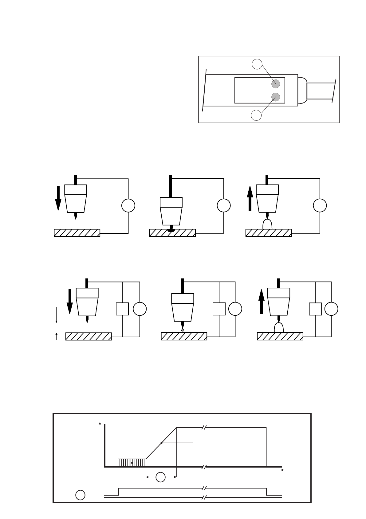
4.3.3Raccordement
Le câble principal de la torche TIG est relié à la prise (6) et la commande de la torche TIG à la prise (5).
L'alimentation en gaz se fait par la prise à raccord rapide (4). La table de soudage ou la pièce à usiner est
reliée à la prise (2). Il est possible de raccorder en outre à la prise (3) une commande à distance manuelle
ou au pied. L'intensité de courant présélectionnée peut être réglée à l'aide d'un potentiomètre incorporé à la
torche.
20
Torche
21
Attention : en cas de raccordement simultané d'une commande à distance manuelle ou au pied et d'une torche à
potentiomètre incorporé de régulation à distance, les deux dispositifs de commande interfèrent. Ne raccorder qu'un
seul dispositif à la fois.
Fig. 1
4.3.4 Amorçage de l'arc
4.3.4.1 Amorçage par contact de la pièce à usiner avec l'électrode
G
Rapprochement Court-circuit Apparition
de la pièce et réchauffement de l'arc
4.3.4.2 Amorçage sans contact par impulsion haute tension
G G
= 2 mm
Rapprochement Amorçage de Apparition
de la pièce l'arc auxiliaire par de l'arc
G
I
les impulsions HT
G G
I I
4.3.5 Fonctionnement à 2 temps
L'actionnement du bouton-poussoir rouge de la torche (Fig. 1 : 20) lance le soudage. Une fois l'amorçage réussi
(par HF ou au contact), le courant de soudage passe du courant de démarrage au courant de soudage choisi dans
le temps de montée programmé.
Dès que la touche est relâchée (Fig. 1 : 20), l'arc s'éteint.
2 temps
Interrupteur du
chalumeau
20
I
Amorçage
Montée du courant
t
10
Page 32
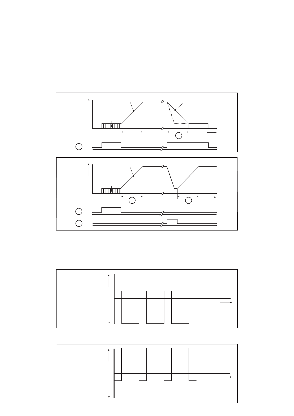
4.3.6 Fonctionnement à 4 temps
L'actionnement du bouton-poussoir rouge de la torche (Fig. 1 : 20) lance le soudage (amorçage par HF ou au
contact). Tant que la touche est enfoncée (Fig. 1 : 20), l'arc brûle selon le courant de démarrage programmé. Le
courant de démarrage peut être réglé de la même façon qu'en mode à 2 temps, mais il ne doit pas descendre en
dessous de 5 A (arc de départ). Une fois que le bouton-poussoir rouge de la torche a été relâché (Fig. 1 : 20), le
courant de l'arc atteint le courant de soudage choisi dans le temps de montée (10) réglé de 0,1 à 10 s. Lorsque le
bouton-poussoir rouge de la torche est à nouveau actionné (Fig. 1 : 20), le courant de l'arc revient au niveau du
courant de coupure (remplissage du cratère final) durant le temps de descente de 0,1 à 10 s. L'arc s'éteint lorsque
le bouton-poussoir rouge est relâché (Fig. 1 : 20).
Sur la poignée de la torche (Fig. 1 : 21) se trouve un deuxième bouton-poussoir vert qui permet, par réglage adéquat
des durées de montée et de descente, de ramener à tout moment le courant de l'arc au niveau du courant de coupure
sans interrompre le soudage. Lorsque le bouton-poussoir vert est relâché (Fig. 1 : 21), le courant de l'arc reprend sa
valeur présélectionnée.
Montée du courant
I
4 temps
Amorçage
Interrupteur du
chalumeau
20
Montée du courant
I
Descente du courant
11
t
Amorçage
Interrupteur du
chalumeau
20
21
10
10
t
4.3.7 Commande de la balance
Lors du soudage de l'aluminium avec électrode tungstène sous gaz inerte et courant alternatif, il se produit un effet
redresseur, c'est-à-dire que les demi-ondes du courant alternatif ne sont pas d'amplitude égale. La commande de
la balance (9) permet de réguler l'effet redresseur de +30 % à -70 %.
La demi-onde négative est plus marquée (morsure importante/nettoyage réduit).
+
Courant d’arc
0
–
La demi-onde positive est plus marquée (morsure faible/nettoyage réduit).
Attention : risque de surcharge thermique de l'électrode.
+
Courant d’arc
0
–
t
t
Page 33
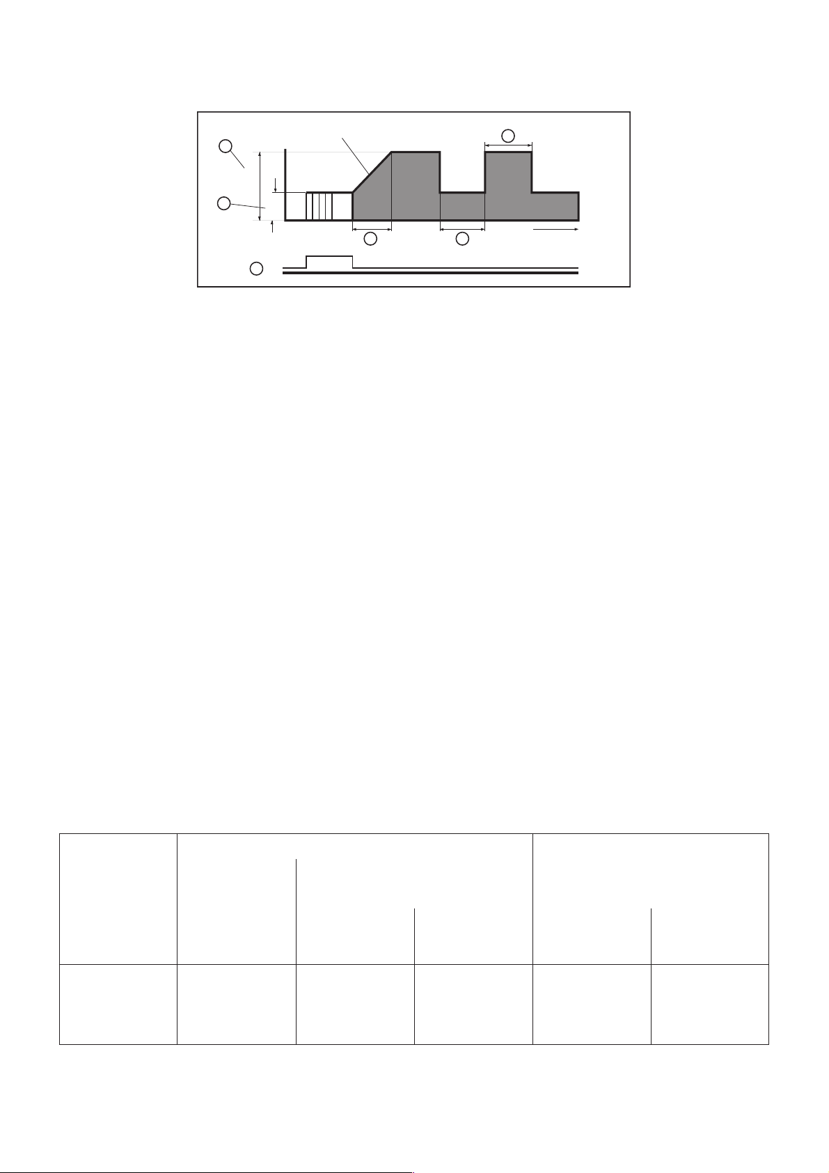
4.3.8 Soudage pulsé
Dans le cas du soudage pulsé, l'arc brûle selon un courant de base réglable en continu (fonction 16 de 5 à 250 A).
Le courant d'impulsion est réglé à l'aide de la fonction 16.
La durée d'impulsion (17) et l'intervalle entre les impulsions (18) sont réglables en continu de 0,1 à 5 s.
Montée du courant
4
Ip
Durée d’impulsion
7
13
Interrupteur du
chalumeau
Ig
10 8
Intervalle entre deux impulsions
20
t
Avantages :
- Soudage de matériaux très minces
- Apport réduit d'énergie lors du soudage d'aciers fortement alliés
- Soudage de matériaux épais avec des matériaux minces
4.3.9 Fonction de démarrage à distance
En mode de démarrage à distance, il est possible de connecter à la prise (3) une commande à distance manuelle
ou au pied. Cette fonction permet à l'utilisateur de lancer le soudage à partir de la commande manuelle ou au pied
et de réguler son intensité (entre le courant de démarrage et le courant de soudage maximal programmés).
Les éléments de commande de la torche TIG sont alors désactivés.
L'utilisateur peut ainsi effectuer des soudages précis sans avoir à guider la torche de la main.
Il est également possible de raccorder une commande à distance avec les fonctions de commande à 2 temps ou 4
temps, avec ou sans amorçage HF, mais le soudage doit être lancé dans ce cas en actionnant le bouton-poussoir
de la torche (Fig. 1 : 20).
5.0 Consignes d'utilisation
Pour amorcer l'arc en toute sécurité et obtenir des résultats irréprochables au soudage, il convient de respecter les
points suivants :
5.1 Types d'électrodes
Pour le soudage TIG avec courant continu, utiliser uniquement des électrodes au thorium :
par exemple WT 20 1,8 - 2,2 % oxyde de thorium, code couleur : rouge
WT 30 2,8 - 3,2 % oxyde de thorium, code couleur : violet
Pour le soudage TIG en courant alternatif, utiliser uniquement des électrodes en tungstène pur :
par exemple électrode en tungstène W, code couleur : vert
5.2 Diamètre des électrodes
Le diamètre des électrodes doit être adapté au courant de l'arc.
Valeurs indicatives : en dessous de 80 A : 1,0 mm de diamètre
70 à 140 A : 1,6 mm de diamètre
130 à 250 A : 2,5 mm de diamètre
AC >220 A : 3,2 mm de diamètre
5.2.1 Intensités maximales admissibles des électrodes TIG
Diamètre Intensité courant de soudage Buse à gaz
courant continu AC avec conden(électrode sur sateur de filtrage
pôle moins) (électrode sur pôle moins)
avec 2% tungstène pur avec 2% Taille Diamètre
thorium
1)
mm A A A mm
1,0 ... 80 ... 30 30 ... 60 4 ... 5 6,5 ... 8
1,6 10 ... 140 30 ... 70 40 ... 100 4 ... 6 6,5 ... 9,5
2,4 20 ... 230 50 ... 110 70 ... 150 6 ... 8 9,5 ... 12,7
3,2 30 ... 310 100 ... 170 130 ... 200 7 ... 8 11,2 ... 12,7
1)
Les valeurs supérieures sont inférieures d'environ 40% pour les électrodes en tungstène pur.
2)
Les valeurs sont supérieures d'environ 50% sans balance.
A noter : les électrodes en tungstène pur ne doivent présenter aucune trace de saleté, d'huile ou de graisse. Les
protéger de ce type d'impuretés.
2)
thorium
Page 34
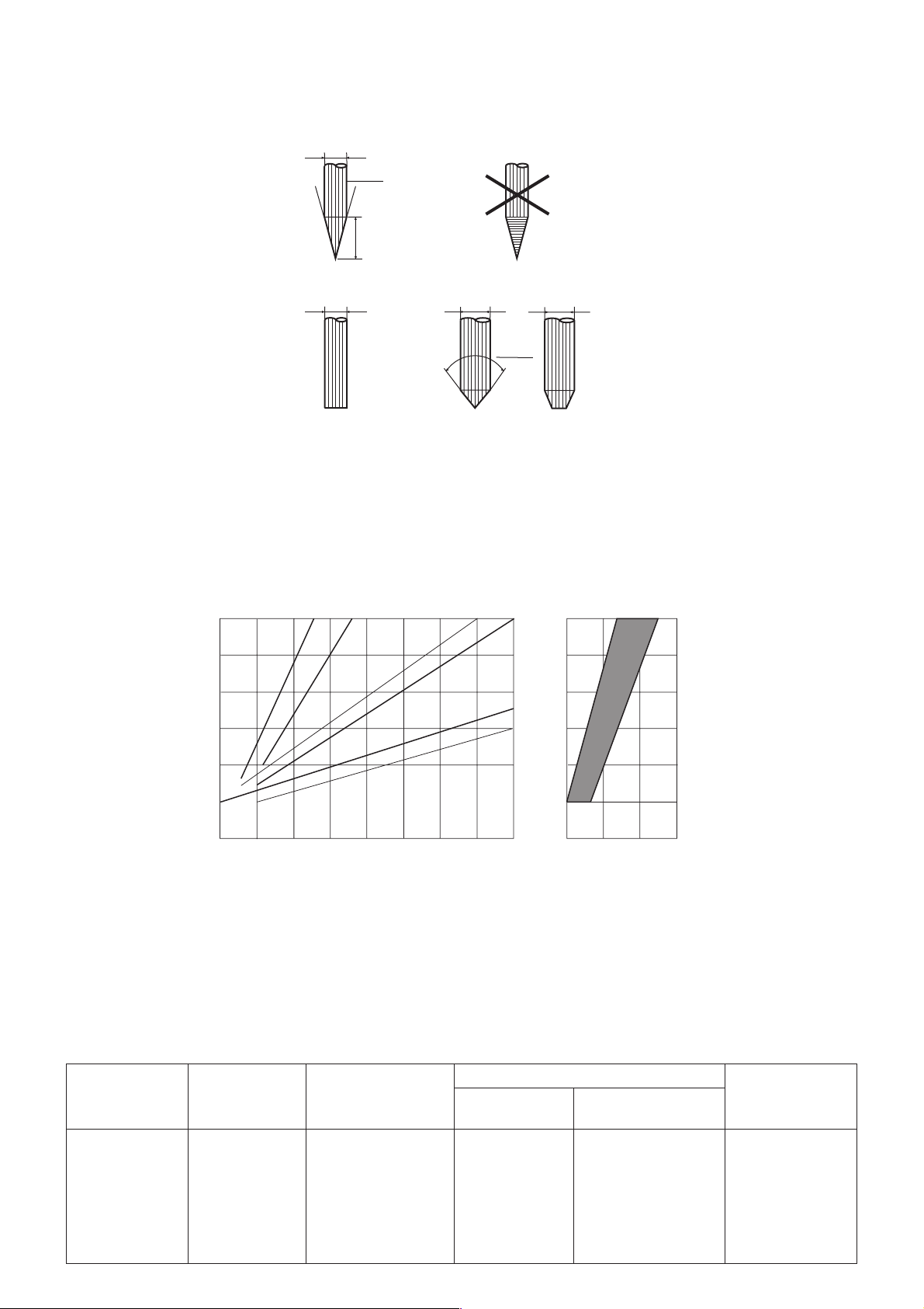
5.3 Meulage
Les électrodes ne doivent être meulées que dans le sens longitudinal en cas de soudage avec du courant continu.
Les électrodes de 1,6 mm de diamètre utilisées avec du courant alternatif ne doivent pas être meulées du tout ; si
D >1,6 mm, elles doivent être taillées en pointe avec l'extrémité cassée. En cas de soudage avec du courant
alternatif, une goutte (calotte) se forme automatiquement sur l'électrode.
Soudage avec courant continu
(pôle moins sur l'électrode)
D
~30°
Longueur ~ 2 x D
L'électrode est généralement taillée
en pointe par meulage dans le sens
de la longueur. Il est rare d'avoir à
polir la surface pour éliminer les
stries.
D
Soudage avec courant alternatif
D
D
A partir d'un certain diamètre, on
~ 90°
meule l'électrode. Une boule (calotte)
se forme à l'extrémité de l'électrode
lors du soudage.
>
D < 1.6 mm
D 1.6 mm
=
5.4 Quantité de gaz
Une quantité trop élevée de gaz peut nuire à l'amorçage. La consommation de gaz inerte et le débit de gaz inerte à
programmer varient selon l'épaisseur de la pièce à usiner et du métal de base.
Consommation d’argon l/min
10
9
Nickel
Aluminium, magnésium, cuivre
Acier, acier chrome-nickel
8
7
6
5
1
23
Epaisseur pièce à usiner mm Diamètre buse à gaz mm
4
5
67
4
85
10 15 20
5.5 Valeurs indicatives d'intensité du courant de soudage en cas de soudage TIG
Acier allié et non allié
Courant continu ; pôle moins sur l'électrode ; position de soudage PA ; joint bord à bord
Epaisseur tôle Forme joint Nombre couches Diamètre Intensité
Electrode Baguette
mm mm mm A
1,0 II 1 1 ou 1,6 1,6 ou 2,0 30 ... 40
2,0 II 1 1,6 ou 2,4 1,6 ou 2,0 70 ... 80
3,0 II 1 ou 2 2,4 2,4 70 ... 90
4,0 II ou V 2 2,4 2,4 70 ... 130
5,0 V 3 2,4 ou 3,2 2,4 ou 3,0 75 ... 130
6,0 V 3 2,4 ou 3,2 2,4 ou 3,0 75 ... 130
Page 35

Aluminium
Courant alternatif ; pôle moins sur l'électrode ; position de soudage PA ; joint bord à bord
Epaisseur tôle Forme joint Nombre couches Diamètre Intensité
Electrode Baguette
mm mm mm A
1,0 II 1 1,6 ou 2,4 2,0 40 ... 50
2,0 II 1 1,6 ou 2,4 3,0 60 ... 80
3,0 II 1 2,4 3,0 110 ... 130
4,0 II 1 ou 2 2,4 ou 3,2 3,0 120 ... 150
5,0 V 1 ou 2 3,2 3,0 150 ... 200
Cuivre
Courant continu ; pôle moins sur l'électrode ; position de soudage PA ; joint bord à bor
Epaisseur tôle Forme joint Nombre couches Diamètre Intensité
Electrode Baguette
mm mm mm A
1,5 II 1 1,6 2,0 90 ... 100
1)
3,0
5,0
1)
II 1 3,2 3,0 150 ... 200
V24,0 4,0 180 ... 300
1)
= préchauffer
A noter : dans les positions de soudage PF et PE, l'intensité du courant de soudage doit être réduite de 10 à 20 %
environ.
6.0 Surcharge / Erreur secteur
6.1 Surcharge
L'appareil TIG 255 AC/DC est équipé de différents dispositifs de protection anti-surcharge. L'appareil s'éteint
automatiquement en cas de dépassement du facteur de marche admissible. Cette coupure de sécurité est indiquée
par le voyant lumineux (11) (le voyant se met à clignoter).
Après un bref temps d'arrêt, l'appareil est à nouveau prêt à l'emploi.
Attention :
Ne pas éteindre l'appareil durant la phase de refroidissement car cela rallongerait considérablement la durée de
refroidissement (le ventilateur est à l'arrêt).
6.2 Erreur secteur
Lorsque la tension d'alimentation est inférieure de 10 % ou plus à la valeur requise, l'appareil s'éteint
automatiquement pour éviter une hausse excessive des courants primaires.
Cette erreur est indiquée par le voyant lumineux (11) (voyant allumé en continu).
Eteindre et remettre sous tension l'appareil pour acquitter ce message d'erreur.
7.0 Indication des dangers
- L'appareil ne doit être utilisé que dans le cadre d'application prévu
(soudage TIG et à électrode).
- Respecter impérativement les consignes de prévention des accidents du travail !
(directive DVV 26 pour l'Allemagne : soudage, découpe et procédés analogues)
- Porter obligatoirement des vêtements de protection appropriés lors du soudage.
- Ne jamais travailler sans bouclier ni gants de protection car le soudage TIG
expose à des rayons UV très intenses.
- L'appareil ne doit être utilisé que dans un endroit sec.
- Le raccorder uniquement à des sources de courant dotées de dispositifs de protection en parfait état de
marche.
- Prudence lors des travaux sur les installations et machines à commande informatisée ou électronique.
L'amorçage à l'arc HF peut perturber le système électronique.
Page 36
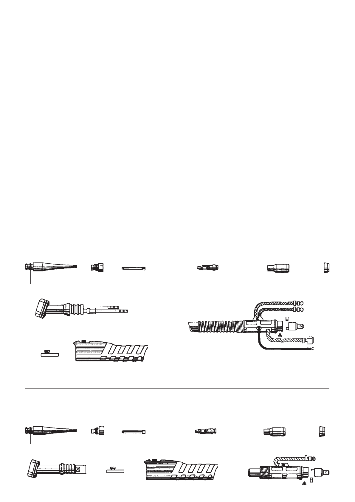
8.0 En cas de panne
8.1 Pas d'amorce en mode TIG
Cause : torche défectueuse
masse défectueuse ou mal raccordée
électrode tungstène sale
8.2 L'appareil travaille uniquement avec un courant minimal
Cause : potentiomètre de la poignée ou commande au pied défectueux.
8.3 Problèmes d'amorçage
Cause : - pas de gaz (ou pas assez)
- électrodes en tungstène mal meulées
- mauvais diamètre d'électrode
- électrodes en tungstène avec traces d'oxydes ou d'impuretés (mauvaises qualités à l'amorçage)
- traces de graisse à la surface de la pièce.
8.4 Le voyant de contrôle [2] est allumé en permanence
Cause : La tension d'alimentation est inférieure de 10 % ou plus à la tension requise. Cela peut être dû par
exemple à un câble d'alimentation secteur très long et de section trop petite. (Chute de tension).
9.0 Chalumeaux SR 18 et SR 26
456 7 8 12
11
2
10
9
Chalumeau SR 18
1
11
Chalumeau SR 26
4
2
56 7
9
10
8
1
12
Page 37

10.0 Liste des pièces de rechange
Rep. Nom de l'article
1 Torche complète - 4 m refroidissement à l'eau 090 201 2036 ●
Torche complète - 8 m refroidissement à l'eau 090 201 2516 ●
Torche compl. - 4 m refroid. eau, régul. à distance 090 201 2044 ●
Torche compl. - 8 m refroid. eau, régul. à distance 090 201 2052 ●
Torche complète - 4 m 090 200 9108 ●
Torche complète - 4 m avec régulateur à distance 090 200 7156 ●
Torche complète - 8 m avec régulateur à distance 090 200 8055 ●
2 Corps de torche 132 717 0500 ●
Corps de torche 132 714 0147 ●
4 Capuchon de torche long 132 712 7230 ●●
5 Capuchon de torche court 132 712 7248 ●●
6 Manchon de serrage 1,0 mm 132 712 7078 ●●
Manchon de serrage 1,6 mm 132 712 7086 ●●
Manchon de serrage 2,4 mm 132 712 7094 ●●
Manchon de serrage 3,2 mm 132 713 5429 ●●
7 Boîtier de manchon de serrage 1,0 mm 132 712 7132 ●●
Boîtier de manchon de serrage 1,6 mm 132 712 7140 ●●
Boîtier de manchon de serrage 2,4 mm 132 712 7159 ●●
Boîtier de manchon de serrage 3,2 mm 132 713 5410 ●●
Code art.
SR 18
SR 26
8 Buse à gaz - céramique Ta. 5 8,0 mm 132 712 7876
Buse à gaz - céramique Ta. 6 9,5 mm 132 712 7175
Buse à gaz - céramique Ta. 7 11,0 mm 132 712 7884
Buse à gaz - céramique Ta. 8 12,5 mm 132 713 5402
9 Double bouton-poussoir rouge/vert 132 717 0488 ●●
10 Enveloppe 132 717 0526 ●●
11 Joint torique 132 712 7892 ●●
12 Bague isolante 132 712 7256 ●●
●
●
●
●
11.0 Liste des pièces de rechange pour appareil de soudage TIG
Désignation No. d'article
●
●
●
●
Platine AC-Drive 4 810 619 8170
Platine NT-AC 4252 810 619 8188
Platine HF-AC 4 810 619 8196
Platine FB-Tren 2 810 619 8200
Platine prise VR 2 810 619 8226
Bobine d'inductance HF 132 719 8234
Unité de commande compl. 810 619 8242
Faisceau de câbles 4 pôles 845 019 8251
Faisceau de câbles 6 pôles 845 019 8260
Faisceau de câbles 10 pôles 845 019 8278
Autotransformateur 132 714 0244
Contacteur B 6-30-10 810 407 3825
Page 38
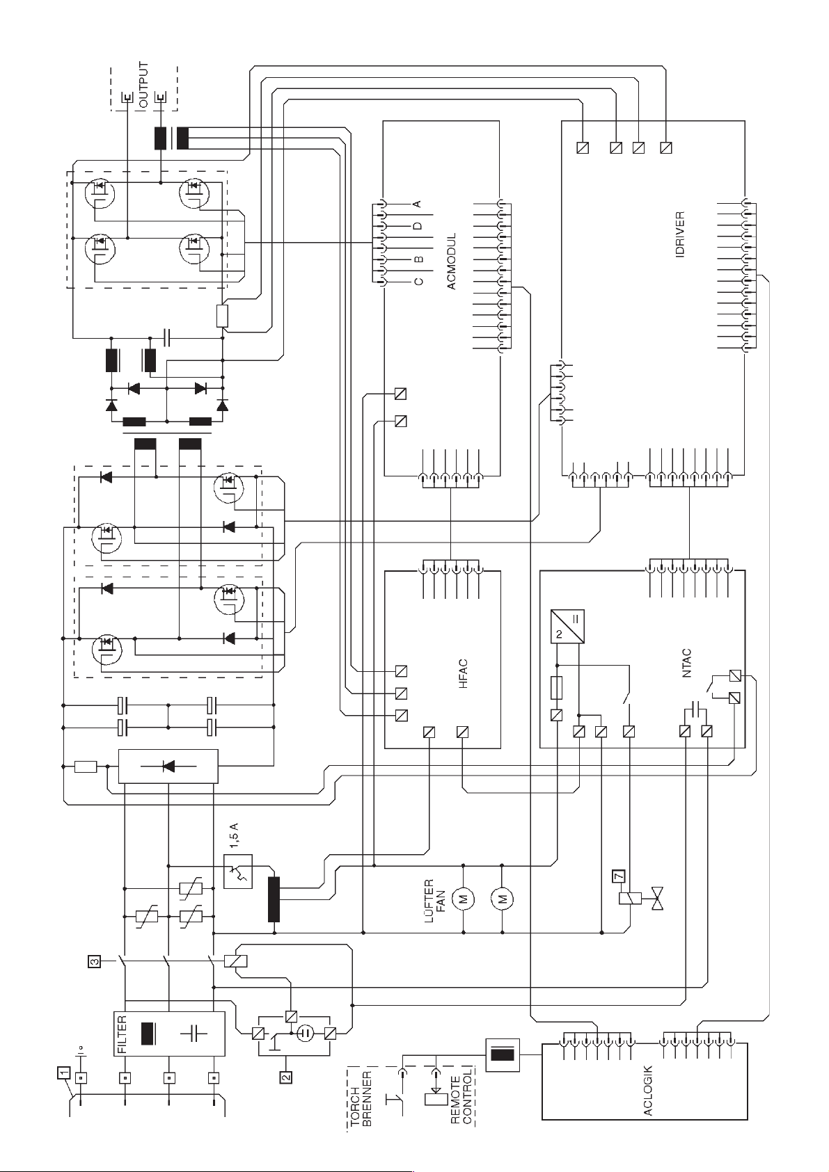
12.0 Schéma électrique12.0 Schaltplan 12.0 Wiring Diagram
Page 39

Page 40

Apartado 53; 7000-171 Evora Codex; (+351) 266 - 74 93 00; (+351) 266 - 74 93 09;
Portugal; BOLAS-Maq. e Ferramentas de Qualidade, S.A.; Rua B, Lotes 8-10-12;
Puerto Rico; J.J. Trading; PMB 409 P.O. Box 4956 Caguas; ; Puerto Rico 00726-4956;
AJAC
(+1) 787 - 739 9693; (+1) 787 - 739 1177; [email protected]
Zona 9-A; Panamá; (+507) 2 23 77 05; (+507) 2 69 18 66; [email protected]
STREET; MEADOWDALE - Germiston; Johannesburg; (+27) 11 - 372 - 96 00;
(+27) 11 - 453-41 63; [email protected]
Domingo; (+1) 809 - 531 50 80; (+1) 809 - 531 53 38;
(+40) 1 - 3 46 31 31; (+40) 1 - 3 46 31 51; [email protected]
(+7) 095 - 198 43 14/198 17 13; (+7) 095 - 198 43 14; [email protected]
(+41 ) 52 - 3 54 34 44; (+41) 52 - 3 54 34 45; [email protected]
(+22) 1 - 823.67.14; (+22) 1 - 823.67.14;
Number One Building; Singapore 408563; (+65) 67 48 28 66; (+65) 67 45 38 72;
(+421) 33 - 641 2522; (+421) 704 - 6 41 25 22; [email protected]
(+386) 61 - 1 68 16 16; [email protected]
263-1 Ipchung-Dong, Chung-Gu; Seoul; (+82) 2 - 22 76 09 14/5; (+82) 2 - 2 78 62 62;
P.O. Box 214 / 130 Front Street; Colombo 11; (+94) 1 - 2 81 71 / 72 / 73;
(+94) 1 - 50 11 83; [email protected]
Santa Lucia; (+1)758 - 452-99 14; (+1)758 - 452-99 15; [email protected]
P.O. Box 169 / Code 113; ; Muscat; (+968) 7 71 09 83; (+968) 7 71 57 55;
(+46) 36 - 16 07 54; [email protected]
(+963) 21 - 2 11 62 45; [email protected]
(+886) 2 - 28 11 08 08; (+886) 2 - 28 16 98 38; [email protected]
Pomprab Bangkok 10100; (+66) 2 - 3 28 11 89; (+66) 2 - 3 28 13 04; [email protected]
(+216) 1 - 25 83 92; (+216) 1 - 35 18 45; [email protected]
(+90) 212 - 2 56 49 50; (+90) 212 - 2 38 98 26; [email protected]
03 151 Kiev; (+380) 44 - 2 45 94 34; (+380) 44 - 2 45 96 57; [email protected]
(+971) 6 - 533 05 51 ; (+971) 6 - 533 73 68; [email protected]
Brandywine Industrial Park; West Chester, PA 19380; (+1) 610 - 4 36 59 00;
(+1) 610 - 4 36 90 72; [email protected]
(+598) 2 - 92 26 06; (+598) 2 - 92 12 69; [email protected]
Caracas 1071; (+58) 212 - 2 37 30 22; (+58) 212 - 2 39 23 65;
Tan Binh District; Ho Chi Minh City; (+84) 8 - 811 74 54; (+84) 8 - 811 63 38;
(+38) 12 15 28 56; (+38) 12 15 24 57; [email protected]
Qatar; Gulf Incon; P.O.Box 4076; ; Doha; (+974) 4 68 35 11; (+974) 4 68 40 65;
Rep. de Panamá; German-Tec (Panamá) S.A.; Via Argentina 46-70; Apartado 342,
Republic of South Africa; Metabo Power Tools SA (Pty.) Ltd.; 165 Van DER BIJL
Republica Dominicana; Agroindustrial Ferretera S.A.; Av. Luperon No. 42; ; Santo
Rumania; S.C. Agent Trade S.R.L.; Splaiul Unirii 235-237; ; 74299 Bucuresti 3;
Russia; OOO ITA-Strojinkom; Uliza Alabjana 3; ; 125057 Moskau;
Schweiz; Metabo (Schweiz) AG; Lindauerstr. 17; ; 8317 Tagelswangen;
Senegal; Ets. M.Y.S.; 12, Rue Tolbiac; B. P. 2389; Dakar;
Singapore; HOMELY HARDWARE PTE LTD; No. 1 Ubi Crescent #01-01;
Slovakia; STAMET Bratislava spol. s.r.o.; M.R. Stefanika 28; ; 90201 Pezinok;
Slovenia; Dilex d.o.o.; Ogrinceva 17; ; 1000 Ljubljana; (+386) 61 - 1 68 16 20;
South Corea; Metabo-Korea Co. Ltd.; Room No. 101, Daesung Building;
Sri Lanka; Hunter + Company Ltd.; General Hardware Importers ;
St. Lucia; Eurotools Int`l Ltd; P.O.Box RB 2484; Rodney Bay, Gros Islet, West Indies;
Sultanate of Oman; Suhail & Saud Bahwan Building Materials L.L.C.;
Sverige; Metabo Sverige AB; Skiffervägen 6; ; 553 03 Jönköping; (+46) 36 - 10 06 60;
Syria; Bachar & Elias Taoutel; Boite Postal 325; ; Aleppo; (+963) 21 - 2 11 80 30;
Taiwan; Taiwan Overseas Trade Co. Ltd.; No. 103 Chung King N. Road Sec. 4; ; Taipei;
Thailand; SSM - Sri Siam Mongkol Co., Ltd; 1570-1576 Krung Kasem RD.; ;
Tunesia; L´Equipment Moderne; 86, Ave. de Carthage; ; 1000 Tunis;
Turkey; Burla A.S.; Voyvoda Cad. 61-65; ; 80003 Karaköy-Istanbul;
Ukraine; Comservice; Ukraian-Russian Joint Venture 2; Narodnogo Opolcheniaya;
United Arab Emirates; Sedana Trading Co; P.O. Box 1919; ; Sharjah;
United States of America; Metabo Corporation; 1231 Wilson Drive / P.O.Box 2287;
Uruguay; Goldfarb S. A.; Rio Negro 1617; P.O. Box 11100; Montevideo;
Venezuela; OLY-COPIA C.A.; 3 ra Transversal Los Ruices ; Edificio Principal II, Piso 4;
Vietnam; HUU HONG MACHINERY CO., LTD.; 157-159 Xuan Hong Street, Ward 12;
(+263) 4 - 77 52 56-9; (+263) 4 - 77 06 95; [email protected]
Yugoslavia; WHM WOBY HAUS MARKT; Brace Ribnikara 55; ; 21000 Novi Sad;
Zimbabwe; Field Technical Sales; 45 Kelvin Road North; Graniteside; Harare;
Ambethan Road, Kharabwadi; Chakan, Tal.: Khed, Dist.-Pune(Pin410 501);
India; Metabo Power Tools PVT Ltd.; Plot No. 40, WMDC Industrial Complex;
Country; Company; Address 1; Address 2; City; Phone; Fax; E-mail
Albania; Extra Industrial Goods; Rl. Fadil Rada 88; ; Tirana; (+355) 42 - 3 30 62;
(+91) 213 - 55 22 03; (+91) 213 - 55 21 61
Indonesia; P.T. Kawan Lama Sejahtera pt; Gedung Kawan Lama Jl. Puri Kencana No. 1;
(+355) 42 - 3 30 62; [email protected]
Algerie; Haddad Equipement Professionel; 98 A, Site du Lycée; ; 16012 Rouiba;
Meruya - Kembangan; Jakarta 11610; (+62) 21 - 5 82 82 82;
(+213) 21 - 85 49 05; (+213) 21 - 85 57 72; [email protected]
(+62) 21 - 5 82 55 88; [email protected]
Argentina; Metabo Argentia S.A.; Teniente Gral. Richieri 4773; ; 1702 - Ciudadela -
Iran; Kalavaran Co. Ltd.; P.O.Box: 11365 - 4653; ; Tehran;
Buenos Aires; (+54) 11 - 44 88 - 9180; (+54) 11 - 44 88 - 39 89; [email protected]
(+98)21 - 67 00 862/67 01 383; (+98)21 - 67 09 427; [email protected]
Australia; Metabo Pty. Ltd; 10 Dalmore Drive; ; Scoresby, Melbourne, Vic. 3179;
Israel; Proter + Cohn Ltd; Technical Supply P.O.Box 33215 / 3; Haatzmaut Road;
(+61) 3 - 97 65 01 99; (+61) 3 - 97 65 01 89; [email protected]
33033 Haifa; (+972) 4 - 8 64 04 69; (+972) 4 - 8 67 18 03; [email protected]
Italia; Carlo Stechel & Figli S.rl; Via Buozzi, 22; ; 20 097 San Donato Milanese (MI);
P.O. Box 5262; Manama; (+973) 71 36 15 / 71 41 74; (+973) 71 26 12;
Bahrain; Bokhammas Establishment; Bldg. 334 Block 321 Old Exhibition Road;
(+39) 02 - 52 77 71; (+39) 02 - 55 60 03 22; [email protected]
Japan; Metabo Japan Co., Ltd.; 5-1024-3, Baigou, Ohme-city; ; Tokyo 198-0063;
Bangladesh; East Bengal Impex; 175, Nawabpur Road (4th floor); ; Dhaka; ;
(+81) 4 - 28 77 05 06; (+81) 4 - 28 77 05 07
Jordan; Newport Trading Agency; P.O.Box 6166 / 151 Hashimi Str.; City Center;
(+880) 2 - 9 56 94 77 / 9 55 04 00;
Belarus; Rosinstrument LTD. INTL. DEPT.; PR-T Skkoriny 107-11; P.O.Box 67; 220023
Amman 111 18; (+962) 6 - 465 56 80; (+962) 6 - 464 54 39; [email protected]
Minsk; (+375) 17 263 99 94; (+375) 17 263 99 94; [email protected]
(+254) 2 - 54 02 70 / - 73; (+254) 2 - 54 00 56; [email protected]
Kenya; Agriquip Agencies (E.A.) Ltd.; Lusaka Rd.; P.O.Box 30 612; Nairobi;
(+32) 2 - 4 67 32 10; (+32) 2 - 4 66 75 28; [email protected]
Belgique; Metabo Belgium; ´t Hofveld 3 - 5; ; 1702 Groot Bijgaarden;
P.O.Box 11429; Jeddah 21453; (+96) 62 - 6 82 04 58; (+96) 62 - 6 91 12 67;
13007 State of Kuwait; (+965) 47 47 137; (+965) 47 47 945;
(+371) 7 38 23 53; (+371) 7 34 94 72; [email protected]
(+371) 7 24 55 62; [email protected]
(+961) 1- 888 288; (+961) 1 - 902 690; [email protected]
(+370) 37 - 31 10 21; [email protected]
(+389) 2 - 364 746; [email protected]
47./b.; ; 1475 Budapest; (+36) 12 - 60 67 12; (+36) 12 - 60 14 23;
56100 Kuala Lumpur; (+60) 3 - 92002966 / 92003966; (+60) 3 - 92007599;
(+356) 21 - 43 54 24; (+356) 21 - 41 73 58; [email protected]
(+222) 525 14 09; [email protected]
(+230) 2 10 74 57; [email protected]
Del. Talpan; C.P. 14090 México, D.F.; (+52) 5 - 555 737 233; (+52) 5 - 555 737 244;
(+373) 2 - 27 77 87; [email protected]
(+212) 2 31 25 06; (+212) 2 - 31 24 62
(+31) 3462 - 6 42 44; (+31) 3462 - 6 35 54; [email protected]
98845 Nouméa; (+687) 27 20 02; (+687) 27 30 94; [email protected]
(+64) 3 - 36 55 931; (+64) 3 - 36 55 932; [email protected]
(+44) 20 - 8992 5727; (+44) 20 - 8992 5335; [email protected]
(+234) 1 - 774 1305; (+234) 1 - 774 1305; [email protected]
(+47) 33 - 44 55 50; [email protected]
(+92) 42 - 7 66 11 88/7 63 06 81; (+92) 42 - 7 66 45 89/7 63 45 95;
(+595) 981 - 43 15 13; (+595) 21 - 33 36 77; [email protected]
(+51) 14 - 4 22 86 31; (+51) 14 - 442 41 30; [email protected]
(+63) 2 - 3 63 01 59; (+63) 2 - 3 61 48 41; [email protected]
(+48) 91 - 5 78 11 95; (+48) 91 - 5 78 07 76; [email protected]
Kingdom of Saudi Arabia; Saudi Industrial Tools Corporation; Madinah Road, Kilo 9;
Kuwait; Naser Moh. Al-Sayer ; Gen. Trading & Contracting Co.; P.O. Box 663 SAFAT;
Latvia; SIA WESS Instrumenti un Tehnika Ltd.; Ganibu dambis 34 a; ; 1005, Riga;
Latvia; Stoller Sia; Krasta 42; ; 1003, Riga; (+371) 7 24 55 61;
Lebanon; SPAN s.a.r.l.; Tools & Equipment Division; P.O. Box 90 - 1218; Beirut;
Lithuania; Technikonas; Savanoriu 286; ; 3042 Kaunas; (+370) 37 - 31 15 53;
Macedonia; MAKWELD D.O.O.; Ilindenska 138; ; 1000 Skopje; (+389) 2 - 363 180;
Magyarorszag; INNOSERVICE-METABO Márkaszerviz Kft.; 1101 Bp. Köbányai út.
Malaysia; Finetools SDN BHD; No. 7 Jalan 1/92C; Batu 3 1/4 Jalan Cheras;
Malta; G + T Imports Limited; Metabo Shop, Birkirkara By-Pass; ; Iklin BZN 11;
Mauritanie; S.T.A.F; B.P.: 40246; ; Nouakchott; (+222) 525 33 85;
Mauritius; Dema - Supplies Ltd.; 2A Deschartres Street; ; Port Louis; (+230) 2 12 64 05;
Mexico; Uniservicio Ferretero S.A de C.V.; Matamoros No. 237 Col. la Joya ;
Moldova; BRISAR-COM S.R.L.; str. Sciusev, 78; ; 2012 Chisinau; (+373) 2 - 22 24 50;
Morocco; Sté Yyes Rouger; 20 Bd. Ibn Tachfine; ; 20300 Casablanca;
Nederland; Metabo Nederland b.v.; Postbus 180; ; 3620 AD Breukelen;
New Caledonia; Ets. Szemmelveisz; 3, Rue Fernand Forest; Boite Postale 668;
New Zealand; Tooline Ltd.; 49 A Sonter Road; P.O. Box 797; Christchurch;
Nigeria; Mathani Brothers Ltd.; 60 Park View North Action; ; London W3 OPT;
Nigeria; Bestline Nigeria Ltd.; 15, Hospital Road; Olodi Apapa; Lagos ;
Norway; Metabo Norge AS; Postboks 1296; ; 3205 Sandefjord; (+47) 33 - 44 55 55;
Pakistan; Mercantile Company; Mercantile House 44-Brandreth Road; ; Lahore;
Paraguai; Taguato S.A.; Avda.Gra.Santos No. 1948/Tte. Garay; ; Asuncion;
Peru; Sucesion Carlos Kaufmann; Juan de Arona 760, Of.102 ; ; San Isidro ;
Philippines; Mach Tools Inc.; 185 A & B del Monte Avenue; ; Manresa, Quezon City;
Cochabamba; (+591) 4 - 425 10 62 ; (+591) 4 - 425 10 61; [email protected]
(+387) 51 - 302 718; (+387) 51 - 785 708; [email protected]
Diadema - Sao Paulo - Cep 09911-630; (+55) 11 - 40 51 - 25 11;
(+55) 11 - 4056 - 4152; [email protected]
(+359) 2 - 9 78 58 90; (+359) 2 - 9 78 86 04; [email protected]
Ontario, L4Z 1 W6; (+1) 905 - 755 06 08; (+1) 905 - 755 06 11; [email protected]
(+420) 202 - 80 44 55; (+420) 202 - 80 44 56; [email protected]
(+56) 2 - 6 99 04 85; [email protected]
Bogota; (+57) 1 - 346 28 99; (+57) 1 - 346 29 16; [email protected]
San José; (+506) 2 32 91 11; (+506) 2 32 93 53; [email protected]
(+385) 1 - 24 06 000; [email protected]
1641 Lefkosia, Cyprus; (+357) 22 - 34 95 77; (+357) 22 - 34 93 94;
(+45) 43 - 31 34 01; [email protected]
0180 - 3 00 04 16; 0180 - 300 04 17; [email protected]
(+593) 4 - 25 43 00; (+593) 4 - 25 49 39; [email protected]
(+372) 620 11 12; [email protected]
(Cairo); (+20) 2 - 3 03 02 51 / 3 47 89 17; (+20) 2 - 3 02 58 96;
Cuscatancingo; San Salvador; (+503) 2 - 38 47 65; (+503) 2 86 52 36;
28660 Boadilla del Monte (Madrid); (+34) 91 - 6 32 47 40; (+34) 91 - 6 32 41 47;
(+251) 1- 52 68 19; (+251) 1-53 53 85; [email protected]
(+358) 9 - 41 58 15; (+358) 9 - 41 58 22 07; [email protected]
(+33) 1 - 30 64 55 30; (+33) 1 - 30 44 37 68; [email protected]
P.O. Box 1783; Accra; (+233) 21 - 66 39 94; (+233) 21 - 78 02 90;
Southampton / SO 16 OYT; (+44) 2380 - 73 20 00; (+44) 2380 - 74 75 00;
Bolivia; Agencias Generales S.A.; Casilla de Correo 530 Avda. San Martin S-0253; ;
Bosnia and Herzegovina; Agrarkombinat; Majevicka 1; ; Banja Luka;
Brazil; Metabo do Brasil Ltda.; Rua Guicurus 306 - Vila Conceicao; ;
Bulgariia; KIROV Ltd.; Gara Iskar; Porutschik-Nedeltscho-Bontschev-Str.10; 1582 Sofia;
Canada; Metabo Canada Inc.; 190 Britannia Road East; Unit No. 12; Mississauga,
Ceska Republica; Metabo s.r.o; Kralovicka 544; ; 250 01 Brandys nad Labem;
Chile; Nordchil S.A.; San Diego 895; ; Santiago de Chile; (+56) 2 - 6 72 29 11;
Colombia; EUROTOOLS Ltda.; Avenida Caracas No. 74-25; Edificio Ferricentros-4 Piso;
Costa Rica; Capris S.A.; Frente la Imprenta Nacional, La Uruca; P.O. Box 7-2400;
Croatia; CROM d.o.o.; Obrtnicka 2; ; 10000 Zagreb; (+385) 1 - 24 06 246;
Cyprus; Med Marketing Ltd. (eurotools); P.O. Box 27017; 17, Digenis Akritas Ave;
Danmark; Metabo Danmark A/S; Helgeshoj Allé 12; ; 2630 Tastrup; (+45) 43 - 31 34 00;
Deutschland; Metabowerke GmbH ; Walter-Rauch-Str. 1; ; 72622 Nuertingen;
Ecuador; Maquinarias Henriquez C.A.; P.O.Box 09 - 01 - 43 61; ; Guayaquil;
Eestlane; A/S MECRO; Peterburi tee 44; ; 11415 Tallinn; (+372) 620 11 11;
Egypt; Modern Machines + Materials Co.; 18 Geziret El Arab. St.; ; Mohandseen Giza
El Salvador; Metabo S.A. de C.V.; Colonia Santa Clara, Pasaje C No. 20;
Espana; Herramientas Metabo S.A.; Polígono Ind. Prado del Espino; C/Forjadores, 12;
Ethiopia; SUTCO Pvt. Ltd. Co.; W. 19 K. 50 HN new, Wollo Sefer; ; Addis Ababa;
Finland; Wihuri Oy Autola; P.O. Box 58 Manttaalitie 9; ; 01511 Vantaa;
France; Metabo S.A.; Z.A.C. 2, Avenue des Ormeaux; ; 78180 Montigny-le-Bretonneux;
Ghana; Emmnock Powercom Ltd.; Knutsford. Avenue opp. Morocco House;
01009; (+502) 3 32 47 24; (+502) 3 32 47 81; [email protected]
Great Britain; Metabo (UK) Ltd.; 25 Majestic Road ; Nursling Industrial Estate;
Guatemala; Almacen la Palma S.A.; 2a Calle 4-38, Zona 9; ; Guatemala Ciudad,
Hellas; Fedon N. Economides + Co.; Prigiponison Street 27; ; 11363 Athens;
(+689) 41 24 00; [email protected]
Polska; Metabo Polska Sp. z o.o.; Gdynska 28; ; 73-110 Stargard Szczecinski;
Polynésie francaise; Ets Dieumégard Import; BP 14 132 Arue; ; Tahiti; (+689) 42 32 38;
(+30) 1 - 8 21 60 83 / 8 84 29 66; (+30) 1 - 8 82 56 00; [email protected]
Sha Wan Road; Kowloon / Hong Kong; (+852) 29 26 22 00; (+852) 28 82 19 78;
(+354) 57 57 605; [email protected]
Hong Kong; Jebsen & Co. Ltd. ; 9/F, Jebsen Motor Group Building; 924-926 Cheung
Iceland; Fossberg Ltd; Sudurlandsbraut 14; ; 108 Reykjavik; (+354) 57 57 600;
 Loading...