

Page 1

W 7-100
W 7-115
W 7-125
W 7-115 Quick
W 7-125 Quick
W 8-125
W 9-115
W 9-125
W 9-125 Quick
W 10-125
W 10-125 Quick
W 10-150 Quick
WE 9-125 Quick
WE 14-125 Plus
Made in Germany
WE 14-150 Plus
WE 14-150 Quick
WP 7-115 Quick
WP 7-125 Quick
WPS 7-115 Quick
WPS 7-125 Quick
WQ 125 SP
PRC . . . . . . . . . . . . . . . . . . . . . . . 5
Korea . . . . . . . . . . . . . . . . . . . . . 13
Instruction for use . . . . . . . . . . . . 21
170 24 9970 - 0305
Page 2
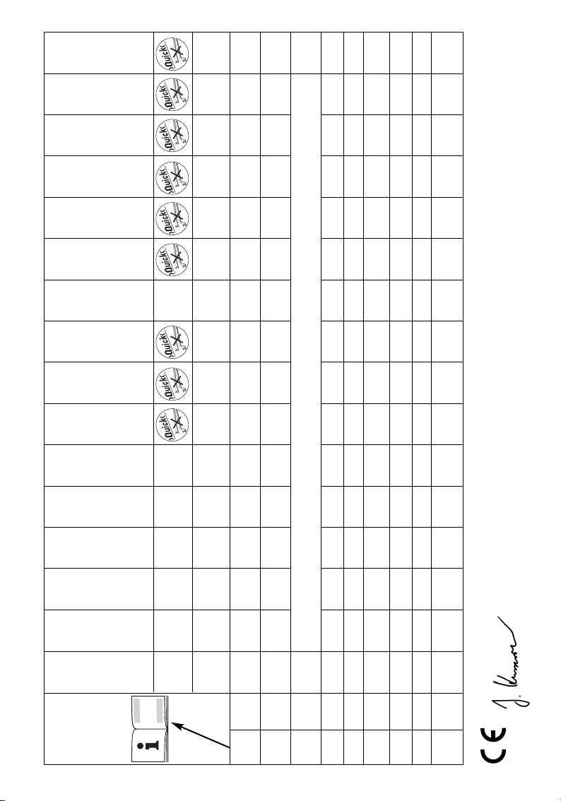
WE 14-150 Quick
16
TC
electronic
WE 14-150 Plus
WE 14-125 Plus
WE 9-125 Quick
W 10-150 Quick
W 10-125 Quick,
WQ 125 SP
W 10-125
W 9-125 Quick
W 7-125 Quick,
WP 7-125 Quick,
WPS 7-125 Quick
W 7-115 Quick,
WP 7-115 Quick,
WPS 7-115 Quick
W 9-125
VTC
electronic
VTC
electronic
VC
electronic
10.000 10.500 9.000
5/8"-11 UNC
2
W 9-115
W 8-125
W 7-125
W 7-115
W 7-100
–––––– –
––––––––––––
(in) (4) (4 1/2) (5) (5) (4 1/2) (5) (4 1/2) (5) (5) (5) (5) (6) (5) (5) (6) (6)
mm 100 115 125 125 115 125 115 125 125 125 125 150 125 125 150 150
max
D
n /min 10.000 10.000 10.000 10.000 10.000 10.000 10.000 10.000 10.000 10.000 10.000 9.000 3.000- 7.000- 6.000- 9.000
M M 10 M 14
W 750 750 750 850 950 950 750 750 990 1.010 1.010 1.010 900 1.400 1.400 1.400
1
P
460 460 460 520 570 570 460 460 560 600 600 600 510 800 800 800
W
2
P
5555555555555555
) (15) (15) (15) (15) (15) (15) (15) (15) (15) (15) (15) (15) (15) (15) (15) (15)
2
2
m/s
(ft/s
hw
a
dB(A) 84 84 84 86 86 86 84 84 86 86 86 86 84 85 85 85
L
pA
dB(A) 97 97 97 99 99 99 97 97 99 99 99 99 97 – – –
L
WA
© 2005 Metabowerke GmbH, Postfach 1229, D-72602 Nürtingen, Germany
Jürgen Kusserow, Geschäftsleitung
EN 50144, 98/37/EG, 89/336/EWG.
(lbs) (4.0) (4.0) (4.0) (4.0) (4.0) (4.0) (4.0) (4.0) (4.0) (4.0) (4.0) (4.0) (4.2) (4.2) (4.2) (4.2)
m kg 1,8 1,8 1,8 1,8 1,8 1,8 1,8 1,8 1,8 1,8 1,8 1,8 1,9 1,9 1,9 1,9
Page 3
WP...
WPS...
9
8
1
2
3
7
6
4
5
10
3
11
12 13
Page 4
a
b
c
d
g
k l
e f f f
h i j
m
n
4
Page 5
1
2
3
4
5
6
7
8
9.1
9.2
9.3
2
1
2
3
9
80m/s
4
5
10
10.1
10.2
10.3
11
12
13
13.1
13.2
13.3
13.4
13.5
14
15
16
5
Page 6
3
10
.45m/s
30
5
4
GFCI
3
10
max. 80 mm
30mA FI
6
Page 7
RPM
*
1*
2
3*
4
5
6*
7*
8
9
10*
11*
12*
13*
5
6
ᖙ乏ᤶᤳണ⸈㺖ⱘᶘDŽབᵰᴎ఼ⱘ
ᶘᤳണˈ⽕ℶ᪡䆹ᴎ఼DŽ
䰘ᏺޣᤃᶘ˄ḍկ䋻㣗ೈ⹂ᅮ˅˖
Փᣕ㓁᪡ࡴ㟦䗖DŽ
䰘ᏺޣᤃᶘ˄ḍկ䋻㣗ೈ⹂ᅮ˅˖
ᶘ/ޣᤃᶘ
*
7
Page 8
VTC TC
6
12 11
10
4
VTC TC
6
5
7
8
VC/VTC/TC
VC/VTC
VC/VTC/TC
1
WWE
1
9
WP WPS
8
9
9
WP
8
9
1
0
I
8
Page 9
VTC/TC
6
8
7
9
2
9.1
9
10
10
10
8
8m
5/16"
13 12
11
11
11
5
2
2
11
/
10.2
10.1
(10)
9
Page 10
13
12
12
12
B
A
12
13
/
10
A
B
10
13
11
11
VTC TC
6
12
4
b
c
d
e
f
g
h
i
j
k
l
m
n
a
12
13
12
1
2
3
10.3
10
13.1
Page 11
12.1
13.2
12.2
i
13
b5
b
12.4
4
10
12.3
4
f 22mmAF
7/8"
10
13.4
13.3
13.5
11
Page 12
0.5 1cm/0.2" 0.4"
11
m
EN 50144
A
L
L
a
hw
pA
WA
15
2
D
n
M
P
P
1
max
14
/
14
15
6
12 11
12
11
12
n
12
Page 13
1
2
3
4
5
6
7
8
9
10
10.1
10.2
10.3
11
12
13
13.1
13.2
13.3
13.4
13.5
14
15
16
3
4
1
2
13
Page 14
max. 80 mm
3
10
14
Page 15
5
*
6
15
Page 16
8
1
0
I
7
16
Page 17
10
10
10.1
11
10.2
9
10
17
Page 18
12
12
B
A
12
13
10.3
11
12
13
(12)
18
Page 19
b
10
13.1
1
2
3
13.2
13.4
13.5
13.3
19
Page 20
14
16
20
15
Page 21
Instruction for use
Dear Customer,
Many thanks for the confidence you have shown in us with the purchase of your new Metabo power tool.
Every Metabo power tool is carefully tested and is subjected to the strict quality controls of the Metabo
Quality Assurance section. However, the service life of any power tool is to a great degree dependent on
yourself as the user. Please read and understand the information contained in these Operating
Instructions and the accompanying documents. The more care you exercise in handling your Metabo
power tool, the longer will be the reliable service it provides for you.
Contents
1 Declaration of Compliance
2 Proper Use
3 General Safety Rules
4 Specific Safety Rules
5 Functional Description
6 Special Product Features
7 Assembly, Initial Use
8 Operation, Switching On/Off
9 Operation, Setting Speed
(depending on equipment)
10 Operation, Fitting Tools
10.1 Fitting cutting and grinding discs
10.2 Securing/releasing the Quick
clamping nut (depending on equipment)
10.3 Securing/releasing the clamping nut
(depending on equipment)
11 Maintenance
12 Troubleshooting
13 Accessories
13.1 Removing the wheel guard
13.2 Fitting the hand guard
13.3 Fitting the backing pad and sanding
discs
13.4 Fitting the wire brush
13.5 Fitting the cup-grinding wheel with
wheel guard
14 Repairs
15 Environmental Protection
16 Technical Specifications
1 Declaration of Compliance
On our own responsibility, we hereby declare that
this product complies with the standards or
standard-setting documents listed on page 2.
2 Proper Use
Equipped with the appropriate accessories,
Metabo angle grinders are suitable for cutting,
grinding, sanding with a backing pad and
brushing metal, concrete, stone and similar
materials in dry operating conditions.
Saw discs, saw chains or similar parts must not
be used under any circumstances.
The operator bears sole responsibility for any
damage caused by inappropriate use.
The generally recognised accident prevention
regulations and the accompanying Safety
Instructions must be observed.
3 General Safety Rules
Read and understand all instructions.
Failure to follow all instructions listed
below and in the red booklet may result
in electric shock, fire and/or serious
personal injury.
SAVE THESE INSTRUCTIONS.
Keep all of the documents supplied with the tool
in a safe place and pass them on to the new
owner if you part with the tool.
4 Specific Safety Rules
Always use proper guard with grinding wheel.
A guard protects operator from broken wheel
fragments.
Accessories must be rated for at least the
speed recommended on the tool warning
label.
Wheels and other accessories running over rated
speed can fly apart and cause injury. Use at least
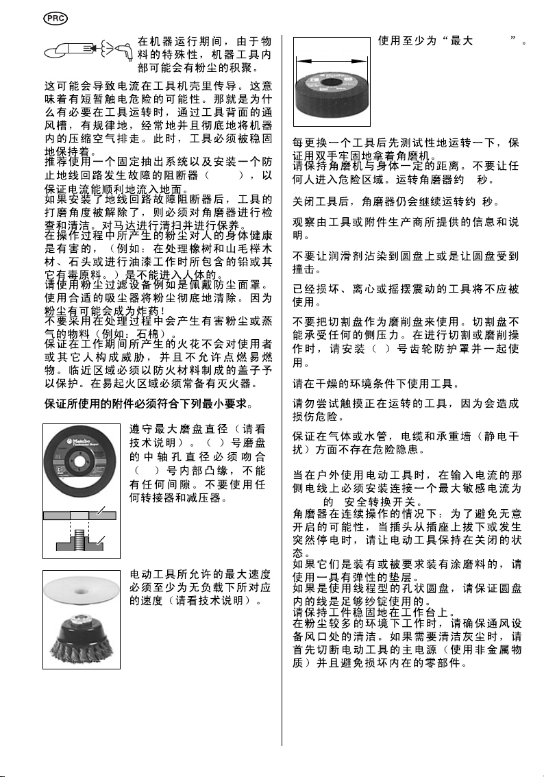
"max. 80 m/s".
Hold tool by insulated gripping surfaces when
performing an operation where the cutting
tool may contact hidden wiring or its own
cord.
Contact with a"live" wire will make exposed metal
parts of the tool "live" and shock the operator.
Pay particular attention to the
parts of the text marked with this
symbol for your own safety and
the protection of your power tool.
21
Page 22
Always wear eye goggles and hearing protection.
max. 80 mm
3
10
Use other available protective equipment such as
protective gloves, suitable protective work
clothing and helmet.
Before using the angle grinder, install the side
handle (5) and always keep both hands on the
tool at all times during use.
transfer of electrical energy onto the machine
housing. This can mean a temporary danger of
electric shocks. This is why it is necessary when
the machine is running to blow compressed air
through the rear ventilation slots of the machine
regularly, frequently and thoroughly. Here, the
machine must be held firmly.
It is recommended to use a stationary extraction
system and to place a ground fault circuit
interrupter (GFCI) downstream.
If the angle grinder is deactivated by the GFCI
circuit interrupter, the angle grinder must be
checked and cleaned. Cleaning the motor, see
Maintenance.
The dust generated during operation is often
injurious to health (e.g. when processing oak and
beech woods, stone or paintwork which may
contain lead or other harmful materials). This dust
must not be allowed to penetrate the body. Use
dust-extraction equipment as well as wearing a
suitable dust mask.
Remove any accumulations of dust thoroughly,
using a suitable vacuum cleaner.
Dust can be explosive!
Materials which generate hazardous dusts or
vapours during processing (e.g. asbestos) should
not be used.
Ensure that sparks produced during work do not
constitute a risk to the user or other personnel
and are not able to ignite inflammable
substances. Endangered areas must be protected
with flame-resistant covers. Make sure that firerisk areas are always provided with suitable fire
extinguishers.
Ensure that the accessories used always fulfil
the following minimum requirements.
22
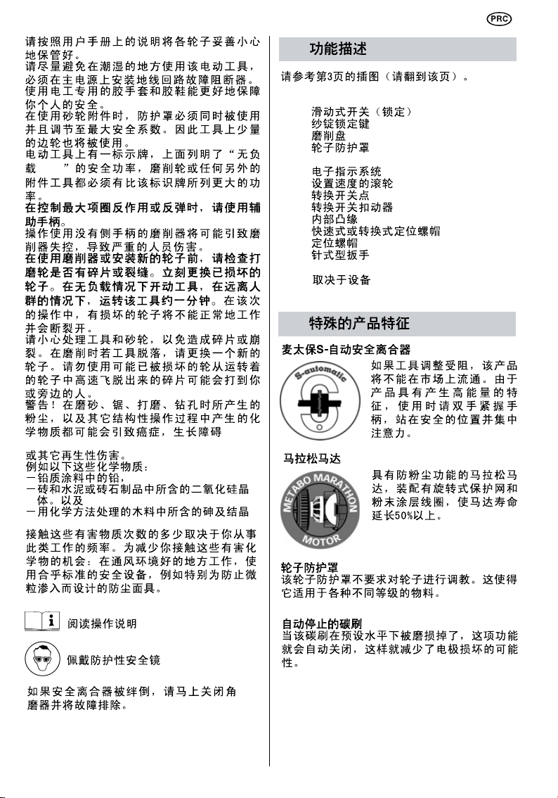
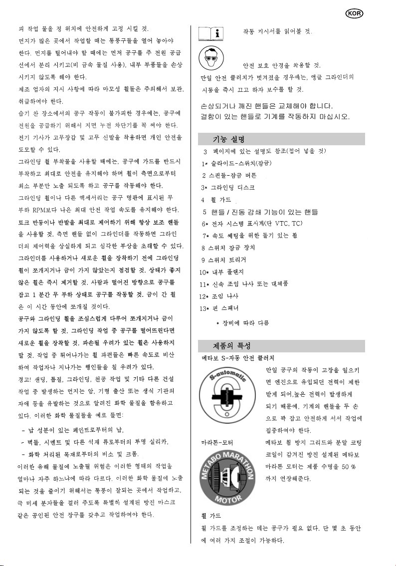
The permitted speed n
correspond at least to the
no-load speed for the power
tool (please see Technical
Specifications).
During machining, of metals
in particular, conductive dust
can form deposits inside the
machine. This can lead to the
Carry out a test run after every tool change,
ensuring that you are holding the angle grinder
firmly with both hands.
Hold the angle grinder away from your body.
Ensure that there is no-one present in the area at
risk. Run the angle grinder for approximately
30 seconds.
The angle grinder runs on for approx. 5 seconds
after switch-off.
Observe the information and instructions provided
by the tool or accessory manufacturer.
Do not contaminate discs with grease or subject
them to impact.
Damaged, eccentric or vibrating tools should not
be used.
Never use cutting discs for grinding purposes.
Cutting discs must not be subjected to any lateral
pressure. During cutting or grinding operation,
always work with the wheel guard (4) fitted.
Use tools in dry operating conditions only.
Do not attempt to touch the moving tool - risk of
injury.
Ensure that no damage is caused to gas or water
pipes, electrical cables and weight-bearing walls
(statics).
When using the power tool outdoors, an FI safety
switch with a maximum tripping current of 30 mA
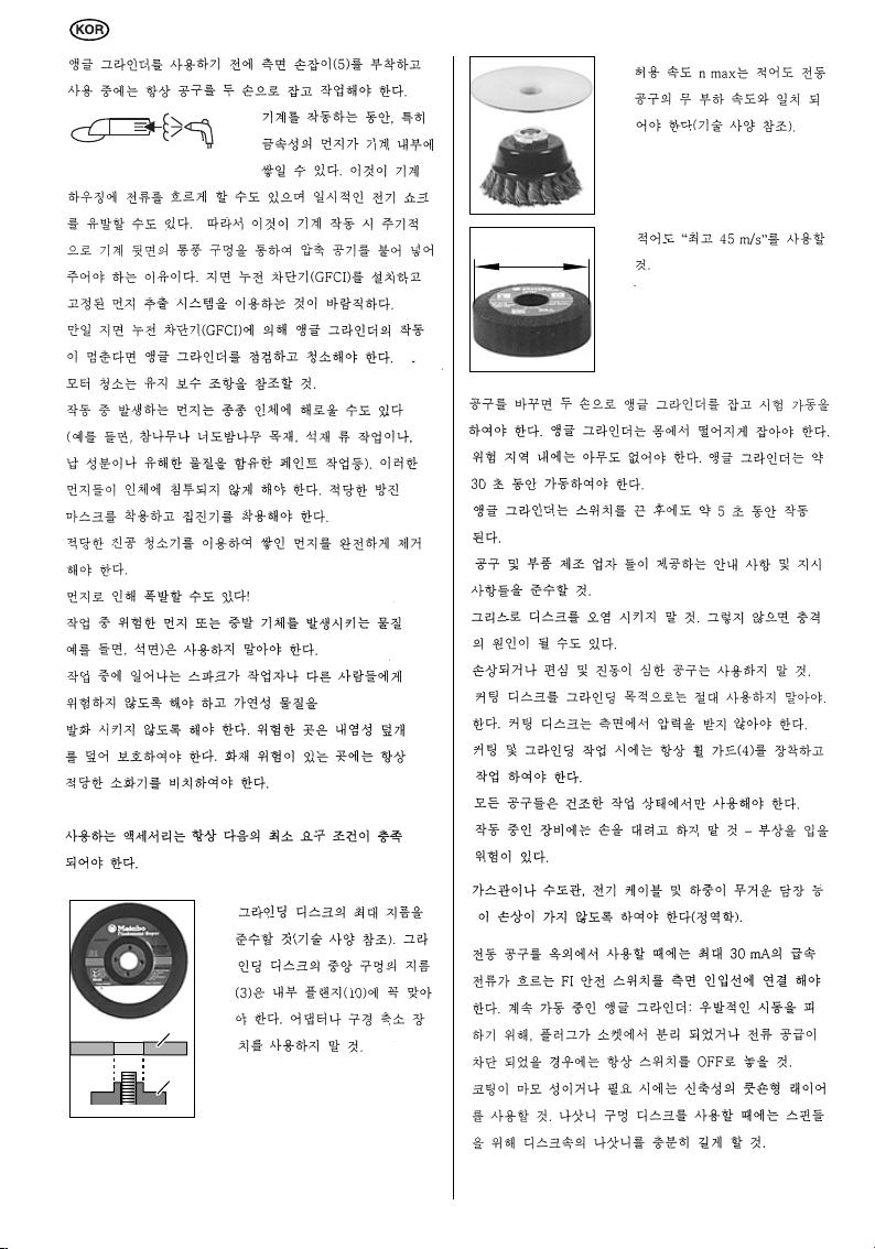
Respect the maximum
grinding-disc diameter (please
see Technical Specifications).
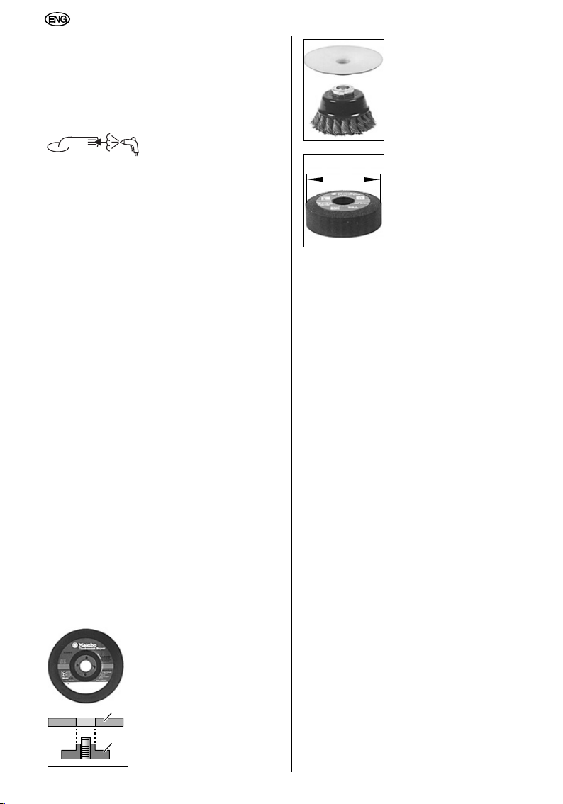
The diameter of the central
hole in the grinding disc (3)
must fit the inner flange (10)
without any play. Do not use
any adapters or reducers.
must be connected on the incoming line side.
Angle grinder in continuous operation: To avoid
the possibility of unintentional start-up: always
turn off the switch when the plug is removed from
the socket or if an interruption to the power supply
has occurred.
Use elastic cushioning layers, if they are provided
with the coated abrasive and if they are called for.
If using threaded hole discs, ensure that the
thread in the disc is long enough for the
spindle.
Use at least "max. 45 m/s".
max
must
Page 23
Hold the work piece securely in place.
Ensure that ventilation openings are kept clear
when working in dusty conditions. If it should
become necessary to clear dust, first disconnect
the tool from the mains supply (use non metallic
objects) and avoid damaging internal parts.
Abrasive wheels shall be stored and handled with
care in accordance with manufacturer`s
instructions.
If operating the power tool in damp locations is
unavoidable, a Ground Fault Circuit Interrupter
must be used to supply the power to your tool.
Electrician’s rubber gloves and footwear will
further enhance your personal safety.
When using grinding wheel attachments, the
guard must always be attached to the tool and
positioned for maximum safety, so the least
amount of wheel is exposed from the side the tool
is being operated.
Grinding wheels or any other accessory must
have a maximum safe operation speed greater
than the “no load RPM” marked on the tool´s
nameplate.
Always use auxiliary handle for maximum
control over torque reaction or kick-back.
Operation of the grinder without the side handle
could cause loss of control of the grinder,
resulting in possible serious personal injury.
Before using a grinder or installing a new
wheel, inspect the grinding wheel for chips
and cracks. Remove bad wheels immediately.
Run the tool at no load for one minute,
holding the tool in the direction away from
people. Wheels with flaws will normaly break
apart during this time.
Carefully handle both the tool and individual
grinding wheels to avoid chipping or cracking.
Install a new wheel if tool is dropped while
grinding. Do not use a wheel that may be
damaged. Fragments from a wheel that bursts
during operation will fly away at great velocity
possibly striking you or bystanders.
Warning! Some dust created by power sanding,
sawing, grinding, drilling, and other construction
activities contains chemicals known to cause
cancer, birth defects or other reproductive harm.
Some examples of these chemicals are:
– Lead from lead-based paints,
– Crystalline silica from bricks and cement and
other masonry products, and
– Arsenic and cromium from chemically treated
lumber.
Your risk from these exposures varies, depending
on how often you do this type of work. To reduce
your exposure to these chemicals: work in a well
ventilated area, and work with approved safety
equipment, such as dust masks that are specially
designed to filter out microscopic particles.
Read operation instructions
Wear safety goggles
If the safety clutch is tripped, switch the angle
grinder off immediately and remedy the fault.
A damaged or cracked side handle must be
replaced. Never operate a machine with a
defective side handle.
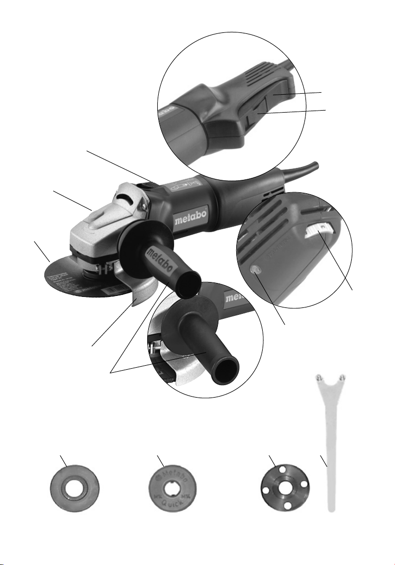
5 Functional Description
Refer to illustrations on page 3
(Please fold out).
1* Slide-switch (locking)
2 Spindle-lock button
3* Grinding disc
4 Wheel guard
5* Side handle / Side handle with vibration
damping
6* Electronic system indicator (VTC, TC only)
7* Knurled wheel for setting speed (VC, VTC)
8 Switch loc
9 Switch trigger
10* Inner flange
11* Quick clamping nut
or alternative
12* Clamping nut with
13* Pin spanner
*depending on equipment
6 Special Product Features
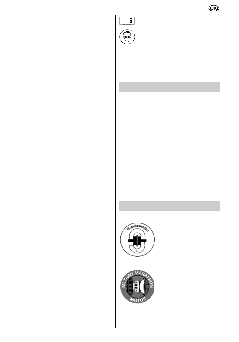
Metabo S-automatic safety clutch
If the tooling jams, the power
flow to the engine will be
restricted. Because of the high
power which then arises,
always hold the machine with
both hands on the handles,
stand safely, and concentrate
on your work.
Marathon-Motor
The dust-protected Metabo
Marathon-Motor with its
Metabo winding-protection grid
and powder-coated coil
winding ensures up to 50%
longer service life.
Wheel guard
The wheel guard requires no tools for adjustment.
This allows it to be adjusted for a variety of
applications in a matter of seconds.
23
Page 24
Auto-stop carbon brushes
1
0
I
When the auto-stop carbon brushes wear down to
a predetermined level the power tool is
automatically switched off, thus ruling out the
possibility of damage to the armature.
Additional side handle with vibration damping
(depending on scope of supply):
For comfortable work in continuous operation.
VC/VTC/TC electronic speed-control system
(depending on equipment)
This electronic control system ensures the correct
grinding speed for the relevant material (VC/VTC)
and maintains close to a constant speed, even
under load (VC/VTC/TC).
The Vario-Tacho-Constamatic (VTC)/ TachoConstamatic (TC) electronic system also features
starting-current limitation, electronicallycontrolled, smooth start-up, coil-temperature
monitoring and an electronic restart safety device.
Refer to the Technical Specifications for the
equipment level for your specific angle grinder.
7 Assembly, Initial Use
Before initial use, check that the mains
voltage and mains frequency stated on
the rating plate match the figures for
your own mains supply.
Fit side-handle
For reasons of safety, always fit the
side handle (5) to the right or left-hand
side of the angle grinder before
commencing work.
Fit wheel guard
(before working with the grinding disc)
With VTC, TC electronic system (depending on
equipment):
The red electronic system indicator (6) lights up
briefly when the mains connection is made, thus
indicating standby mode.
8 Operation, Switching On/Off
Always guide the machine with both
hands!
First switch on, then apply the tool to
the work piece!
It must be avoided that the machine
draws in additional dust and shavings.
When switching the machine on and off,
keep it away from dust deposits.
After switching off the machine, only
place it down when the motor has come
to a standstill.
In the case of VTC, TC electronic control:
the red electronic signal indicator (6) comes on
briefly when the machine is switched on.
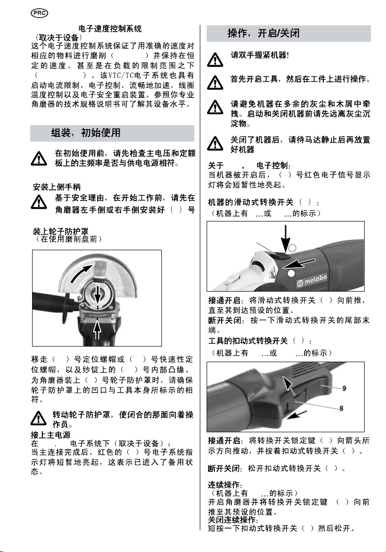
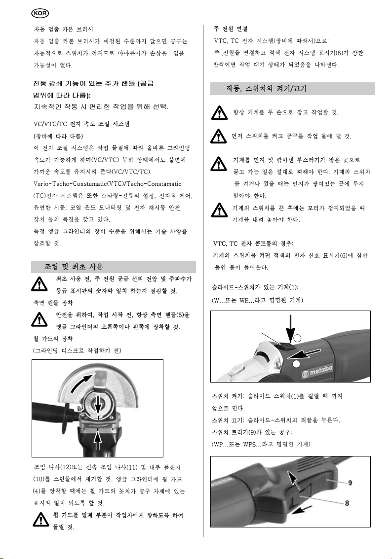
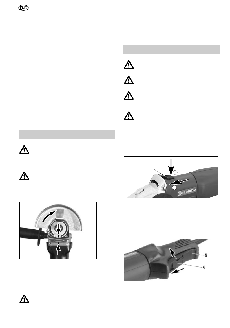
Machines with slide-switch (1):
(Machines with the designation W... or WE...)
Switching on: slide the slide-switch (1) forward
until it engages.
Switching off: press the rear end of the slideswitch.
Tools with switch trigger (9):
(Machines with the designation WP... or WPS...)
Remove the clamping nut (12) or the Quick
clamping nut (11) and the inner flange (10) from
the spindle. When fitting the wheel guard (4) to
the angle grinder, ensure that the notch on the
wheel guard coincides with the corresponding
marking on the tool itself.
Turn the wheel guard so that the closed
area is towards the operator.
Connect to mains supply.
24
Switching on: slide the switch lock (8) in the
direction of the arrow and press the switch trigger
(9).
Switching off: Release the switch trigger (9).
Page 25
Continuous operation:
11
10
10
(Machines with the designation WP...)
Switch on the angle grinder and slide the switch
lock (8) forward until it engages.
Switching off continuous operation:
Briefly press the switch trigger (9) and release.
If switched on continuously, the
machine continues running if it is
jerked out of your hands. Therefore,
always hold the machine with both
hands on the handles, stand safely, and
concentrate on your work.
Restart safety device
(only with VTC/TC electronic system):
If the mains connection is made with the angle
grinder still switched on or if the power supply is
restored after an interruption, the angle grinder
will refuse to start. The red electronic system
indicator (6) flashes. Switch angle grinder off and
then on again.
9 Operation, Setting Speed
(depending on equipment)
Set the recommended speed with the knurled
wheel (7).
Grinding disc, cutting disc, cup grinding
wheel: high speed setting
Brush: middle speed setting
Surface dressing discs: low to middle speed
setting
Apply only light pressure to the tool when working
at low speeds.
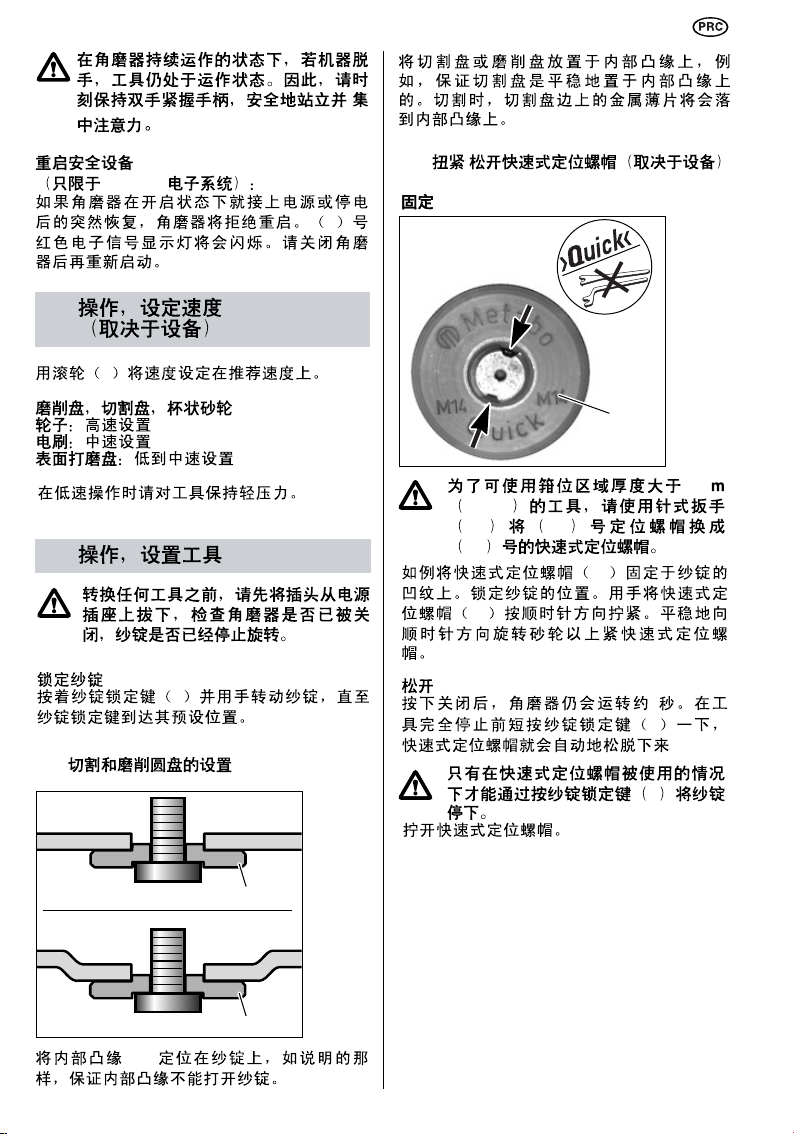
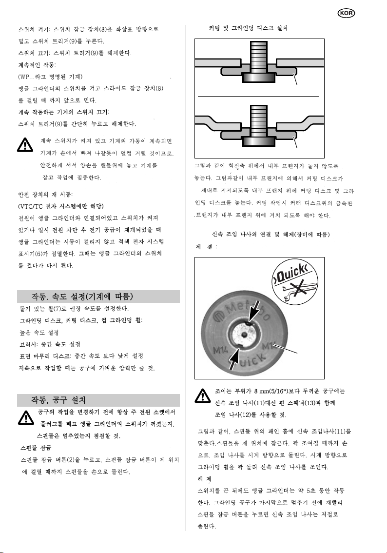
10.1 Fitting cutting and grinding discs
Locate the inner flange (10) on the spindle, as
illustrated, ensuring that the inner flange cannot
turn on the spindle.
Position the cutting disc or the grinding disc on
the inner flange, as illustrated, ensuring that the
cutting disc is supported evenly by the inner
flange. When cutting, the sheet metal flange on
the cutter disc should be resting on the inner
flange.
10.2 Securing/releasing the Quick clamping nut (depending on equipment)
Securing
10 Operation, Fitting Tools
Before any tool changing operation,
always remove the plug from the mains
supply socket and check that the angle
grinder is switched off and that the
spindle has come to a halt.
Locking the spindle
Press in the spindle-lock button (2) and turn the
spindle by hand until the spindle-lock button can
be felt to engage in position.
For tools which are thicker than 8 mm
(5/16”) in the clamping area, use the
clamping nut (12) with the pin spanner
(13) instead of the Quick clamping nut
(11).
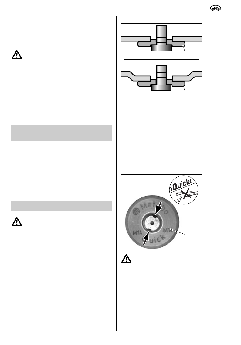
Fit the Quick clamping nut (11) in the grooves on
the spindle as illustrated. Lock the spindle in
position. Turn the Quick clamping nut (11)
clockwise by hand until tight. Tighten the Quick
clamping nut by turning the grinding wheel firmly
in a clockwise direction.
25
Page 26
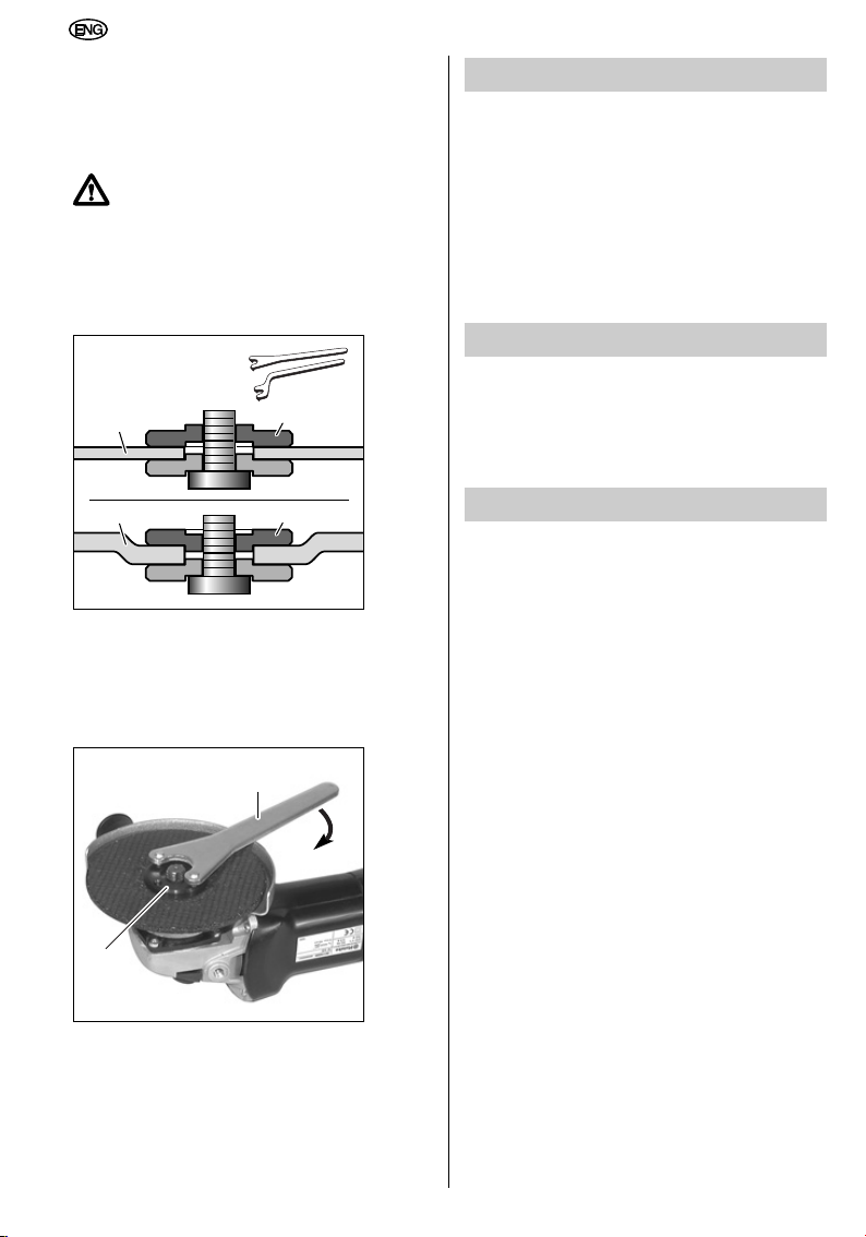
Releasing
12
13
12
12
B
A
After switch-off, the angle grinder runs on for
approx. 5 seconds. Press the spindle-lock button
(2) shortly before the grinding tool comes to a
final halt and the Quick clamping nut releases
itself.
Using the spindle-lock button (2) to
stop the spindle is only permitted if the
Quick clamping nut is in use!
Screw the Quick clamping nut off.
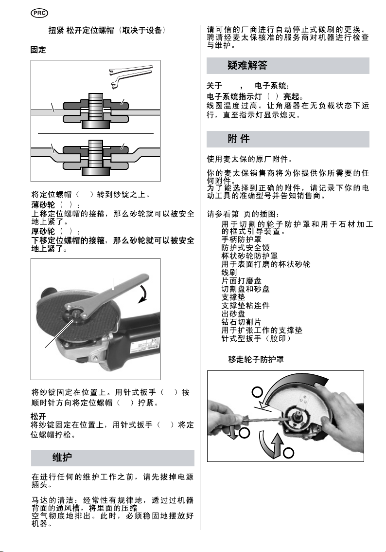
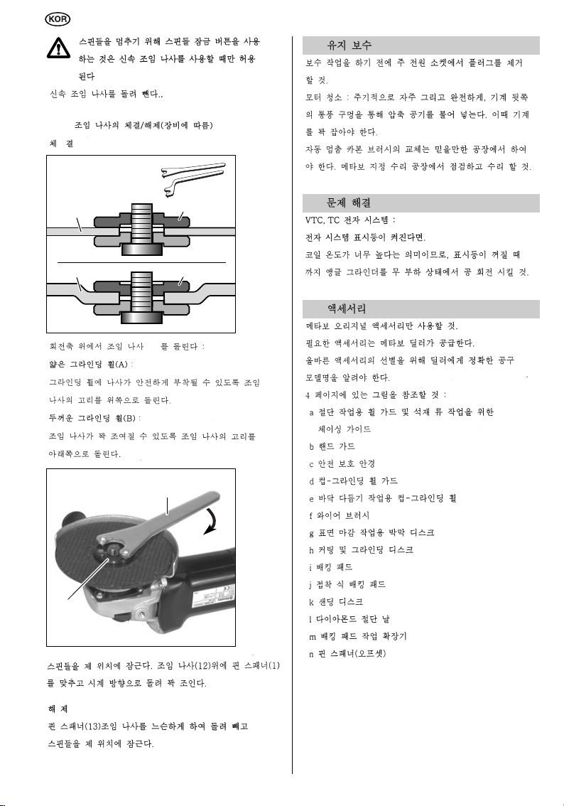
10.3 Securing/releasing the clamping nut
(depending on equipment)
Securing
Turn the clamping nut (12) onto the spindle:
Thin grinding wheels (A):
Move collar of clamping nut upwards, so that the
grinding wheel can be safely clamped securely.
Thick grinding wheels (B):
Move collar of clamping nut downwards, so that
the clamping nut can be fitted securely.
11 Maintenance
Remove the plug from the mains supply socket
before undertaking any maintenance work.
Motor cleaning: blow compressed air through the
rear ventilation slots of the machine regularly,
frequently and thoroughly. Here, the machine
must be held firmly.
The auto-stop carbon brushes must only be
replaced in an accredited workshop. Have checks
and maintenance carried out by Metabo
Authorized Services.
12 Troubleshooting
With VTC, TC electronic system:
electronic system indicator (6) lights up.
The coil temperature is too high. Allow the angle
grinder to run under no-load conditions until the
indicator display is extinguished.
13 Accessories
Use original Metabo accessories only.
Your Metabo dealer will supply you with any
accessories you may require.
To assist in selecting the correct accessories,
make sure that you take a note of the exact
model of your tool for your dealer.
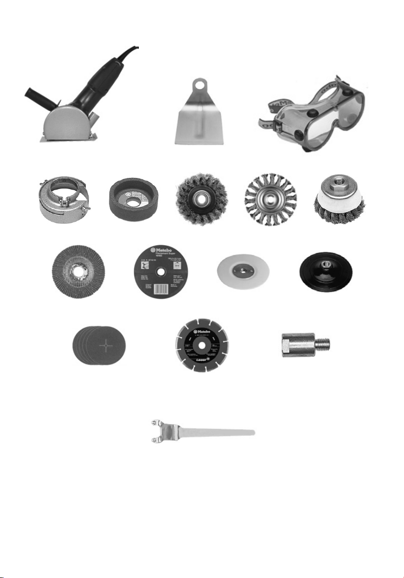
Refer to illustrations on page 4:
a Wheel guard with cutting and chasing guide
for processing stone
b Hand guard
c Safety goggles
d Cup-grinding wheel guard
e Cup-grinding wheel for surface smoothing
f Wire brushes
g Lamellar surface dressing discs
h Cutting and grinding discs
i Backing pads
j Cling-fit backing pads
k Sanding discs
l Diamond cutting blade
m Extension for working with backing pads
n Pin spanner (offset)
Lock the spindle in position. Fit the pin spanner
(13) onto the clamping nut (12) and turn
clockwise to tighten.
Releasing
Lock the spindle in position, slacken off the
clamping nut with the pin spanner (13) and screw
off.
26
Page 27
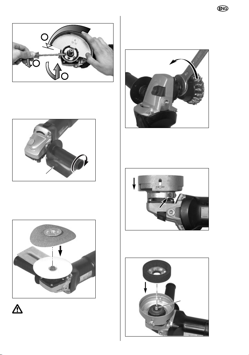
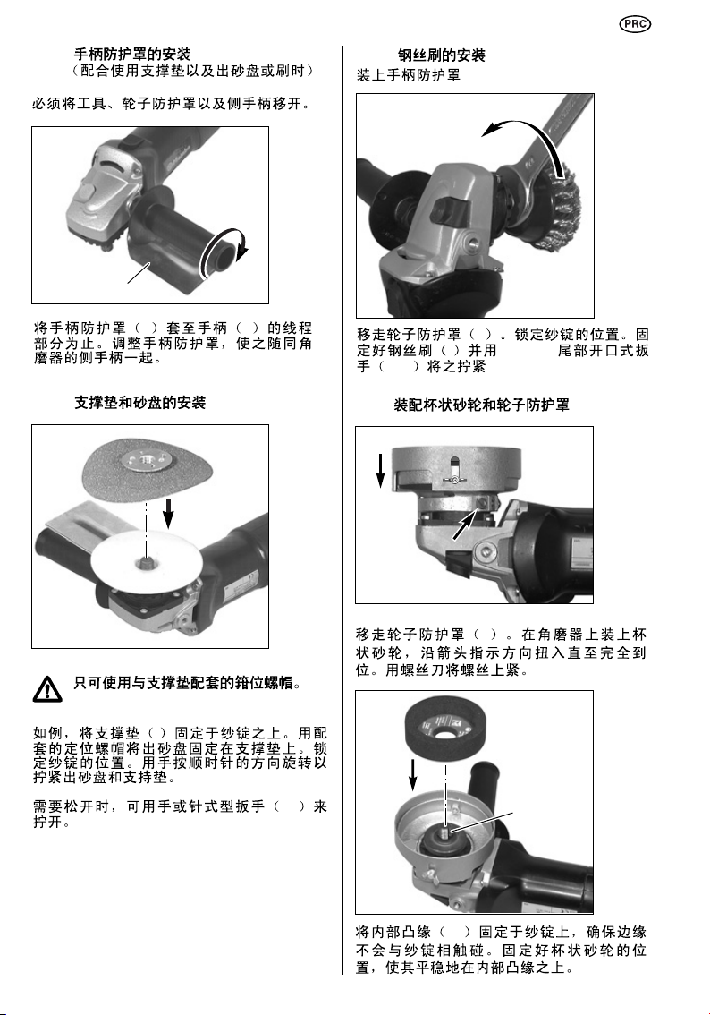
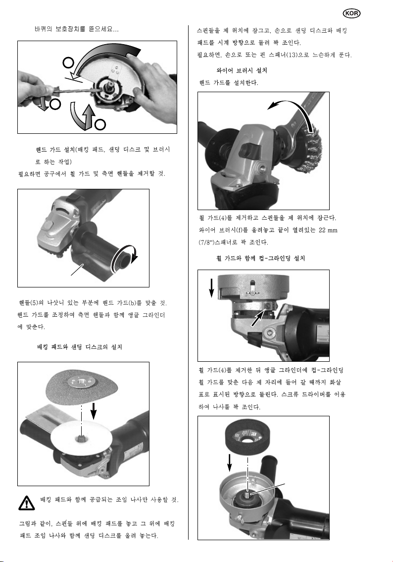
13.1 Removing the wheel guard
10
b
1
2
3
13.2 Fitting the hand guard
(working with backing pad and sanding
disc or brush)
Remove the tool, wheel guard and side-handle,
as necessary.
Fit the hand guard (b) over the threaded part of
the handle (5). Adjust the hand guard and fit to
the angle grinder along with the side-handle.
Slacken off manually or with the pin spanner (13),
as necessary.
13.4 Fitting the wire brush
Fit the hand guard.
Remove the wheel guard (4). Lock the spindle in
position. Mount the wire brush (f) and tighten with
the 22 mm AF open-ended spanner (7/8").
13.5 Fitting the cup-grinding wheel with
wheel guard
13.3 Fitting the backing pad and sanding
disc
Use only the clamping nut supplied
along with the backing pad.
Locate the backing pad (i) on the spindle, as
illustrated. Mount the sanding disc (k) with the
backing pad clamping nut supplied. Lock the
spindle in position. Tighten the sanding disc and
backing pad by turning clockwise by hand.
Remove the wheel guard (4). Fit the cup-grinding
wheel guard to the angle grinder, turning it on in
the direction indicated by the arrow until fully in
position. Use a screwdriver to tighten the screw.
27
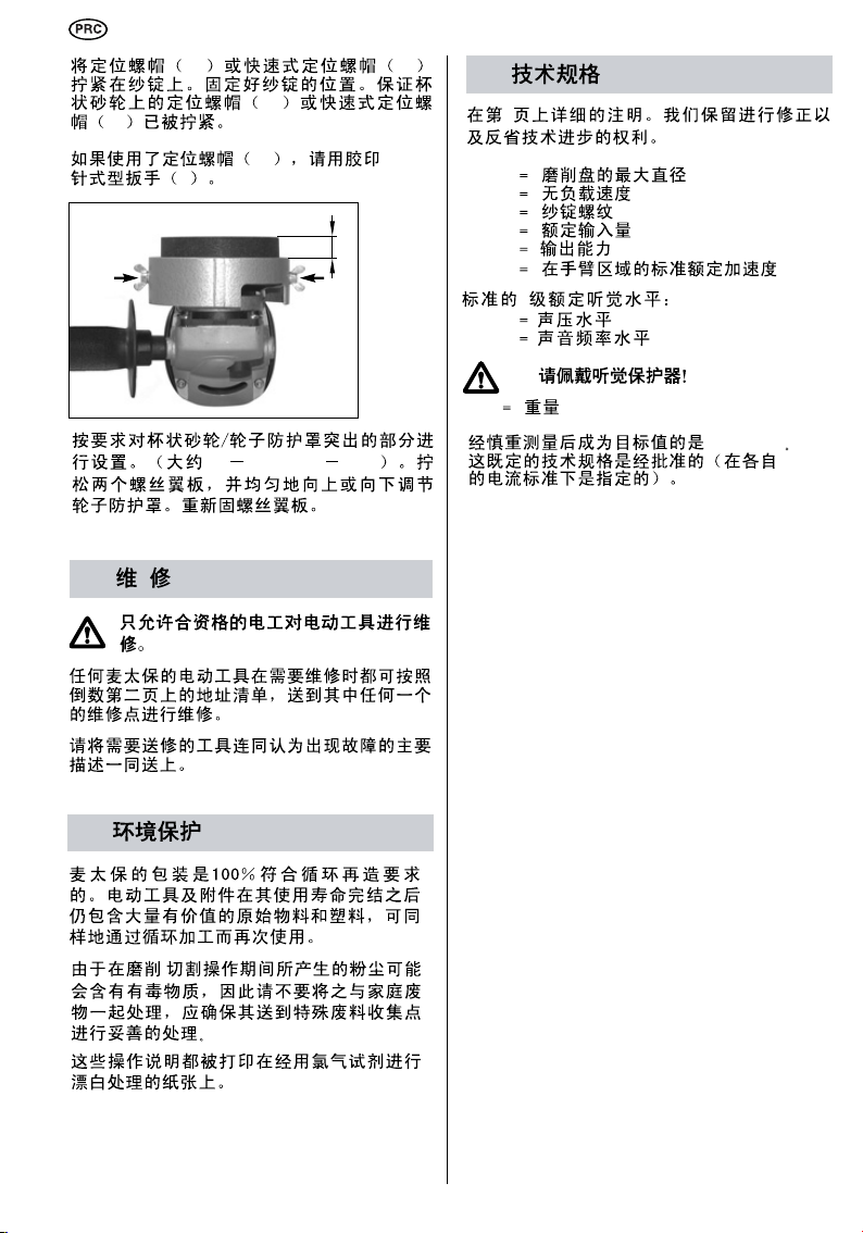
Page 28
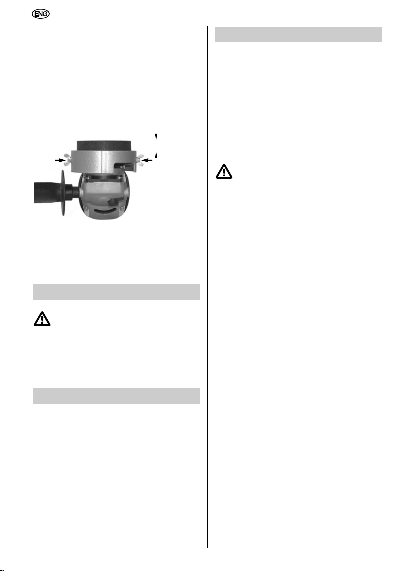
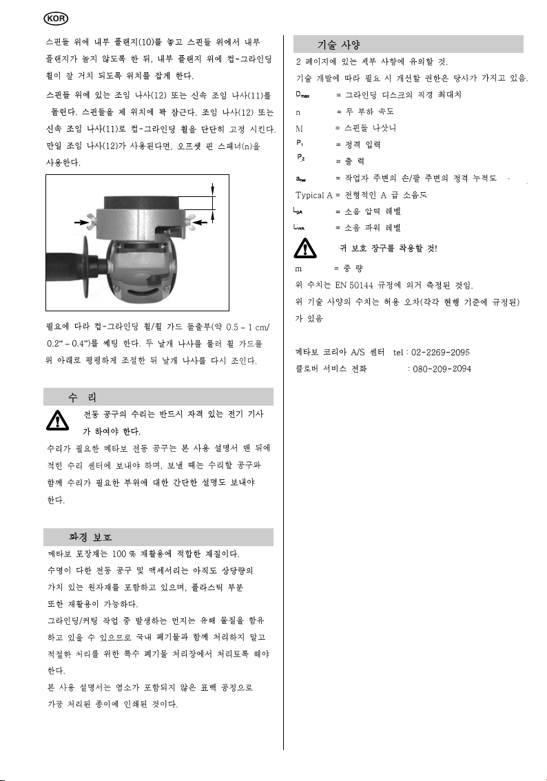
Locate the inner flange (10) on the spindle,
ensuring that the flange cannot turn on the
spindle. Position the cup-grinding wheel so that it
rests evenly on the inner flange.
Screw the clamping nut (12) or the Quick
clamping nut (11) onto the spindle. Lock the
spindle in position. Secure the cup-grinding wheel
with the clamping nut (12) or the Quick clamping
nut (11).
Use the offset pin spanner (n) if the clamping nut
(12) is being used.
Set the cup-grinding wheel/wheel guard
projection as required (approx. 0.5 - 1 cm/
0.2" - 0.4"). Slacken off the two wing screws and
adjust the wheel guard evenly upwards or down.
Retighten wing screws.
14 Repairs
Repairs to power tools must be carried
out by a qualified electrician only.
Any Metabo power tools in need of repair can be
sent to one of the addresses listed in the spare
parts list.
Please send the tool for repair with a brief
description of the fault identified.
16 Technical Specifications
Notes on the details on page 2.
We reserve the right to undertake modifications to
reflect technical advances.
= maximum grinding disc diameter
D
max
n = no-load speed
M = spindle thread
= rated input
P
1
= output power
P
2
= typically rated acceleration in the
a
hw
hand-arm area
Typical A-rated acoustic level:
= acoustic pressure level
L
pA
= acoustic power level
L
WA
Wear ear protectors!
m = weight
Measured values established according to
EN 50144.
The stated technical specifications are subject to
tolerances (as specified in the respective current
standards).
15 Environmental Protection
Metabo packaging is 100% suitable for recycling.
Power tools and accessories at the end of their
service life still contain large amounts of valuable
raw materials and plastics which can likewise be
fed back into a recycling process.
As the dust generated during grinding/cutting may
contain harmful materials, do not dispose of it
along with domestic waste but ensure it is taken
to a collection point for special waste for proper
disposal.
These Operating Instructions are printed on paper
produced in a chlorine-free bleaching process.
28
Page 29

Page 30

Page 31

Page 32

 Loading...